Fiber Fusion Splicing
50
Ver. E 100607
-
Upload
nitesh-tahariya -
Category
Documents
-
view
48 -
download
6
description
fiber optics
Transcript of Fiber Fusion Splicing

Ver. E 100607

Prepared & Presented By:FiberNext, LLC
3 Robinson Rd., Suite A3, Bow, NH 03304Ph: 603-226-2400 - www.fibernext.com
“Fiber Optics 301”A training guide for installing
fiber optic cabling systems in accordance withANSI/EIA/TIA & IEEE standards

Fiber Cleaving

Fiber Splicing: CleavingBefore a technician can make a quality fiber optic join with either
mechanical fittings or fusion systems, the fiber must be cleaved tovery tight tolerances. Cleaving is always the first (and most
important) step toward successful splicing.
InnoVF-77

Fusion Splicing: Cleave ToolsThe purpose of fiber cleaving is to cut the glass strand with a
“close to perfect” 90 degree cut for specific processes. Cleaverselection begins with basic, hand held tools that offer cleavequality within 2 to 7 degrees. These are low cost hand toolsdesigned for general purpose cleaving. The can be used for
mechanical splicing and pre-polished connectors.
AFLCT02
FitelS310
T&B92208

Fusion Splicing: Cleave ToolsCleaver selection continues with precision “bench-top” tools that offer
cleave quality of 0.0 to 1.0 degrees. These are more expensive toolsdesigned for critical quality fiber cleaving. Can be used for mechanical
splicing, pre-polished connectors and fusion splicing.
FitelS323
SumitomoFC6SC
AFLCT30

Fusion Splicing: Cleaving Process
Precision cleavers utilize a highquality carbide wheel that is calibratedto engage the fiber by less than 1-2 um
Retention Pads1

Retention Pads2
This process creates a “score” line thatwill be opened to create a quality cleave.
Fusion Splicing: Cleaving Process

Fusion Splicing: Cleaving Process
Retention Pads
Anvil
At this point the user depresses an anvil that “activates”the score point and opens the cleave face. Pressure is
controlled by the retention pads to help keep theshear line of the cleave as close to 90 as possible.

Fusion Splicing: Cleaving Process
As the anvil is depressed, the scored point in the fiberopens under the pressure and moves upward toward the
anvil. During this process, on certain models, the retentionpads release as a final step (after the cleave is complete).
Retention Pads
Anvil

Fusion Splicing: Cleaving Inspection
Examples of Shattered Fibers
Examples of Poorly Cleaved Fibers
Examples of Properly Cleaved Fibers

MechanicalSplicing

Mechanical Splicing
A mechanical splice is a semi-permanent connection between twofibers made with an alignment device and index matching fluid or
adhesive. Back reflection and loss can vary dramatically therefore, it’smost common use is for restoration of multi-mode fiber.

Mechanical Splicing: Splice Process
Utilizing a hand held cleaver, the fiber must be cleaved to length asdetermined by the type of splice being used. Note the graduated
scale. In the example shown, the “hammer” will be depressed ontothe fiber to create a score on the glass.

Mechanical Splicing: Splice Process
Gently bend the tongue of the cleaver to open the cleave face.Do not clean the bare fiber after completing this step due to possible
contamination.

Mechanical Splicing: Splice Process
Pictured in this example is the typical packaging of a mechanicalsplice. This product is hermetically sealed to eliminate the possibility
of contamination to the index matching gel.
Mechanical Splicing: Splice Process
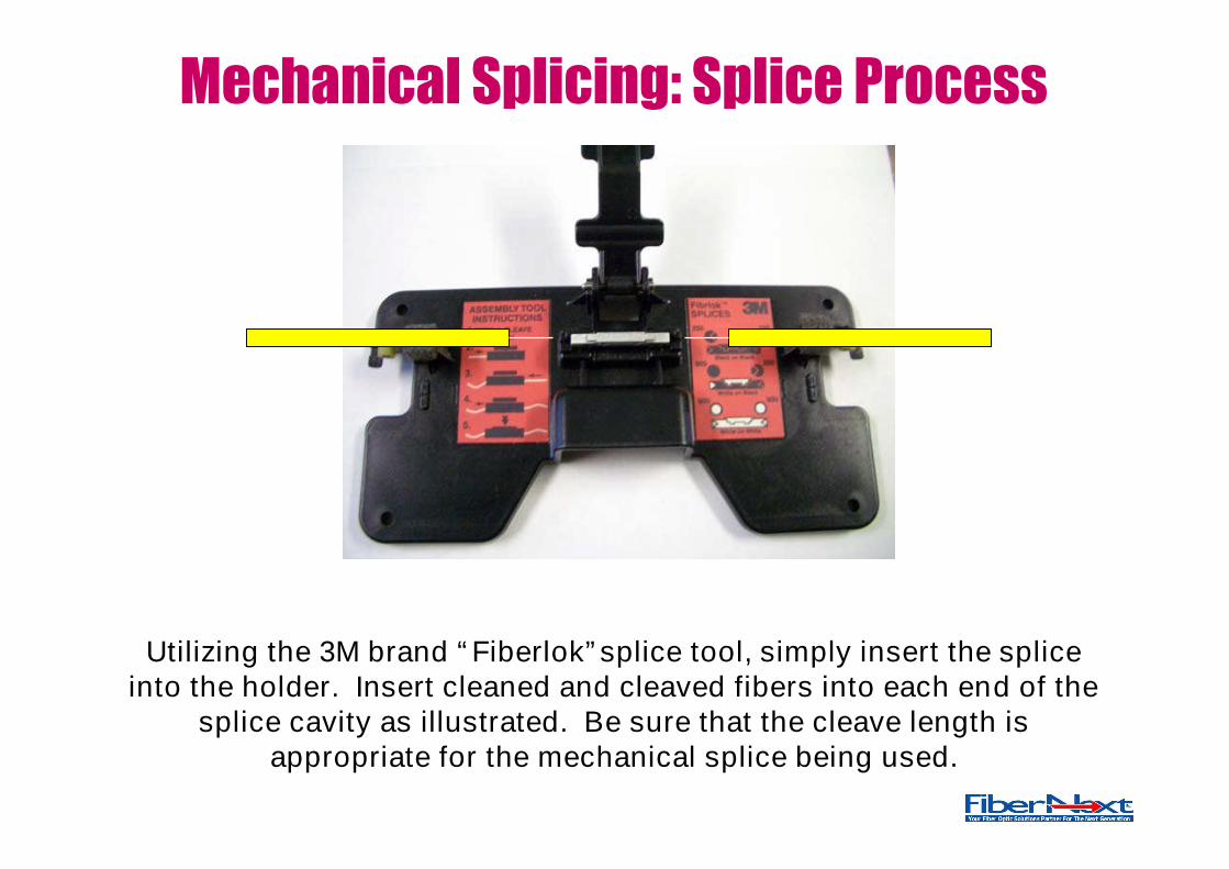
Utilizing the 3M brand “Fiberlok”splice tool, simply insert the spliceinto the holder. Insert cleaned and cleaved fibers into each end of the
splice cavity as illustrated. Be sure that the cleave length isappropriate for the mechanical splice being used.

Mechanical Splicing: Splice Process
Once the fiber ends have been fully seated into the splice, lower theactivation head and fully depress the splice mechanism.

Mechanical Splicing: Splice Process
Shown here is a close up a fully depressed andactivated mechanical splice.

Section 4:Fusion Splicing

Fusion Splicing: Splice Process
Fusion splicing optical fibers creates an extremely low loss connection,with little to no back reflection. Essentially, this equipment “welds”
optical fiber strands together utilizing an electrical arc current. Thereare a variety of devices available including V-groove machines with SM
losses averaging .05dB and Core-Align machines with SM lossesaveraging .02dB.

Fusion Splicing: V-GrooveEntry level fusion splicing equipment is in a category called V-
groove technology. These machines can produce splice losses thatare typically .05dB for singlemode and .02 (or less) for multimode.
Price range is between $7K and $10K.
AFLFSM17S
CorningX75
DiamondZeus

Fusion Splicing: Portable FTTXThese highly portable machines, designed for the FTTX market, come in
both V-Groove and Core Align models and can produce splice losses thatare typically between .05dB for singlemode and .02dB (or less) for
multimode. Price range is between $9K and $12K.
FitelS177A
AFLFSM11S
SumitomoTomcat

Fusion Splicing: Modern Core AlignToday’s modern splicing equipment is capable of splicing fibers inunder 9 seconds, including cleave estimate, alignment, splice, loss
evaluation and proof test. These splicers are capable of .01dBsinglemode splices in each arc. Prices range from $19K to $24K.
Data is downloadable to a PC for archiving.
FitelS176 AFL
FSM50S
SumitomoType 39

Single FiberSplicing

Fusion Splicing: Device Generalities
Splice Bed Cover /Wind Protector
Fiber View Screen
Battery Pack or ACCharger Module

Fusion Splicing: Device Generalities
Protection Sleeve Heater
Device Controls forPerforming the FusionProcess and Setting UpMenu Operations
X/Y Axis Views /Fiber Profile

Fusion Splicing: Mechanics of a Splicer
Fiber Alignment Guides
Fiber Illumination LED
Motor operated sleds

Fusion Splicing: Mechanics of a Splicer
Magnetic Latches
Primary Fiber Retention Cleat
Retention Pad
Secondary Cleat /Alignment Guide

Fusion Splicing: Mechanics of a Splicer
CCD Cameras for fiber viewing

Fusion Splicing: Mechanics of a Splicer
Electrodes

Fusion Splicing: Mechanics of a Splicer
Fiber is manually inserted into the “splice bed” area. This area is locatedbetween the center (apex) of the electrodes and the outside edge of the
V-groove. Use caution not to contact the endface of the fiber to the V-grooveThen, flip down the retention cleats. Be sure to install heat shrink first!
A B

Fusion Splicing: Mechanics of a Splicer
A B
Flip down the primary retention cleat firstThen, flip down the alignment guide

Fusion Splicing: Mechanics of a Splicer
A B
Then, flip down the environmental coverand initiate a splice.

Fusion SplicingTechnology

Fusion Splicing: V-groove Fundamentals
CCDLens

Example of PAS Alignment
LED (a)
LED(b)
CCD (a)
CCD(b)
The index of refraction mismatchbetween the cladding and the
core material causes a profile orshadow of the core diameter tobe cast against a CCD camera.

Fusion Splicing: Core-align Fundamentals
CCDLens

Fusion Splicing: Core-align Fundamentals

Fusion Splicing: Core-align Fundamentals

Fusion Splicing: Splice Process

Fusion Splicing: Splice Quality
Bubbled Splice, Endface Debris
Lossy Splice (Shaded), Incorrect ARC Power
Core Mismatch, Poor Alignment

Fusion Splicing: Splice Quality
Normal Splices, Correct ARC Power

After splicing is complete, remove the spliced fibers fromThe splice bed
And guide the splice protection sleeve up to the splice point.
Cure the heat shrink tube in the oven for the proper time.Notice adhesive sealing the fusion tube.
Fusion Splicing: Splice Process

Efficient fiber splicing is a direct byproduct of proper area setupwhich includes sufficient space, lighting, and well planned fiber
management practices.
Splicing Process Summary
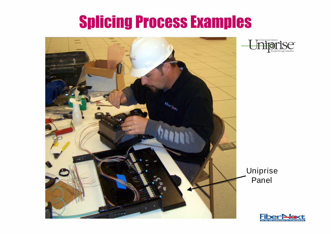
Splicing Process Examples
UniprisePanel

Splicing Process Examples
PLP StainlessEnclosure
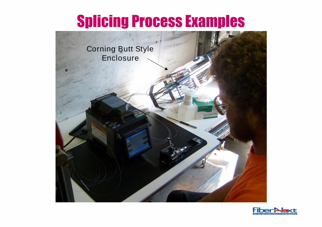
Splicing Process Examples
Corning Butt StyleEnclosure

Splicing Process Examples
Century Fiber OpticsFTS350 S/TM Panels
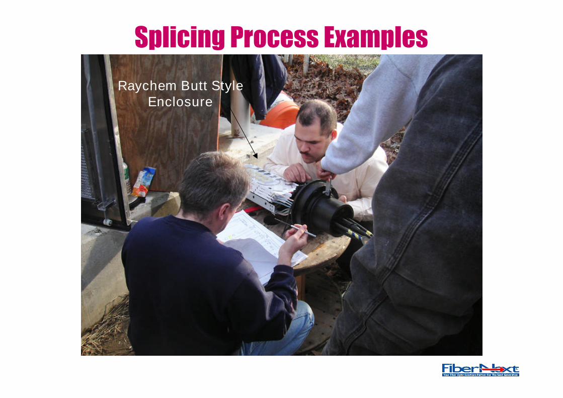
Splicing Process Examples
Raychem Butt StyleEnclosure