F:GCS Product ManualsBasyx PSC ControllerBASYX PSC...
27
Basyx PSC Programmable System Controller Installation Manual PSC-IM Revision 4.1 03/08/11 Global Control Solutions GCS
Transcript of F:GCS Product ManualsBasyx PSC ControllerBASYX PSC...

Basyx PSCProgrammable System Controller
Installation ManualPSC-IM Revision 4.1
03/08/11
Global Control SolutionsGCS

Page 2
Basyx PSCProgrammable System Controller
Table of Contents
Before Installing 3PSC Board Layout 4Mounting the Controller 5Connecting the Power 6Communications Bus Wiring 7Setting the Device Address 9Connecting the Universal Inputs 10
Setting The Input DIP Switches 10Connecting a Temperature Sensor (Thermistor) 12Connecting a Voltage Sensor 12Connecting a Current Sensor 14Connecting a Digital Device 15
Connecting the Meter Inputs 16Connecting the Digital Outputs 17
Operating the Hand-Off-Auto (HOA) Switches 18Connecting Analog Outputs 19
Installing the Basyx AOB Board 19Connecting Analog Device 20
Installing the Basyx M24 Modem 21Operation 22Basic Troubleshooting 22Specifications 23About the Basyx Product Line 24
Appendix 1: Basyx Address Switch Settings 25Appendix 2: Recommended Cable 27
Warning ( For your Safety )
All electrical connections must be in agreement with local codes, ordinances or the National Electric Code (NEC).
Do not install in areas that experience high levels of electrical interference, moisture or exposure to water.

Page 3
BEFORE INSTALLING
Check contents for any sign of damage. If the PSC is damaged in any way, contact the dealer or seller immediately.
The Basyx PSC comes complete with a Snap-Track mounting channel, and may be installed in a NEMA typeenclosure, equipment control section or other NEC approved enclosure.
Figure 1: Basyx PSC universal controller
The PSC controller is designed for use on new construction projects or retrofit of existing HVAC equipment or lightingsystems. The PSC is ideal for control of air handlers, chillers, boilers and lighting control and is a stand-alone unitwhich contains all logic and algorithms for complete control of selected equipment.
Contact Global Control Solutions or your local dealer/distributor if unsure about the compatibility of any existingequipment or application.
NOTE: For descriptive purposes, all references to location of components on the board describedherein are based on the board positioned as shown in Figure 1 and Figure 2.

Page 4
PSC BOARD LAYOUT
Figure 2: PSC Board Layout
The PSC controller contains eight (8) universal inputs, eight (8) digital outputs with SPDT relays and HOA switches,four (4) digital/meter inputs. With the optional plug-on Basyx AOB analog output board, four (4) 0-10vdc or 4-20maoutputs may be added.
An optional plug-on modem allows access from remote locations.
The board provides 5vdc and 32vdc auxiliary power for 0-10vdc or 4-20ma temperature, humidity and pressuresensors. DIP switches control the pull-up resistor circuit for low impedence voltage sensors, and provide a 499 ohmresistor for current sensors, eliminating the need to physically install parallel resistors across the inputs.
PSC CONTROLLER
+ -1
+ -2
+ -4
+ -3
+ -5
+ -6
+ -7
+ -8
+ - + -REF
24VAC
L2
NO
1NCC NO
2C NC NO
3NCC NO
4C NC
NO5
NCC NO6C NC NO
7NCC NO
8C NC
RS485 COMM
REF+ -1
+ -2
+ -3
+ -4
METER INPUTS
MODEM
UNIVERSAL INPUTS
DIGITAL OUTPUTS H - O - A
IN OUT
ADDRESS
RESET
10VDC
499 OHM
OFFON
OUTIN
G IN OUTG G G +5 +32
AUX POWER RS232 DIRECT
RI CD OH
CPU
L1PWR
UNIVERSAL INPUTS DIGITAL OUTPUTS 1-4
DIGITAL OUTPUTS 5-8DIGITAL INPUTS RS485 COMM AUX POWER RS232 DIRECT POWER
TELEPHONE LINE
MODEM / AO BOARD SOCKET
AI SWITCHES

Page 5
MOUNTING THE CONTROLLER
The PSC must be mounted in a relatively clean environment, free from major airborne dust and contaminants(moisture, oil, etc). Keep the PSC away from high voltage equipment that might disrupt communications and awayfrom high vibration equipment. Do not mount the unit near any sources of electromagnetic interference (EMI) orflammable vapors.
Mount the PSC by attaching the Snap-Track mounting channel into the desired location. Attach the Snap-Track byinserting proper type screws through the slots in the base of the channel. Make sure that the screw is tightenedsufficiently to hold the track, but do not over-tighten to the point of bowing the track. Insure that the board will nottouch the head of the mounting screw.
The Basyx PSC may be mounted in any orientation, and mounting should be such that there is easy access to thewiring terminals.
Figure 3: PSC and Snap-Track Mounting Channel
Figure 3 shows the mounting channel and PSC controller. After mounting the channel, carefully snap the PSC boardinto place by inserting 1 side into the groove of the Snap-Track, and gently pressing on the opposite side of the boarduntil it snaps into place.
PSC CONTROLLER
+ -1
+ -2
+ -4
+ -3
+ -5
+ -6
+ -7
+ -8
+ - + -REF
24VAC
L2
NO
1NCC NO
2C NC NO
3NCC NO
4C NC
NO5
NCC NO6C NC NO
7NCC NO
8C NC
RS485 COMM
REF+ -1
+ -2
+ -3
+ -4
METER INPUTS
MODEM
UNIVERSAL INPUTS
DIGITAL OUTPUTS H - O - A
IN OUT
ADDRESS
RESET
10VDC
499 OHM
OFFON
OUTIN
G IN OUTG G G +5 +32
AUX POWER RS232 DIRECT
RI CD OH
CPU
L1PWR
SNAP-TRACK MOUNTING CHANNEL
USE CAUTION WHEN INSERTING THE PSC CONTROLLER INTO THE SNAP-TRACK. DO
NOT FLEX THE BOARD MORE THAN NECESSARY TO PUSH INTO PLACE.
USE PAN-HEAD SCREWS TO ATTACH SNAP-TRACK TO DESIRED ENCLOSURE.
MOUNTING SLOTS

Page 6
CONNECTING THE POWER
The PSC must be powered by a 24VAC Class 2 low voltage transformer. To connect the power wiring to the PSCboard, locate the terminals along the bottom edge of the board marked “24VAC” and connect to the power source. Figure 4 illustrates the PSC showing the location of the 24VAC terminal Block.
NOTE: For 24 VAC power, use only power supplies with a Class 2 transformer rating.
Do not power with any voltage other than the 24VAC low voltage listed. Connect power to the PSC by connectingwires from the transformer to the 24VAC terminals L1 and L2. The terminals are labeled on the board above theterminal strip. The red indicator LED left of the terminal strip will illuminate when the power is properly connected andturned on.
For connections to the PSC, strip the wire back approximately 3/16" and insert into the terminal block. Back out thescrew on the terminal block until the bare wire inserts fully, and turn the screw back down until there is firm tension onthe wire. Make sure that the clamp secures the stripped portion of the wire, and that no insulation is under the clamp.
Figure 4: Basyx PSC Power Connections
PSC CONTROLLER
24VAC
L2 NO5
NCC NO6C NC NO
7NCC NO
8C NC
DIGITAL OUTPUTS H - O - A
L1PWR
24VAC
+ -
120VAC CIRCUIT
MULTIPLE CONTROLLERS MAY BE POWERED FROM A SINGLE TRANSFORMER, USE 10VA
PER PSC FOR TRANSFORMER SIZING.24VAC CLASS 2TRANSFORMER

Page 7
NOTE: Multiple PSC controllers may be powered from a single transformer. Use 7VA for transformersizing when designing power configurations.
COMMUNICATIONS BUS WIRING
The Basyx PSC can be used in a stand alone configuration or in an array utilizing hundreds of units. If used in a largearray, the BASYX IPM repeater must be used if controller count exceeds 32 total controllers. In addition, multiple non-addressed channels or loops may be used for physical separation of channels (See Figure 5) in order to eliminate acontinuous loop in a large or multi-story building. The BASYX system will support a total controller count of 256 PSCor VAV controllers.
All communication wiring consists of a 1 pair, shielded cable (See Figures 5 & 6). Use 18 AWG, twisted pair stranded, shielded, plenum rated cable (Recommended Belden 6300FE) for all communications wiring. Whenconnecting a channel of controllers from an IPR repeater, connect communications in a daisy chain configuration.
Communication is via EIA RS-485 protocol. This requires that the system be wired according to the followingmethods and rules:
• Communications cable must be 1 twisted pair (Belden 6300FE), 18 AWG, plenum rated.• The total distance of any channel or loop must not exceed 4000 feet. • The drain wire of the communication cable must NOT be connected to the
PSC or VAV controller. Twist drain wires from the incoming and outgoing cables together to create singleshield for the entire daisy chain, and connect to ground at one end only (suggest the IPR or first controllerlocation).
• Connection of the REF terminal on the PSC controller is NOT required.• Each controller in the system must have a unique address, regardless of configuration of channel. Refer to
the instructions in the next section for setting the Device Address (ADDR) dip switch.
Connect the communications wiring to the terminal blocks on the edge of the PSC controller marked +, -, and REF as shown in Figure 6.
CAUTION: All communication wiring must be connected such that the plus (+) terminal is wired to a plus terminal and the minus terminal (-) is wired to a minus terminal. Do not install communications cables nearpower cables or in power conduits. Isolate all communications wiringfrom large motors, fluorescent lighting fixtures or other sources ofhigh intensity electromagnetic interference (EMI).
Page 8
Figure 5: Basyx Typical Communications Loop Configuration
As shown, communications loops may contain any mixture of Basyx controllers. Each controller must have a uniqueaddress setting for proper operation.
A single loop containing a minimum of one (1) PSC and up to 31 additional PSC or VAV controllers may be used.
IPR 1
RFC 2
RFC 3
RFC 5
RFC 6
RFC 8
PSC 9
RFC 10
VAV 12
VAV 13
VAV 15
BASYX IPM REPEATERS
BASYX CONTROLLERS
ADDITIONAL CHANNEL 1
CONTROLLERS
ADDITIONAL IPM REPEATERS
MAIN RS485 COMMUNICATIONS BUS
CHANNEL RS485 COMMUNICATIONS BUS
RFC 4 PSC 7 RFC 11 VAV 14
ADDITIONAL CHANNEL 2
CONTROLLERS
ADDITIONAL CHANNEL 3
CONTROLLERS
ADDITIONAL CHANNEL 4
CONTROLLERS
TOTAL SYSTEM CONTROLLER CAPACITY OF 256
MINIMUM OF ONE (1) PSC CONTROLLER MUST BE USED
AHEAD OF IPR REPEATERS FOR CHANNEL CONFIGURATION
PSC 1
IPR 2 IPR 3 IPR 4

Page 9
Figure 6: Typical PSC Communications Connection Details
SETTING THE DEVICE ADDRESS
If the PSC is used as a stand alone controller make sure that the address is set to #1.
If more than one PSC is used on the same communications bus then each device must have a different address forproper communication. The address switch is located towards the left end of the board about ½ way up. Refer toAppendix 1 for setting the device address to a number between 1 and 256. The communication address for eachdevice must be unique.
NOTE: Do not skip addresses in a daisy chain; begin at 1 and count up. The boards do nothave to be in consecutive order, however all addresses must be included.
To set the address, refer to appendix 1 and push any of the five (5) switches required UP (towards universal inputs) toset to ON.
+ - + -REF
RS485 COMM
REF+ -1
+ -2
+ -3
+ -4
METER INPUTSIN OUT
G
CONNECT SHIELD WIRE TO EARTH GROUND
RED
BLAC
K
+ - + -REF
RS485 COMM
REF+ -1
+ -2
+ -3
+ -4
METER INPUTSIN OUT
G
RED
TWIST SHIELD WIRES TOGETHER - DO NOT CONNECT TO BOARD
BLAC
K
RED
BLAC
K
PSC 1 PSC 2
ADDITIONAL PSC or VAV CONTROLLERSTOTAL SYSTEM CAPACITY OF 256
RS485 COMMUNICATIONS BUS
THE REF TERMINAL ON THE RS485 COMMUNICATIONS IS NOT REQUIRED - NO CONNECTION SHOULD BE MADE TO THESE
TERMINALS1 PAIR, 18-22GA SHIELDED CABLE

Page 10
CONNECTING THE UNIVERSAL INPUTS
The Basyx PSC provides eight (8) universal inputs which may be used for thermistors, resistance, 0-10VDC, 4-20MA or digital contact closures. Typical applications include temperature, humidity, pressure and other analog ordigital devices.
All input cables should be 18 AWG, and must consist of stranded, twisted pairs (as required), shielded type with lessthan 20 pF capacitance per foot.
NOTE: Connect all sensor cable drain wires to earth ground.
CAUTION: Do not run sensor wires near power cables or in power conduits. Isolate all sensorwires from large contactors or motors, fluorescent light fixtures and other sources ofhigh intensity electromagnetic interference (EMI).
SETTING THE INPUT DIP SWITCHES
The PSC contains two eight (8) position DIP switches immediately to the left of the universal input terminal strip.
The switches are numbered 1-8 left to right, and correspond to the input used i.e. switch 1 = input 1,switch 2 = input 2 etc. Figure 7 illustrates the location of the universal input DIP switches.
Figure 7: Universal Input DIP Switches
+ -1
+ -2
+ -4
+ -3
+ -5
+ -6
+ -7
+ -8
UNIVERSAL INPUTS
10VDC
499 OHM
OFFON
OUTIN
PSC CONTROLLER
10VDC SWITCH IS CLOSEST TO THE EDGE OF THE BOARD
499 OHM RESISTOR SWITCH IS THE INNER SET OF SWITCHES

Page 11
The 0-10VDC set of switches (closest to the edge of the board) sets the status of the 0-10vdc excitation voltage forthe input. The switch is factory set to ON, and will normally remain ON for most input devices. If using a self-generating 0-10vdc device which does not require excitation voltage, slide the switch up (OFF) to disengage thereference voltage. Figure 8 illustrates the operation of the 0-10VDC universal input DIP switches.
Figure 8: Universal Input 0-10VDC Dip Switch Operation
The 499 OHM set of switches (below the 0-10VDC) inserts a 499 ohm resistor across a corresponding input, and isused with a 4-20ma sensor only. This switch eliminates the need to physically install a resistor across the inputterminals. Figure 9 shows the settings for the 499 OHM switches.
Figure 9: Universal Input 499 OHM Dip Switch Operation
OFF
ON10VDC
TO DISABLE THE 10VDC EXCITATION VOLTAGE, PUSH THE SWITCH UP (OFF). THIS APPLIES TO SELF-GENERATING VOLTAGE INPUT DEVICES ONLY.
OUT
IN499 OHM
TO INSERT THE 499 OHM RESISTOR INTO THE CIRCUIT, PUSH THE DIP SWITCH DOWN (IN). THIS
APPLIES TO 4-20mA INPUTS ONLY.

Page 12
CONNECTING A TEMPERATURE SENSOR (THERMISTOR)
Temperature sensors are typically type II thermistors, and are available from a variety of suppliers. Make sure thattype II sensors are used to insure proper temperature monitoring and control.
Thermistors are not polarity sensitive, and cannot be connected backwards. It is recommended that any color codingpertaining to the + and - connections on the board be consistent within the system. The 0-10VDC DIP switch asoutlined above must be set to ON, and the 499 OHM switch must be be set to OUT.
Figure 10 indicates a typical thermistor connection, and shows a duct temperature sensor installation.
Figure 10: Typical Thermistor (Temperature) Connection
CONNECTING A VOLTAGE SENSOR
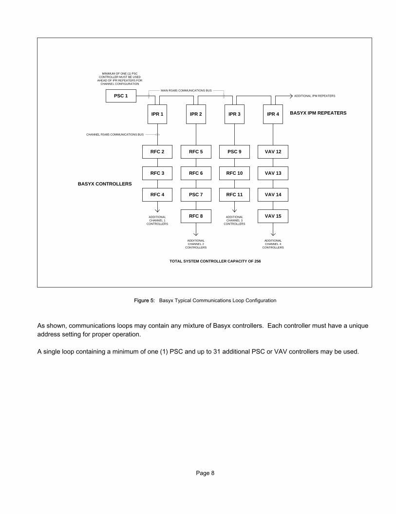
The PSC can accept any 0-10VDC sensor input, and typical applications include humidity, pressure or other analogtype sensors. The sensor is powered by an external 24VDC power supply, or may be powered from the 32VDCauxiliary voltage source on the PSC controller. The 0-10VDC DIP switch as outlined above will set to ON, and the499 OHM switch will be set to OUT.
Figure 11 illustrates a voltage sensor powered by an external source, and shows a typical duct pressure differentialsensor. Figure 12 shows the same sensor powered by the PSC auxiliary power.
NOTE: Voltage sensors normally require 3 wires for proper connection. The specificmanufacturers labeling may vary from that shown on the typical drawings. It is imperative that the power and signal wires be connected properly, or serious damage to the PSC board may occur. Refer to your device installation instructions for exact wiring and termination labeling.
BLACKRED
1 PAIR CABLE
PSC CONTROLLER
GREEN
WHITE
BUTT SPLICES - DO NOT USE WIRE NUTS
INSTALL SENSOR UPSTREAM IN ENTERING AIR DUCT
AC
I/10K-C
P-D4
DUCT SENSOR
RED
BLACK
AU
TOM
ATION
CO
MPO
NE
NTS
, INC
.
+ -1
+ -2
+ -4
+ -3
+ -5
+ -6
+ -7
+ -8
UNIVERSAL INPUTS
10VDC
499 OHM
OFFON
OUTIN
RE
DBLA
CK
Page 13
Figure 11: Voltage Input Wiring Using External Power Source
Figure 12: Voltage Input Wiring Using PSC Auxiliary Power Source
PSC CONTROLLER
+ -1
+ -2
+ -4
+ -3
+ -5
+ -6
+ -7
+ -8
UNIVERSAL INPUTS
10VDC
499 OHM
OFFON
OUTIN
- +
VDC OUT
WH
ITER
ED
24VDC POWER SUPPLY
BLAC
K
BLACKRED
WHITE
OU
T
+ - RE
MO
TEZE
RO
SETPO
INT
RE
LAY
1
2.5
5
10
JP6
JP3
5V 10V
BI / UNIPXD-100
SLIDE SWITCH
RANGE
DUCT STATIC PRESSURE SENSOR
VERIS INDUSTRIES
THIS EXAMPLE SHOWS TYPICAL WIRING CONNECTIONS:
RED = 24VDC+WHITE = 24VDC-BLACK = SIGNAL TO PSC (0-10VDC)
IMPORTANT !!
MAKE SURE THAT THE POWER AND SIGNAL WIRES ARE CONNECTED CORRECTLY. MIS-WIRING MAY CAUSE SERIOUS DAMAGE TO THE PSC CONTROLLER.
WH
ITE
WH
ITE
BLACKRED
WHITE
OU
T
+ - RE
MO
TEZER
O
SETPOIN
T R
ELAY
1
2.5
5
10
JP6
JP3
5V 10V
BI / UNIPXD-100
SLIDE SWITCH
RANGE
DUCT STATIC PRESSURE SENSOR
VERIS INDUSTRIES
THIS EXAMPLE SHOWS TYPICAL WIRING CONNECTIONS:
RED = 24VDC+WHITE = 24VDC-BLACK = SIGNAL TO PSC (0-10VDC)
IMPORTANT !!
MAKE SURE THAT THE POWER AND SIGNAL WIRES ARE CONNECTED CORRECTLY. MIS-WIRING MAY CAUSE SERIOUS DAMAGE TO THE PSC CONTROLLER.
PSC CONTROLLER
+ -1
+ -2
+ -4
+ -3
+ -5
+ -6
+ -7
+ -8
+ - + -REF
RS485 COMM
REF+ -1
+ -2
+ -3
+ -4
METER INPUTS
MODEM
UNIVERSAL INPUTS
IN OUT
ADDRESS
RESET
10VDC
499 OHM
OFFON
OUTIN
G IN OUTG G G +5 +32
AUX POWER RS232 DIRECT
RI CD OH
CPU
PWR
RED
WH
ITE
BLAC
K
REDWHITE
BLACK

Page 14
CONNECTING A CURRENT SENSOR
The PSC can accept any 4-20mA sensor input, and typical applications include humidity, pressure or other analogtype sensors. The sensor is powered by an external 24VDC power supply, or may be powered from the 32VDCauxiliary voltage source on the PSC controller. The 0-10VDC DIP switch as outlined above must be set to ON, andthe 499 OHM switch must be be set to IN.
Figure 13 illustrates a current sensor powered by an external source, and shows a typical humidity sensor. Figure 14shows the same sensor powered by the PSC auxiliary power.
NOTE: Current sensors typically require 2 wires for proper connection. The specific manufacturers labeling may vary from that shown on the typical drawings. It is important that the power and signal wires be connected properly, or serious damage to the PSC controller may occur. Refer to your sensor installation instructions for exact wiring and termination labeling.
Figure 13: Current Input Wiring Using External Power Source
PSC CONTROLLER
+ -1
+ -2
+ -4
+ -3
+ -5
+ -6
+ -7
+ -8
UNIVERSAL INPUTS
10VDC
499 OHM
OFFON
OUTIN
- +
VDC OUT
WH
ITER
ED
24VDC POWER SUPPLY
BLAC
K
BLACKRED
Io
Vin
ACI/RH-2-R
ROOM HUMIDITY SENSOR
AUTOMATION COMPONENTS.
THIS EXAMPLE SHOWS TYPICAL WIRING CONNECTIONS:
RED = 24VDC+WHITE = JUMPER FROM POWER SUPPLY TO TMS150BLACK = SIGNAL TO PSC (4-20mA)
IMPORTANT !!
MAKE SURE THAT THE POWER AND SIGNAL WIRES ARE CONNECTED CORRECTLY. MIS-WIRING MAY CAUSE SERIOUS DAMAGE TO THE PSC CONTROLLER.
WH
ITE

Page 15
Figure 14: Current Input Wiring Using PSC Auxiliary Power Source
IMPORTANT: When using the PSC auxiliary power source for voltage or currentinputs, verify that the sensor used in your application will operate at the 32VDC power level. Serious damage may occur to the device if not rated at this voltage.
CONNECTING A DIGITAL DEVICE
Digital inputs connected to the universal inputs are 2 position status points only, and will not accumulate closures orpulse counts. If using an electric or flow type pulse meter, use the METER input connections as described in the nextsection.
Digital inputs are used for binary indication (on/off) of a toggle switch, pressure differential switch, current switch, flowswitch or other 2 position contact closure. Make sure that the contact is a dry closure, and that no external voltage isapplied through this circuit. Digital inputs are not polarity sensitive, and can not be connected backwards. It isrecommended that any color coding pertaining to the + and - connections on the board are consistent within thesystem. The 0-10VDC DIP switch as outlined above must be set to ON, and the 499 OHM switch must be set toOUT.
IMPORTANT !!
MAKE SURE THAT THE POWER AND SIGNAL WIRES ARE CONNECTED CORRECTLY. MIS-WIRING MAY CAUSE SERIOUS DAMAGE TO THE PSC CONTROLLER.
PSC CONTROLLER
+ -1
+ -2
+ -4
+ -3
+ -5
+ -6
+ -7
+ -8
+ - + -REF
RS485 COMM
REF+ -1
+ -2
+ -3
+ -4
METER INPUTS
MODEM
UNIVERSAL INPUTS
IN OUT
ADDRESS
RESET
10VDC
499 OHM
OFFON
OUTIN
G IN OUTG G G +5 +32
AUX POWER RS232 DIRECT
RI CD OH
CPU
PWR
RED
BLAC
K
REDBLACK BLACK
REDIo
Vin
ACI/RH-2-R
ROOM HUMIDITY SENSOR
THIS EXAMPLE SHOWS TYPICAL WIRING CONNECTIONS:
RED = 24VDC+BLACK = SIGNAL TO TMS150 (4-20mA)
AUTOMATION COMPONENTS.

Page 16
CONNECTING THE METER INPUTS
The Basyx PSC provides four (4) meter inputs which may be used for electric, flow or other pulse generating digitaldevices used for consumption monitoring. These inputs are also ideal for connection of override switches ormomentary contact pushbuttons.
All input cables should be 18 AWG, and must consist of stranded, twisted pairs (as required), shielded type with lessthan 20 pF capacitance per foot.
NOTE: Connect all the input cable drain wires to earth ground.
CAUTION: Do not run meter input wires near power cables or in power conduits. Isolate all inputwires from large contactors or motors, fluorescent light fixtures and other sources ofhigh intensity electromagnetic interference (EMI).
Make sure that the contact is a dry closure, and that no external voltage is applied through this circuit. Digital inputsare not polarity sensitive, and cannot be connected backwards. It is recommended that any color coding pertaining tothe + and - connections on the board be consistent within the system. The 0-10VDC DIP switch as outlined abovemust be set to ON, and the 499 OHM switch must be set to OUT. Figure 15 illustrates the meter input wiring, and shows a typical flow transmitter for monitoring liquid flow.
Figure 15: Typical Meter Input Wiring Detail
-+
VDC OUT
WH
ITER
ED
24VDC POWER SUPPLY
PULSE OUT +
UFT-1
FLOW TRANSMITTER
KELE & ASSOCIATES
PULSE OUT -
mA SIGNAL OUT
XDCR SIGNAL IN
24VDC POWER
COMMON
BLUE
BLACK
RED
WHITE
+ - + -REF
RS485 COMM
REF+ -1
+ -2
+ -3
+ -4
METER INPUTSIN OUT
G
PSC CONTROLLER
BLU
EB
LAC
K
THIS EXAMPLE SHOWS THE UFT-1 FLOW TRANSMITTER AND THE REQUIRED PULSE AND POWER CONNECTIONS. FOR OTHER PULSE METERS, WIRE AS SHOWN FROM THE UFT-1 PULSE
OUTPUTS TO THE PSC METER INPUTS

Page 17
CONNECTING THE DIGITAL OUTPUTS
The Basyx PSC contains eight (8) digital outputs for binary (on/off) control of HVAC, lighting or other systemequipment. Each output is a form C SPDT contact closure through an on-board pilot duty relay. Each output iscontrolled through a hand-off-auto toggle switch for local override of any system output point.
CAUTION: Relay outputs on the PSC board are designed for pilot duty only. Do not attemptto switch line voltage through these contacts, as serious damage to the board orconnected system may occur. Switch low voltage 24VAC/VDC circuits only.
All input cables should be 18 AWG, and must consist of stranded, twisted pairs (as required), shielded type with lessthan 20 pF capacitance per foot.
NOTE: Connect all input cable drain wires to earth ground. Do not run meter input wiresnear power cables or in power conduits. Isolate all input wires from large contactors or motors, fluorescent light fixtures and other sources of high intensity electromagnetic interference (EMI).
Figure 16 shows connection of a field relay powered from an exterior transformer.
Figure 16: Typical Output Wiring with Relay Control
NO
1NCC NO
2C NC NO
3NCC NO
4C NC
DIGITAL OUTPUTS H - O - A
24VAC
+ -
120VAC CIRCUIT
24VAC CLASS 2TRANSFORMER
RE
D
BLAC
K
RED
RED
PSC CONTROLLER
BLAC
K
RED
24VACRELAY
LOAD CONTROL CIRCUIT

Page 18
Figure 17 shows typical rooftop unit connections.
Figure 17: Typical Rooftop Unit Output Wiring
Note that the jumper wire connecting all of the output commons initiates at the Fan output. This is highlyrecommended and insures that compressors and heat will not operate if the fan is disabled, either by the PSC or themanual HOA switch.
OPERATING THE HAND-OFF-AUTO (HOA) SWITCHES
The Basyx PSC contains eight (8) hand-off-auto switches for local override of the individual outputs. The position ofthese switches is a follows:
Manual ON Push the switch lever completely to the LEFT. This will energize the relayand turn the output ON.
Manual OFF Position the switch lever in the CENTER. This will de-energize the relayand turn the output OFF.
Automatic Push the switch lever completely to the RIGHT. This places the outputs inthe automatic mode, which is under control of the computer programming.
+ -7
+ -8
24VAC
L2
NO
1NCC NO
2C NC NO
3NCC NO
4C NC
NO5
NCC NO6C NC NO
7NCC NO
8C NC
DIGITAL OUTPUTS H - O - A
L1PWR
WH
ITE
BLA
CK
BLU
E
GR
EEN
RED
BR
OW
N
R
G
W1
W2
Y1
Y2
RED
GREEN
WHITE
BLACK
BLUE
BROWN
ROOFTOP UNIT
PSC
NOTE THAT THE JUMPER WIRE FOR HEAT/COOL STAGES IS
CONNECTED TO THE FAN OUTPUT
LOW
VOLTAG
E TER
MIN
AL STR
IP

Page 19
CONNECTING ANALOG OUTPUTS
The optional Basyx AOB plug-in board provides four (4) analog outputs for control of modulating devices such asdampers, valves, variable speed drives and other items using a modulating input signal.
The AOB board has individual jumpers for selection of 0-10VDC or 4-20MA output signals.
The examples shown indicate typical wiring. Consult your specific device manufacturer’s instructions for exact wiringand interface requirements. Contact GCS if unsure about the compatibility of any selected device.
INSTALLING THE BASYX AOB BOARD
The Basyx AOB board must be installed with the power turned off to the PSC controller and communications wiringdisconnected. Failure to do so will void the product warranty, and may result in serious damage to the controller andAOB board.
The AOB board inserts into the socket along the left edge of the PSC board marked “MODEM”, and is a pass-thrudevice which will also allow the insertion of the Basyx M24 modem option (see next section). The device will extendout from the end of the board, so take this into consideration when mounting the PSC into a panel or other enclosure.
Figure 18 shows the installation of the Basyx AOB board.
Figure 18: Basyx AOB Analog Output Board Installation
To install the board, carefully line up the pins on the bottom of the Basyx AOB with the sockets on the PSC controller. When accurately lined up, gently press on the AOB board and the unit will snap into place. After installation, verifythat no pins have bent, or are not securely seated in the sockets.
+ -1
+ -2
+ -4
+ -3
+ -5
+ -6
+ -7
+ -8
+ - + -REF
RS485 COMM
REF+ -1
+ -2
+ -3
+ -4
METER INPUTS
MODEM
UNIVERSAL INPUTS
IN OUT
ADDRESS
RESET
10VDC
499 OHM
OFFON
OUTIN
G IN OUTG G G +5 +32
AUX POWER RS232 DIRECT
RI CD OH
CPU
+-
+-
+-
+-
BASYX AOB
2
3
4
10-10
4-20MA
0-10
4-20MA
0-10
4-20MA
0-10
4-20MA
PSC CONTROLLER
THE PINS ON THE BOTTOM OF THE BASYX AOB ARE VERY DELICATE - USE CAUTION WHEN
SEATING AND INSTALLING THE BOARD

Page 20
CAUTION: The pins on the bottom of the Basyx AOB board are very delicate. Use cautionwhen installing this module and make sure that all pins are accurately lined up withthe socket before applying pressure.
CONNECTING ANALOG DEVICE
Figure 19 illustrates connection of a standard damper or valve actuator to the PSC controller. This application showsa 0-10VDC input actuator and requires that the actuator be powered from the SAME transformer which is poweringthe PSC controller. When connecting the actuator, make sure to maintain the L1 (HOT) and L2 (COMMON)connections within the system.
DANGER: The PSC analog output is designed for use with an actuator using full-wave power. Serious damage will occur to the VAV board if connected to a half-wave device. If unsureabout your selected actuator, call Global Control Solutions technical support.
Figure 19: Typical Actuator Wiring with Common Transformer
+-
+-
+-
+-
BASYX AOB
2
3
4
10-10
4-20MA
0-10
4-20MA
0-10
4-20MA
0-10
4-20MA
PSC CONTROLLER
+ -1
+ -2
+ -4
+ -3
+ -5
+ -6
+ -7
+ -8
+ - + -REF
24VAC
L2
RS485 COMM
REF+ -1
+ -2
+ -3
+ -4
METER INPUTS
UNIVERSAL INPUTS
IN OUT
ADDRESS
RESET
10VDC
499 OHM
OFFON
OUTIN
G IN OUTG G G +5 +32
AUX POWER RS232 DIRECT
RI CD OH
CPU
L1PWR
24VAC
+ -24VAC
TRANSFORMER
120VAC CIRCUIT
RED
ACTUATOR0-10VDC INPUT
REDWHITE
BLACK
24VAC
COM
0-10 INPUT
WHITE
BLACK

Page 21
INSTALLING THE BASYX M24 MODEM
The Basyx M24 modem must be installed with the power turned off to the PSC controller. Failure to do so will voidthe product warranty, and may result in serious damage to the controller and modem.
The M24 modem inserts into the socket along the left edge of the PSC board marked “MODEM”, or will plug into thetop of the Basyx AOB analog output board if installed (see previous section).
IMPORTANT: The Basyx M24 modem must be installed on the PSC board address 1 for proper operation. Global communications features originate in board 1, and communications errors may be incurred if not connected to board 1.
Figure 20 shows the installation of the Basyx M24 modem.
Figure 20: Modem Installation
The green portion of the PC board is towards the address switch when properly installed. Make sure that all pins areseated accurately in the socket, and gently press on the modem until it snaps in place. After installation, verify that nopins have bent or are not securely in the sockets.
+ -1
+
+ -1
+ -2
METER INPUTS
MODEM
ADDRESS
RESET
10VDC
499 OHM
OFFON
OUTIN
RI CD OH
CPU
BASYX M24
PSC CONTROLLER
THE EXPOSED PCB PORTION OF THE MODEM GOES TO THE RIGHT TOWARDS
THE ADDRESS SWITCH AS SHOWN
MODEM MAY BE INSTALLED ON BASYX AOB ANALOG BOARD IF PRESENT
XE2
486A
D
XEC
OM
DW
EM
M01
BXE
2400
G

Page 22
OPERATION
The red indicator light next to the 24VAC terminal block illuminates solid when the power is on. When the unit isoperating properly, the CPU light next to the address switch will blink intermittently to indicate proper CPU operation.
BASIC TROUBLESHOOTING
If the PSC does not operate properly, perform the necessary troubleshooting as described below.
SYMPTOM ACTION
Failure to communicate: Check that the power is on and that the red indicator light is on. If it is on, measure voltage at the 24VAC power terminals of the PSC to ensure that the unit is getting 24VAC ( -10% / +5%). Check the continuity and connection of the communication wires.Check that the device address is correctly set.
Faulty Communication: Check that all communication cables are connected as required, with drain wires connected to a solid earth ground.Check that all communication cable wires are connected “+” terminal to”+” terminal and “-” terminal to “-” terminal.Check for continuity on all communication signal lines.Isolate sensor wiring from large contactors, fluorescent light fixtures, and other sources of high-intensity electromagnetic interference (EMI).
Digital outputs not responding: Disconnect the device wiring and check for continuity at the between common ( C ) and normally open ( NO ) terminals based on output position.Check to see that exterior voltage source is present if used to switch pilot relays.
Analog or digital inputs are jumpy: Isolate sensor wiring from large contactors, motors, fluorescent light fixtures, and other sources of high-intensity electromagnetic interference (EMI).

Page 23
SPECIFICATIONS
Communication: EIA RS-485 at 9600 baud on 18AWG shielded, plenum rated cable(recommended Belden 6300FE or equivalent)
Power Requirements: 24VAC (-10% / 5%), 50/60/HzCurrent: 3.2VARecommend 5VA transformer sizing for AC power
Universal Inputs: (8) Universal inputs Thermistor 10,000 ohm type II material0-10vdc >/= 100 ohm input impedance0-20ma </= 500 ohm input impedance
Resistance 0-10,000 ohmsDry contact >/= 50ms timing
Digital Inputs: (4) Meter inputs Dry contact >/= 50ms timing
Digital Outputs: (8) Dry contacts SPDT pilot duty rated at 1 amp at 24VAC or 24VDC
Analog Outputs (Optional): (4) 0-10VDC or 4-20MA with >/= 1K ohm drive impedence
Ports: RS-485 communications busRS-232 direct connect busRS-232 modem socket
Environmental Limits: Temperature: 32oF to 125oF.Humidity (non-condensing): 95%
Enclosure: 4" Snap-track mounting channel
UL Listing: ANSI/UL 916
Dimensions: 8.5"W x 4.0"H x 1.5"D
Shipping Weight: Approx. 1.1 lbs.

Page 24
ABOUT THE BASYX PRODUCT LINE
The PSC is one product in a line of Basyx control products. The TriComm interface software package is a Windowsbased human interface used with the Basyx automation and control system. Tricomm will operate on any personalcomputer with the Windows 98,ME,NT,2000, XP or VISTA operating system.
The program provides a simple interface through direct connect, modem or internet to setup, operate and modify theoperating parameters of the Basyx system, using easy to understand point-and-click commands. The drop-downsystem menus allow access to all system functions, and requires minimal computer experience for normal dailyinteraction with the system.
The Basyx system is designed specifically to meet today’s building automation, facility and energy managementneeds. Global Control Solutions develops and provides application support for control systems around then world. The company has a continuing commitment to research and development in order to provide new and improvedproducts to the building automation market.
For more information contact:
Global Control Solutions6307-C Angus DriveRaleigh, NC 27617
Telephone: (919) 785-2855Fax: (919) 785-2385
E-mail: [email protected]: www.globalcontrolsolutions.net
The technical contents of this document, while accurate as of publication, are subject to change without notice.No responsibility is assumed for its use.
Page 25
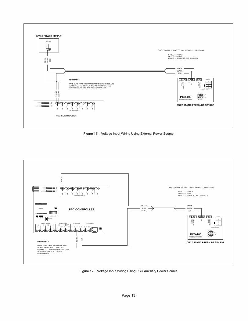
APPENDIX 1 - BASYX ADDRESS SWITCH SETTINGS
ADDRESSES 1-32
ADDRESS SW 1 SW 2 SW 3 SW 4 SW 5 SW 6 SW 7 SW 8
1 ON OFF OFF OFF OFF OFF OFF OFF
2 OFF ON OFF OFF OFF OFF OFF OFF
3 ON ON OFF OFF OFF OFF OFF OFF
4 OFF OFF ON OFF OFF OFF OFF OFF
5 ON OFF ON OFF OFF OFF OFF OFF
6 OFF ON ON OFF OFF OFF OFF OFF
7 ON ON ON OFF OFF OFF OFF OFF
8 OFF OFF OFF ON OFF OFF OFF OFF
9 ON OFF OFF ON OFF OFF OFF OFF
10 OFF ON OFF ON OFF OFF OFF OFF
11 ON ON OFF ON OFF OFF OFF OFF
12 OFF OFF ON ON OFF OFF OFF OFF
13 ON OFF ON ON OFF OFF OFF OFF
14 OFF ON ON ON OFF OFF OFF OFF
15 ON ON ON ON OFF OFF OFF OFF
16 OFF OFF OFF OFF ON OFF OFF OFF
17 ON OFF OFF OFF ON OFF OFF OFF
18 OFF ON OFF OFF ON OFF OFF OFF
19 ON ON OFF OFF ON OFF OFF OFF
20 OFF OFF ON OFF ON OFF OFF OFF
21 ON OFF ON OFF ON OFF OFF OFF
22 OFF ON ON OFF ON OFF OFF OFF
23 ON ON ON OFF ON OFF OFF OFF
24 OFF OFF OFF ON ON OFF OFF OFF
25 ON OFF OFF ON ON OFF OFF OFF
26 OFF ON OFF ON ON OFF OFF OFF
27 ON ON OFF ON ON OFF OFF OFF
28 OFF OFF ON ON ON OFF OFF OFF
29 ON OFF ON ON ON OFF OFF OFF
30 OFF ON ON ON ON OFF OFF OFF
31 ON ON ON ON ON OFF OFF OFF
32 OFF OFF OFF OFF OFF ON OFF OFF

Page 26
ADDRESSES 33-64:
ADDRESS SW 1 SW 2 SW 3 SW 4 SW 5 SW 6 SW 7 SW 8
33 ON OFF OFF OFF OFF ON OFF OFF
34 OFF ON OFF OFF OFF ON OFF OFF
35 ON ON OFF OFF OFF ON OFF OFF
36 OFF OFF ON OFF OFF ON OFF OFF
37 ON OFF ON OFF OFF ON OFF OFF
38 OFF ON ON OFF OFF ON OFF OFF
39 ON ON ON OFF OFF ON OFF OFF
40 OFF OFF OFF ON OFF ON OFF OFF
41 ON OFF OFF ON OFF ON OFF OFF
42 OFF ON OFF ON OFF ON OFF OFF
43 ON ON OFF ON OFF ON OFF OFF
44 OFF OFF ON ON OFF ON OFF OFF
45 ON OFF ON ON OFF ON OFF OFF
46 OFF ON ON ON OFF ON OFF OFF
47 ON ON ON ON OFF ON OFF OFF
48 OFF OFF OFF OFF ON ON OFF OFF
49 ON OFF OFF OFF ON ON OFF OFF
50 OFF ON OFF OFF ON ON OFF OFF
51 ON ON OFF OFF ON ON OFF OFF
52 OFF OFF ON OFF ON ON OFF OFF
53 ON OFF ON OFF ON ON OFF OFF
54 OFF ON ON OFF ON ON OFF OFF
55 ON ON ON OFF ON ON OFF OFF
56 OFF OFF OFF ON ON ON OFF OFF
57 ON OFF OFF ON ON ON OFF OFF
58 OFF ON OFF ON ON ON OFF OFF
59 ON ON OFF ON ON ON OFF OFF
60 OFF OFF ON ON ON ON OFF OFF
61 ON OFF ON ON ON ON OFF OFF
62 OFF ON ON ON ON ON OFF OFF
63 ON ON ON ON ON ON OFF OFF
64 OFF OFF OFF OFF OFF OFF ON OFF

Page 27
APPENDIX 2 - RECOMMENDED CABLE
This document lists the recommended cable types and part numbers for the various connections to the Basyx buildingautomation and control system hardware. GCS recommends the New Generation product line from Belden Wire &Cable, and suggests that any substitutions meet or exceed the technical specifications of those cables listed.
Communications Cable
Belden 6300FE 1 twisted, shielded pair Communications18 AWG, Plenum rated
Belden 6541FE 2 twisted pairs w/overall shield Communications22 AWG, Plenum rated
Sensor & Output Cable
Belden 6300FE 1 twisted pair w/overall shield Sensors & Outputs18 AWG, Plenum rated
Belden 6342FE 3 twisted pairs w/overall shield Sensors & Outputs18 AWG, Plenum rated
Belden 6343FE 4 twisted pairs w/overall shield Sensors & Outputs18 AWG, Plenum rated
Belden 6345FE 6 twisted pairs w/overall shield Sensors & Outputs18 AWG, Plenum rated
Belden 6347FE 9 twisted pairs w/overall shield Sensors & Outputs18 AWG, Plenum rated
Specialty Cable
Belden 6541FE 2 twisted pairs w/overall shield Room Sensor RJ11 Jack22 AWG, Plenum rated
Belden 6542FE 3 twisted pairs w/overall shield Room Sensor 22 AWG, Plenum rated R / RS / RO / RSO
Multi-paired cable should be used for ALL connections to the Basyx system, multi-conductor cable should be avoideddue to capacitance issues. ALL cables should be shielded type, and drain wires should be connected to solid earthground.