Fewa Regulation 2013
219
Electricity Wiring Regulations (Third Edition) Public Consultation 03 December 2013 CD/R01/102
-
Upload
anonymous-gdzqty88zr -
Category
Documents
-
view
768 -
download
115
description
wiring regulation by fewa
Transcript of Fewa Regulation 2013

Electricity Wiring Regulations (Third Edition) Public Consultation
03 December 2013 CD/R01/102

Document Approved by Recipients of controlled copies
CD/R01/ MP Bureau Library, Electricity Distribution Licensees
Electricity Wiring Regulations (Third Edition) – Public Consultation
Author Document Version Publication date Approved by
MY/CKL CD/R01/102 01 03 December 2013 MP Page 1 of 18
The Electricity Wiring Regulations – Third Edition
Public Consultation
CD/R01/102
03 December 2013

Electricity Wiring Regulations (Third Edition) – Public Consultation
Author Document Version Publication date Approved by
MY/CKL CD/R01/102 01 03 December 2013 MP Page 2 of 18
Contents
Contents .................................................................................................. 2
1. Introduction .................................................................................... 3
Purpose of this consultation ....................................................................... 3
Purpose of the Regulations ........................................................................ 3
Next steps .................................................................................................. 3
How to respond .......................................................................................... 4
Help with queries ........................................................................................ 4
Confidentiality ............................................................................................. 4
Consultation Annex A .............................................................................. 5
Consultation Annex B – Proposed changes ............................................ 6
Consultation Annex C ........................................................................... 18
Electricity Wiring Regulations (Third Edition) – Public Consultation
Author Document Version Publication date Approved by
MY/CKL CD/R01/102 01 03 December 2013 MP Page 3 of 18
1. Introduction
Purpose of this consultation
1.1 This consultation process is aimed at gathering the views of stakeholders on the proposed changes to The Electricity Wiring Regulations 2007 (Revision 1, January 2009).
1.2 The Bureau would like to receive the views of anyone who is involved in the design, construction, installation, testing, maintenance or operation of electrical installations in any premises. We encourage any interested party to use this opportunity to communicate their views.
Purpose of the Regulations
1.3 The purpose of these Regulations is to establish standards and principles that promote
the design, construction, installation, maintenance and operation of safe and efficient LV Electrical Installations in all Premises within the Emirate of Abu Dhabi.
1.4 The Regulations promote the installation and operation of safe electricity wiring systems in premises and are broadly based on the general principles defined in British Standard BS 7671 (otherwise known as the IEE Wiring Regulations, UK), which are also similar to the International Standard IEC 60364. The Regulations also take account of the physical environment in Abu Dhabi and the skills and language diversity of the region.
1.5 These Regulations were first published in 2007, referred to as the “Electricity Wiring Regulations 2007” and were effective from 1 January 2008. The Bureau subsequently issued Revision 1 of the Regulations, which were effective from 1 January 2009. Effective from 1 August 2013 the Bureau’s publications will be called ‘Editions’ instead of ‘Revisions’. Henceforth, upon completion of this consultation, the Bureau plans to issue the “Electricity Wiring Regulations (Third Edition)”, to be effective in early January 2014.
Next steps
1.6 The Bureau is seeking comments on the proposed changes to The Electricity Wiring
Regulations 2007 (Rev 1 January 2009).
1.7 A copy of the proposed changes to the main body of the Regulations including the Appendices and Guidance Notes is provided in Annex A and a table summarising the proposed changes is provided in Annex B.
1.8 A copy of the Bureau’s consultation response template is provided in Annex C and responses should be submitted in this format if possible.
1.9 The consultation will run until 31 December 2013.
1.10 The Bureau will publish its response to the comments received at http://www.rsb.gov.ae.
Electricity Wiring Regulations (Third Edition) – Public Consultation
Author Document Version Publication date Approved by
MY/CKL CD/R01/102 01 03 December 2013 MP Page 4 of 18
How to respond
1.10 When responding, please state whether you are responding as an individual or representing the views of an organisation. If responding on behalf of an organisation, please make it clear who the organisation represents and, where applicable, how the views of members were assembled.
1.11 Responses to this consultation must be received by 31 December 2013.
1.12 You are invited to send comments by:
a) email to: [email protected]; or
b) letter to: Mark Preece, Director of Electricity Networks and HSE, Regulations and Supervision Bureau, P.O. Box 32800, Abu Dhabi.
1.13 Printed copies of this consultation document may be obtained by post on written request from:
Mark Preece, Director of Electricity Networks and HSE, Regulations and Supervision Bureau, P.O. Box 32800, Abu Dhabi.
1.14 Electronic version of this consultation may be viewed and downloaded from the RSB website at http://www.rsb.gov.ae.
Help with queries
1.15 Questions about policy issues raised in the document can be addressed to:
Chee K Lee, Distribution Networks Manager, Regulations and Supervision Bureau, P.O. Box 32800, Abu Dhabi or [email protected].
1.16 Any questions should be sent before 24 December 2013.
1.17 If you have comments or complaints about the way this consultation has been conducted they should be sent by 31 December 2013 to:
Gail Lewin, Director of Legal & External Affairs, Regulation and Supervision Bureau, P.O. Box 32800, Abu Dhabi or [email protected].
Confidentiality
1.18 Information received in response to this consultation, including personal information, may be subject to publication or disclosure by the Bureau.
1.19 If you wish any part of your response to remain confidential you must clearly mark those areas of your submission that you wish to remain confidential and provide an explanation in support. The Bureau will consider each request for confidentiality on a case by case basis and will notify you in writing of our decision together with the reasons for our decision.
1.20 If forwarding your response by e-mail, any automatic confidentiality disclaimer which may be generated as an attachment to that e-mail shall not be considered as binding on the Bureau, for the purposes of this consultation.
Electricity Wiring Regulations (Third Edition) – Public Consultation
Author Document Version Publication date Approved by
MY/CKL CD/R01/102 01 03 December 2013 MP Page 5 of 18
Consultation Annex A
The Electricity Wiring Regulations (Third Edition)
The Electricity Wiring Regulations (Third Edition) 1
THEELECTRICITYWIRINGREGULATIONS(THIRDEDITION)
Issued by: the Regulation and Supervision Bureau
for the Water, Wastewater and Electricity Sector in the Emirate of Abu Dhabi
www.rsb.gov.ae
Issued:January 2014
The Electricity Wiring Regulations (Third Edition) 2
Regulation and Supervision Bureau for
the Water, Wastewater and Electricity Sector in the Emirate of Abu Dhabi
Tel: +971 2 654 3666 Fax: +971 2 671 3750 P.O. Box: 32800 Abu Dhabi, U.A.E
e-mail: [email protected] www.rsb.gov.ae

The Electricity Wiring Regulations (Third Edition) 3
ForewordThe Regulation and Supervision Bureau (the Bureau) is established in Abu Dhabi law to oversee the economic and technical activities of electricity and water companies that are licensed to operate in the Emirate of Abu Dhabi. In addition to its duties in respect of licensed companies, the Bureau has certain responsibilities towards the general public, including the assurance of safe and efficient electricity supplies to customers and these Regulations have been produced with this primary aim in mind. The Regulations promote the installation and operation of safe electricity wiring systems in premises and are based on the general principles defined in British Standard BS 7671 (otherwise known as the IEE Wiring Regulations, UK), which are also similar to the International Standard IEC 60364. Such principles are common practice in Abu Dhabi and were adopted in previous documents, including the first Wiring Regulations issued by the old Water and Electricity Department (WED) in 1972. The Regulations also take account of the physical environment in Abu Dhabi and the skills and language diversity of the region. These Regulations were first published in 2007 as the Electricity Wiring Regulations 2007 and were effective from 1 January 2008. The Bureau subsequently issued Revision 1 of the Regulations, which were effective from 1 January 2009. Effective from 1 August 2013 the Bureau’s publications will be called ‘Editions’ instead of ‘Revisions’. Accordingly, following feedback from various parties the Bureau issued its Third Edition of the Regulations, effective 1 January 2014. The Regulations can be downloaded from the Bureau’s website, www.rsb.gov.ae. Nicholas Carter Director General 1 January 2014
The Electricity Wiring Regulations (Third Edition) 4
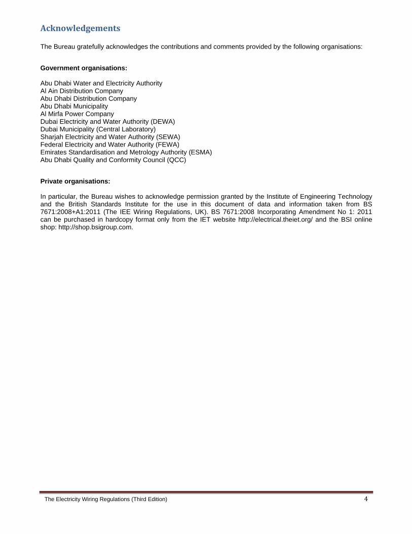
Acknowledgements The Bureau gratefully acknowledges the contributions and comments provided by the following organisations:
Government organisations: Abu Dhabi Water and Electricity Authority Al Ain Distribution Company Abu Dhabi Distribution Company Abu Dhabi Municipality Al Mirfa Power Company Dubai Electricity and Water Authority (DEWA) Dubai Municipality (Central Laboratory) Sharjah Electricity and Water Authority (SEWA) Federal Electricity and Water Authority (FEWA) Emirates Standardisation and Metrology Authority (ESMA) Abu Dhabi Quality and Conformity Council (QCC)
Private organisations: In particular, the Bureau wishes to acknowledge permission granted by the Institute of Engineering Technology and the British Standards Institute for the use in this document of data and information taken from BS 7671:2008+A1:2011 (The IEE Wiring Regulations, UK). BS 7671:2008 Incorporating Amendment No 1: 2011 can be purchased in hardcopy format only from the IET website http://electrical.theiet.org/ and the BSI online shop: http://shop.bsigroup.com.
The
Do The Cha Reg
Clau
Not
Ame
(T
e Electricity W
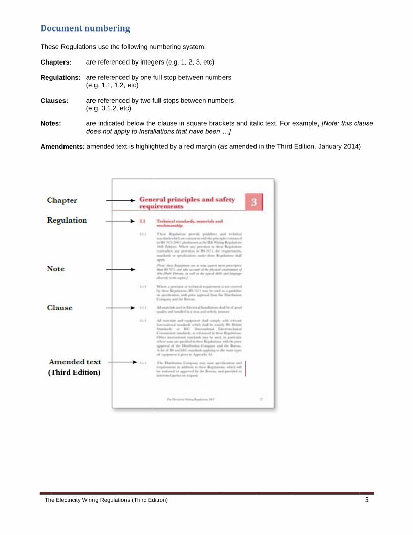
cumentn
se Regulatio
apters:
gulations:
uses:
es:
endments:
Third Edit
Wiring Regulati
numberi
ons use the
are referenc
are referenc(e.g. 1.1, 1.
are referenc(e.g. 3.1.2,
are indicatedoes not ap
amended te
tion)
ions (Third Ed
ng
following nu
ced by integ
ced by one f2, etc)
ced by two fetc)
ed below thepply to Instal
ext is highlig
dition)
umbering sy
gers (e.g. 1,
full stop betw
full stops bet
e clause in sllations that
ghted by a re
ystem:
2, 3, etc)
ween numbe
tween numb
square brackhave been
ed margin (a
ers
bers
kets and ita…]
as amended
lic text. For
in the Third
example, [N
d Edition, Ja
Note: this cla
nuary 2014)
5
ause
)
The Electricity Wiring Regulations (Third Edition) 6
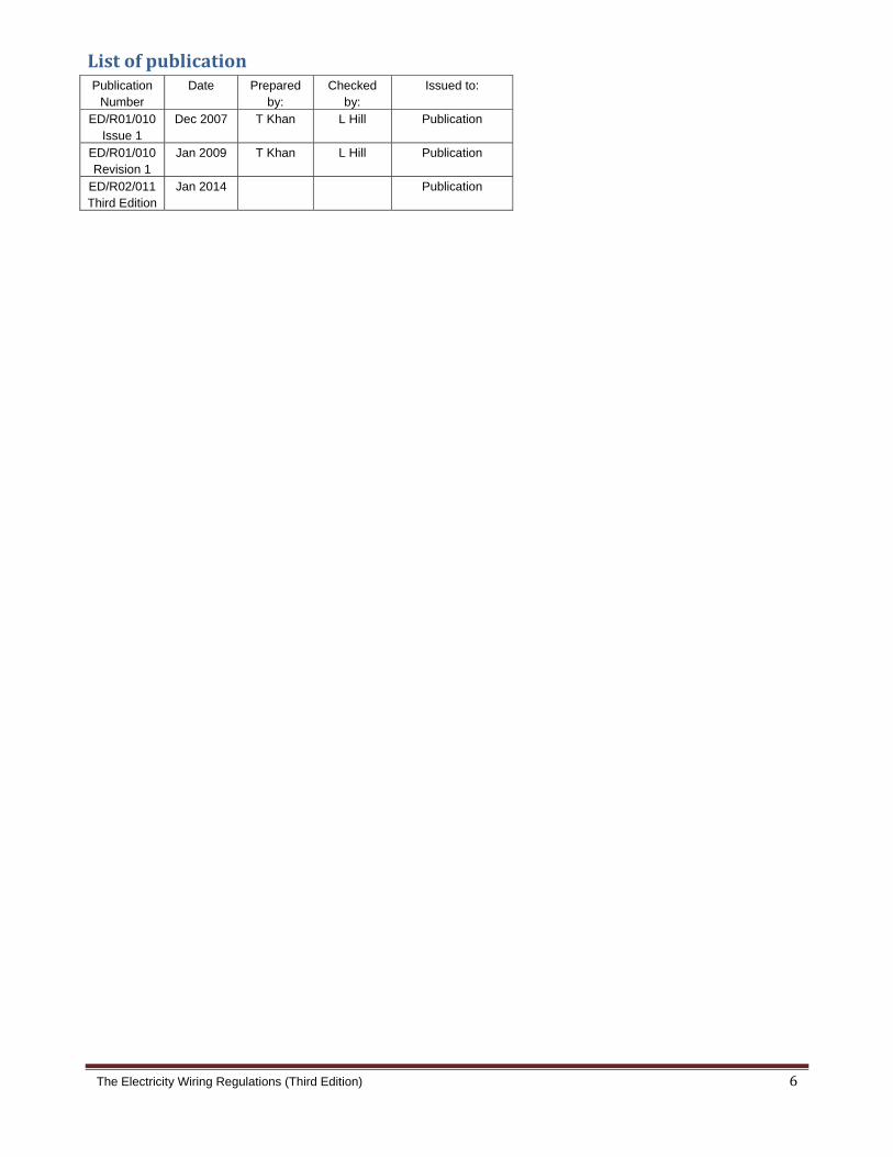
ListofpublicationPublication
Number Date Prepared
by: Checked
by:Issued to:
ED/R01/010 Issue 1
Dec 2007 T Khan L Hill Publication
ED/R01/010 Revision 1
Jan 2009 T Khan L Hill Publication
ED/R02/011 Third Edition
Jan 2014 Publication

The Electricity Wiring Regulations (Third Edition) 7
Tableofcontents Foreword 3 Acknowledgements 4 Document numbering 5 List of publications 6
1 Introduction 10
1.1 Citation and commencement 10 1.2 Purpose and document structure 10 1.3 Scope and enforcement 10
2 Definitions 12
2.1 Interpretation 12
3 General principles and safety requirements 19
3.1 Technical standards, materials and workmanship 19
3.2 Approval of installations 20 3.3 Extensions, alterations and repairs 21 3.4 Licensed contractors 21 3.5 Requirements for safety 22 3.6 Labelling and identification 23 3.7 Environmental conditions 24
4 Electricity parameters and electricity intake 25
4.1 Electricity supply parameters 25 4.2 Electricity intake 25 4.3 The connection point 26 4.4 Multiple occupancy premises 27 4.5 Metering requirements 27
The Electricity Wiring Regulations (Third Edition) 8
5 Protection 28
5.1 General principles 28 5.2 Overload and short-circuit protection 28 5.3 Electric shock protection 29 5.4 Earth leakage protected systems 30 5.5 Earthed equipotential bonded systems 31 5.6 Isolation and switching 33 5.7 Insulation 34
6 Earthing 35
6.1 General principles 35 6.2 Systems of earthing 35 6.3 Main earth terminal 36 6.4 Earth electrodes 36 6.5 Earth conductors 37 6.6 Exposed-Conductive-parts 38 6.7 Earth fault loop impedance 38 6.8 Lightning protection 39 6.9 Functional earthing and high
leakage currents 39
7 Selection of components and installation requirements 40
7.1 Plugs, socket-outlets, and flex outlets 40 7.2 Switches and isolators 41 7.3 Lighting 42 7.4 Conduit, trunking and cable trays 43 7.5 Cables 44 7.6 Final circuits 46 7.7 Busways, bus ducts and busbar risers 47 7.8 Distribution boards 47 7.9 LV switchboards 49
8 Inspection, testing and certification 51
8.1 Inspection and testing 51 8.2 Inspection and testing by the Distribution Company 52 8.3 Electrical installation certificates 52

The Electricity Wiring Regulations (Third Edition) 9
9 Special locations and systems 53
9.1 Separated extra-low voltage (SELV) 53 9.2 Protective extra-low voltage (PELV) 53 9.3 Bathrooms and similar locations 53 9.4 Swimming pools 54 9.5 Water fountains 55 9.6 Temporary electrical installations 56 9.7 Street lighting 57 9.8 External lighting 57 9.9 Marinas and similar locations 58 9.10 Solar photovoltaic (PV) systems 60
10 Power factor correction 63
10.1 General requirements 63 10.2 Specifications for capacitors 63
11 Electric motors and starters 66
11.1 General Requirements 66 11.2 Protection and isolation 66
12 Standby generators 67
12.1 General requirements 67
Appendices 69 Guidance Notes 161
The Electricity Wiring Regulations (Third Edition) 10
Introduction
1.1 Citationandcommencement 1.1.1 These Regulations shall be cited as the Electricity Wiring Regulations (Third Edition).
1.1.2 These Regulations are effective from 1 January 2008. Amendments incorporated in Revision 1
of the Regulations are effective from 1 January 2009. Amendments incorporated in this Third Edition of the Regulations are effective from 1 January 2014.
[Note: Effective from 1 August 2013 the Bureau’s publications will be called ‘Editions’ instead of ‘Revisions’]
1.1.3 These Regulations are issued by the Regulation and Supervision Bureau through the powers
vested in it under Article 62 of Law No (2) of 1998 (as amended). 1.1.4 These Regulations supersede the following regulations:
(a) ADWEA Wiring Rules and Regulations (3rd Edition 2003);
(b) WED Regulations for Electrical Installation Works (1980); and
(c) Earth Leakage Protection Regulations (2001).
1.2 Purposeanddocumentstructure
1.2.1 The purpose of these Regulations is to establish standards and principles that promote the design, construction, installation, maintenance and operation of safe and efficient LV Electrical Installations in all Premises within the Emirate of Abu Dhabi.
1.2.2 The main part of this document is structured into chapters, regulations and clauses, see illustration on page 5. Regulations and clauses are mandatory. Notes which are included below clauses, in italic text, are for guidance, clarification or provide supporting technical information.
1.2.3 The second part of this document consists of Appendices, which contain mandatory information,
and Guidance Notes which contain supporting information.
1.3 Scopeandenforcement 1.3.1 These Regulations apply to all Distribution Companies, Customers, Owners, Licensed
Contractors, or any other persons involved in the design, construction, installation, maintenance or operation of LV Electrical Installations in all Premises within the Emirate of Abu Dhabi. Such locations include, but are not limited to apartments, villas, offices, shops, warehouses, hotels, commercial complexes, leisure complexes, public buildings, parks, farms, temporary Electrical Installations, entertainment arenas, construction sites, tents, outbuildings, caravans, street lighting, and traffic signs. [Note: certain Premises such as industrial, manufacturing, oil and gas etc, due to the nature of their operation, may have specific requirements or standards that are not covered in these Regulations. In such cases evidence of compliance with such requirements or standards must be provided to the relevant Distribution Company.]
1.3.2 The scope of these Regulations does not include the design and technical requirements of the HV and LV electricity distribution networks belonging to Distribution Companies. [Note: requirements governing Distribution Companies’ networks are covered under the Electricity Supply Regulations 2007, as well as relevant Licences, codes and standards.]

The Electricity Wiring Regulations (Third Edition) 11
1.3.3 These Regulations shall apply to all new Electrical Installations constructed following the commencement date (clause 1.1.2). Requirements for extensions, alterations and repairs to existing Electrical Installations are covered under Regulation 3.3. [Note: where the design of an Electrical Installation has been completed before the date of commencement of these Regulations advice must be sought from the Distribution Company before construction is commenced.]
1.3.4 For Electrical Installations constructed before the date of commencement (1 January 2008), the table in Appendix A4(a) lists those clauses that either do not apply or that apply after 1 January 2015 or the date of the next inspection or re-certification (whichever is the earlier).
1.3.5 These Regulations shall be enforced by the relevant Distribution Companies in the Emirate of Abu Dhabi, in accordance with procedures which shall be published by the Distribution Company and approved by the Bureau. See Regulation 3.2.
1.3.6 Compliance with these Regulations requires compliance with other relevant technical standards,
see Regulation 3.1. References to British Standards or other standards means the current edition of the standard cited or its replacement. For existing Electrical Installations clause 1.3.4 applies.
1.3.7 Failure to comply with these Regulations, or any part thereof, shall be deemed as contrary to the
Law and subject to punishment by the imposition of a fine. Any such failures will be addressed in accordance with the Law under Article 65(5) (notices served by the Bureau) and Article 66 (failure to comply and imposition of fines). Action may be taken against any Distribution Company, Customer, Owner, Licensed Contractor or other person to which these Regulations apply. [Note: see Appendix A4(b) for a list of relevant Articles of Law No (2) of 1998.]
1.3.8 Relaxation of any of the requirements of the Regulations shall be approved by the Bureau upon
written request by any Distribution Company, Customer, Owner, Licensed Contractor or other person. Such requests may be referred to a dispensation panel established for such purpose by the Bureau. [Note: relaxation requests from a Customer, Owner, Licensed Contractor or other person must be directed to the relevant Distribution Company in the first instance in accordance with the procedures published by the Company.]
1.3.9 In the event of a dispute between any parties mentioned in clause 1.3.1, the matter may be referred to the Bureau to advise a solution or recommended action. This does not preclude any party referring a matter to the relevant Court of Abu Dhabi.
1.3.10 These Regulations and the rights and duties of any parties thereunder shall be governed by, construed and applied in accordance with, the Laws of Abu Dhabi Emirate and the Federal Laws of the UAE as applied by the Courts of Abu Dhabi.
The Electricity Wiring Regulations (Third Edition) 12
Definitions
2.1 Interpretation Words which are defined under this section are used in the Regulations beginning with capital letters. For example, “all Earth Conductors within a Premises shall be ...”. Terms in common use are not defined here and normal dictionary definitions apply (e.g. circuit-breaker, plug, conduit). Words and expressions other than those described in this section, which are defined in the Law, shall have the meanings ascribed to them in the Law. Words using the singular or plural number also include the plural or singular number, respectively. 2.1.1 Accessory: a device, other than current-using equipment, associated with an Electrical
Installation. 2.1.2 Appliance: an item of current-using equipment. 2.1.3 Arm’s Reach: a zone of accessibility to touch, extending from any point on a surface where a
person may stand or move about, to the limits which such person may reach without assistance (i.e. without any tool or ladder, etc). Such a distance may be taken as 2.5 m height from the standing surface, and 1.25 m horizontally from the standing position.
2.1.4 Bureau: the Regulation and Supervision Bureau for the Water, Wastewater and Electricity
Sector in the Emirate of Abu Dhabi, as established under the Law. 2.1.5 Cable Tray: a cable support consisting of a continuous base with raised edges and no
covering. A cable tray is considered to be perforated where more than 30% of the material is removed from the base.
2.1.6 Cable Trunking: a manufactured enclosure for the protection of cables, normally of rectangular cross-section, of which one side is removable or hinged.
2.1.7 Category 1 Circuit: a Circuit (other than a fire alarm or emergency lighting Circuit) operating at
LV. 2.1.8 Category 2 Circuit: a Circuit (other than a fire alarm or emergency lighting Circuit) which
supplies telecommunications equipment (such as telephones, intruder alarms, data transmission, call bells, etc).
2.1.9 Category 3 Circuit: a fire alarm or emergency lighting Circuit. 2.1.10 Circuit: a set of phase and neutral conductors installed as a group to supply power to a location
and which originate from one Protective Device. The following are related definitions:
a) Ring Circuit: a Circuit which is wired from a single Protective Device, being run through an area to be supplied (via appropriate socket-outlets, switched flex outlets, etc) and returning back to the same Protective Device, thus forming an electrically continuous loop;
b) Radial Circuit: a Circuit which is wired in a ‘radial’ or ‘branch’ configuration, emanating from a Protective Device, to the area to be supplied;
c) Final Circuit: a Circuit which directly supplies Appliances (normally via socket-outlets, switched flex outlets, isolators, ceiling roses, etc.); and
d) Distribution Circuit: a Circuit connecting between Distribution Boards (may also be referred to as a ‘sub-Circuit’).

The Electricity Wiring Regulations (Third Edition) 13
2.1.11 Class I Equipment: equipment which includes a means for connection of Exposed-Conductive-Parts of the equipment to the Earth Conductor, thus providing protection against electric shock in case of failure of the basic insulation of the equipment or other fault condition.
2.1.12 Class II Equipment: equipment which does not include a means for connection to an Earth
Conductor, and which provides supplementary insulation in addition to the basic insulation of the equipment such that a breakdown of the basic insulation will not present a dangerous voltage on Exposed-Conductive-Parts (also known as Double Insulated equipment). Class II Equipment is required to comply with BS 2754. See Appendix A18(b).
2.1.13 Class III Equipment: equipment in which protection against electric shock relies on supply at
SELV and in which voltages higher than SELV are not generated in the equipment, see BS 2754.
2.1.14 Competency Licence: a specific licence issued by a Distribution Company to a Licenced
Contractor assessed as competent for work on LV Electrical Installations. 2.1.15 Connected Load: the aggregate load of Appliances and other electrical equipment at a
Premises, summated using the method described under clause 3.2.7. See Guidance Note G2. 2.1.16 Customer: any person, corporate body, or company who has an agreement with a Distribution
Company for the supply of electricity. 2.1.17 Connection Point (CP): the point which defines the boundary between the Owner’s Electrical
Installation installed at a Premises and the main cable or equipment owned by the Distribution Company.
2.1.18 Danger: risk of injury to people or animals from fire, electric shock, burns, explosion or from
mechanical movement of electrically controlled equipment, or the risk of damage to property. 2.1.19 Direct Contact: the contact with electricity by a person (accidental or otherwise) through the
phase or neutral conductors of an Installation or Appliance, leading to an electric shock, see Guidance Note G4(a).
2.1.20 Distribution Company: a company or body holding a distribution licence, granted by the
Bureau, pursuant to the Law. 2.1.21 Distribution Board: an assembly designed for housing isolation switches and Protective
Devices and for connecting multiple Circuits, including their associated neutral and Earth Conductors. The following are related definitions:
a) Main Distribution Board (MDB): the Distribution Board which accepts the main incoming LV supply from the Distribution Company or Owner’s transformer;
b) Sub Main Distribution Board (SMDB): any Distribution Board which is neither a Main Distribution Board nor a Final Distribution Board; and
c) Final Distribution Board (FDB): a Distribution Board which supplies Final Circuits only.
2.1.22 Diversified Load: the load at a Distribution Board, at the Electricity Intake or at any other point
in an Electrical Installation, calculated using diversity factors as illustrated in Guidance Note G2. 2.1.23 Double Insulated Equipment: see Class II Equipment. 2.1.24 Earth: the conductive mass of Earth, whose electrical potential (voltage) at any point is
conventionally taken as zero. The following are related definitions:
(a) Locally Earthed System (TT): a system of supply where the Owner provides a Main Earth Terminal for the Electrical Installation, which is connected to a sufficient number of local Earth

The Electricity Wiring Regulations (Third Edition) 14
Electrodes to provide a maximum Earth Resistance measured at the Owner’s Main Earth Terminal of not more than 10 Ohms.
(b) Distribution Company Earthed System (TN-S): a system of supply where the Distribution Company provides a connection to the Owner’s Main Earth Terminal, using the distribution network Earthing system.
2.1.25 Earthing or Earthed: a general term used to describe the connection of conductive parts of an Electrical Installation or an Appliance to Earth.
2.1.26 Earth Conductor: a conductor used to connect Exposed-Conductive-Parts of an Electrical Installation and associated Appliances to Earth, and providing a means for the safe passage of earth fault current. This includes the following defined terms:
(a) Main Earth Conductor (MEC): conductors connected between Earth Electrodes and Main Earth Terminals; and
(b) Circuit Earth Conductor (CEC): conductors connecting all circuits emanating from Main Distribution Boards, Sub Main Distribution Boards, Final Distribution Boards including Circuits connecting to equipment and Appliances. Outside these Regulations these may also be known as the Circuit Protective Conductor (CPC) or Earth Continuity Conductor (ECC).
2.1.27 Earth Electrode: a conductor or group of conductors in intimate contact with Earth, providing
an electrical connection to Earth, and normally having a known and measurable value of Earth Resistance.
2.1.28 Earthed Equipotential Bonding (EEB): the connection of Extraneous-Conductive-Parts within
a Premises using designated conductors such that potential Touch Voltages are kept to a safe value during the passage of earth fault current (also known outside these Regulations as ‘PME Bonding’). This definition includes the following:
(a) Main Equipotential Bonding: the connection of major Extraneous-Conductive-Parts, such as pipe services and metallic structures, at their point of entry into a Premises to the Main Earth Terminal in an Installation, using designated conductors.; and
(b) Supplementary Equipotential Bonding: the connection of Extraneous-Conductive-Parts with each other or with Exposed-Conductive-Parts within an area where such parts are simultaneously accessible to persons, such that the potential Touch Voltage during an earth fault is kept to safe limits.
[Note: for disconnection times greater than 0.4 seconds a safe Touch Voltage limit may be taken as 50 V for dry conditions and 25 V for wet conditions.]
2.1.29 Earthed Equipotential Bonded System (EEBS): a system where protection against electric shock due to Indirect Contact is achieved by the provision of Earthed Equipotential Bonding conductors, in association with Protective Devices for the automatic disconnection of supply.
2.1.30 Earth Leakage Protection (ELP): the provision of protection against electric shock due to
Indirect Contact by the use of RCDs or other sensitive earth leakage protective devices which automatically disconnect the supply sufficiently quickly so as to prevent danger to persons.

The Electricity Wiring Regulations (Third Edition) 15
2.1.31 Earth Leakage Protected System (ELPS): a system of supply where Earth Leakage Protection is provided on Final Circuits and an additional ELP is provided at the Electricity Intake.
2.1.32 Earth Resistance: the resistance (in Ohms) from any point on an Electrical Installation to
Earth, being measured using an approved testing device and approved procedure. 2.1.33 Earth Fault Loop Impedance (Zs): the total impedance presented to an earth fault current,
comprising the impedance of the following parts of a system, illustrated in Appendix A5(g):
(a) the Circuit Earth Conductor;
(b) the Main Earth Terminal; (c) the main Earth Conductors connecting to Earth Electrodes or the Distribution Company
Earth;
(d) the path of earth fault current through the general mass of Earth, or through the conductors or earth sheath or armouring of the Distribution Company cable;
(e) the neutral earth connection(s) of the Distribution Company;
(f) the distribution transformer winding; and
(g) the phase conductor of the Circuit back to the point of fault. 2.1.34 Electricity Intake: a term used to describe the location or room housing the Main Distribution
Board and/or the main cable and equipment owned by a Distribution Company to which the Electrical Installation of the Premises is connected via a defined Connection Point.
2.1.35 Electrical Installation: an Electrical Installation comprises any fixed or temporary cable, switchgear, or other electrical equipment or apparatus within a Premises or other place where there is an electricity supply (including outdoor locations). Fixed or portable electrical Appliances are not considered part of the Electrical Installation, although these Regulations do include requirements for the connection of Appliances (e.g. plugs and socket-outlets).
2.1.36 Electrical Installation Certificate: a certificate in the format indicated in these Regulations
which is issued by a Licensed Contractor after completion of work on an Electrical Installation and provided to the Customer or Owner of the Premises.
2.1.37 Electricity Distribution Code: a code prepared and maintained by the Distribution Companies detailing technical parameters and other requirements relating to the connection and the use of the distribution networks owned and operated by the Distribution Companies.
2.1.38 Exposed-Conductive-Part: a conductive part of an Electrical Installation or Appliance which
can be touched by persons and which is not normally live but may become live due to a fault condition. Exposed-Conductive-Parts are required to be connected to Earth, see Regulation 6.6.
2.1.39 Extraneous-Conductive-Part: a conductive part, structure or any metalwork within a Premises which is not part of, and is unrelated to, the Electrical Installation and which is not designed to carry current, but which may become live due to a fault condition. Extraneous-Conductive-Parts are required to be connected to Earth for Electrical Installations or parts of Electrical Installations classified as Earthed Equipotential Bonded Systems, see Regulation 5.5.

The Electricity Wiring Regulations (Third Edition) 16
2.1.40 Extra-Low Voltage (ELV): see Voltage. 2.1.41 Final Circuit: see Circuit. 2.1.42 Functional Earth: an Earth or Earthing system which is provided for special functions (such as
reduction of radio frequency interference, noise filtering for computers, etc) and which is separate from other Earth Conductors in an Electrical Installation but is connected to the Main Earth Terminal.
2.1.43 High Voltage: see Voltage. 2.1.44 Indirect Contact: contact of a person with electricity through Exposed-Conductive-Parts of an
Electrical Installation or Appliance, or through Extraneous-Conductive-Parts in a Premises which have become live during fault conditions, see Guidance Note G4(b).
2.1.45 Law: means Law No (2) of 1998 Concerning the Regulation of the Water, Wastewater and
Electricity Sector in the Emirate of Abu Dhabi (as amended). 2.1.46 Licensed Contractor: a person, entity or company which has been assessed by the
Distribution Company as competent to work on Electrical Installations and issued a Competency Licence by that Distribution Company.
2.1.47 Low Voltage: see Voltage. 2.1.48 Luminaire: equipment which is designed to house one or more electric lamps and which may
include diffusers, fixtures, transformers and auxiliary Circuits but is taken to exclude the lamps themselves. Outside of these Regulations a Luminaire may commonly be referred to as a ‘light fitting’.
2.1.49 Main Distribution Board: see Distribution Board. 2.1.50 Main Earth Terminal (MET): the main connection point at which the nominal value of Earth
Resistance for an Electrical Installation is taken, and to which Earth Conductors from Earth Electrodes or the Distribution Company Earth are connected. This will normally be at or close to the Connection Point.
2.1.51 Marina: a facility for the mooring of Leisure Craft which has fixed wharves, jetties, piers or a pontoon arrangement capable of berthing one or more Leisure Craft. The following are related definitions:
(a) Leisure Craft: a boat, vessel, yacht, motor launch, houseboat or other floating craft used
exclusively for sport or leisure; and
(b) Pedestal: an electrical service enclosure providing electricity connection to Leisure Crafts in
Marinas.
2.1.52 Owner: the legal owner of the Premises in which an Electrical Installation is installed.
2.1.53 Premises: any occupied or unoccupied land, structure, building, enclosure or other place. Such locations include, but are not limited to, apartments, villas, offices, shops, warehouses, hotels, commercial complexes, leisure complexes, public buildings, parks, farms, temporary Electrical Installations, entertainment arenas, construction sites, tents, outbuildings, caravans, street lighting and traffic signs.
2.1.54 Prospective Fault Current: the value of current that would flow due to a short-circuit fault of
negligible impedance between live phase conductors, or between phase conductors and Earth. The maximum Prospective Fault Current for an Electrical Installation is normally taken at the Connection Point.

The Electricity Wiring Regulations (Third Edition) 17
2.1.55 Protective Device: a device installed at the start of a Circuit which will automatically disconnect the input of electricity in the event of a fault or overload occurring on that Circuit. Such devices include, but are not limited to, fuses, fuse links, miniature circuit-breakers (MCB), moulded case circuit-breakers (MCCB) and residual current devices (RCD).
2.1.56 PV: Solar photovoltaic.
(a) a.c. side: part of a PV installation from the a.c. terminals of the PV Inverter to the point of
connection of the PV supply cable to the Electrical Installation;
(b) Array: Mechanically and electrically integrated assembly of PV Modules, and other
necessary components, to form a d.c. power supply unit;
(c) Array Junction Box: Enclosure where PV Strings of any PV Array are electrically
connected and where devices can be located;
(d) d.c. side: part of a solar PV system installation from a PV cell to the d.c. terminals of the PV
Inverter;
(e) Inverter: Device which converts d.c. voltage and d.c. current into a.c. voltage and a.c.
current;
(f) Module: Smallest completely environmental protected assembly of interconnected PV cells;
(g) Open-Circuit Voltage, Voc: voltage under standard test conditions across unloaded (open)
PV Module, PV String, PV generator, or on the d.c. side of the PV Inverter;
(h) Short Circuit Current, Isc: short circuit current of a PV Module, PV String, PV Array or PV
generator under standard test conditions; and
(i) String: Circuit in which PV Modules are connected in series, in order for a PV Array to
generate the required output voltage.
2.1.57 Radial Circuit: see Circuit. 2.1.58 Residual Current Device (RCD): a Protective Device which is installed to automatically isolate
the supply to a Circuit or Distribution Board when the vector sum of currents in the phase and neutral conductors reaches a preset value (referred to as the residual operating current or residual current rating).
2.1.59 Ring Circuit: see Circuit. 2.1.60 Sub Main Distribution Board: see Distribution Board. 2.1.61 Touch Voltage: the Voltage that would appear during an earth fault condition between
Exposed-Conductive-Parts and Extraneous-Conductive-Parts which are simultaneously accessible to persons.
[Note: this term is used only in connection with protection against Indirect Contact and is not used to refer to Direct Contact with electricity. The seriousness of impact of Touch Voltage on a person will depend on the body resistance and the immediate surroundings, in particular the presence of water. See Guidance Note G4(h) and G5(b).]

The Electricity Wiring Regulations (Third Edition) 18
2.1.62 Voltage:
(a) High Voltage (HV): an a.c. voltage greater than Low Voltage and less than 36 kV between phases or 21 kV between any phase and Earth (internationally referred to as Medium Voltage);
(b) Low Voltage (LV): an a.c. voltage below 1000 V between phases, or below 600 V between any phase and Earth or, a d.c. voltage below 1500 V between conductors, or below 900 V between any conductor and Earth;
(c) Extra-Low Voltage (ELV): a voltage not exceeding 50 V a.c. or 120 V d.c. whether between live conductors or between live conductors and Earth;
(d) Separated Extra-Low Voltage (SELV): an Extra-low Voltage system which is electrically separated from Earth in such a way that a single fault cannot give rise to the risk of electric shock;
(e) Protective Extra-Low Voltage (PELV): a system which has the same features as SELV except that connection of Exposed-Metallic-Parts to Earth is allowed; and
(f) Reduced Low Voltage (RLV): a voltage which does not exceed 55 V a.c. between phase and Earth or 110 V a.c. between phases.

The Electricity Wiring Regulations (Third Edition) 19
Generalprinciplesandsafetyrequirements
3.1 Technicalstandards,materialsandworkmanship 3.1.1 These Regulations provide guidelines and technical standards which are consistent with the
principles contained in BS 7671:2008 (also known as the IEE Wiring Regulations 17th Edition). Where any provision in these Regulations contradicts any provision in BS 7671, the requirements, standards or specifications under these Regulations shall apply.
[Note: these Regulations are in some aspects more prescriptive than BS 7671, and take account of the physical environment of Abu Dhabi Emirate, as well as the typical skills and language diversity in the region.]
3.1.2 Where a provision or technical requirement is not covered by these Regulations, BS 7671 may
be used as a guideline or specification, with prior approval from the Distribution Company and the Bureau.
3.1.3 All materials used in Electrical Installations shall be of good quality and installed in a neat and
orderly manner. 3.1.4 All materials and equipment shall comply with relevant international standards which shall be
mainly BS (British Standards) or IEC (International Electrotechnical Commission) standards, as referenced in these Regulations. Other international standards may be used, in particular where none are specified in these Regulations, with the prior approval of the Distribution Company and the Bureau. A list of BS and IEC standards applying to the main types of equipment is given in Appendix A3.
3.1.5 The Distribution Company may issue specifications and requirements in addition to these
Regulations, which will be endorsed or approved by the Bureau, and provided to interested parties on request. The Distribution Company shall ensure that any such specifications or requirements are consistent with these Regulations, unless otherwise approved by the Bureau.
3.1.6 Reference must be made, where relevant, to UAE or Gulf standards which may be issued from
time to time by the Emirates Standardisation and Metrology Authority (ESMA).
The Electricity Wiring Regulations (Third Edition) 20
3.2 Approvalofinstallations 3.2.1 Any Owner requiring a new connection or alteration to an existing connection must make an
application to the Distribution Company using the appropriate forms and procedure published by the Company.
3.2.2 The design of an Electrical Installation must be approved by the Distribution Company before
commencement of construction. Details of the design must be submitted, together with appropriate calculations and wiring diagrams, using the standard symbols shown in Appendix A11.
[Note: even though the relevant Distribution Company approves Electrical Installations, this does not relieve the Owner and associated Licensed Contractor from the obligation to fully comply with these Regulations.]
3.2.3 For large developments, the Owner may, with the prior approval of the Bureau and the
Distribution Company, enter into an undertaking with the Distribution Company to the effect that all parts of an Electrical Installation downstream from the Connection Point shall comply with these Regulations. Any such approval, including as to the form of undertaking, will be at the discretion of the Bureau and the Distribution Company. If given, the Owner will not be required to submit details of the Electrical Installation design to the Distribution Company for prior approval. A decision by the Bureau and the Distribution Company to allow the Owner to self-certify the design of an Electrical Installation shall not have any bearing on any inspection of the Electrical Installation by the Distribution Company, and the Owner shall rectify any non-compliance identified by the Distribution Company (either in the pre-energisation inspection or upon any other inspection) at its own cost and within the timeframes specified by the Distribution Company or set out in these Regulations.
3.2.4 Notwithstanding Clause 3.2.3, in all instances the Owner and associated Licensed Contractor are responsible for ensuring that the design, construction and installation of Electrical Installations complies with these Regulations.
3.2.5 New Electrical Installations must be inspected and tested by the Distribution Company in accordance with the requirements of Chapter 8 of these Regulations, prior to and upon energisation.
3.2.6 The Distribution Company may, where appropriate, seek evidence of compliance against relevant standards of equipment and components used in the Electrical Installation.
3.2.7 The Owner must provide an estimate of the Connected Load at the Premises, including at each
Distribution Board. In addition, the Diversified Load for the whole Premises and at each Distribution Board, must be calculated by the Owner’s appointed Licensed Contractor (i.e. design engineer or other qualified person) and submitted in the format given in Appendix A20(e), see Guidance Note G2.

The Electricity Wiring Regulations (Third Edition) 21
3.3 Extensions,alterationsandrepairs 3.3.1 No extension or alteration to an Electrical Installation may be made without prior notification to
the Distribution Company or without approval, testing and certification in accordance with Regulation 3.2.
3.3.2 All extensions or alterations to an existing Electrical Installation must comply with the
requirements of these Regulations. 3.3.3 Notwithstanding clause 3.3.1 and 3.3.2, repairs to existing Electrical Installations may be made
using standards of equipment compliant with the original Electrical Installation, but limited to work of an essential nature on a like-for-like basis. Work on any part of the Electrical Installation other than Final Circuits, including any Distribution Board and any items at the Electricity Intake, must be notified to the Distribution Company.
3.3.4 Any proposed increase greater than 10% of the total Connected Load at a Premises, or greater
than 10% of the Connected Load at any Distribution Board, must be approved by the Distribution Company.
3.4 Licensedcontractors 3.4.1 Work on Electrical Installations may only be carried out by Licensed Contractors who have been
assessed and approved by the Distribution Company. 3.4.2 The process for approval of Licensed Contractors shall be published by the Distribution
Company and approved by the Bureau. 3.4.3 A register of Licensed Contractors shall be kept up-to-date by the Distribution Company and
provided on request to any person.
The Electricity Wiring Regulations (Third Edition) 22
3.5 Requirementsforsafety 3.5.1 The provisions of these Regulations require that all Electrical Installations are designed and
constructed so as to ensure the safety of all persons who may operate, maintain or otherwise use or be affected by any part of an Electrical Installation. In addition to the requirements detailed under the relevant sections of these Regulations, the following general safety principles shall apply.
[Note: these Regulations do not include detailed requirements for the maintenance of Electrical Installations. However, the maintainability of Electrical Installations must be adequately catered for in their design and construction. In addition the requirements for periodic inspection and testing, as detailed in Chapter 8, may give rise to the need for maintenance and repair work.]
3.5.2 All parts of an Electrical Installation shall be designed and constructed so as to prevent Danger. 3.5.3 All parts of an Electrical Installation shall be sufficiently sized and rated to safely carry out the
function for which they are required. 3.5.4 All parts of an Electrical Installation shall be insulated appropriate to the function they serve, in
consideration of the expected operating environment, so as to prevent Danger.
[Note: for areas classified as explosive or flammable, the requirements of BS EN 60079 shall be satisfied.]
3.5.5 All Exposed-Conductive-Parts of an Electrical Installation and of Appliances must be connected
to Earth via appropriate Earth Conductors, so as to protect against electric shock, see Regulation 6.6.
3.5.6 Except in specified circumstances, all Electrical Installations shall be provided with Earth
Leakage Protection at the source of supply, at all Final Circuits and at other appropriate points, see Regulation 5.3.4.
3.5.7 All Electrical Installations must be protected against damage caused by excess current due to a
fault or overload by suitable Protective Devices, see Regulation 5.2. 3.5.8 All Electrical Installations must be provided with a means of isolating the electricity supply at
suitable sections, subsections and Circuits, and at points where Appliances are used, see Regulation 5.6.
3.5.9 All parts of an Electrical Installation must be suitably located so as to provide safe access for
operation, maintenance and repair and must be protected against accidental or deliberate interference or damage.
3.5.10 Electrical Installations must be designed and constructed with particular consideration given to
the risk of fire due to electrical faults and the propagation of fire through parts of the Electrical Installation. See clauses 6.1.1(c), 7.2.4, 7.4.5, 7.4.15, 7.5.3, 7.5.4, 8.2.1(g) and 11.2.1.
3.5.11 All Electrical Installations must be inspected and tested at the time of first commissioning and at
regular intervals thereafter to ensure ongoing safety, as detailed under Chapter 8 of these Regulations.
3.5.12 Inspection and testing of Electrical Installations must be carried out with due skill and care to
avoid Danger to persons, property and installed equipment. 3.5.13 Additional requirements for safety in special locations are covered in Chapter 9.

The Electricity Wiring Regulations (Third Edition) 23
3.6 Labellingandidentification 3.6.1 Electrical Installations at the Electricity Intake room must be suitably labelled so as to give
information on the electricity supply parameters, the source of supply, location in relation to other Electrical Installations, assets ownership, authorised personnel contact details and any special precautions to be taken. See example in Appendix A12(a).
[Note: special precautions would include information on other sources of electricity such as local generation or interconnection with other Premises.]
3.6.2 The means of isolation from all sources of electricity must be clearly labelled and accessible to
authorised persons, see Regulation 5.6. 3.6.3 The provision of Earth Leakage Protection (as required under Regulation 5.3.4) must be clearly
indicated at appropriate isolation points, including a notice informing Owners of the need for regular testing of RCD devices, see Appendix A12(c).
3.6.4 Individual Circuits (including neutral and Earth Conductors) must be identified by numbering at
the source end and, where appropriate, at intervals along the route, see Guidance Note G7(f). 3.6.5 For non-domestic Electrical Installations, all accessories and fittings must be marked with
Circuit identification numbers.
[Note: Circuit identification numbers must indicate the Distribution Board from which an Accessory or fitting is supplied, and may be fixed externally or internally, i.e. either outside or inside cover plates.]
3.6.6 Load distribution schedules, as shown in Appendix A20(e), must be provided at each
Distribution Board. An overall wiring diagram showing the Connection Point(s), the location and interconnection of Distribution Boards must be provided at the Electricity Intake.
3.6.7 Where parts of an Installation are accessible or visible to the general public they must be
labelled with a warning: “LIVE – 230/400 VOLTS – DANGER OF DEATH” or similar wording. This warning must be written in English and Arabic, see example in Appendix A12(a). However, parts of final Circuits and other points of normal use may be excluded from this requirement.
The Electricity Wiring Regulations (Third Edition) 24
3.7 Environmentalconditions 3.7.1 All parts of an Electrical Installation must be suitably designed, constructed and maintained so
as to operate safely and carry out their designed function in the expected operating environment. The following environmental conditions may be used as a guide if no other special factors apply:
(a) maximum ground temperature (at 1 m depth): 35˚C;
(b) soil resistivity: according to local conditions;
(c) weather: mainly sunny, occasional fog (causing condensation on outdoor equipment), and occasional sandstorms;
(d) air quality: frequently dusty, corrosive in coastal areas;
(e) maximum humidity: 100%;
(f) maximum ambient (air) temperatures:
outdoor (shaded): 50˚C
outdoor (unshaded): temperature rise due to solar gain must be calculated for the relevant equipment or the maximum ‘black bulb’ temperature may be used (typically 10 ˚C above ambient temperature)
indoor (not air conditioned): 40˚C
indoor (air conditioned): 30˚C
[Note: in some situations the ambient temperature for indoor non-air-conditioned situations may reach the outdoor shaded temperature e.g. a small prefabricated building with little ventilation, or a garage which is open to the atmosphere.]
The Electricity Wiring Regulations (Third Edition) 25
Electricityparametersandelectricityintake
4.1 Electricityparameters 4.1.1 The parameters for electricity supplies provided in the Emirate of Abu Dhabi are defined in the
Electricity Supply Regulations 2007, issued by the Bureau.
Voltage and frequency 4.1.2 The nominal voltage at LV shall be 230 V single-phase or 400 V three-phase.
4.1.3 The permissible variation from the nominal voltage shall be kept within + 10% and - 6%. 4.1.4 The nominal frequency shall be 50 Hz.
Harmonics, voltage disturbances and power factor 4.1.5 Electrical Installations, and the use of electrical equipment therein, must be designed to avoid
the generation of disturbances in the electricity supply voltage. These may include voltage fluctuations, voltage dips, voltage unbalance and harmonics, which are of a magnitude that adversely affect the Customers of the Distribution Company.
4.1.6 The permitted limits of such disturbances are given in the Electricity Distribution Code, Annex 1.
Owners will be required to install filters or other equipment to mitigate against such disturbances that are outside the permitted limits (as explained in the Electricity Distribution Code).
4.1.7 The power factor at the Connection Point between the Distribution Company and the Owner’s
Electrical Installation must be maintained between 0.9 lagging and unity. Power factor correction equipment must be used where required to achieve this value, see Chapter 10.
Prospective fault current 4.1.8 The maximum three-phase Prospective Fault Current at LV shall be 46 kA (1 second) at the LV
busbar of the Distribution Company’s HV/LV substation, or 30 kA (1 second) at a LV feeder pillar, or 25 kA (1 second) at a LV service turret or such lower value as otherwise agreed between the Distribution Company and the Owner.
4.2 Electricityintake 4.2.1 The Electricity Intake must be positioned in a dedicated room or housing and would typically be
made from concrete block, brick or similar construction. [Note: where prefabricated enclosures are used, the enclosures must be verified in accordance with the relevant international standards and be approved by the Distribution Company prior to installation]
4.2.2 Other than in exceptional circumstances, and with prior approval from the Distribution Company, there shall be only one Electricity Intake for any Premises.
4.2.3 The Electricity Intake must be positioned in an area which is readily accessible to Distribution
Company staff and other authorised persons, particularly in an emergency, and must be at or close to the outside perimeter of a Premises.
4.2.4 The Electricity Intake must not be positioned in an area controlled by one of the tenants in a

The Electricity Wiring Regulations (Third Edition) 26
multi-occupancy building. 4.2.5 Equipment at the Electricity Intake must be located in a safe and accessible position, and kept
clear of hindrance at all times. 4.2.6 The use of Electricity Intake rooms as storage rooms for any tools, equipment or other materials
is prohibited. 4.2.7 The Electricity Intake must not be located on the reverse side of a bathroom or kitchen wall, or
below a bathroom or kitchen. The Electricity Intake must not be located below any water services or pipes, such as mains water supply, drainage systems, storage tanks, air conditioning chillers, or other liquids or hazardous materials.
4.2.8 The Electricity Intake room must be well ventilated, preferably without the need for forced air
circulation. Where air conditioning is required in the Electricity Intake room the requirement for fresh air circulation must also be provided to avoid condensation [Note: consideration must be given to the relevant UAE fire code requirements.]
4.2.9 At least one emergency lighting unit must be fitted in all Electricity Intake rooms, which must be
provided with a battery rated for minimum 3 hours illumination, and subject to adequate routine maintenance.
4.2.10 Doors to Electricity Intake rooms must be arranged to open outwards, be kept free from
obstructions, and be capable of being opened from the inside without the use of a key. 4.2.11 The need for delivery of heavy equipment to the Electricity Intake room during construction and
for future repair or alterations must be taken into account in the location of the Electricity Intake room.
4.2.12 For Electricity Intake rooms of greater than 6 m in length more than one door shall be provided
as a means of emergency access. 4.2.13 Electrical Installation layouts and minimum sizes of the Electricity Intake are given in Appendix
A12(b) and A12(d). 4.2.14 For large Electrical Installations the Electricity Intake may contain one or more LV switchboards,
the requirements for which are given in Regulation 7.9. 4.2.15 Where a HV/LV substation is required within the Premises, the design and construction
requirements for the substation will be specified by the Distribution Company.
4.3 Theconnectionpoint 4.3.1 Equipment at the Connection Point must be locked or sealed by the Distribution Company to
prevent deliberate or accidental interference. Such locks or seals will include those for metering equipment, etc.
4.3.2 The Owners’ Main Distribution Board must always include a means of emergency isolation in
the case of a fault or breakdown (e.g. main circuit-breaker) which is readily accessible and clearly labelled so as to be easily operated by the Owner. Such means of emergency isolation must be left unlocked at all times, except when locked in the open position to allow access to the Electrical Installation (e.g. for maintenance).
The Electricity Wiring Regulations (Third Edition) 27
4.4 Multipleoccupancypremises 4.4.1 Individual Customers within multiple occupancy Premises may be supplied by the Premises
Owner’s Electrical Installation consisting of rising and lateral mains (cabling or busbars). Rising and lateral mains will normally be owned and operated by the Premises Owner.
4.4.2 The electricity metering for individual Customers for a rising or lateral mains system will
normally be at the point nearest to each Customer, remote from the main Electricity Intake. 4.5 Meteringrequirements 4.5.1 The requirements for Customer metering are contained in the Customer Metering Regulations
2005, issued by the Bureau. Additional detailed requirements and procedures will be provided by the Distribution Company where required.
The Electricity Wiring Regulations (Third Edition) 28
Protection
5.1 Generalprinciples 5.1.1 All Electrical Installations and individual circuits therein must be designed, constructed and
maintained to provide protection against the following:
(a) overload; (b) short-circuits (phase to phase or phase to Earth); and (c) electric shock (due to Direct or Indirect Contact with electricity).
5.1.2 Protection against conditions of overload and short-circuit will normally be provided by MCBs,
MCCBs or similar devices, see Regulation 5.2 below.
5.1.3 Protection of persons against electric shock due to Direct Contact or Indirect Contact must be provided by one of the methods detailed in Regulation 5.3 below.
[Note: see Guidance Note G4(a) and G4(b) for explanation of Direct and Indirect Contact.]
5.2 Overloadandshort‐circuitprotection 5.2.1 All Electrical Installations and individual Circuits therein must be provided with devices that
protect against thermal, electromagnetic and other detrimental effects caused by overload and short-circuits. Such devices must be located at suitable sections and Circuits so as to give effective automatic disconnection in such conditions.
5.2.2 The main circuit-breaker at the Connection Point must be of MCCB or ACB type and adequately
rated for the maximum Prospective Fault Current. 5.2.3 All Circuits must be individually protected against overloads and short-circuits by suitable
devices. Replaceable or re-wireable fuse links are not permitted for this purpose.
5.2.4 The time-current performance characteristics of Protective Devices must conform to the relevant reference standards listed in Appendix A3.
[Note: the time-current performance curves for MCBs are shown in Appendix A6(a) – (d).]
5.2.5 To ensure protection against overload, Circuit conductors must be sized taking into account the time-current characteristic of the Protective Device.
[Note: see note 2 of Appendix A6(f).]
5.2.6 Protective Devices at the Main Distribution Board must have a Prospective Fault Current withstand and interruption rating above the maximum Prospective Fault Current declared by the Distribution Company for the relevant Connection Point.
5.2.7 Protective Devices downstream of the Main Distribution Board may have a reduced Prospective
Fault Current withstand and interruption rating, taking into account the ‘energy let-through’ characteristic (I2t) of the upstream Protective Device, see Appendix A6(e). Where appropriate, an allowance may also be made for the attenuation of Prospective Fault Current due to the Circuit impedance.
The Electricity Wiring Regulations (Third Edition) 29
5.3 Electricshockprotection
Direct contact 5.3.1 Protection of persons against the risk of Direct Contact with electricity must be provided by
either physically preventing contact or by an inherently safe systems of supply, using one or more of the following measures:
(a) insulated conductors, see Regulation 5.7;
(b) secure enclosures, barriers or covers on live parts;
(c) Separate Extra-Low voltage (SELV) system; or
(d) Protective Extra-Low Voltage (PELV) system.
[Note: SELV conductors at voltages of 12 V a.c. or 30 V d.c. may be un-insulated but must be provided with overload and short circuit protection.]
5.3.2 Residual Current Devices with a residual current rating of 30 mA and complying with BS EN
61008 and BS IEC 1008 may be used as a means of supplementary protection against Direct Contact. However, RCDs may not be used as the sole means of protection against Direct Contact i.e. one of items (a) to (d) above must be used in addition to RCD protection. [Note: RCD devices with a residual current rating above 30 mA are not considered to provide adequate protection against Direct Contact but may be used to provide protection against Indirect Contact – see Regulation 5.4. It should be noted that RCD devices do not protect against electric shock between phase conductors or between phase conductors and neutral.]
Indirect Contact 5.3.3 Indirect Contact with electricity can occur when a voltage appears on Earthed parts of an
Electrical Installation or Appliance due to the passage of earth fault current and whilst a person is in contact with either:
(a) an Exposed-Conductive-Part and an Extraneous-Conductive-Part; or
(b) an Exposed-Conductive-Part and Earth; or
(c) an Extraneous-Conductive-Part and Earth.
5.3.4 Protection against the risk of electric shock in the above cases must be provided by:
(a) an Earth Leakage Protected System, where RCDs or similar devices are provided at Final Circuits and additional RCDs or other sensitive Earth Leakage Protection is provided at the Electricity Intake, see Regulation 5.4; and
(b) an Earthed Equipotential Bonded System, see Regulation 5.5.

The Electricity Wiring Regulations (Third Edition) 30
5.4 Earthleakageprotectedsystems 5.4.1 An Earth Leakage Protected System (ELPS) is defined as one where protection against Indirect
Contact is provided by the use of RCDs or other similar devices on all Final Circuits and ELP is provided at the Electricity Intake. Such a system is required to automatically disconnect the supply at a Final Circuit or at the Electricity Intake sufficiently quickly so as to prevent Danger.
5.4.2 For Final Circuits, ELP devices must be of the RCD type whereby the device will trip if the
vector sum of currents carried by the phase and neutral conductors is above a preset value, see Guidance Note G5(c). Voltage-operated earth leakage devices (ELCB) are not permitted.
5.4.3 RCD devices for Final Circuits must have a time-current performance characteristic complying
with BS EN 61008 and BS IEC 1008. This requires that the device must operate within 200 milliseconds at its residual current rating and within 40 milliseconds at 5 times its residual current rating. It must not operate below 50% of its residual current rating, see Guidance Note G5(a).
[Note: Earth Leakage Protection devices provide protection against electric shock by limiting the time that current may pass through the body of a person to Earth; they do not limit the magnitude of current, except by the feature of early cut-off for a rising current. In addition, ELP devices provide protection against ‘high resistance’ earth faults that may persist in an Electrical Installation if the fault current is too low to operate overcurrent devices such as MCBs. Such faults may cause overheating of Circuits or connections and lead to a fire.]
5.4.4 For Final Circuits which are liable to carry pulsating or d.c. currents RCD devices must be of
type A (pulsating d.c. sensitivity) and for RCD devices requiring time-delayed operation type S devices must be used, see Guidance Note G5(d).
5.4.5 Earth Leakage Protection provided at the Electricity Intake must be set to discriminate with
RCDs at Final Circuits (i.e. earth faults on Final Circuits must be automatically disconnected by the closest RCD). See Appendix A5(m) and Guidance Note G4(e).
[Note: such discrimination may be provided by time-delayed RCD’s, earth fault relays or other suitable devices at each LV panel or circuit breaker at the Electricity Intake. ELP is not required at Sub Main Distribution Boards but, if provided, must discriminate with ELP devices on upstream and downstream Circuits.]
5.4.6 The operating current setting for ELP devices at the Electricity Intake must take into account the nature of the Electrical Installation (e.g. commercial, industrial, etc), the likelihood and magnitude of earth fault currents, and the requirement for protection against Indirect Contact, see Appendix A5(m) and Guidance Note G4(f).
[Note: where the Electricity Intake consists of a multi-panel LV switchboard, each panel or circuit breaker should be fitted with ELP devices in order to limit the extent of power interruptions. The ELP device for the incomer panel must discriminate with the outgoing panels / circuits.]
5.4.7 At each Distribution Board or other point where a RCD is provided a suitable label must be
affixed to inform the Owner of the characteristics and mode of operation of the device and the need for routine testing, see Appendix A12(c).
5.4.8 For domestic Premises the residual current rating for RCDs must be no greater than 100 mA for
Final Circuits supplying fixed equipment (e.g. lighting and air conditioning) and no greater than 30 mA for Final Circuits where Appliances may be used by persons (e.g. all socket-outlets, all kitchen Appliances, other Appliances accessible to persons), and no greater than 30 mA for all Circuits in a bathroom, see Regulation 9.3. A full list of applications and residual current ratings is provided in Appendix A5(m).

The Electricity Wiring Regulations (Third Edition) 31
5.4.9 Special Circuits within a Premises, where there would be significant detriment or danger from the tripping of the Earth Leakage Protection, may be excluded from the zone of Earth Leakage Protection. Such instances may include Circuits supplying data centres or fire protection equipment or safety alarms (not security alarms) or unoccupied sites (such as telecommunications stations, water pumping stations, etc). All such cases must be declared in the Electrical Installation Certificate for the site and approved by the Distribution Company. In these cases the requirements for an Earthed Equipotential Bonded System must be met for the relevant Circuits, see Regulation 5.5.
[Note: Earth leakage alarm must be provided for Circuits which are excluded from the zone of
Earth Leakage Protection (e.g. an alarm that does not cause tripping of the Circuit but gives an audible and visible warning to appropriate persons in the Premises.)]
5.4.10 Circuits with high earth leakage currents (e.g. electronic equipment or industrial machinery) may
be provided with RCDs with higher residual current ratings, up to 500 mA. These must be clearly stated on the Electrical Installation Certificate.
5.4.11 Notwithstanding clauses 5.4.9 and 5.4.10, all Circuits from which portable Appliances may be
used, or any outdoor equipment accessible to persons, must be provided with Earth Leakage Protection devices with a residual current rating no greater than 30 mA.
5.5 Earthedequipotentialbondedsystems 5.5.1 An Earthed Equipotential Bonded System (EEBS) is defined as one where protection against
Indirect Contact is provided by the installation of Earthed Equipotential Bonding such that voltage rises between Exposed-Conductive-Parts and Extraneous-Conductive-Parts are kept to a safe value for the duration of an earth fault (i.e. the time it takes for the relevant Protective Device to trip).
[Note: an EEB system relies on the principle that all Exposed-Conductive-Parts and Extraneous-Conductive-Parts which are accessible to persons are connected to the Main Earth Terminal and therefore the prospective Touch Voltage between them is limited to a value which is safe when taking into account the operating time of the relevant Protective Device. In addition, it is assumed that a person cannot be in contact with Earth whilst touching any Conductive Part in a Premises – see Guidance Note G4(b) and G4(h).]
5.5.2 For an EEB system the operating characteristics of Protective Devices must limit the duration of any earth fault to less than 0.4 seconds for all Circuits supplying an Electrical Installation.
5.5.3 The most commonly used method for checking the prospective fault duration is by reference to
data on the limiting values of earth fault loop impedance for the Protective Device concerned. For MCBs this is provided in Appendix A5(h), taken from BS 7671.
5.5.4 Main Equipotential Bonding Conductors must be installed from the Main Earth Terminal to
connect metallic service pipes and other Extraneous-Conductive-Parts at points closest to the entry of such parts to a Premises.
5.5.5 In high risk areas Supplementary Equipotential Bonding must be provided so that the Touch
Voltage between Exposed-Conductive-Parts and Extraneous-Conductive-Parts is kept to safe limits for the duration of an earth fault.
[Note: high risk areas may include bathrooms, kitchens, laboratories, garages, confined spaces or other locations where the normal resistance of the body is reduced or the consequence of an electric shock may lead to another accident, such as fall from a height. For disconnection times greater than 0.4 seconds safe Touch Voltage limits may be taken as 50 V for dry conditions and 25 V for wet conditions.]

The Electricity Wiring Regulations (Third Edition) 32
5.5.6 The method for calculation of Touch Voltage between Exposed-Conductive-Parts and Extraneous-Conductive-Parts is illustrated in Guidance Note G4(h).
5.5.7 Items requiring Equipotential Bonding may include metallic pipes (particularly those connected
to underground services such as water supply), steel beams, water tanks, baths, sinks and washbasins, etc. An illustration of typical Equipotential Bonding arrangements is given in Guidance Note G4(c).
5.5.8 It is not necessary to provide Equipotential Bonding for standalone metallic items which:
(a) do not pose any risk of providing a conductive path to Earth (are isolated from Earth); or
(b) do not pose any risk of providing a conductive path to any other Earthed part of the Electrical Installation; or
(c) do not pose any risk of becoming live as a result of an electrical fault in the Electrical Installation (i.e. are sufficiently remote from any Circuit or Appliance); or
(d) are out of reach of any person.
[Note: such items may include metal doors, window frames, handrails, inaccessible structural beams, small metallic fixings such as screws and brackets, etc.]
5.5.9 Where Circuit conductors are installed close to or within items of metalwork (such as mentioned
in clause 5.5.7) consideration must be given to provide additional protection or double insulation of such conductors.
[Note: examples include situations where cables pass through walls containing steel frames, metal door frames, metallic floor grids, suspended ceilings, etc.]
5.5.10 The sizing of Equipotential Bonding Conductors is given in Appendix A5(j).
5.5.11 The point of connection of an Equipotential Bonding Conductor to any item must be labelled:
SAFETY EARTH BONDING – DO NOT REMOVE, as illustrated in Appendix A5(d). [Note: Clamps for earthing and bonding shall be in accordance with BS 951.]

The Electricity Wiring Regulations (Third Edition) 33
5.6 Isolationandswitching 5.6.1 All Electrical Installations must be provided with a means of safe isolation at the Electricity
Intake, which must be lockable or otherwise provided with a means of preventing interference (e.g. by the removal of operating handles into the safe custody of a responsible person).
5.6.2 An Electrical Installation must be further sectionalised by means of isolation at the origin of each
Circuit, in order to provide ease of access for safe working, see Guidance Note G9.
5.6.3 All mechanical equipment should be provided with a means of isolation close to the equipment which can be locked and kept under the control of the person performing maintenance. This isolation must be effective on all phases and neutral of the supply, must be clearly marked and must be located in an easily accessible position, see Guidance Note G9.
5.6.4 Water heaters, air conditioning units, fan-coil units, motors and other similar items must be
provided with double pole isolation (or 4 pole isolation for 3-phase items) to ensure safe access for the purpose of maintenance and repair.
[Note: double pole isolation may be provided by a plug and socket-outlet arrangement.] 5.6.5 All socket-outlets, flex outlets or other connection point to an Appliance or other electrical
equipment must be provided with a switch as a means of isolation. Such switches must be provided with a neon indicator where it is desirable to have a visual indication of the presence or absence of power (e.g. fridge, gas or smoke alarm, and water heater).
5.6.6 In addition to the above, emergency switching (e.g. push-button switch) must be provided for moving machinery which may require immediate switch off from the supply in the case of an accident or other situation to avoid Danger. Such equipment may include large motors, ventilation equipment, industrial machinery, etc. Emergency push switches, must be clearly marked and must be located in an easily accessible position, see Guidance Note G9.
5.6.7 Emergency switches must be designed so that their operation retains the switch in the off position until it is intentionally unlocked or reset. The release of the emergency switch must not automatically restart the related Appliance or machinery.
5.6.8 Functional switching devices required for control or operation of equipment and not for safety reasons need not comply with the requirements of clauses 5.6.1 to 5.6.7.
5.6.9 Semiconductor devices cannot be used as a means of isolation for safety.
The Electricity Wiring Regulations (Third Edition) 34
5.7 Insulation 5.7.1 All Electrical Installations must be sufficiently insulated to protect against electric shock from
Direct Contact by any person (clause 5.3.1). Such insulation must be capable of withstanding wear and tear during normal use of the equipment. Supplementary insulation or ‘double insulation’ may be used where additional robustness is required.
5.7.2 The application of paints, resins, varnishes and similar materials is not considered to satisfy the
requirements of clause 5.7.1 and additional insulation, barriers or obstacles are required to prevent Direct Contact by any person. [Note: an example may be a motor winding which is enamelled or resin coated and therefore must be guarded against Direct Contact by persons.]
5.7.3 Live conductors are required to be inaccessible without the use of a special key or tool,
available only to authorised persons and only for the purpose of testing, using special equipment and procedures.
5.7.4 Uninsulated equipment may be used at voltages not exceeding 12 V a.c. or 30 V d.c. and only where supplied by a SELV source, see Regulation 9.1.
5.7.5 The insulation resistance of Circuit conductors must be measured and recorded as part of the
test procedures given in Chapter 8 and must be greater than the values given in Appendix A19(f).
5.7.6 Where an Electrical Installation is supplied by underground cables no special provisions are
required for protection against over-voltages arising from atmospheric origin or from switching. Where an Electrical Installation is supplied by overhead lines advice should be sought from the Distribution Company or the requirements of BS 7671 – Chapter 44 may be used.

The Electricity Wiring Regulations (Third Edition) 35
Earthing
6.1 Generalprinciples 6.1.1 Earthing of Exposed-Conductive-Parts of an Electrical Installation and of Appliances in a
Premises is required and must provide the following functions of safety:
(a) allow the passage of fault current in the event of a live conductor touching an Exposed-Conductive-Part;
(b) ensure that the magnitude of fault current is sufficient to operate Protective Devices, including Earth Leakage Protection devices, within 0.4 seconds for all parts of an Electrical Installation; and
(c) ensure that, in association with Protective Devices, a ‘high resistance’ fault to Earth does not persist so as to cause overheating or fire.
6.1.2 The necessary requirements to achieve the above functions of safety are detailed in the
following sections.
6.2 Systemsofearthing 6.2.1 The following types of system earthing are considered in these Regulations:
(a) Locally Earthed System (TT): the Owner provides a Main Earth Terminal for the Electrical Installation, which is connected to a sufficient number of local Earth Electrodes to provide a maximum Earth Resistance measured at the Owner’s Main Earth Terminal of no greater than 10 Ohms (referred to in BS 7671 as a ‘TT’ system); and
(b) Distribution Company Earthed System (TN-S): the Distribution Company provides a connection to the Owner’s Main Earth Terminal, using the distribution network Earthing system, normally via the armouring or metallic sheath of the incoming connection cable (referred to in BS 7671 as a TN-S system). The Distribution Company system is earthed at the distribution transformer and separate earth and neutral conductors are used throughout the distribution network.
[Note: These types of earthing systems are illustrated in Appendix A5(a) – A5(c). Earth resistance values of less than 10 Ohms may be specified by the designer for purposes such as Functional Earthing or for specialist installations such as petrol stations, telecommunications sites, etc.]
6.2.2 The earthing system to be used in Abu Dhabi Emirate is a combination of both TN-S and TT.
The use of any other system of earthing must be approved by the Distribution Company. The type of earthing system must be stated on the Electrical Installation Certificate and clearly labelled at the Main Distribution Board.
6.2.3 In all cases the neutral and Earth Conductors must be kept separate and not connected
together at the MET or at any other point downstream from the Owner’s Connection Point.

The Electricity Wiring Regulations (Third Edition) 36
6.3 Mainearthterminal 6.3.1 The Owner’s Electrical Installation must include a Main Earth Terminal located close to or within
the Main Distribution Board and must be clearly labelled.
6.3.2 The locally earthed system (TT) and the Distribution Company Earthed system (TN-S) shall be connected to the MET.
6.3.3 A means of removing the connection to the Locally Earthed System (TT) and the connection to
the Distribution Company’s Earthed System (TN-S) (such as by a removable metal link) must be provided at the Main Earth Terminal to facilitate testing of the earthing conductivity within the Electrical Installation and the Locally Earthed System, see Appendix A5(e).
6.3.4 The Earth Resistance of the locally earthed system measured at the MET must be recorded on
the Electrical Installation Certificate in accordance with the procedures described in Chapter 8. Methods of measuring Earth Resistance are shown in Appendix A19(a).
6.4 Earthelectrodes 6.4.1 A Locally Earthed System (TT) must be provided at all Premises. 6.4.2 For Premises consisting of more than one building, a Locally Earthed System must be provided
at each building that is more than 30 m distance from the Electricity Intake. 6.4.3 Earth Electrodes will normally comprise of 15 mm diameter steel-cored copper rods driven to a
minimum depth of 3 m. The top of each Earth Electrode must be housed inside a 300 mm x 300 mm x 300 mm inspection pit which is clearly labelled and accessible for routine testing, see Appendix A5(d). Alternative types of Earth Electrodes may be used with prior approval of the Distribution Company (e.g. plate or wire mesh type, or structural steelwork in a building).
6.4.4 Where more than one Earth Electrode is required to achieve the required Earth Resistance
value these must be separated at a distance greater than their mutual resistance zone.
[Note: a minimum separation of twice the earth electrode depth is considered to give adequate separation of the mutual resistance zones. See BS 7430 for further advice on spacing of Earth Electrodes.]
6.4.5 The condition of the ground in which an Earth Electrode is placed must be taken into account to ensure its long-term performance. In particular, potential corrosion effects and ground moisture content is of critical importance. Proprietary chemical or salt materials may be used around the Earth Electrode to maintain moisture content but these must be stable and sustain their chemical properties over time. [Note: Consideration to be given to the use of stainless steel rods in coastal regions.]
6.4.6 For supplies of 500 A rating and above, at least two independent Earth Electrodes must be provided, regardless of the Earth Resistance value achieved for each Earth Electrode, and connected to the same Main Earth Terminal, see Appendix A5(k).
6.4.7 Metallic service pipes (such as water, gas, etc) must not be used as Earth Electrodes.
6.4.8 The use of structural steel or reinforcing steel in concrete as an Earth Electrode shall be in accordance with the requirement of BS 7430 and be subjected to all of the following conditions:
(a) Adequate precautions against the possibility of electrolysis and consequential degradation
of the metal (e.g. corrosion, continuous d.c. earth leakage current); and (b) Electrical continuity between all metalwork forming part of the Earth Electrode (e.g. welding
below ground or within concrete, and bonding conductors to by-pass structural joints); and
The Electricity Wiring Regulations (Third Edition) 37
(c) Provision for measuring and monitoring the Earth Resistance value at regular intervals; and (d) Prior approval of the Distribution Company; and (e) The consent of the Owner of the Premises; and (f) The consent of the Premises structural engineer.
6.5 Earthconductors 6.5.1 In these Regulations the following terminology is used to refer to Earth Conductors in an
Electrical Installation, see illustration in Appendix A5(f):
(a) Main Earth Conductors (MEC): conductors connected between Earth Electrodes and Main Earth Terminals; and
(b) Circuit Earth Conductors (CEC): conductors connecting all circuits emanating from Main Distribution Boards, Sub Main Distribution Boards, Final Distribution Boards including Circuits connecting to equipment and Appliances. Outside these Regulations, these may also be known as the Circuit Protective Conductor (CPC) or Earth Continuity Conductor (ECC).
6.5.2 All Earth Conductors must be covered with green/yellow PVC insulation and be securely
terminated with purpose made lugs or fixings. 6.5.3 Where associated with Circuits, all Earth Conductors must be labelled at their termination points
with Circuit identification numbers, see Guidance Note G7(f). 6.5.4 The connection of Earth Conductors to Earth Electrodes must be made using corrosion
resistant clamps. 6.5.5 Where Earth Conductors are buried below ground they must be mechanically protected (e.g. in
metal duct or pipe) and, where necessary, with additional tiles or plates laid above the duct or pipe, see Appendix A5(d) and Guidance Note G6.
6.5.6 The connection of Earth Conductors to the Main Earthing Terminal must be made using
purpose made lugs or other fixings and the connection must be clearly labelled as shown in Appendix A5(d).
6.5.7 All Circuits must have a Circuit Earth Conductor sized in accordance with Appendix A5(j). 6.5.8 Circuit Earth Conductors must run alongside the associated phase and neutral conductors.
[Note: this minimises the risk of a Circuit Earth Conductor being damaged or disconnected without any damage or fault indication being detected via the phase conductors.]
6.5.9 For metal sheathed or armoured cables, the sheath or armouring shall not be used as the Earth
Conductor. However, the metal sheath or armouring shall be terminated by suitable cable glands with appropriate connection to an Earth Conductor providing a secondary return path, see Guidance Note G7(i).
6.5.10 The use of metal conduit, trunking, busbar trunking or switchgear metal enclosures as Earth Conductors is not permitted without the prior approval of the Distribution Company. In such cases, the provision of additional measures such as resistance measurements or supplementary Earth Conductors will normally be required.
[Note: metal conduit, although not to be used as an Earth Conductor, must nevertheless be
effectively connected to Earth since it comprises an Exposed-Conductive-Part. See Guidance Note G7(j).]
6.5.11 No switches, isolators or circuit-breakers may be installed in the electrical path of any Earth
Conductor. Removable links may be installed to allow testing at the Main Earth Terminal.

The Electricity Wiring Regulations (Third Edition) 38
6.6 Exposed‐conductive‐parts 6.6.1 All Exposed-Conductive-Parts of an Electrical Installation, including Appliances, must be
connected to Earth via Earth Conductors in accordance with the requirements of Regulation 6.5.
6.6.2 Exceptions to clause 6.6.1 may include internal parts of equipment or Appliances which cannot
be accessed without first disconnecting the electricity supply. 6.6.3 Class I Appliances having Exposed-Conductive-Parts must be provided with a suitable
connection point or plug & socket arrangement which includes connection to the Circuit Earth Conductor. Class II Appliances do not require an Earth connection, see illustrations in Appendix A18(a) and A18(b).
6.6.4 All connection points in an Electrical Installation must include an Earth Conductor for future use.
[Note: an example would be a plastic light switch which does not require a Circuit Earth Conductor but one must be provided in any case for future use – see Guidance Note G7(d).]
6.6.5 Items within an Electrical Installation where it is mandatory for a connection to be made to an
Earth Conductor are listed in Appendix A5(l).
6.7 Earthfaultloopimpedance 6.7.1 The Earth Fault Loop Impedance (Zs) is defined as the total impedance presented to an earth
fault current, comprising the impedance of the following parts of a system, illustrated in Appendix A5(g):
(a) the Circuit Earth Conductor (including the Appliance Earth Conductor);
(b) the Main Earth Terminal;
(c) the Main Earth Conductors connecting to local Earth Electrodes (TT system) or the Distribution Company Earth (TN-S system);
(d) the path of earth fault current through the general mass of Earth, or through the earth sheath or armouring of the Distribution Company cable;
(e) in the case of a Locally Earthed System (TT system) the neutral earth connection at the Distribution Company transformer;
(f) the distribution transformer winding; and
(g) the phase conductors of the Circuit back to the point of fault. 6.7.2 All Electrical Installations must be designed and tested such that the Earth Fault Loop
Impedance at any point in the Electrical Installation is of a sufficient value to operate Protective Devices within 0.4 seconds for Final Circuits supplying Appliances which are accessible to any person and for all other parts of an Electrical Installation.
[Note: this requirement is important for parts of Electrical Installations where protection against Indirect Contact is provided by Earthed Equipotential Bonding, see Regulation 5.5.]
6.7.3 The maximum Earth Fault Loop Impedance values required to meet the disconnection times in
clause 6.7.2 for MCB devices are given in Appendix A5(h). 6.7.4 The method for testing Earth Fault Loop Impedance (including the external earth fault loop
impedance) is given in Appendix A19(b) and A19(c).

The Electricity Wiring Regulations (Third Edition) 39
6.8 Lightningprotection 6.8.1 Lightning protection systems must be designed, constructed and maintained in accordance with
BS EN 62305.
6.8.2 Where practicable, a minimum distance of 7 m must be provided between lightning protection earth electrodes and the Electrical Installation Earth Electrodes.
6.8.3 Surge protective devices must be used at the Connection Point for Premises with lightning protection system. These shall be installed typically at the Main Distribution Board. [Note: A risk assessment evaluating the full requirements of lightning protection systems including the impact on electrical and electronic systems (e.g. surge protective devices) is to be carried out by the designer of the Electrical Installation.]
6.8.4 The use of structural steel in place of, or in connection with, lightning down conductors is not
permitted unless approved by the Distribution Company. Where such approval is given provision must be made for regular testing of the structural earth system from roof level to ground (e.g. via a separate test cable installed through the building). Structural foundations or piles may be used as lightning earth electrodes if sufficiently separated from the Main Earth Electrodes and where inspection / testing points are provided for future maintenance.
6.9 Functionalearthingandhighleakagecurrents 6.9.1 Functional Earth conductors may be required for purposes such as, but not limited to, radio
frequency noise reduction, filters for computers and other equipment with high earth leakage currents.
6.9.2 Functional Earth conductors must be separate from other parts of the Electrical Installation
Earthing system, except at their connection to the Electrical Installation Earth via terminals at Main Distribution Board or Sub Main Distribution Board or Final Distribution Board where a suitable label must be provided, see Appendix A5(f).
6.9.3 Equipment which produces high earth leakage currents (above 10 mA) may be provided with a
Functional Earth and in any case must be provided with duplicate Circuit Earth Conductors to the Main Earth Terminal. Such equipment must remain connected to Earth at all times to avoid the risk of electric shock from Exposed-Conductive-Parts of the equipment. [Note: metallic conduit may be considered as one of the duplicate Earth Conductors required for high leakage equipment. Alternatively, Circuit Earth Conductors in a Ring Circuit are also accepted as providing a duplicate earth path. This requirement safeguards against electric shock due to Indirect Contact if only one Circuit Earth was provided and was damaged or broken.]

The Electricity Wiring Regulations (Third Edition) 40
Selectionofcomponentsandinstallationrequirements
7.1 Plugs,socket‐outletsandflexoutlets 7.1.1 For domestic Electrical Installations all single-phase plugs and socket-outlets must comply with
BS 1363 and be fitted with a switch. The use of any other type of single-phase plugs and sockets-outlets, such as BS 546 (3 round pins) is not permitted.
[Note: BS 1363 requires plugs to have partly insulated live and neutral pins and include a fuse complying with BS 1362. Socket-outlets are required to have tamper-proof shutters on the live, neutral and Earth connections.]
7.1.2 For single-phase applications in non-domestic Electrical Installations either BS 1363 or BS 546
type plugs and socket-outlets are permitted. However, BS 546 plugs and socket-outlets must be restricted to specialist applications such as high load Appliances (BS 546 15 A plug) or where it is desirable not to intermix certain Appliances, see Appendix A17(a). [Note: examples of the use of BS 546 plugs include table lamps in hotel rooms which are switched from a dedicated lighting Circuit (3 A or 5 A) or self contained air conditioning units (15 A). In the latter case 15 A BS 546 socket-outlets must be supplied from a dedicated Radial Circuit.]
7.1.3 The use of 'Shuko' CEE7/7 2-pin type plugs is strictly prohibited. The use of 'Euro' CEE7/16
plugs is permitted only where used with an approved adaptor converting such plugs for use on BS 1363 type socket-outlets, see Appendix A17(a). [Note: adaptors must be approved by a recognised approvals authority.]
7.1.4 An allowable exception to clause 7.1.1 is the use of shaver supply units in bathrooms,
complying with BS EN 61558-2-5. For these types of socket-outlet, which are supplied by a safety isolating transformer, 2-pin unearthed type plugs may be used. See Appendix A17(c).
7.1.5 No socket-outlets shall be installed in a bathroom except for a socket-outlet complying with BS
EN 61558-2-5 (shaver socket-outlet including a safety isolating transformer). 7.1.6 Three-phase and industrial plugs and socket-outlets must comply with BS EN 60309, see
Appendix A17(b). The rating of three-phase socket-outlets must be selected according to the load of the Appliance or equipment to be connected.
[Note: BS EN 60309 plugs and socket-outlets are not fused and are not shuttered and therefore must not be used in any domestic application.]
7.1.7 Socket-outlets for normal use must be positioned at a standard height of 300 mm or 450 mm
above floor level or 100 mm above work surfaces, see Appendix A16. Where required, low level or skirting height may be used (e.g. in offices) at a minimum of 100 mm above the floor level, and where adequate precautions are taken against damage. Access for limited ability persons must be given due consideration in such cases (e.g. alternative socket-outlets provided).
7.1.8 Floor socket-outlets may be used where there is no undue risk of water ingress or flooding and
which are designed to relevant international standards. 7.1.9 Socket-outlets in kitchens must be positioned at least 1.0 m away from sources of water (e.g.
sinks, basins, filter units, supply taps). 7.1.10 The minimum number of socket-outlets for domestic Electrical Installations is given in Appendix
A15. 7.1.11 All socket-outlets in one room or service area shall be connected to the same phase.
The Electricity Wiring Regulations (Third Edition) 41
7.1.12 The maximum number of single-phase socket-outlets on each Ring or Radial Circuit shall be
determined according to the anticipated load and usage of Appliances. The assumed loads given in Guidance Note G2 may be used in the absence of other loading information.
7.1.13 Three-phase socket-outlets must be connected on individual Radial Circuits. 7.1.14 For outdoor, damp or wet areas (e.g. water pump rooms) socket-outlets must be of the weather
protected type (IP55) and incorporate a 30 mA RCD, see Guidance Note G7(c).
[Note: where a number of outdoor socket-outlets are installed in close proximity, the above requirement may be met by one RCD device serving the group of outlets, provided that the RCD device is readily accessible and visible to persons using the socket-outlets and is clearly labelled.]
7.1.15 Flex-outlets (with switch and fuse) complying with BS 1363 may be used in place of socket-outlets for fixed Appliances, see Guidance Note G7(m).
7.2 Switchesandisolators 7.2.1 All switches provided for local isolation of Appliances and equipment (including lighting) must
comply with BS EN 60669. The rating of switches must be selected based on the expected load, taking into account any capacitive or inductive effects.
7.2.2 For outdoor locations, damp or wet areas, weather-protected switches must be used
(BS EN 60669). 7.2.3 Wall-mounted switches must not be installed in bathrooms, shower rooms or other locations
where normal body resistance is reduced due to the presence of water. In such locations, ceiling mounted cord-pull switches may be used or wall-mounted switches may be used outside the room. Wall-mounted switches may be used in kitchens but at least 2 m from a sink or other source of water.
7.2.4 For areas with higher than normal risk of fire or explosion gas-sealed switches must be used
(BS EN 60079). For example, in gas storage areas, battery rooms, etc. 7.2.5 The normal mounting height for switches shall be 1.3 m from floor level. Other mounting heights
may be used where there is a specific need, such as, but not limited to, the prevention of access by children or the requirement for access by disabled persons.
7.2.6 Switches with neon indicators must be provided for Appliances such as water heaters, air
conditioning units, cookers, fridges and freezers, where a visual indication of the presence of power is desirable.
7.2.7 Double-pole switches must be provided for water heaters, air conditioning units and other fixed
Appliances operating with or near water supplies. 7.2.8 Cooker control units (isolators) for domestic Electrical Installations must comply with BS 4177.
The use of cooker control units with an integral 3-pin socket-outlet is prohibited except where the Final Circuit supplying the cooker control unit is protected by a RCD with a residual current rating of 30 mA, in accordance with clause 5.4.9.
[Note: in addition to the above restriction it is considered undesirable to use cooker control units with integral socket-outlets where there is a risk of Appliances or flexible cables supplied by the socket-outlet being damaged by heat from the cooker.]
7.2.9 Flexible cables from switches or isolators to fixed Appliances (such as water heaters, cookers,
etc) must be adequately rated and securely fixed with a purpose-made flex outlet plate (which may be integral with or separate from the switch or isolator unit), see Guidance Note G7(m).

The Electricity Wiring Regulations (Third Edition) 42
7.3 Lighting 7.3.1 Lighting Circuits will normally be fed from 6 A, 10 A or 16 A MCBs from a Final Distribution
Board. 7.3.2 The rating of lighting Circuits shall be selected in accordance with the number of connection
points to be supplied, the type and rating of luminaires to be used and the Connected Load for the Circuit. A standard method of calculating Connected Load is given in Guidance Note G2.
7.3.3 Lighting Circuits supplying small Edison screw (SES) or small bayonet cap (SBC) fittings must
be supplied from Protective Devices of nominal current rating no greater than 6 A.
[Note: where these lamps are used in high numbers, eg. in chandeliers the Protective Device current rating may be greater than 6A.]
7.3.4 Switching of Circuits containing discharge lighting or other lighting with high inductance may
require special consideration due to high switching voltages that may occur. In order to accommodate the switching voltage in discharge lighting Circuits, the rating of the switch shall be suited to the conditions expected and shall not be less than twice the load current.
7.3.5 The design and construction of lighting signs used for publicity, decorative and general
purposes (such as neon signs) must comply with BS 559. High voltage discharge lighting is to be provided with an emergency isolation switch which must be clearly marked and located in an easily accessible position. [Note: such switches may be marked “Fireman’s Switch for Neon Sign” or similar wording.]
7.3.6 The connection of mains-operated clocks to lighting Circuits other than through a clock connector unit is prohibited.
7.3.7 All Luminaires must be connected to Final Circuits using a ceiling rose or other purpose made
connection point and not directly to such Circuits. Where cables are run within Luminaires they shall be of the heat resistant type, or protected by heat resistant sleeving. See Guidance Notes G7(b) and G8.
7.3.8 Lighting Circuits in false ceilings or voids must be installed in conduit or trunking in compliance
with clauses 7.5.12 and 7.5.13. However, short lengths (less than 3 m) of flexible or sheathed cables may be provided between a lighting connection point or ceiling rose and a Luminaire, provided that provision is made for future access and maintenance. In addition, the use of purpose made plug and socket connection systems for Luminaires is not precluded, provided that approval is sought from the Distribution Company. See Guidance Notes G7(h) and G8.
7.3.9 Luminaires and other light fittings must be installed with due consideration to the weight taken
by fixings and supports, and the need for adequate ventilation and heat dissipation. 7.3.10 Heat resistant cables and flexible cords should be used for the connection of high temperature
luminaires. See Guidance Notes G7(b) and G8. 7.3.11 Where light switch boxes contain more than one phase (for large groups of lighting) they must
be labelled to indicate the presence of a 400 V supply, and suitable phase barriers should be provided inside the box.
7.3.12 Outdoor lighting should be of suitable weatherproof construction with appropriate connection
points and fittings, see also Regulation 9.8. 7.3.13 Underwater lighting must be supplied by a Separated Extra-Low Voltage System (SELV) not
exceeding 12 V a.c. or 30 V d.c.
The Electricity Wiring Regulations (Third Edition) 43
7.3.14 Emergency light fittings must comply with BS 5266 and shall be provided with a battery of minimum 3 hours rating.
7.4 Conduit,trunkingandcabletrays 7.4.1 All plastic conduit and trunking must comply with BS 4607 and be suitable for the ambient
conditions expected. 7.4.2 All metal conduit and trunking must comply with either BS 4568, BS EN 60423 or BS EN 61386-
21. Cable tray must comply with BS EN 61537. 7.4.3 Flexible conduit must be of metal construction, PVC covered and comply with BS EN 61386-
23. Flexible conduit may be of plastic construction only in indoor locations, where damage is unlikely.
7.4.4 Metal conduit, trunking or cable tray may not, on their own, be used as Circuit Earth
Conductors; separate Circuit Earth Conductors must be run inside the conduit, trunking or cable tray, see also clause 6.5.10. This does not obviate the requirement to comply with clause 6.6.1 (i.e. metal conduits are required to be Earthed), see Guidance Note G7(j).
7.4.5 Plastic conduit or trunking must not be used in situations subject to higher than normal
temperatures or fire risk (e.g. near industrial machinery, generator rooms, workshops, petrol stations, etc). Where plastic conduit is installed outdoors it should be suitable for exposure to solar radiation.
7.4.6 Where plastic conduit is installed within a wall, floor or ceiling it must be at a minimum depth of
50 mm from the surface. If it is installed at a shallower depth not less than 25 mm from the surface, then metal conduit must be used, and the Circuits contained in the conduit must be protected by a 30mA RCD. See Guidance Note G7(e).
7.4.7 Conduit, trunking and cable tray must be installed so as to provide ease of access to cable
Circuits throughout the route. Sufficient inspection plates and pulling points must be provided to enable inspection, repair and drawing out of cables throughout the life of the Electrical Installation.
7.4.8 The ends of conduit, trunking and cable tray shall be provided with bushes or other finished
ends such that cables do not sustain damage during installation or throughout the life of the Electrical Installation, and must be suitably sealed against the ingress of water. Where such bushes or ends are not provided any sharp angles, burrs or projections must be removed, see Guidance Note G7(g). Care must be taken not to leave sections of cable exposed at ends of conduit or trunking. See Guidance Note G7(a).
7.4.9 Plastic conduit boxes for accessories shall be provided with copper or brass earth terminals.
See Guidance Note G7(d). 7.4.10 Single-insulated cables may not be installed in slotted (perforated) trunking or cable trays. 7.4.11 The minimum internal radius of any bend or elbow fitting in a conduit shall be 2.5 times the
diameter of the conduit. 7.4.12 Elbow fittings of trunking may be 90º formation only where the cover is removable so that
cables may be installed without the need for pulling through. 7.4.13 Conduit shall be installed with a maximum of two 90º bends or three 120º bends between
inspection or pulling points. 7.4.14 Cable trunking and cable tray shall be run exposed or otherwise accessible after installation,
throughout its length, for the purpose of removing or installing cables.

The Electricity Wiring Regulations (Third Edition) 44
7.4.15 Where cable trunking or cable tray passes through walls, floors or other barriers it shall be
provided with a continuous cover and an internal fire barrier where fire separation is specified for the Premises. See Guidance Note G3(a).
7.4.16 Where trunking or cable tray is used for the combined provision of power, telecommunications
and other Circuits adequate segregation must be provided, together with suitably sealed service boxes and connection boxes.
7.4.17 Category 3 Circuits (fire and emergency lighting) may not be installed in the same conduit or
trunking as Category 1 (mains supplied) Circuits or Category 2 (telecommunications) Circuits unless suitable segregation is provided.
7.4.18 Category 1 and Category 2 Circuits may only be installed in the same conduit or trunking if the latter are insulated to the level of Category 1 Circuits.
[Note: trunking or conduit referred to in clauses 7.4.17 and 7.4.18 may be metallic or non-metallic.]
7.4.19 Under floor cable trunking shall be used only in areas which are not susceptible to water ingress
or flooding. Suitable junction boxes, flush service boxes and inspection compartments shall be provided according to the design of the under floor trunking system.
7.4.20 The maximum number of cables for typical sizes of conduit and trunking are given in Appendix
A9.
[Note: where practicable, each Final Circuit should be in a dedicated conduit from the Final Distribution Board. The use of different Final Circuits in a common conduit or switch drops in shared conduits are not permitted]
7.4.21 Where conduit or trunking is installed on the Distribution Company’s side of the Connection Point, these must be provided with a means of locking or sealing against unauthorised interference.
7.5 Cables 7.5.1 For fixed wiring within Premises PVC, rubber or XLPE insulated cables with stranded copper
conductors must be used, complying with the reference standards given in Appendix A3. Solid-core copper or aluminium conductor cables are not permitted.
7.5.2 For locations subject to a higher than normal risk of interference or damage, armoured cables
are recommended. 7.5.3 For locations with higher than normal fire risk either cables must be installed in metal conduit or
mineral-insulated-copper-clad (MICC) cables must be used (complying with BS EN 60702) or enhanced fire resistance cables must be used. In addition, safety Circuits such as fire alarms, emergency lighting and control Circuits, which are required to remain operational in the event of a fire, must be installed in metal conduit or supplied by MICC cables.
[Note: Enhanced fire resistance cables should meet the PH 120 classification when tested in accordance with BS EN 50200 and the 120 min survival time when tested in accordance with BS 8434-2.]
7.5.4 The location and selection of cables must take into consideration any special requirements for
the prevention of spread of fire. Fire barriers, low smoke insulation or other measures may be required (relevant building regulations should be referenced).

The Electricity Wiring Regulations (Third Edition) 45
7.5.5 General-purpose flexible cables and cords for Appliances must be PVC insulated, with a PVC oversheath, stranded copper conductors, and comply with BS EN 50525.
7.5.6 Cables for high temperature Appliances (e.g. electric heaters, irons, pendant lighting,
connections within luminaries) must be heat resistant rubber insulated, with oversheath, stranded copper conductors, and comply with BS EN 50525.
7.5.7 Cables under repetitive mechanical strain (e.g. lifts, heavy outdoor machinery, etc) must comply
with BS EN 50214. 7.5.8 Where cables are installed underground they must be installed so as to protect against
mechanical damage and enable future removal, see Guidance Note G6. 7.5.9 Cables for meter tails (at 230 V) shall be single-core, PVC insulated, with oversheath, and
comply with BS BE EN 50525. 7.5.10 The cross-section of cables must be selected according to the expected load, voltage drop,
ambient temperature and installation conditions using Appendix A7(a) - A7(h) including appropriate grouping factors. The maximum voltage drop from the Connection Point to the remote end of any Final Circuit must not exceed 4%, except in special cases where equipment has been designed to operate under a greater voltage drop (such cases must be clearly stated in the Electrical Installation design and approved by the Distribution Company).
[Note: the sizing of Final Circuits and Circuits feeding FDBs must be in accordance with the Connected Load. Other Circuits may be sized in accordance with the Diversified Load, with allowance made for future load growth where appropriate. See clause 7.6.1, 7.7.7 and Guidance Note G2.]
7.5.11 The use of single-core armoured cables should be avoided due to the possibility of induced
heating effects. However, such cables may be used where there is an exceptional need, with the written consent of the Distribution Company and where adequate precautions are taken to avoid induced heating effects. Such precautions must include the appropriate spacing of phases to balance induced currents, Earthing at one end only and the use of non-ferromagnetic armouring, cable glands, and switchgear gland plates, see Guidance Note G7(l).
7.5.12 Other than as allowed under clause 7.5.15, all cables that are not armoured, or that do not have
a metallic sheath or screen, must be installed in plastic or metal conduit or trunking throughout their entire length.
7.5.13 Cables running through inaccessible areas such as walls, floors and solid ceilings shall be
installed, without exception, in conduit or trunking so as to be withdrawable in the future. In such cases, suitable inspection plates and pulling out points must be provided.
7.5.14 Non-sheathed cables must not be installed in concrete ducts. 7.5.15 Exceptions to clause 7.5.12 may be allowed only for sheathed or flexible cables which will
remain accessible but in locations free from undue risk of damage or interference (e.g. above head height, or in unoccupied areas). Such cables must be securely supported by cable clips, cable tray or other fixings at suitable intervals.
[Note: although flexible cords must not be used as fixed wiring this clause covers Appliance connection cables which should be limited to 3 m in length where practicable. In addition, proprietary plug and fit connection systems may be installed from a suitable connection point in the fixed wiring system, provided they are suitably supported, mechanically protected, or otherwise located in areas where there is minimal risk of damage or interference. See Guidance Note G7(h).]
7.5.16 All cables must be installed between purpose-made termination points (switches, junction
boxes, Distribution Boards) and be terminated with purpose-made lugs, crimps, screw

The Electricity Wiring Regulations (Third Edition) 46
connectors or other connectors. Joints between such points are strictly prohibited. Termination points and junction boxes must remain accessible to facilitate future inspection, repair and alteration. See Guidance Note G7(k).
[Note: terminations for MICC cables must be suitably sealed against the ingress of moisture.] 7.5.17 Where cables are terminated at high temperature Appliances their insulation must be suitable
for the expected operating temperature or, where necessary, shall be protected by heat resistant material. See Guidances Note G7(b) and G8.
7.5.18 Armoured cables must be terminated using suitable cable glands which incorporate a suitably
rated Earth tag or other purpose-made connection to the armouring of the cable and to the metallic sheath if present. See Guidance Note G7(i).
7.5.19 Cables must not be installed in lift shafts other than those serving lift functions.
[Note: although a lift shaft may be a convenient means of providing a cable route through a building this creates unwarranted risk when accessing such Circuits for maintenance and also provides a vulnerable route for the propagation of fire.]
7.5.20 The colour identification for cables is given in Appendix A8.
[Note: although the identification colours for cables has recently been changed in European countries a similar change is not currently proposed for Abu Dhabi Emirate. For fixed wiring in an Electrical Installation the phase colours remain as red, yellow and blue whilst neutral remains as black. However, for flexible sheathed cables supplying single-phase Appliances brown is used for live and blue is used for neutral – see Appendix A8.]
7.6 Finalcircuits 7.6.1 The sizing of Final Circuits must be in accordance with the Connected Load on each Circuit
(see Guidance Note G2), whilst taking account of ambient temperature, grouping factors, power factor and voltage drop, see Appendix A7(a) - A7(h).
7.6.2 Radial Circuits should be provided to large Appliances, particularly those in continuous or near
continuous operation, or those of importance for safety or other priority functions within a Premises. Examples include main water pumps, air conditioning units, water heaters, room heating, fire or intruder alarms, cookers and ovens, etc.
7.6.3 Ring Circuits should be provided to areas within a Premises which can be most economically
served by several Appliances sharing the same cable feed, arranged in a loop, from one circuit-breaker on the Final Distribution Board. This is particularly suitable where Appliances are expected to operate at diverse times of the day. Ring Circuits would typically be installed in bedrooms, living rooms, kitchens (except major Appliances such as cookers), partitioned office areas, etc.
7.6.4 The number of Radial Circuits and Ring Circuits installed in a Premises shall take into consideration future accessibility, maintainability, and safety of the system, whilst limiting the extent of power outage to serviced areas.
7.6.5 Circuits supplying a kitchen must not be used to supply any other area. However, ceiling lighting
Circuits from a kitchen may be common to other areas. 7.6.6 For domestic Premises all Circuits supplying one room must be on the same phase, other than
for kitchens and for ceiling lighting. 7.6.7 Typical Radial and Ring Circuit arrangements for domestic Premises are shown in Appendix
A14.

The Electricity Wiring Regulations (Third Edition) 47
7.7 Busways,busductsandbusbarrisers 7.7.1 Busways, bus ducts, busbar risers or other similar systems may be used in Premises for the
supply of large loads where they provide a more economic or practical option than cables. 7.7.2 Busways, bus ducts and busbar risers shall comply with the relevant reference standards given
in Appendix A3. 7.7.3 Busways, bus ducts and busbar risers shall be totally enclosed (non-perforated) for protection
against mechanical damage, moisture, dust and other environmental effects. 7.7.4 Busways, bus ducts and busbar risers shall not be located in areas prone to mechanical
damage or where they may be exposed to hazardous materials, liquids or gases, unless special precautions are taken.
7.7.5 Busways, bus ducts and busbar risers shall be located so that they are accessible for future
maintenance and repair throughout their length. They shall not be installed in habitable areas such as flats, offices, shops, etc (a separate riser shaft or room must be provided).
7.7.6 Busways, bus ducts and busbar risers shall have neutral conductors of equal size to the phase
conductors and shall have a dedicated Earth Conductor. The use of the metal casing as an Earth Conductor is permitted only for Earth Leakage Protected Electrical Installations, and with the prior approval of the Distribution Company.
[Note: Aluminium metal casings should be used in preference to steel due to the risk of corrosion and high resistance joints. In either case the sizing of such conductors must meet the values equivalent to copper conductors given in Appendix A5(j).]
7.7.7 The current rating of busways, bus ducts and busbar risers shall be based on the Diversified
Load of the relevant part of the Electrical Installation being supplied, with allowance made for future load growth where appropriate. Diversity factors must be justified and submitted with the design for approval by the Distribution Company, see Regulation 3.2 and Guidance Note G2.
7.7.8 Purpose made plug-in circuit-breaker units may be used with busbar risers systems where they
are mechanically interlocked to prevent removal whilst energised. See Guidance Note G3(a). 7.7.9 The number of busways, bus ducts or busbar risers required for a high-rise building and the
number of floors served by each must be selected by taking due account of the future accessibility, maintainability and safety of the system, whilst limiting the extent of power outage to serviced areas.
[Note: a typical arrangement may be to serve each 10 floors of a 30 storey building by a separate bus riser; however, other arrangements are not precluded.]
7.8 Distributionboards 7.8.1 All Distribution Boards must be factory assembled, type-tested and comply with BS EN 61439. 7.8.2 Distribution Boards must be of robust construction, capable of withstanding expected electrical,
thermal, and environmental stresses in normal service and during faults.
[Note: Final Distribution Boards, including the incoming cable, will normally be sized in accordance with the Connected Load of the Circuits supplied; other Distribution Boards and Distribution Circuits may be sized in accordance with the Diversified load, using appropriate diversity factors, and with allowance made for future load growth where appropriate - see Guidance Note G2.]

The Electricity Wiring Regulations (Third Edition) 48
7.8.3 Apparatus forming part of the assembly of Distribution Boards shall have electrical isolation clearances sufficient to withstand normal voltages, surge voltages and creepages as defined in BS EN 61439-1.
7.8.4 Each Distribution Board must have a neutral bar which is mounted on insulators and which has
a sufficient number of terminal points of adequate size for the largest cable expected to be used.
7.8.5 Each Distribution Board must have an Earth bar which has a means of connection to the
incoming Earth Conductor and cable gland of the incoming cable, see Appendix A5(e) and A12(c).
7.8.6 All Final Distribution Boards must, be arranged so as to provide for at least two zones of Earth
Leakage Protection (e.g. 100mA and 30mA or 30mA and 30mA) and to avoid complete disconnection of power to the area being served, in the event of an earth fault. This may be achieved by either of the following methods:
(a) two or more busbar sections, each protected by a RCD;
[Note: it is recommended that no more than 9 single phase Circuits are protected by an individual RCD.]
(b) one busbar section, with individual RCBOs fitted on all Final Circuits (the incomer device may be a time-delayed RCD or an isolator switch where adequate fault protection is provided by an upstream Protective Device);
(c) two or more FDBs installed together to serve an area, each having one busbar section protected by a RCD of appropriate rating (e.g. one DB with an incomer 100mA or 30mA RCD for lighting and another DB with incomer 30mA RCD for power circuits).
[Note: either solid busbar or removable ('comb') busbar DB's are acceptable (horizontal or vertical type) if factory assembled and where the manufacturer's type tests are provided. Single phase DBs up to 12 ways, serving a limited area, may be provided with one busbar section, and one incomer RCD of appropriate rating, e.g. hotel rooms, pump room, central a/c room, etc.]
7.8.7 Other than for small 2-storey buildings each floor of a Premises shall be provided with at least one Final Distribution Board installed in an easily accessible location.
7.8.8 The number of Final Distribution Boards and Sub Distribution Boards provided in a Premises
shall take into account the future accessibility, maintainability and safety of the system, whilst limiting the extent of possible power outages to serviced areas.
[Note: to meet the above requirement Final Distribution Boards should be limited to a maximum capacity of 14 ways 3-phase (or 42 ways single phase) and Sub Distribution Boards should be limited to 18 ways 3-phase.]
7.8.9 Single-phase Distribution Boards may be permitted in a Premises where adequate provision is
made for balancing the total load at the Electricity Intake between the three phases.
[Note: single-phase Distribution Boards would normally be used for small load applications such as hotel rooms, garages, small out buildings.]
7.8.10 The phase and neutral busbars in all Distribution Boards shall be identified by the colours given
in Appendix A8. 7.8.11 The phase and neutral conductors in all Distribution Boards shall be of the same cross sectional
area. 7.8.12 Neon indicators, voltmeters and ammeters must be provided for Distribution Boards rated at
400 A and above, and where reasonably practicable for other Distribution Boards.
The Electricity Wiring Regulations (Third Edition) 49
[Note: where practicable, maximum demand meters and power factor meters should also be provided. This can also be achieved by the use of a multifunctional meter.]
7.8.13 All outgoing circuits of Distribution Boards must be provided with only circuit-breakers (such as
CBs, MCBs, MCCBs, ACBs, RCDs, RCBOs, etc) and shall not contain fuses of any kind, except for capacitor banks. See Regulation 10.2.
[Note: the incoming device of a DB may be an isolator switch, where adequate fault protection is provided by an upstream Protective Device.]
7.8.14 All Distribution Boards must be installed in locations easily accessible for inspection,
operation and maintenance, preferably at the entrance to the area they serve. Such locations must be secured from unauthorised interference.
7.8.15 Distribution Boards of rating above 200 A shall be installed in a dedicated room.
Distribution Boards of rating 200 A and below may be installed in a cupboard or other suitable enclosure complying with clause 7.8.14 and clause 3.5.9.
[Note: Main Distribution Boards of rating 200 A and above must be located in an Electricity Intake room, see Appendix A12(b).]
7.8.16 Distribution Boards shall not be installed in locations where water is used (e.g. kitchens,
bathrooms, pump rooms), within 2 metres of any pipe or other source of water, or in difficult-to-access positions (such as stairways).
7.8.17 Distribution boards and all electrical equipment installed outdoors must be corrosion resistant and give protection against mechanical damage and a minimum ingress protection of IP55 unless otherwise specified in these Regulations.
7.8.18 Distribution Boards must be provided with sufficient numbers of Protective Devices so as
to enable every outgoing Circuit to be connected to an individual Protective Device and shall include not less than 10% spare Protective Devices or blank positions.
7.9 LVswitchboards 7.9.1 Where prefabricated Distribution Boards of sufficient rating are not available, LV
switchboards, consisting of cubicle panel switchgear, may be provided. LV switchboards must consist of type-tested assemblies which satisfy the requirements of BS EN 61439.
7.9.2 Switchboards must be located in a dedicated room to provide for safe access and egress
at all times, including during maintenance, repair and replacement work. 7.9.3 LV switchrooms must meet the requirements of Electricity Intake rooms listed in
Regulation 4.2. Typical layouts and minimum space requirements for LV switchrooms are given in Appendix A12(d).
7.9.4 Switchboards rated above 400 A must be provided with instruments for voltage, current,
maximum demand and power factor measurement, as well as phase indicating lamps. 7.9.5 Where more than one incoming supply cable is provided at the Electricity Intake these must be
connected to separate switchboards (or separate sections of the same switchboard) which have the facility for interconnection through a bus coupler circuit-breaker or switch. In order to prevent parallel connection of the incoming supply cables the bus coupler circuit-breaker or switch must be interlocked to prevent its closure when both incoming supply cables are live. Bus switches and circuit-breakers must be capable of closure onto a fault unless interlocked so as to only be operated whilst dead.
7.9.6 All busbars in switchboards must be tinned copper and rigidly supported throughout their length.
The Electricity Wiring Regulations (Third Edition) 50
The neutral and earth busbars must run throughout the length of the switchboard. The neutral busbar must be of the same cross-sectional area as the phase busbars.
7.9.7 The main incomer circuit-breaker(s) must be clearly marked and left unlocked to allow
immediate operation in an emergency, see Clause 4.3.2.

The Electricity Wiring Regulations (Third Edition) 51
Inspection,testingandcertification
8.1 Inspectionandtesting 8.1.1 Every new Electrical Installation shall, during installation and on completion before being
energised, be inspected and tested by a Licensed Contractor who shall duly complete the relevant test reports and submit these to the Distribution Company (with the exception of tests that can only be done upon energising).
8.1.2 Inspection and testing shall be recorded on the standard forms shown in Appendices A20(b) –
A20(d) and shall include the following tests:
(a) continuity of Ring and Final Circuit conductors;
(b) continuity of Earth Conductors including Equipotential Bonding Conductors;
(c) insulation resistance;
(d) protection against Direct Contact;
(e) protection against Indirect Contact;
(f) polarity of Circuits;
(g) Earth Fault Loop Impedance;
(h) Earth Electrode Resistance; and
(i) operation of Earth Leakage Protection devices.
[Note: see Appendix A19(a) to A19(g) for relevant test procedures.]
8.1.3 The continuity test shall be carried out with an instrument having a no-load voltage between 4 V
and 24 V d.c or a.c. and a short-circuit current not less than 200 mA, in accordance with the procedure in Appendix A19(d).
8.1.4 The insulation resistance tests between live conductors and between each live conductor and
Earth shall be measured with a test voltage of 500 V d.c, in accordance with the procedure in Appendix A19(f).
8.1.5 Every Electrical Installation shall be inspected and tested on a periodic basis. The responsibility
for periodic inspection and testing of Electrical Installations lies with the Owner of the Premises who shall request the services of a Licensed Contractor at the intervals shown in the table below. The Owner must also ensure that any necessary rectification work is carried out.
Internal
Installation External
Installation Domestic 3 years 3 years Non-domestic (commercial, industrial, farms, etc)
2 years 1 year
Premises used by the public (schools, hospitals, hotels, malls, parks, tents, mosques)
1 year 1 year
Special locations (construction sites, swimming pools and fountains, street lighting)
1 year
1 year
[Note: see Clause 8.1.2 for the required tests.]
8.1.6 Electrical Installations which were constructed before the date of commencement of these
Regulations (clause 1.1.2) shall be inspected and tested within the time indicated above from the date of commencement.

The Electricity Wiring Regulations (Third Edition) 52
8.2 Inspectionandtestingbythedistributioncompany
8.2.1 The Distribution Company shall verify on site the test results for Earth Resistance at the Main Earth Terminal and inspect or test other items as deemed appropriate, including as a minimum:
(a) connection of conductors;
(b) identification of conductors and labelling of equipment;
(c) routing of cables and their protection against mechanical damage;
(d) cross-sectional area of conductors for current-carrying capacity and voltage drop;
(e) connection of single-pole devices for protection or switching in phase conductors only;
(f) correct positioning and connection of accessories and equipment;
(g) presence of fire barriers and protection against thermal effects;
(h) methods of protection against electric shock, both Direct and Indirect Contact;
(i) inspection of integrity of Main Earth Conductors and Earth Electrodes;
(j) presence and correct location of devices for isolation; and
(k) measurement of Earth Fault Loop Impedance. 8.2.2 The Distribution Company may carry out intermediate inspection(s) prior to the final inspection
mentioned in clause 8.2.1. This is to verify compliance of concealed parts of the Electrical Installation (e.g. conduit, buried cables and Earth Conductors).
8.2.3 Internal checks and inspection shall be carried out on a minimum of 10% sample of the
Electrical Installation, relevant to the items listed under clause 8.2.1.
8.3 Electricalinstallationcertificates 8.3.1 In order to verify compliance with these Regulations:
a) the Licensed Contractor and the designer of the Electrical Installation shall complete and
sign an Electrical Installation Certificate in the format shown in Appendix A20(a);
b) the Licensed Contractor shall complete and sign the inspection report, and installation testing report in the format shown in Appendix A20(b), A20(c), and A20(d) respectively.
8.3.2 Two original copies of the Electrical Installation Certificate and associated test results shall be
provided, one to the Owner of the Premises, and one to the Distribution Company. An additional copy must be affixed at the Main Distribution Board or Electricity Intake position, see Appendix A12(d).
8.3.3 After any extension or alteration to an Electrical Installation a Licensed Contractor is required to
issue an amended Electrical Installation Certificate, together with a copy of the original certificate, and stating the details of the work carried out, in addition to an amended Inspection Report, and installation testing report, see Regulation 3.2 and 3.3.

The Electricity Wiring Regulations (Third Edition) 53
Speciallocationsandsystems
9.1 Separatedextra‐lowvoltage(SELV) 9.1.1 SELV systems are used where an inherently safe system of supply is required such that a
breakdown of primary insulation will not lead to the risk of electric shock. This is achieved by electrical separation of the Final Circuit from the source of energy, typically using a safety isolating transformer, see illustration in Appendix A18(c).
9.1.2 For a Separated Extra-Low Voltage system the Final Circuit voltage shall not exceed “extra-low
voltage” i.e. 50 V a.c. or 120 V d.c. between conductors or to Earth. 9.1.3 The source of SELV power shall be provided by either:
(a) a safety isolating transformer complying with BS EN 61558, in which there is no connection between the output winding and the body or with the Circuit Earth Conductor, if any; or
(b) a battery source. 9.1.4 All components of a SELV system (including conductors, switches, relays, etc) shall be
physically separated from those of any other live system. 9.1.5 No Exposed-Conductive-Part of a SELV system shall be connected to any of the following:
(a) Earth;
(b) any Earthed conductive part of another system or Extraneous-Conductive-Part; or
(c) an Earth Conductor of any system.
9.1.6 Insulation against Direct Contact of the conductive parts of a SELV system is required if the
operating voltage exceeds 12 V a.c. or 30 V d.c. Insulation is not required if the operating voltage is at or below these values.
9.2 Protectiveextra‐lowvoltage(PELV) 9.2.1 A PELV system is one where the same provision for electrical separation is provided as for
SELV, i.e. between the source of energy and the Final Circuit. However, in a PELV system the connection to Earth of Exposed-Conductive-Parts is permitted. See Appendix A18(d).
9.3 Bathroomsandsimilarlocations 9.3.1 Special provisions are required for the protection against electric shock of persons in locations
containing a bath or shower. Such provisions, as listed in the following clauses, must also be applied in other similar situations where persons are likely to be partly clothed and in contact with water, with or without footwear.
[Note: similar locations would include washrooms, toilets, wudu areas in mosques, etc. The requirements for swimming pools are listed in Regulation 9.4.]
9.3.2 The following principal requirements must be met for bathrooms and similar locations:
(a) all Final Circuits (including lighting, water heater, extract fan, etc) must be protected by a RCD of residual current rating 30 mA and complying with BS EN 61008. Such protection may be grouped across several Circuits at the Final Distribution Board. However, fan-coil units mounted in a ceiling void in a bathroom may be provided with 100mA RCD protection.

The Electricity Wiring Regulations (Third Edition) 54
(b) no socket-outlets are permitted except those supplied by an isolating transformer and complying with BS EN 61558-2-5 (e.g. ‘shaver’ socket-outlet);
(c) all Appliances, Luminaries and other Accessories must have a minimum level of moisture
ingress protection of IPX5;
(d) Appliances, Luminaries or other Accessories may not be installed within Arm’s Reach from a bath, shower or similar facility. However, such items are permitted within the room containing a bath or shower at a distance greater than Arm’s Reach from the bath, provided that the requirements of clauses 9.3.2(a) to 9.3.2(c) above are complied with. In addition, all switches associated with such equipment must be installed outside the bathroom or provided with a cord-pull switch; and
(e) Appliances, Luminaries or Accessories which are within Arm’s Reach from a bath, shower
or similar facility must be supplied by SELV or PELV and have a minimum level of ingress protection of IPX5. Underwater lighting must be supplied by SELV at a maximum voltage of 12 V a.c. or 30 V d.c. and with ingress protection IPX8.
[Note: items which are within a distance of Arm’s Reach but are inaccessible to persons need not comply with clause 9.3.2(e). For example, water pumps installed under a bath which are not accessible without removal of covers requiring a tool.]
9.3.3 The requirement for Earth Leakage Protection on Final Circuits must be met, along with the
requirements for Earthed Equipotential Bonding and Supplementary Equipotential Bonding.
9.4 Swimmingpools 9.4.1 The requirements for protection against electric shock for swimming pools are similar to those
of bathrooms, with some exceptions, as follows:
(a) all Final Circuits must be protected by a RCD of residual current rating 30 mA and complying with BS EN 61008. Such protection may be grouped across several Circuits at the Final Distribution Board. Exceptions may be allowed for high current applications where RCD protection of 100 mA residual current rating may be allowed, but only where such equipment is out of reach of persons;
[Note: an example of Circuits where 30 mA RCD protection may not be practical is floodlighting or large water pumps. Such items must be out of reach of any person using the swimming pool or any associated washing areas.]
(b) no socket-outlets are permitted within Arm’s Reach from a swimming pool. Socket-outlets
may be provided outside this distance for purposes such as cleaning of the pool, which must have a minimum ingress protection of IPX6 and must have an integral RCD of residual current rating 30 mA, see Guidance Note G7(c);
(c) all Appliances, Luminaries and other Accessories must have a minimum level of moisture
ingress protection of IPX5;
(d) no Appliances, Luminaries or other Accessories may be installed within Arm’s Reach from a swimming pool. However, such items are permitted within the swimming pool area (but not shower room area) at a distance greater than Arm’s Reach from the pool, provided that the requirements of clauses 9.4.1(a) to 9.4.1(c) above are complied with; and
(e) Appliances, Luminaries or Accessories which are within Arm’s Reach from a swimming pool
must be supplied by SELV or PELV and have a minimum level of ingress protection of IPX7. Underwater lighting must be supplied by SELV at a maximum voltage of 12 V a.c. or 30 V d.c. and with ingress protection IPX8.
The Electricity Wiring Regulations (Third Edition) 55
9.4.2 The requirement for Earth Leakage Protection on Final Circuits must be met, along with the requirements for EEB and Supplementary Equipotential Bonding.
9.5 Waterfountains 9.5.1 The requirements for protection against electric shock for water fountains are similar to those
required for swimming pools, with some exceptions, as follows: [Note: it is assumed that persons may enter a water fountain for the purpose of maintenance, or other reason, and the exposure to electric shock is therefore similar to that of swimming pools.]
(a) all Final Circuits must be protected by a RCD of residual current rating 30 mA and complying with BS EN 61008. Such protection may be grouped across several Circuits at the Final Distribution Board. Exceptions may be allowed for high current applications where RCD protection of 100 mA residual current rating may be allowed, but only where such equipment is out of reach of any person;
[Note: an example of Circuits where 30 mA RCD protection may not be practical is floodlighting or large water pumps. Such items must be out of reach of persons whilst standing within the water fountain.]
(b) no socket-outlets are permitted within Arm’s Reach from a water fountain. Socket-outlets
may be provided outside this distance for purposes such as cleaning of the water fountain, which must have a minimum ingress protection of IPX6 and must have an integral RCD of residual current rating 30 mA, see Guidance Note G7(c);
(c) all Appliances, Luminaries and other Accessories must have a minimum level of moisture
ingress protection of IPX5;
(d) no Appliances, Luminaries or other Accessories may be installed within Arm’s Reach from a water fountain. However, such items are permitted at a distance greater than Arm’s Reach from the water fountain, provided that the requirements of clauses 9.5.1(a) to 9.5.1(c) above are complied with; and
(e) Appliances, Luminaries or Accessories which are within Arm’s Reach from a water fountain
must be supplied by SELV or PELV and have a minimum level of ingress protection of IPX7. Underwater lighting must be supplied by SELV at a maximum voltage of 12 V a.c. or 30 V d.c. and with ingress protection IPX8.
9.5.2 The requirement for Earth Leakage Protection on Final Circuits must be met, along with the requirements for EEB and Supplementary Equipotential Bonding.
The Electricity Wiring Regulations (Third Edition) 56
9.6 Temporaryelectricalinstallations 9.6.1 This Regulation applies to temporary Electrical Installations (e.g. construction sites, work sites,
exhibitions, tents, amusement parks, circuses, etc) which are fixed or movable. 9.6.2 Due to the additional risks of damage and interference to temporary Electrical Installations, the
following precautions should be catered for in the design and construction of such systems:
(a) all cables which are not installed in conduit or trunking must be armoured and adequately protected against accidental or deliberate interference by persons, and against the effects of weather;
[Note: type HO7 RN-F braided or armoured cables complying with BS EN 50525 are recommended.]
(b) outdoor temporary Electrical Installations must have a minimum ingress protection level of
IP55 and switchgear assemblies must comply with BS 4363 and BS EN 61439-4; (c) specification for distribution assemblies for RLV electricity supplies for construction and
building sites shall comply with BS 4363;
(d) cables passing on or over walkways and access roads must be adequately enclosed to avoid Danger. Buried cables must be installed so as to afford adequate protection against damage, see Guidance Note G6;
(e) particular attention should be given to the location, signing and protection of equipment where the public may have access, in particular children;
(f) equipment should be located and adequate notices displayed so that emergency
disconnection of the electricity supply can be effected without delay. Locking arrangements should be such that these can be removed in an emergency (e.g. panic bar or keys available in break-out box); [Note: typically an emergency power off facility should be provided.]
(g) regular inspection and testing appropriate for the nature and use of the Electrical Installation
and sufficient to ensure compliance with these Regulations at all times shall be carried out.
(h) an Earth Leakage Protected System and an Equipotential Bonded System must be provided in line with Regulations 5.4 and 5.5.
(i) outdoor socket-outlets must be provided with integral RCD protection with a residual operating current of 30 mA or less, and must have a minimum ingress protection level of IP55.
[Note: water coolers and drinking fountains must be provided with individual RCD protection, in addition to that provided at the Final Distribution Board.]
9.6.3 Reduced voltage supply (RLV) should be used where there is a high exposure to potential
damage, and where persons are involved in working in confined spaces or other hazardous circumstances.
[Note: RLV is preferred on construction sites compared with supply by ELPS to avoid nuisance tripping and the potential failure of RCDs in harsh outdoor environments.]

The Electricity Wiring Regulations (Third Edition) 57
9.7 Streetlighting 9.7.1 Protection against electric shock for street lighting shall be provided by an Earth Leakage
Protected System (Regulation 5.4) and by an Earthed Equipotential Bonded System (Regulation 5.5). In the latter case, the street light column or other structure shall be connected to a means of Earthing, which will normally be from the Distribution Company supply cable.
9.7.2 Temporary supplies taken from street lights, such as for decorative lighting or signboards, must
be provided with Earth Leakage Protection using RCDs of residual current rating no greater than 30 mA where within reach of persons, or 100 mA where not within reach of persons. Time delayed devices may be used to avoid nuisance tripping. Alternatively, such supplies may be provided by SELV or RLV.
9.8 Externallighting
9.8.1 This Regulation applies to Electrical Installations associated with external lighting installed outdoors on Premises (e.g. decorative and landscape lighting etc.). [Note: The scope does not include specialist high-mast lighting systems, e.g. football stadiums, where used, the relevant approval shall be sought from the Distribution Company.]
9.8.2 External lighting luminaries mounted on poles shall be supplied from a suitably rated single phase RCBO.
[Note: The RCBO would typically be mounted at a lower level within the pole and be accessible via an opening in the pole normally closed by a secure cover.]
9.8.3 The connecting cable between the Luminaire and the cut-out shall be a 3 core (L-N-E) double
insulated flexible cord.
9.8.4 The cut-out shall include suitably sized shrouded terminals to accommodate for the looping in and looping out of 3 core (L-N-E) steel wire armoured cables and the connections to the single phase RCBO.
9.8.5 Earth bonding connections to the steel wire armours of the cable, the metal enclosure of the
cut-out and the metal pole, shall be made within the cut-out. 9.8.6 The cut-out shall be metal enclosed or ABS plastic with minimum ingress protection of IP55. 9.8.7 Temporary supplies taken from external lighting cut-outs, such as for decorative lighting or
signboards, must be provided with Earth Leakage Protection using RCBOs of residual current rating preferably 10mA but no greater than 30 mA Alternatively, such temporary supplies shall be SELV or RLV.
9.8.8 All Circuits supplying external lighting shall be single phase and protected by an Earth Leakage
Protected System (Regulation 5.4) and by an Earthed Equipotential Bonded System (Regulation 5.5).
[Note: the use of three phase supply arrangements must be approved by the Distribution Company.]
9.8.9 Looping of external lighting circuits shall be via purpose-made junction boxes or cut-outs in
compliance with clause 7.5.16.

The Electricity Wiring Regulations (Third Edition) 58
9.9 Marinasandsimilarlocations
9.9.1 This Regulation applies to Electrical Installations in Marinas and similar locations.
9.9.2 Electrical Installation in a Marina environment shall be designed to minimise the following:
(a) Risk of electric shock due to the wet environment and proximity to water;
(b) Deterioration of the condition of electrical equipment due to the presence of salt and water;
(c) Damage to supply cables and flexible cord connections; and
(d) Risk of fire and explosion.
[Note: for Electrical Installations on Leisure Crafts refer to BS EN 60092-507]
9.9.3 Inspection, testing and certification of Electrical Installations in Marinas shall satisfy the
requirements set out in Regulations 8.1 and 8.2.
Cables
9.9.4 Cables shall be selected and installed so that mechanical damage due to tidal and other
movement of craft and other floating structures is prevented.
9.9.5 Where cable management systems are used, they shall be installed to allow the discharge of
water by drainage holes and/or installation of the equipment on an incline.
9.9.6 Where flexible cables are used, they shall be in accordance with BS 7919.
Distribution boards and pedestals
9.9.7 Distribution boards and Pedestals and all equipment mounted thereon and installed outdoors
must be corrosion resistant and give protection against mechanical damage and ingress of dust
and sand. A typical ingress protection of minimum IP55 is required.
[Note: Selection of IP code must take into account the particular location of the Electrical
Installation]
9.9.8 Pedestals must be located in the immediate vicinity of the berths.
9.9.9 In order to minimise the Pedestal exposure to water any water outlet within the Marina shall be
suitably sited away from the Pedestal.
9.9.10 Pedestals shall include means of local isolation that disconnects phase(s) and neutral.
9.9.11 Circuits supplying Pedestals must be individually protected against short-circuit, overload, and
earth leakage. The earth leakage protection shall be effective for leakage currents of 30 mA.
[Note: refer to Appendix A(21) for general arrangement for the connection of Pedestals]
Socket-Outlets and lighting
9.9.12 Socket-outlets and lights shall be placed at a height of not less than 1 m above the highest
water level.
9.9.13 Socket-outlets shall comply with BS EN 60309-1 above 63A and BS 60309-2 up to 63A, refer to
Appendix A17 (b).
9.9.14 A maximum of four socket-outlets shall be allowed on a single Pedestal.

The Electricity Wiring Regulations (Third Edition) 59
9.9.15 All single phase socket-outlets and lighting on a common Pedestal shall be connected on the
same phase.
9.9.16 Socket-outlet(s) and light(s) in a Pedestal shall be individually protected against short-circuit,
overload, and earth leakage. The earth leakage protection shall be effective for leakage
currents of 10 mA.
9.9.17 There shall be at least one single-phase socket-outlet with a rated current of 16A on each
Pedestal.
[Note: person(s) operating a Leisure Craft must ensure that the Leisure Craft plug is suitable for
the Pedestal socket-outlet rating.]
9.9.18 One socket-outlet shall supply only one Leisure Craft.
9.9.19 All socket-outlets shall be provided with an interlock to prevent the insertion and removal of
plugs under loads.
9.9.20 Single-phase socket-outlets shall be blue in colour, and three-phase socket-outlets shall be red
in colour.
9.9.21 Where a three phase socket-outlet(s) is used, a warning sign of the existence of 400V shall be
provided on the Pedestal refer to Appendix A12(a).

The Electricity Wiring Regulations (Third Edition) 60
9.10 Solarphotovoltaic(PV)system
General principles
9.10.1 This Regulation applies to Electrical Installations associated with solar PV systems.
[Note: solar PV system intended for standalone operations (not connected in parallel with the
Low Voltage distribution system) are not covered in these Regulations.]
9.10.2 The design of solar PV systems shall be submitted to the relevant Distribution Company for
approval.
[Note: The solar PV system shall be inspected and tested by the Distribution Company prior to
energising the solar PV system.]
9.10.3 Solar PV system components and switchgear assemblies shall comply to the relevant
equipment standards listed in Appendix A(3).
9.10.4 The designer of a solar PV system shall consider the potential risks during the installation, use
and maintenance of such systems.
9.10.5 Precautions shall be made to ensure that live parts are either not accessible or cannot be
touched during installation, use and maintenance.
[Note: PV Modules cannot be switched off. A String of solar PV Modules can produce a voltage
in excess of 1000V d.c.]
9.10.6 The design and installation of solar PV system shall enable maintenance and service work to be
carried out safely.
Protection
9.10.7 Solar PV system components shall be selected and erected so as to minimise the risk of
overloads, and short-circuits.
9.10.8 The wiring of solar PV systems shall withstand external influences such as wind, temperature
and solar radiation.
9.10.9 Equipment on the d.c. side of the solar PV system shall be suitably rated in consideration of the
highest d.c. voltage and highest d.c. current.
9.10.10 The current carrying capacity for PV system d.c. cables shall be at least 1.25 times Isc under
standard test conditions at any location.
9.10.11 All PV d.c. Cables shall be double insulated and black in colour.
[Note: To minimise voltages induced by lightning, the area of all wiring loops shall be as small
as possible.]
9.10.12 PV Modules may be connected in series up to the maximum allowed operating voltage of the
PV Module and the PV Inverter, whichever is lower.
9.10.13 The d.c. side of the solar PV system shall be protected by the use of Class II Equipment.
9.10.14 For Inverters that are able to feed d.c. fault currents to the a.c. side of the Electrical Installation,
a type B RCD in accordance with IEC 60755 shall be provided for the automatic disconnection
of the supply.

The Electricity Wiring Regulations (Third Edition) 61
9.10.15 Where the d.c. side of the Electrical Installation is constructed to meet the requirements of an
installation using double or reinforced insulation, no connection to earth between the PV
Modules or frame and main earthing terminal is required.
9.10.16 Where blocking diodes are used, they shall be connected in series with the PV String, and their
reverse voltage shall be rated for 2 x Uoc under standard test condition of the PV String.
9.10.17 The solar PV system shall automatically disconnect from the public grid supply in the event of
loss of grid or deviation of the electricity parameters at the supply terminals.
9.10.18 Single phase Inverters must be interlocked and configured to behave as an integrated
multiphase inverter providing a reasonably balanced output to all connected phases at all times
whilst connected to the distribution system.
[Note: this can be achieved by the internal controls of the Inverters, if the Inverter is not capable of this functionality then protection by the use of a phase balance relay which shall disconnect all Inverters simultaneously in the absence of reasonable balance is required].
9.10.19 A.c. circuits connected to PV system Inverters shall be protected against fault current by
suitably rated overcurrent protective devices.
Isolation and switching
9.10.20 A switch disconnector shall be provided on the d.c. side of the Inverter with the following
requirements:
a) The switch disconnector must isolate all live conductors;
b) The switch disconnector must be in a prominent position;
c) The switch disconnector must be rated for d.c. operation at the system voltage maxima as
calculated;
d) The switch disconnector must be rated for d.c. operation at the system current maxima as
calculated;
e) The switch disconnector must be clearly labelled as shown in Appendix A12(a); and
f) The switch disconnector must clearly show the “On” and “Off” position.
9.10.21 A switch disconnector shall be provided on the a.c. side of the Inverter with the following
requirements:
a) The switch disconnector must be located adjacent to the Inverter;
b) The switch disconnector must switch all live conductors including the neutral;
c) The switch disconnector must be clearly labelled as shown in Appendix A12(a):
d) The switch disconnector must clearly show the “On” and “Off” position; and
e) The switch disconnector must be lockable in the off position only.
9.10.22 Solar PV systems shall be connected via a dedicated circuit from a switch disconnector located
adjacent to the MDB. The switch disconnector shall be connected via a dedicated circuit from
the MDB. The switch disconnector shall be a standalone wall mounted unit, clearly labelled,
easily accessed, and lockable. It is also acceptable that the switch disconnector function be
incorporated within a metallic enclosure together with the loss of mains protection and metering
devices. Refer to Appendix A22.

The Electricity Wiring Regulations (Third Edition) 62
[Note: The switch disconnector provides isolation of the PV system from the public grid supply.]
Labelling requirements
9.10.23 All labels must be clear, easily visible, constructed and affixed to remain legible for as long as
the enclosure is in use and written both in English and Arabic. PVC engraved labels shall be
used, see Appendix A12(a).
9.10.24 Labelling along PV d.c. cables shall indicate the polarity and associated Dangers as shown in
Appendix A12(a). The labels shall be fixed every 5 to 10m.
Inspection and testing
9.10.25 Inspection and testing of the completed solar PV system shall be carried out and documented
by a Licensed Contractor under the supervision of a solar PV system designer, refer to
Appendix A20(f) and Appendix A20(f) for a sample Solar PV test and inspection reports.
9.10.26 The inspection and testing of a.c. circuits is covered in Chapter 8 of these Regulations.
9.10.27 The inspection and testing of the d.c. side of the Solar PV system shall be in accordance with
the requirements of BS EN 62446. The tests required as a minimum shall include the following:
a) Connection of conductors;
b) Continuity test of protective earthing and/or equipotential bonding conductors (where used);
c) Polarity test;
d) String open circuit voltage test;
e) String short circuit current test;
f) Functional tests; and
g) Insulation resistance of the DC circuits.
The Electricity Wiring Regulations (Third Edition) 63
Powerfactorcorrection
10.1 Generalrequirements 10.1.1 The power factor at any Connection Point between the Distribution Company and an Owner’s
Electrical Installation shall be maintained between 0.9 lagging and unity by means of power factor correction capacitors.
10.1.2 Air conditioning units, motors, large electrical machines, fluorescent or discharge lighting, etc, shall be provided with integral power factor correction. Where the requirements in Clause 10.1.1 still cannot be achieved, the use of capacitor banks shall be permitted.
10.1.3 Not withstanding the above, the use of capacitor banks in residential villas shall not be permitted.
10.1.4 All power factor correction capacitors shall normally be of dry or oil-filled, encapsulated, sealed type. The use of oil containing PCB (poly-chlorinated biphenyls) is strictly prohibited.
10.1.5 Power factor correction capacitors shall be provided with a means of prompt discharge on
disconnection of the supply voltage. The discharge Circuit shall be permanently or automatically connected to the capacitor. Manual means of switching or connecting the discharge circuit is not permitted.
10.1.6 Automatically regulated capacitor banks when used shall provide, as far as reasonably
practicable, a smoothed power factor throughout the range of operation.
10.1.7 Capacitor banks and associated components shall be suitably designed and selected to ensure reliable and continuous operation at a maximum system voltage of 440V and at a maximum ambient temperature of 500C.
[Note: the design of capacitor banks must be verified by the appropriate type test.] 10.1.8 For induction motors with permanently connected capacitor unit, the capacitor unit rating must
not exceed 90% of the no-load reactive power of the motor. [Note: this is required in order to avoid the occurrence of self excitation on run-down condition of the motor.]
10.1.9 The occurrence of harmonics while employing variable speed drives, welding machines or
similar devices in Circuits can lead to disturbances in the system and may cause capacitor failure. To minimise this risk, harmonic filter reactors must be employed in series with capacitors.
10.2 Specificationsforcapacitors
10.2.1 The Voltage rating of capacitor units shall be 480V as a minimum.
10.2.2 Capacitor units shall be temperature class D.
10.2.3 Capacitor units shall be metal encapsulated.
10.2.4 Capacitors shall be capable of continuous operation provided that none of the following limitations is exceeded:
(a) 135% of the rated reactive power;
(b) 110% of the rated voltage (rms), including harmonics but excluding transients; and
The Electricity Wiring Regulations (Third Edition) 64
(c) 180% of the rated current (rms), including fundamental and harmonic current.
10.2.5 Built-in discharge resistors for capacitors shall be sized to ensure safe discharge of the capacitor to less than 50 V in one minute after a switch off. [Note: capacitors should not restart until minimum 2 minutes after the restoration of the supply.]
10.2.6 Each capacitor shall be provided with a permanent nameplate, which includes the following
information:
a) name of the manufacturer;
b) serial number;
c) year of manufacture;
d) rated reactive power;
e) rated voltage (rms);
f) number of phases;
g) rated frequency;
h) statement of discharge device;
i) short-circuit current; and
j) statement of liquid fill (if any).
10.2.7 Capacitors shall be able to withstand up to 1.3 times In caused by harmonics. 10.2.8 Capacitors shall have provision for effective Earth connection of the case to the capacitor
mounting frame and to the Circuit Earth Conductor. 10.2.9 Capacitors and related components such as regulators, indicating instruments, contactors, etc,
shall be capable of withstanding local environmental conditions. 10.2.10 Contactors shall be designed for capacitive switching and be able to withstand switching
surges. Contactors shall be rated for 1.5 to 1.8 times the normal rated current of the capacitor and shall isolate all three phases on switch off.
10.2.11 Each capacitor step shall be protected against conditions of overload and short circuit by means
of suitably rated overcurrent relays and suitably rated HRC fuses (current limiting type) respectively.
10.2.12 The capacitor panel must be provided with a suitably rated main incomer isolating switch. This
shall be a three-pole isolator or MCCB. The handle of the incomer isolator or MCCB shall be interlocked with the door to ensure that the capacitor bank is de-energized when the door is open.
10.2.13 A capacitor bank shall not be a part of the motor control centre, main LV panel or sub-main
panel, but it shall be accommodated in a separate cubicle, see Appendix A12(d). 10.2.14 Capacitor banks shall conform to the latest relevant international standards, including the
following:
Relevant international standards for capacitors
LV switchboard IEC 61439-1
Degree of protection IEC 60529
LV circuit-breaker and disconnector IEC 60947 (1-5)

The Electricity Wiring Regulations (Third Edition) 65
Power factor correction capacitors IEC 60831 (1-2)
Power factor regulator IEC 60664 and IEC 1010-1
Capacitor switching contactors IEC 60070 and IEC 60831
Detuning reactors IEC 60289 and IEC 60076
Low-voltage power factor correction banks
IEC 61921

The Electricity Wiring Regulations (Third Edition) 66
Electricmotorsandstarters
11.1 Generalrequirements 11.1.1 When motors are starting and running up to full speed, a current higher than the normal full load
amps (FLA) is drawn. This starting current results in a voltage drop. The permissible voltage drop levels are as stated in the Electricity Distribution Code. The motor starting current and resulting voltage drop is reduced when motor starters employing current limiting starting equipment are used.
11.1.2 All single-phase motors above 1 HP and three-phase motors above 3 HP shall be provided with
current limiting starting equipment to effectively keep the starting current within the following limits:
Rating of motor Maximum permissible
starting current
1 HP to 5 HP 5 x full-load currentAbove 5 HP and up to 50 HP 2 x full-load currentAbove 50 HP and up to 150 HP 1.5 x full-load current
[Note: any form of motor starter may be used to achieve the values in the table above, including star-delta starter, primary resistance starter, auto transformer, electronic soft starter or variable frequency drive.]
11.1.3 Where motor ratings and starting currents exceeds those above then the relevant diagrams,
operation information, protection arrangements, starter details, system voltage drop calculations etc. must be provided to the Distribution Company to gain approval for connection.
11.1.4 All electric motors shall be provided with internal proprietary terminal block to facilitate
connection.
11.1.5 Wiring and control diagrams must be permanently fixed adjacent to motors.
11.2 Protectionandisolation 11.2.1 All electric motors shall be adequately protected against overload, short-circuit, loss of one or
more phases and voltage dips, etc. as appropriate for each application. Emergency fire fighting motors or pumps are excluded from this clause as they may be required to operate to failure without the provision of protective devices. [Note: motor control and protection equipment must be arranged so that re-starting is not automatic after automatic tripping due to a fault or other disturbance mentioned in clause 11.2.1 above. It is recommended that air conditioning units above 3kW shall be provided with under-voltage tripping relays operating at 75% of the nominal supply voltage and with an auto-reset timer set at between 5 and 10 minutes.]
11.2.2 All electric motors above 5 HP must be provided with protection against mechanical overload.
11.2.3 Emergency switching (e.g. push-button switch) shall be provided for moving machinery which
may require immediate manual disconnection from the supply in case of an accident or other situation to avoid Danger.
11.2.4 All mechanical equipment shall be provided with a means of isolation close to the equipment
which can be locked and kept under the control of the person performing maintenance, see Guidance Note G9.
The Electricity Wiring Regulations (Third Edition) 67
Standbygenerators
12.1 Generalrequirements 12.1.1 Installation and connection of standby generators in any Electrical Installation, for the purpose
of maintaining power in the case of a failure of the incoming supply, shall be permitted only with the prior approval of the Distribution Company.
12.1.2 The changeover circuit-breaker shall have 4 poles for a three-phase generator and 2 poles for a
single-phase generator, to ensure that all live and neutral conductors are disconnected at the same time.
12.1.3 The installation and changeover arrangements must ensure that there is no possibility of paralleling the generator and incoming mains supply. If paralleling arrangements are required these must be mechanically and electrically interlocked and be specifically assessed and approved by the Distribution Company.
12.1.4 The requirements for generator connections and earthing arrangements are provided in the Electricity Distribution Code.

The Electricity Wiring Regulations (Third Edition) 1
Appendices AA1. Glossary of terms and abbreviations 5
A2. Recommended books and references 8
A3. Reference standards 10
A4. Legal references
(a) List of regulations and clauses which do not apply to existing installations 15
(b) Relevant extracts of Law No (2) of 1998 16
A5. Earthing
(a) Distribution company earthed system (TN-S) 19
(b) Locally earthed system (TT) 20
(c) Distribution company earthed system with locally earthed system TN-S and TT 21
(d) Earth electrode pit and standard labels 22
(e) Main earth terminal (MET) at main distribution board (MDB) 23
(f) Main earth conductors (MEC) and circuit earth conductors (CEC) 24
(g) Components of earth fault loop impedance 25
(h) Earth fault loop impedance values required for MCBs (at 230 V) 26
(i) Resistance per metre of copper conductors for calculation of R1+R2 27
(j) Sizing of earth conductors and equipotential bonding conductors 28
(k) Minimum number of earth electrodes 29
(l) Mandatory connections to earth conductors 30
The Electricity Wiring Regulations (Third Edition) 2
(m) Residual operating current settings for RCDs and ELP devices 31
A6. MCB characteristics
(a) Time-current characteristic of MCBs as multiple of rated current 33
(b) Time-current characteristic of Type B MCBs 34
(c) Time-current characteristic of Type C MCBs 35
(d) Time-current characteristic of Type D MCBs 36
(e) Typical energy let-through characteristics of MCBs 37
(f) MCBs selection criteria 38
(g) Internal construction of MCB 40
A7. Current ratings for cables
(a) Circuit rating and voltage drop for PVC single core cables (non-armoured) 41
(b) Circuit rating and voltage drop for PVC multi-core cables (non-armoured) 42
(c) Circuit rating and voltage drop for PVC multi-core cables (armoured) 44
(d) Circuit rating and voltage drop for thermo-setting (XLPE) multi-core cables (armoured) 45
(e) Circuit rating for MICC cable 46
(f) Circuit rating and voltage drop for flexible cords 47
(g) Rating factors with respect to ambient air temperature 48
(h) Rating factors with respect to grouping for cables 49
A8. Colour identification for cables 50
A9. Capacity of conduits and trunking 51

The Electricity Wiring Regulations (Third Edition) 3
A10. IP coding for ingress protection 52
A11. Standard wiring diagram symbols 53
A12. Electricity Intake
(a) Labelling of electrical installation 55
(b) Minimum sizes of LV switchrooms 56
(c) Typical layout of final distribution board (FDB) and RCD label 57
(d) Typical layout of LV switchroom 58
A13. Boundary of connection point and scope of the Regulations and scope of the Regulations 59
A14. Typical layout for small power and lighting circuits 60
A15. Minimum number for small power and lighting circuits 62
A16. Mounting height for accessories and socket-outlets 63
A17. Plugs and socket outlets
(a) Approved and prohibited plugs and socket-outlets (domestic) 64
(b) Industrial plugs and socket-outlets 65
(c) Shaver socket-outlets for bathrooms 66
A18. Special systems
(a) Class I equipment (earthed metallic parts) 67
(b) Class II equipment (double insulated) 68
(c) Separated extra-low voltage (SELV) supply 69
(d) Protective extra-low voltage (PELV) supply 70

The Electricity Wiring Regulations (Third Edition) 4
(e) Reduced low voltage (RLV) supply 71
A19. Test procedures
(a) Measurement of earth electrode resistance 72
(b) Measurement of distribution company supply impedance (Ze) 74
(c) Measurement of total earth fault loop impedance (Zs) 75
(d) Circuit continuity, (R1+R2) and (R1+Rn) tests 76
(e) Lamp holder Circuit polarity tests 78
(f) Segregation and Insulation resistance tests 79
(g) Sequence of testing for new installations 80
A20. Forms and certificates
(a) Electrical installation certificate 81
(b) Inspection report (front) 82
(c) Inspection report (back) 83
(d) Installation testing report 84
(e) Load distribution schedule 85
(f) Solar PV test report 87
(g) Solar PV inspection report 88
A21. General marinas connection arrangements 90
A22. Solar PV system connection arrangements 91
The Electricity Wiring Regulations (Third Edition) 5
A1. Glossaryoftermsandabbreviations
A Amps or Amperes
ABS Acrylonitrile butadiene styrene
ACB Air Circuit Breaker
a.c. alternating current
a/c air conditioning
ADWEA Abu Dhabi Water and Electricity Authority
BS British Standard
BS EN British Standard which has been published under the European Normalisation procedure
BSI British Standards Institute
CB Circuit-Breaker
CP Connection Point (see definitions)
CEC Circuit Earth Conductor (see definitions)
CPC Circuit Protective Conductor (see definition for CEC)
d.c. direct current
ECC Earth Continuity Conductor (see definition for CEC)
EEB Earthed Equipotential Bonding (see definitions)
EEBS Earthed Equipotential Bonded System (see definitions)
E/F Earth Fault (protective device)
ELCB Earth Leakage Circuit-Breaker
ELP Earth Leakage Protection (see definitions)
ELV Extra-Low Voltage (see definitions)
EN European Normalisation standard document
ELPS Earth Leakage Protected System (see definitions)
ESMA Emirates Standardisation & Metrology Authority
FCU Fan Coil Unit
FDB Final Distribution Board (see definitions)
HP Horse-Power (= 0.746 kW)

The Electricity Wiring Regulations (Third Edition) 6
HRC High Rupture Capacity (fuse)
HV High Voltage (see definitions)
IEC International Electrotechnical Commission
In Nominal current rating or current setting of a Protective Device
kA kilo-Amps
kV kilo-Volts
KVAR Kilovolts-Ampere-Reactive
LV Low Voltage (see definitions)
m Metres
MCB Miniature Circuit-Breaker
MCCB Moulded Case Circuit-Breaker
MDB Main Distribution Board (see definitions)
MEC Main Earth Conductor (see definitions)
MET Main Earth Terminal (see definitions)
MICC Mineral Insulated Copper-Clad (type of cable)
ms milli-seconds
˚C degrees Celsius
PELV Protective Extra-Low Voltage (see definitions)
PV Photovoltaic
PVC Poly-vinyl Chloride (insulation for LV cables)
r.m.s root-mean-square (value of voltage, current etc)
RCBO Residual Current Breaker (with) Overcurrent Protection
RCCB Residual Current Circuit-Breaker
RCD Residual Current Device (see definitions)
RLV Reduced Low Voltage (see definitions)
s seconds
S cross-sectional area (of conductors, mm²)
SMDB Sub Main Distribution Board (see definitions)

The Electricity Wiring Regulations (Third Edition) 7
SELV Separated Extra-Low Voltage (see definitions)
TN-S a Distribution Company earthed Installation (see definitions)
TT a Locally Earthed Installation (see definitions)
Uo nominal phase voltage
WED Water and Electricity Department (Abu Dhabi)
Ze External Earth Fault Loop Impedance
Zs Total Earth Fault Loop Impedance (see definitions)
ZR1+R2 Internal Loop Impedance (R1 = resistance of circuit conductor, R2 = resistance of earth conductor)

The Electricity Wiring Regulations (Third Edition) 8
A2. Recommendedbooksandreferences
Books:
1) Requirements for Electrical Installations (BS 7671: 2008) The Institution of Engineering and Technology (formerly the Institution of Electrical Engineers)
2) IEE Guidance Note 8 - Earthing & Bonding The Institution of Engineering and Technology
3) IEE Guidance Note 7 – Special Locations The Institution of Engineering and Technology
4) IEE Guidance Note 5 – Protection Against Electric Shock The Institution of Engineering and Technology
5) Exam Success – The IEE Wiring Regulations 2381 The Institution of Engineering and Technology, City & Guilds
6) The IEE On-site Guide to BS 7671:2008 (2011) The Institution of Engineering and Technology
7) The IEE Electrical Installation Design Guide
The Institution of Engineering and Technology
8) The Electricians Guide – 3rd Edition John Whitfield, EPA Press
9) Testing Electrical Installations A Hinsley, Castleknight Publications
10) Advanced Testing Techniques A Hinsley, Castleknight Publications
11) Inspection, Testing and Certification The Electrical Safety Council (NICEIC)
12) Snags and Solutions Part 1 – Earthing & Bonding The National Inspection Council for Electrical Installation Contracting (NICEIC)
13) Domestic Electrical Installation Guide The National Inspection Council for Electrical Installation Contracting (NICEIC)
Regulations:
14) Abu Dhabi Emirate Environment Health and Safety Management System (ADEHSMS) COP15 - Electrical Safety
15) ADWEA Wiring Rules and Regulations for LV Installations 2003, Abu Dhabi Water and Electricity Authority
16) Regulations for Electrical Installation Works 1980 Water and Electricity Department (WED) of Abu Dhabi
17) The Earth Leakage Protection Regulations 2001 The Regulation and Supervision Bureau
18) Regulations for Electrical Installations 1997 Dubai Electricity Authority
19) Rules and Regulations of Electrical Connections Sharjah Electricity and Water Authority
20) The Australian & New Zealand Wiring Rules AS/NZS 3000:2000

The Electricity Wiring Regulations (Third Edition) 9
Standards Australia/Standards New Zealand
21) The Electricity Safety (Installations) Regulations 1999 Government of Victoria (Australia)
22) The Electricity Safety (Network Assets) Regulations 1999 Government of Victoria (Australia)
23) Industry Standard for Electrical Installations on Construction Sites Office of the Chief Electrical Inspector, Victoria (Australia)
24) New Zealand Code of Practice for Homeowner / Occupier’s Electrical Wiring Work, Energy Safety Service, Wellington, New Zealand
25) Code of Practice for Safe Electrical Work Office of the Chief Electrical Inspector, Victoria (Australia)
26) The Electricity Safety, Quality and Continuity Regulations 2002 Her Majesty’s Stationary Office, UK
27) The Plugs and Sockets etc. (Safety) Regulations 1994 Her Majesty’s Stationary Office, UK
28) The Low Voltage Electrical Equipment (Safety) Regulations 1989 (Adoption of the Low Voltage Directive No. 73/23/EEC) Her Majesty’s Stationary Office, UK
29) The Electrical Equipment (Safety) Regulations 1994 Her Majesty’s Stationary Office, UK
Reference Papers:
30) Cahier Technique no. 172 – Earthing Systems in LV B Lacroix, R Calvas, Schneider Electric
31) Cahier Technique no. 173 – Earthing Systems Worldwide B Lacroix, R Calvas, Schneider Electric
32) Neutral Earthing in LV Networks A Robert, J Hoeffelman, CIRED Conference June 2001
33) Plugs and Sockets Around the World Conrad H. McGregor, World Standards
34) The Distribution Code – Annex 1 – E/R 1 – Limits for Harmonics in the Electricity Supply System Approved by the Regulation and Supervision Bureau
35) The Distribution Code – Annex 1 – E/R 7 – Limits for Voltage Fluctuations in the Electricity Supply System Approved by the Regulation and Supervision Bureau
36) The Distribution Code – Annex 1 – E/R 10 – Limits for Voltage Unbalance in the Electricity Supply System Approved by the Regulation and Supervision Bureau
37) Designing for Low Resistance Grounding Lightning Eliminators & Consultants, Inc
38) Guide to the Installation of Photovoltaic Systems Microgeneration Certification Scheme (‘MCS’)

The Electricity Wiring Regulations (Third Edition) 10
A3. Referencestandards
The standards listed below are for typical components used in an Electrical Installation. However, this list is not exhaustive and the latest relevant BS or IEC standards should be used.
Components BS IEC
Cables
Power & lighting (70˚C PVC, thermoplastic) 6004 502
Power and lighting (90˚C rubber, thermosetting) 50525-1:2011*, 50525-2-41:2011*, 50525-2-
42:2011*, 7889
Mineral insulated (copper-clad) 6207, 60702-1* 702
Flexible cables & cords (domestic) 6500 50525-1:2011*, 50525-2-11:2011*, 50525-
2-12:2011*, 50525-2-21:2011*, 50525-2-
71:2011*
227
Flexible cables & cords (industrial) 50525-1:2011*, 50525-2-11:2011*, 50525-2-21:2011*, 50525-2-51:2011*, 50525-2-83:2011*, 50525-3-
21:2011*
245
Low smoke (90˚C rubber, thermosetting) 7846, 7211, 6724, 7629
Armoured cables (90˚C rubber, thermosetting) 5467
Switchgear and control wiring 6231
Flexible cables for lifts 50214*
Cable glands 6121
crimp connectors 61238*
Cable cleats 61914*
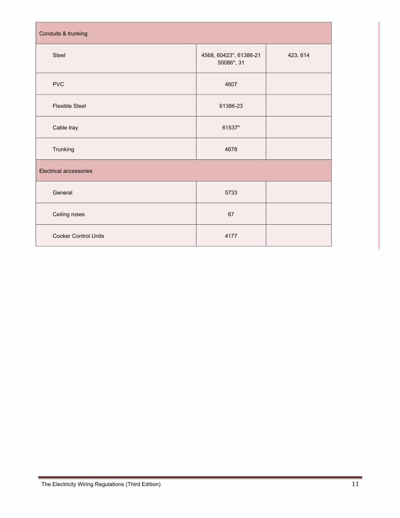
The Electricity Wiring Regulations (Third Edition) 11
Conduits & trunking
Steel 4568, 60423*, 61386-21 50086*, 31
423, 614
PVC 4607
Flexible Steel 61386-23
Cable tray 61537*
Trunking 4678
Electrical accessories
General 5733
Ceiling roses 67
Cooker Control Units 4177

The Electricity Wiring Regulations (Third Edition) 12
Components BS IEC
Accessories continued...
Household Appliances 60355*
Plugs & Socket-outlets (domestic) 546, 1363, 4573
Plugs & Socket-outlets (industrial) 60309*
Switches (domestic) 60669*
Lighting 60598*
Emergency lighting 5266
Signs and discharge lighting 559
Isolating (safety) transformers 61558*
LV switchgear & assemblies
General 61439* 439
Contactors & motor starters 60947* 947
Circuit-Breakers (MCB, MCCB) 60898* 898
Circuit-Breakers (RCD, RCBO) 1008*, 61008*, 61009* 755
Fuses 88, 60269*
Busbar trunking systems 61439-6 61439
General
Fire / combustibility test 60695*- 4
Degrees of protection & ingress 60529* 529

The Electricity Wiring Regulations (Third Edition) 13
Assemblies for construction Sites 4363 364-7-704
Hazardous areas 60079*
Lightning protection 62305*
Earthing 7430, 951, 4444,6701 364-5-54
Wiring diagram symbols 60617*
Identification and marking of the man-machine interface 60446*
RCD socket-outlets 7288
Solar PV system
Crystalline silicon terrestrial PV modules 61215*
61215
Solar PV modules safety qualification
61730
Solar PV inverters degree of protection 60529*
60529
Solar PV inverters protection class 60664-1*
62103, 60664-1
Solar PV inverters characteristics of the utility interface
61727
Solar PV inverters EMC Conformance
61000-6-1, 61000-6-2, 61000-6-3, 61000-6-4
Solar PV inverters Harmonics Conformance
61000-3-2, 61000-3-3, 61000-3-11, 61000-3-
12
Solar PV inverters power converting
equipment safety
62103, 62109
Solar PV d.c. cable See Note 4
See Note 4
Solar PV d.c. connectors 50521*
Solar PV array junction box and switchgear assemblies 61439-1*
61439-1
RCD Type B
62423
The Electricity Wiring Regulations (Third Edition) 14
A3. Continued...
Note: 1: British Standards marked with an asterix * are also issued as European Standards under the
same number (labelled as BS EN).
Note: 2: For compliance requirements under the Regulations see clause 3.1.2 and 3.1.4.
Note: 3: Reference standards for capacitors are given under Regulation 10.2
Note 4: For solar d.c. cables the following standards may be referenced UL 4703, TUV 2 PfG 1169/08.2007, VDE E PV 01:2008-02 and BS EN 50618 (when published).
British Standards are issued by the British Standards Institute (BSI), a UK National Standards body. The UK Wiring Regulations (BS 7671) are published jointly by BSI and the IET (formerly known as the IEE). The BSI represents UK international standards work through the British Electrotechnical Committee (BEC) which is a member of the International Electrotechnical Commission (IEC) and also a member of the European Committee for Electrotechnical Standardisation (CENELEC). There are 24 member countries of CENLEC (formed in 1973) whose role is to prepare standards for the European market. CENELEC issues ‘EN’ standards which are adopted by the member countries, and ‘HD’ standards which are adopted in their general technical content by member countries. The IEC (formed in 1906) has 48 member countries and IEC standards may be adopted voluntarily by any country.

The Electricity Wiring Regulations (Third Edition) 15
A4(a) Listofregulationsandclauseswhichdonotapplytoexistingelectricalinstallations
The Electricity Wiring Regulations are effective from 1 January 2008. For any Electrical Installations which were constructed prior to this date, the following Regulations do not apply.
Clause or Regulation Reason Application
Clause 3.1.4 Installation components to meet international standards
Does not apply (see also Clause 3.3.3 referring to repairs to existing installations)
Clause 3.5.6 Clause 5.3.4 Clause 5.3.5 Clause 5.5.1
Requirement for Earth Leakage Protection (ELP) and Earthed Equipotential Bonding (EEB)
Does not apply.
Clause 4.2.9 Emergency lighting in Electricity Intake rooms
Does not apply.
Clause 7.1.1 Prohibition of BS 546 plugs and socket-outlets in domestic premised
Does not apply but it is recommended to replace BS 546 socket-outlets with BS 1363 type
Clause 7.8.6 All Final Distribution Boards must, be arranged so as to provide for at least two zones of ELP.
Does not apply if a single RCD of residual operating current 30 mA is fitted to cover the whole DB, or a RCD of residual operating current of 100 mA is fitted to cover the whole DB and 30 mA RCBOs fitted in the DB for all bathrooms and socket-outlet circuits. Otherwise this Regulation shall apply after 1 January 2015, or the date of the next inspection or re-certification, whichever is the earlier.
[Note: for the avoidance of doubt, for any Electrical Installations constructed before 1 January 2008, Clause 7.8.6 (Regulation 7.8) shall apply after 1 January 2015, or the date of the next inspection or re-certification (which ever is the earlier), unless the conditions in the above table satisfied.]

The Electricity Wiring Regulations (Third Edition) 16
A4(b) RelevantextractsofLawNo(2)of1998
Relevant Extracts of Law No (2) of 1998 Concerning the Regulation of the Water, Wastewater and Electricity Sector
(as amended)
Article (54) - General Duties The Regulation and Supervision Bureau when performing its functions under this Law, shall have a duty to exercise its functions in a manner which best calculated to – (1) ensure the security of the supply of water and electricity and wastewater services in the Emirate; (2) ensure the connection and supply of water and electricity and connection to sewerage networks for
all customers; (3) ensure the provision of special health and safety regulations related to supply of water, wastewater
services and electricity to the general public; (6) have special regard to the interests of those persons whose lives may be endangered by the lack of
potable water, sewerage services or electricity and others with special needs in connection with the cost and method of supply of water and/or electricity, or through the use of appliances and fittings;
Article (55) - Functions of the Regulation and Supervision Bureau for the Water and Electricity Sector The powers of the Regulations and Supervision Bureau shall include- (3) the establishment, maintenance, review and amendment as appropriate of technical and
performance standards for the water and electricity sector and the monitoring and enforcement of compliance with such technical standards;
(4) the establishment, maintenance, review and monitoring of safety standards for the water, electricity
and sewerage services sector and monitoring and enforcing compliance with such safety standards; (9) making regulations and orders as provided elsewhere in this Law. Article (60) - Inspectors (1) The Regulation and Supervision Bureau may appoint qualified persons whose duties shall include
duties to – (c) inspect and test, where required, such plant and equipment at the consumer's premises;

The Electricity Wiring Regulations (Third Edition) 17
A4(b)Continued... Article (62) - Powers to make regulation The Regulation and Supervision Bureau may, in consultation with whom it sees fit, make such regulations as it sees fit for the purposes set out in Articles (63) and (68) of this Law¹. Article (63) - Supply regulations Regulations made pursuant to Article (62) of this Law may be made for the following purposes, namely to – (1) secure regular and efficient supply of water and electricity and provision of sewerage services; (2) protect the general public from danger related to water, electricity and sewerage works and
installations; (3) eliminate or reduce the risk of personal injury; (8) ensure that the water and electricity fittings installed and used by persons to whom water and
electricity are to be supplied are safe; and (9) promote the conservation of water and the efficient use of water and electricity. Article (65) - Contents of supply regulations - specific Regulations made under Article (62) of this Law may – (1) prohibit transmission or supply in specified circumstances; (2) require notification of accidents, failures of supply and/or transmission or distribution facilities and/or
when sewerage services are provided; (3) require plans, maps etc to be kept and made available for inspection and copying; (4) relieve the Abu Dhabi Water and Electricity Company and classes of licensed operators specified in
the regulations from obligations to supply water, electricity or sewerage services in specified circumstances;
(5) require compliance with notices served by the Regulation and Supervision Bureau which –
are intended to prevent or end a breach of regulations made under Chapter Three of Part Four of this Law; or eliminate/reduce risk of personal injury or property damage or interference with property;
(6) provide for deemed compliance with technical standards and requirements; (7) provide for exemptions from the requirements of regulations made under Chapter Three of Part
Four of this Law; (8) restrict or require the use of certain, products, substances or processes or forbid unapproved
substances, products and processes; ¹ Article 68 relates to Street Works and Access Regulations

The Electricity Wiring Regulations (Third Edition) 18
A4(b)Continued... (9) require substances, products and processes to comply with standards or other requirements
established by the regulations; (10) provide for certain persons/organisations to give approvals required by the regulations and for such
approvals to be subject to conditions or modification and revocation; (11) require the provision of information to prescribed persons; (13) forbid the use or installation of fittings which have not been approved; (14) require water, electricity and wastewater fittings to be of a prescribed size, nature, strength and
workmanship; (15) impose requirements as to installation, arrangement, connection, testing, disconnection, alteration
and repair; (16) impose requirements regarding earthing of electrical installations, electrical voltage and frequency;
and (17) enable the Regulation and Supervision Bureau to authorise any departures from the regulations as
may be required and to make those departures subject to conditions. Article (66) - Failure to comply with regulations Failure of any person to comply with regulations made under Article (62) of this Law shall be punished with a fine of not less than AED 250,000. In case the same failure is repeated by such person, the fine is doubled. Article (67) - Regulations disputes The court with the appropriate jurisdiction shall hear disputes relating to regulations made under Article (62) of this Law. Article (106) - Duty to enforce by final order Subject to Article (107) of this Law, where the Regulation and Supervision Bureau is satisfied that a licensed operator is contravening or is likely to contravene any condition of its licence, the Regulation and Supervision Bureau shall as soon as practicable by a final order make such provision as appears to the Regulation and Supervision Bureau to be requisite so as to secure compliance with that condition. Article (114) - Power to fine A final order may include a requirement on the licence holder to pay a fine of such amount, being not less than Dirhams 50,000, as the Regulation and Supervision Bureau determines to be appropriate.

The
A5
e Electricity W
(a)
iring Regulatio
Distribu
ons (Third Edi
tioncom
tion)
mpanyear
rthedsys
stem(TNN‐S)
19

The
A5
e Electricity W
(b)
iring Regulatio
Locallye
ons (Third Edi
eartheds
tion)
system(T
TT)
20

The
A5
e Electricity W
(c)
iring Regulatio
Distribusystem(
ons (Third Edi
tioncom(TN‐San
tion)
mpanyeardTT)
rthedsys
stemwithhlocallyearthed
21
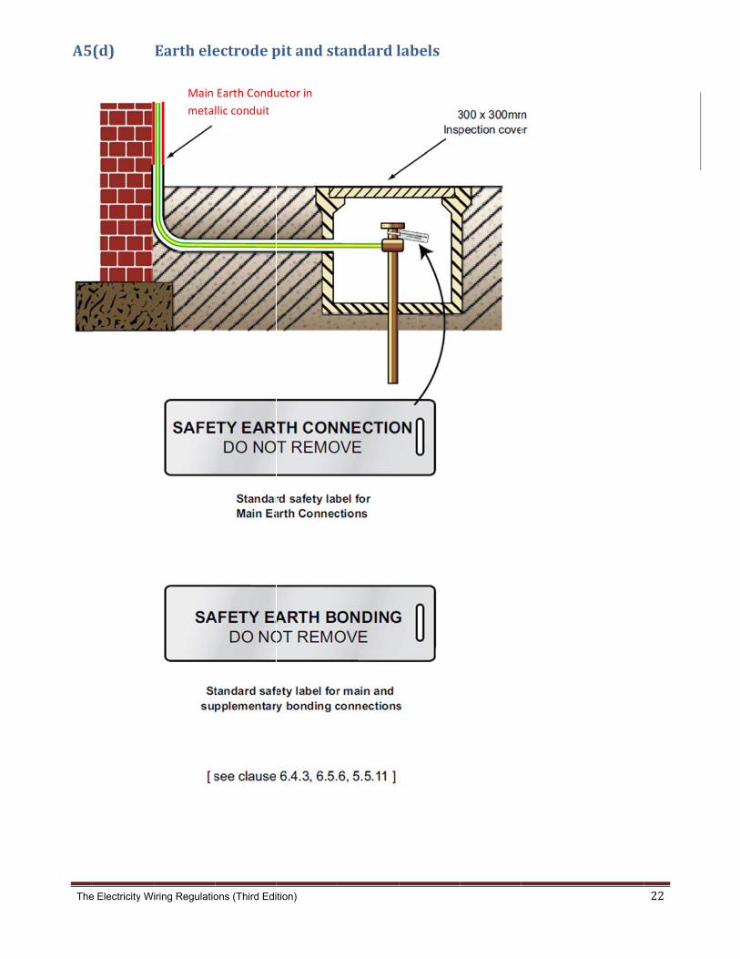
The
A5
e Electricity W
(d)
iring Regulatio
Earthele
Main
metal
ons (Third Edi
ectrodep
Earth Condu
llic conduit
tion)
pitandst
uctor in
tandardl
labels
22
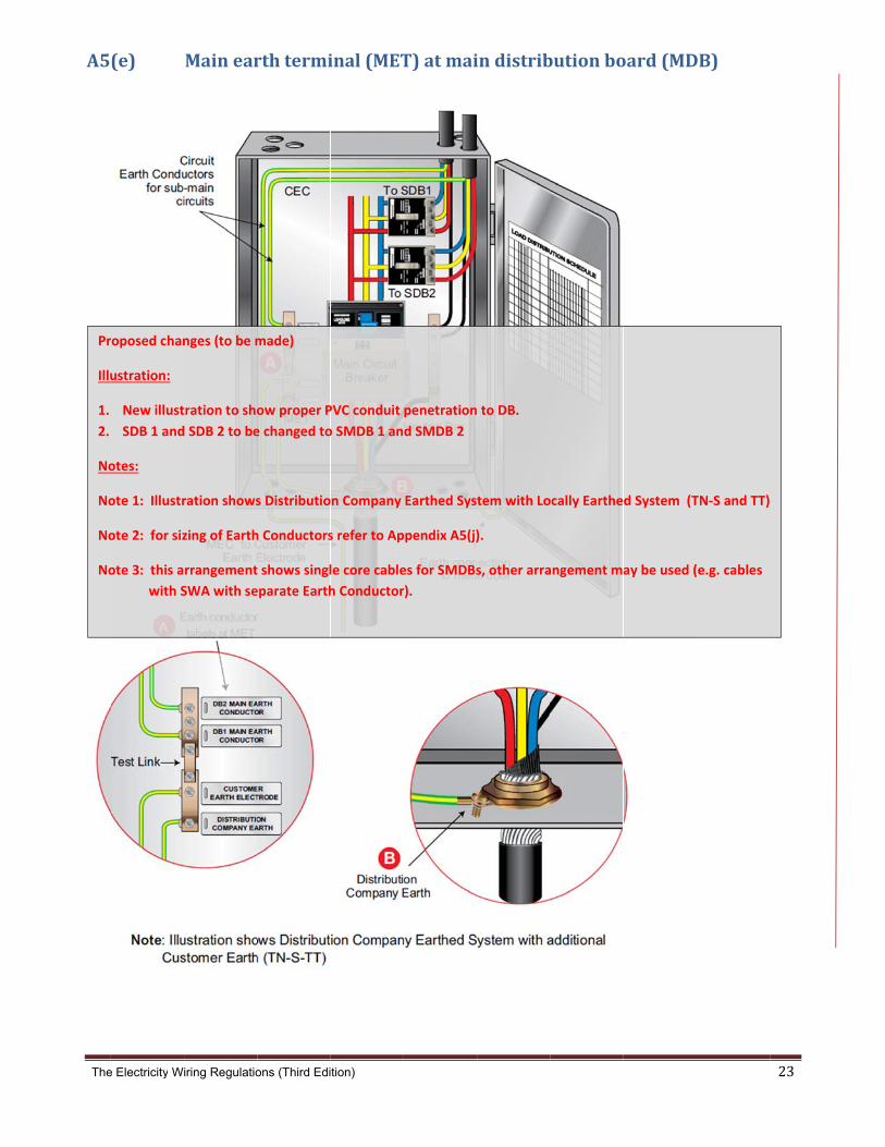
The
A5
Pr
Illu
1.
2.
No
No
No
No
e Electricity W
(e)
roposed chan
ustration:
New illust
SDB 1 and
otes:
ote 1: Illustr
ote 2: for siz
ote 3: this a
with S
iring Regulatio
Mainear
nges (to be m
tration to sho
d SDB 2 to be
ration shows
zing of Earth
rrangement
SWA with se
ons (Third Edi
rthtermi
made)
ow proper P
e changed to
s Distributio
h Conductors
t shows singl
eparate Earth
tion)
inal(MET
PVC conduit
o SMDB 1 an
n Company
s refer to Ap
le core cable
h Conductor
T)atmai
penetration
d SMDB 2
Earthed Sys
ppendix A5(j)
es for SMDBs
r).
indistrib
to DB.
tem with Lo
).
s, other arra
butionbo
ocally Earthe
angement m
oard(MD
d System (T
ay be used (
DB)
TN‐S and TT)
(e.g. cables
23
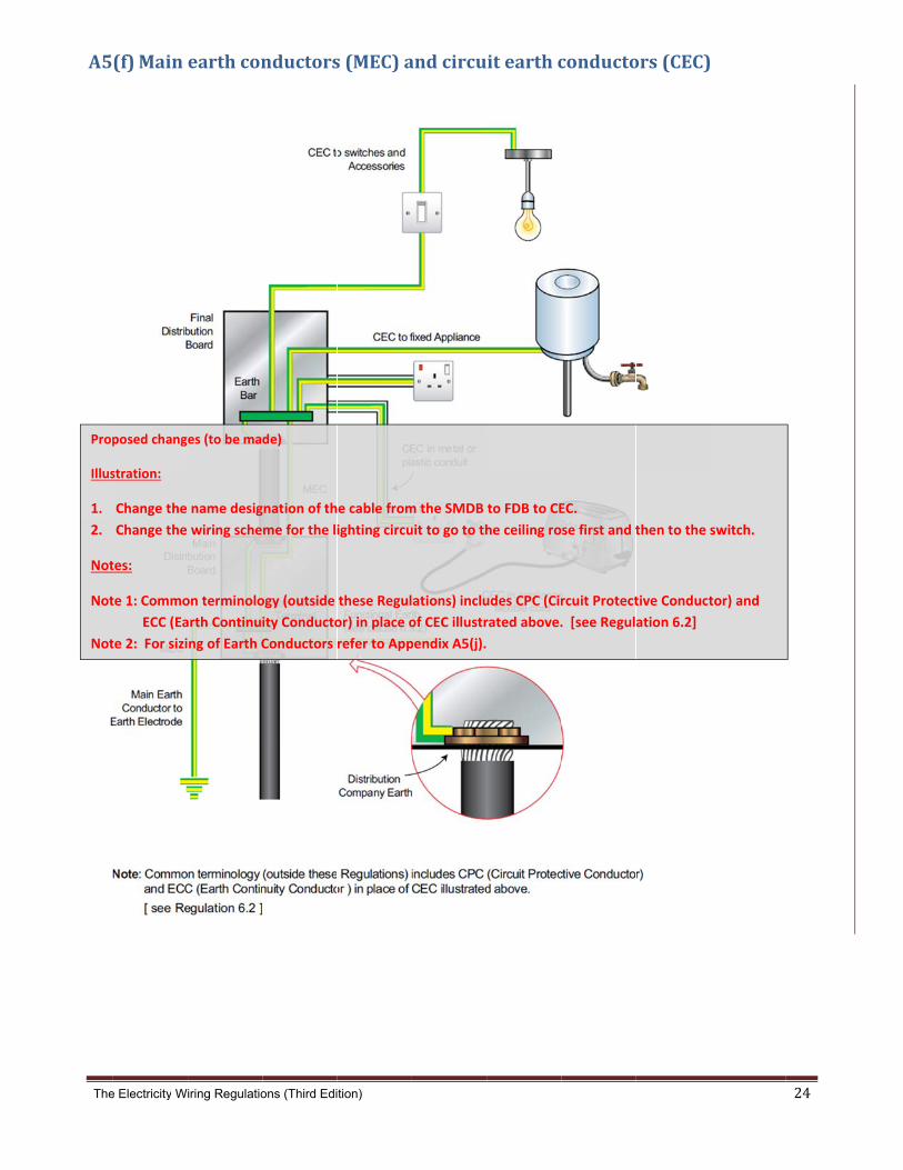
The
A5
Prop
Illus
1.
2.
Not
Not
Not
e Electricity W
(f)Main
posed chang
stration:
Change the
Change the
tes:
te 1: Commo
ECC (Ea
te 2: For sizi
iring Regulatio
earthcon
es (to be ma
name desig
wiring sche
on terminolo
arth Continui
ng of Earth C
ons (Third Edi
nductors
de)
gnation of th
me for the li
ogy (outside
ity Conducto
Conductors
tion)
s(MEC)a
e cable from
ighting circu
these Regul
or) in place o
refer to App
andcircu
m the SMDB
uit to go to th
ations) inclu
of CEC illustr
pendix A5(j).
itearthc
to FDB to CE
he ceiling ro
udes CPC (Cir
rated above.
conducto
EC.
se first and t
rcuit Protect
. [see Regul
ors(CEC)
then to the s
tive Conduct
ation 6.2]
switch.
tor) and
24
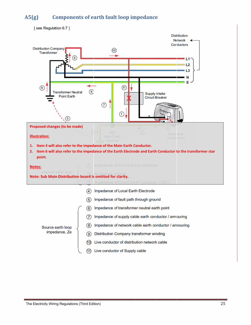
The
A5
P
Il
1
2
N
N
e Electricity W
(g)
Proposed cha
llustration:
1. Item 4 wi
2. Item 6 wi
point.
Notes:
Note: Sub Ma
iring Regulatio
Compon
anges (to be m
ill also refer t
ill also refer t
ain Distribut
ons (Third Edi
entsofe
made)
to the imped
to the imped
tion board is
tion)
arthfaul
ance of the M
ance of the E
s omitted for
ltloopim
Main Earth C
Earth Electro
r clarity.
mpedance
Conductor.
de and Earth
e
h Conductor tto the transfo
ormer star
25

The Electricity Wiring Regulations (Third Edition) 26
A5(h) EarthfaultloopimpedancevaluesrequiredforMCBs(at230V)
Device rating (A)
MCB type B
MCB type C
MCB type D
3 15.33 - -
6 7.67 3.83 1.92
10 4.60 2.30 1.15
16 2.87 1.44 0.72
20 2.30 1.15 0.57
25 1.84 0.92 0.46
32 1.44 0.72 0.36
40 1.15 0.57 0.29
50` 0.92 0.46 0.23
63 0.73 0.36 0.18
[from table 41.3 of BS 7671]
Note 1: The above values are given for conductor temperatures of 70˚C. As measurements are normally taken at room temperature the measured values must be approximately 20% less than tabulated above.
Note 2: The above values are used as an alternative to calculating the disconnection time for each specific situation. i.e. MCBs will operate in the instantaneous mode if the Earth Fault Loop Impedance value is kept below the above levels. For EFL Impedance values higher than shown above it is still possible to comply with the requirement of 0.4s disconnection for all Circuits in an Electrical Installation if a check is made against the manufacturer’s time-current performance chart.
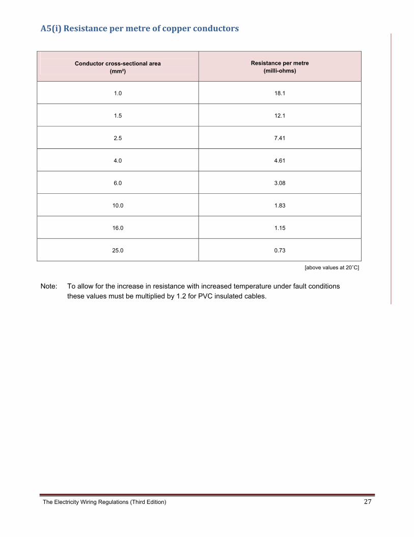
The Electricity Wiring Regulations (Third Edition) 27
A5(i)Resistancepermetreofcopperconductors
Conductor cross-sectional area
(mm²)
Resistance per metre (milli-ohms)
1.0 18.1
1.5 12.1
2.5 7.41
4.0 4.61
6.0 3.08
10.0 1.83
16.0 1.15
25.0 0.73
[above values at 20˚C]
Note: To allow for the increase in resistance with increased temperature under fault conditions
these values must be multiplied by 1.2 for PVC insulated cables.
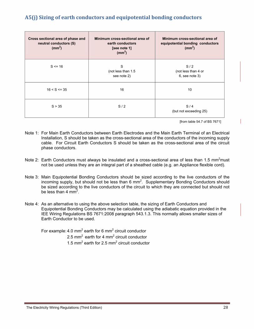
The Electricity Wiring Regulations (Third Edition) 28
A5(j)Sizingofearthconductorsandequipotentialbondingconductors
Cross sectional area of phase and neutral conductors (S)
(mm2)
Minimum cross-sectional area of earth conductors
[see note 1] (mm2)
Minimum cross-sectional area of equipotential bonding conductors
(mm2)
S <= 16 S (not less than 1.5
see note 2)
S / 2 (not less than 4 or
6, see note 3)
16 < S <= 35 16 10
S > 35 S / 2 S / 4 (but not exceeding 25)
[from table 54.7 of BS 7671]
Note 1: For Main Earth Conductors between Earth Electrodes and the Main Earth Terminal of an Electrical Installation, S should be taken as the cross-sectional area of the conductors of the incoming supply cable. For Circuit Earth Conductors S should be taken as the cross-sectional area of the circuit phase conductors.
Note 2: Earth Conductors must always be insulated and a cross-sectional area of less than 1.5 mm2must not be used unless they are an integral part of a sheathed cable (e.g. an Appliance flexible cord).
Note 3: Main Equipotential Bonding Conductors should be sized according to the live conductors of the incoming supply, but should not be less than 6 mm2. Supplementary Bonding Conductors should be sized according to the live conductors of the circuit to which they are connected but should not be less than 4 mm2.
Note 4: As an alternative to using the above selection table, the sizing of Earth Conductors and Equipotential Bonding Conductors may be calculated using the adiabatic equation provided in the IEE Wiring Regulations BS 7671:2008 paragraph 543.1.3. This normally allows smaller sizes of Earth Conductor to be used.
For example: 4.0 mm2 earth for 6 mm2 circuit conductor
2.5 mm2 earth for 4 mm2 circuit conductor
1.5 mm2 earth for 2.5 mm2 circuit conductor

The Electricity Wiring Regulations (Third Edition) 29
A5(k) Minimumnumberofearthelectrodes The number of Earth Electrodes required at a Premises will be determined primarily by the value of Earth Resistance that can be achieved from each. However, the minimum number in any case shall be as shown below:
Main incoming circuit-breaker rating (Amps)
Minimum number of earth electrodes
Minimum size of main earth conductor (mm2)
60/100 1 16
200 1 50
300 1 50
400 1 70
500 2 70
600 2 70
800 2 70
1000 2 70
1600 2 70
2000 2 150
2500 2 150
Note 1: Standard earth electrode diameters are 9 mm, 12.5 mm or 15 mm for copper-clad steel, or 16 mm for stainless steel. Standard lengths are 1.2 m or 1.5 m (see also BS 7430).
Note 2: Structural foundations of large buildings may be used as Earth Electrodes, see clause 6.4.8 and 6.8.4.
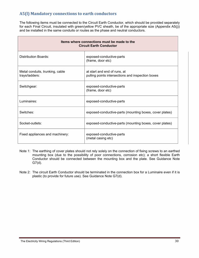
The Electricity Wiring Regulations (Third Edition) 30
A5(l)Mandatoryconnectionstoearthconductors The following items must be connected to the Circuit Earth Conductor, which should be provided separately for each Final Circuit, insulated with green/yellow PVC sheath, be of the appropriate size (Appendix A5(j)) and be installed in the same conduits or routes as the phase and neutral conductors.
Items where connections must be made to the Circuit Earth Conductor
Distribution Boards: exposed-conductive-parts (frame, door etc)
Metal conduits, trunking, cable trays/ladders:
at start and end of runs, at pulling points intersections and inspection boxes
Switchgear: exposed-conductive-parts (frame, door etc)
Luminaires: exposed-conductive-parts
Switches: exposed-conductive-parts (mounting boxes, cover plates)
Socket-outlets: exposed-conductive-parts (mounting boxes, cover plates)
Fixed appliances and machinery: exposed-conductive-parts (metal casing etc)
Note 1: The earthing of cover plates should not rely solely on the connection of fixing screws to an earthed mounting box (due to the possibility of poor connections, corrosion etc); a short flexible Earth Conductor should be connected between the mounting box and the plate. See Guidance Note G7(d).
Note 2: The circuit Earth Conductor should be terminated in the connection box for a Luminaire even if it is plastic (to provide for future use). See Guidance Note G7(d).

The Electricity Wiring Regulations (Third Edition) 31
A5(m) ResidualoperatingcurrentsettingsforRCDsandELPdevices
Equipment Maximum Residual operating current settings (mA)
13 A switched-socket outlets 30
Water heaters 30
Kitchen fixed Appliances (e.g. washing machine)
30
Domestic water pumps 30
Swimming pool pumps, or jacuzzi 30
Underwater lighting SELV only
General fixed lighting (except in bathrooms and swimming pools)
100
Floodlighting 100 - 300
Window or split type air conditioning 100
Air handling, a/c fan coils etc 100
Central or package a/c units 100 - 300
Irrigation pump 100
Electric Cooker 30
Industrial machines etc 100 - 300
Elevators, escalators, lifts 300 - 500
Neon signs 300
School areas (e.g. laboratory for children) 10
LV main circuit breakers or switchboards (Electricity Intake) See Note 4
Note 1: where two values are indicated the higher value is allowed only where the equipment is not normally accessible to any person.
Note 2: all Final Circuits in a bathroom (including lighting, but excluding FCUs in a ceiling void) must be provided with 30 mA RCD protection. See clause 9.3.2(a).

The Electricity Wiring Regulations (Third Edition) 32
A5(m) Continued...
Note 3: where a circuit supplies more than one type of equipment the lower value must be used for RCD protection (e.g. a circuit supplying bedroom lighting and bathroom lighting must be protected by a 30 mA RCD).
Note 4: the selection of ELP devices at main switchboards must take into account the requirement for discrimination with downstream protective devices (clause 5.4.5 and 5.4.6). For small supplies (200A or less) a 300mA RCD device may be used, with time delay of 200ms. For larger supplies (above 200A) earth leakage protection relays may be used in conjunction with MCCBs or ACBs incorporating a trip unit (e.g. 1A, 3A, 5A with time delay up to 400ms). Irrespective of the earth leakage protection provided at the main switchboard, the incomer MCCB or ACB shall have short-circuit protection to ensure tripping within 400ms taking into account the Earth Fault Loop Impedance.
The table opposite shows the required residual operating current values for RCDs and other Earth Leakage Protection devices. These are intended to provide supplementary protection of electric shock as well as protection against high resistance earth faults which may not operate overcurrent devices and pose a risk of overheating or fire, see Regulation 5.4. All Final Circuits where Appliances may be used by any person must be provided with Earth Leakage Protection (clause 5.3.5). Earth Leakage Protection must also be provided at the main Electricity Intake and subsequent distribution boards where necessary, see Regulation 5.4.

The
A6
e Electricity W
(a)
iring Regulatio
Time‐cu
ons (Third Edi
rrentcha
tion)
aracteris
sticofMC
CBsasmuultipleoffratedcu
urrent
33

The
A6
e Electricity W
(b)
Propo
Illustr
1. U
2. C
iring Regulatio
Time‐cu
osed changes
ration:
Update figure
Correct time s
ons (Third Edi
rrentcha
s (to be made
e to latest edi
scale to start
tion)
aracteris
e)
ition of BS 76
at 0.01 seco
sticofTyp
671 (fig 3A4)
onds
peBMCBBs
34

The
A6
e Electricity W
(c)Time‐
Pro
Illu
1.
2.
iring Regulatio
‐current
oposed chang
ustration:
Update figu
Correct tim
ons (Third Edi
characte
ges (to be ma
ure to latest
me scale to st
tion)
eristicof
ade)
edition of BS
art at 0.01 se
TypeCM
S 7671 (fig 3A
econds
MCBs
A5)
35

The
A6
e Electricity W
(d)
Propo
Illustra
1. Up
2. Co
iring Regulatio
Time‐cu
sed changes
ation:
pdate figure
orrect time sc
ons (Third Edi
rrentcha
(to be made
to latest edit
cale to start a
tion)
aracteris
e)
tion of BS 76
at 0.01 secon
sticofTyp
71 (fig 3A6)
nds
peDMCBBs
36
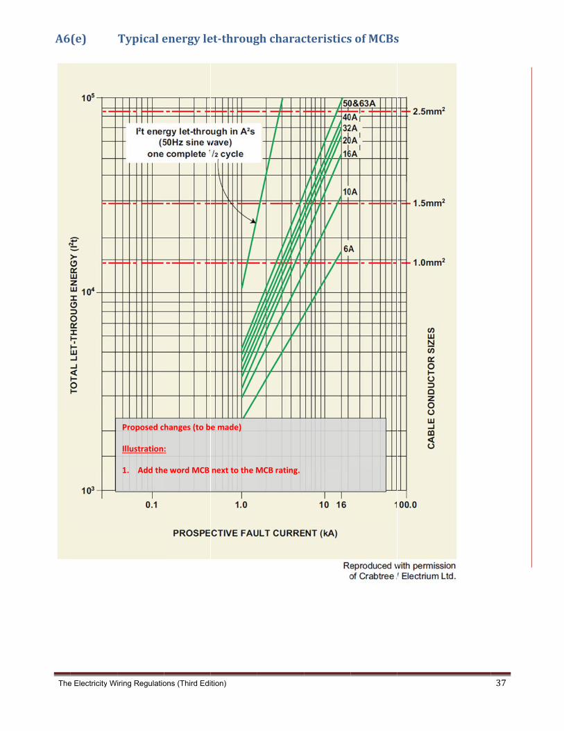
The
A6
e Electricity W
(e)
iring Regulatio
Typicale
Proposed c
Illustration
1. Add the
ons (Third Edi
energyle
hanges (to b
:
e word MCB
tion)
et‐throug
e made)
next to the M
ghcharac
MCB rating.
cteristicssofMCBss
37

The Electricity Wiring Regulations (Third Edition) 38
A6(f)MCBsselectioncriteria
Operating characteristics of MCB types and the required earth fault loop impedance values are given in Appendix A6(a) to A6(d) and Appendix A5(h). MCBs for common cable sizes and Circuits are shown in the following table:
MCB nominal rating Amps
Cable size mm2
Cable rating at 30˚C, PVC
Amps, (kW)
Cable rating at 40˚C, PVCAmps, (kW)
Typical circuit application
6 1.5 17.5 (3.4)
15.2 (3.0)
Lighting (light load)
10 2.5 24.0 (4.7)
20.9 (4.1)
Lighting (heavy load)
16 2.5 24.0 (4.7)
20.9 (4.1)
Radial Circuit to socket-outlets
20 4.0 32.0 (6.3)
27.8 (5.4)
Radial Circuit to fixed appliance
32 2 x 4.0 48 (9.3)
41.7 (8.1)
Ring Circuit to socket-outlets
32 6.0 41.0 (8.0)
35.7 (7.0)
Radial Circuit to large Appliance (e.g. cooker)
40 10.0 57.0 (11.1)
49.6 (9.7)
Radial Circuit to machinery (e.g. chiller unit)
Note 1: cable ratings are taken from Appendix A7(a), assuming one circuit in conduit, with temperature correction factors applied from
Appendix A7(g). Power factor of 0.85 is assumed to calculate kW ratings at 230V.
Note 2: selection of MCBs for overload protection of cables must take account of the device characteristics given in Appendix A6(b) to
A6(d). These are based on minimum MCB operating currents of 1.45 times the MCB nominal rating (In) and a maximum 'non-
tripping' current of 1.15 times In. Hence, cables must be selected with ratings at least 1.15 times the MCB nominal rating (see
IEE Guidance Note 6 - section 2).

The Electricity Wiring Regulations (Third Edition) 39
A6(f)Continued... The classification of Types B, C or D is based on the fault current rating at which magnetic operation occurs and their ability to handle surge currents without tripping. See Appendix A6(a).
• Type B devices are designed to trip at fault currents of 3-5 times rated current (In). For example a 10 A device will trip at 30-50 A
• Type C devices are designed to trip at 5-10 times In • Type D devices are designed to trip at 10-20 times In Type B devices are generally suitable for domestic applications. Type C devices are the normal choice for commercial and industrial applications where large groups of fluorescent lighting, motors, etc are used. Type D devices have more limited applications, where high inrush currents may be expected. For example, large battery systems, motors, transformers, etc. Sometimes failure of tungsten filament lamps can trip Type B circuit-breakers in domestic and retail environments. This is caused by high arcing currents occurring at the time of failure and is generally associated with inferior quality lamps. A Type C device may be substituted for a Type B device where unwanted tripping persists, especially in commercial applications. A change from Type C to Type D devices should only be taken after careful consideration of the installation conditions, in particular the operating times required by Regulation 5.5.
(Referenced from www.voltimum.co.uk)

The
A6
e Electricity W
(g)
iring Regulatio
Internal
ons (Third Edi
lconstru
tion)
uctionofM
MCB
40

The Electricity Wiring Regulations (Third Edition) 41
A7(a) CircuitratingandvoltagedropforPVCsinglecorecables(non‐armoured)
Standard cable ratings and Voltage drop for single core, PVC (70˚C thermoplastic), non-armoured, stranded copper conductor (BS 6004), with or without sheath, installed in buried or surface conduit or trunking.
Cross sectional
area (mm²)
In conduit in thermal insulation
(A)
In conduit on wall or in concrete (A)
Voltage drop (mV/A/m)
2 cables single phase a.c. or d.c.
3 or 4 cables three phase
a.c.
2 cables single phase a.c. or
d.c.
3 or 4 cables three phase a.c.
2 cables single phase a.c. or
d.c.
3 or 4 cables three phase a.c.
1.0 11 10.5 13.5 12 44 38
1.5 14.5 13.5 17.5 15.5 29 25
2.5 20 18 24 21 18 15
4.0 26 24 32 28 11 9.5
6.0 34 31 41 36 7.3 6.4
10 46 42 57 50 4.4 3.8
16 61 56 76 68 2.8 2.4
25 80 73 101 89 - -
35 99 89 125 110 - -
50 119 108 151 134 - -
70 151 136 192 171 - -
At 30˚C ambient temperature [see Appendix A7(g) for grouping factors]
Note 1: Data from table 4D1A and 4D1B of BS 7671.
Note 2: For voltage drop for cables above 25 mm2 refer to BS 7671.

The Electricity Wiring Regulations (Third Edition) 42
A7(b) CircuitratingandvoltagedropforPVCmulti‐corecables(non‐armoured)
Standard cable ratings and voltage drop for PVC (70˚C thermoplastic) multi-core cables (sheathed), non-armoured, stranded copper conductor (BS 6004), installed in buried or surface mounted conduit or trunking, or on exposed, perforated cable tray.
Cross sectional
area (mm²)
In conduit on wall or in concrete (A)
Clipped direct to a wall (A)
On perforated cable tray or in free air (A)
2 core single phase a.c. or
d.c.
3 or 4 core three phase a.c.
2 core single phase a.c. or
d.c.
3 or 4 core three phase a.c.
2 core single phase a.c. or
d.c.
3 or 4 core three phase
a.c.
1.0 13 11.5 15 13.5 17 14.5
1.5 16.5 15 19.5 17.5 22 18.5
2.5 23 20 27 24 30 25
4 30 27 36 32 40 34
6 38 34 46 41 51 43
10 52 46 63 57 70 60
16 69 62 85 76 94 80
25 90 80 112 96 119 101
35 111 99 138 119 148 126
50 133 118 168 144 180 153
70 168 149 213 184 232 196
95 201 179 258 223 282 238
120 232 206 299 259 328 276
150 258 225 344 299 379 319
At 30˚C ambient temperature [see Appendix A7(g) for grouping factors]
Note 1: Data taken from table 4D2A and 4D2B of BS 7671.
Note 2: 2-core refers to single-phase circuits, 3 or 4-core refers to three-phase circuits.

The Electricity Wiring Regulations (Third Edition) 43
A7(b) Continued...
Cable size (mm²)
Voltage drop (mV/A/m)
1.0 1.5 2.5 4 6 10 16
2 core single phase a.c. or d.c.
44 29 18 11 7.3 4.4 2.8
3 or 4 core three phase a.c.
38 25 15 9.5 6.4 3.8 2.4
Note 1: For voltage drop for cables above 16 mm² refer to BS 7671.

The Electricity Wiring Regulations (Third Edition) 44
A7(c) CircuitratingandvoltagedropforPVCmulti‐corecables(armoured)Standard cable ratings and Voltage drop for multi-core armoured, PVC (70˚C thermoplastic) cables, stranded copper conductor (BS 5467), installed exposed (clipped to a wall) or on perforated cable tray.
Cross sectional
area (mm²)
Clipped direct to a wall
(A)
On perforated cable tray
(A)
Voltage drop (mV/A/m)
2 core single phase a.c. or
d.c.
3 or 4 core three phase
a.c.
2 core single phase a.c. or
d.c.
3 or 4 core three phase a.c.
2 core single phase a.c. or d.c.
3 or 4 core three phase a.c.
1.5 21 18 22 19 29 25
2.5 28 25 31 26 18 15
4 38 33 41 35 11 9.5
6 49 42 53 45 7.3 6.4
10 67 58 72 62 4.4 3.8
16 89 77 97 83 2.8 2.4
25 118 102 128 110 - -
35 145 125 157 135 - -
50 175 151 190 163 - -
70 222 192 241 207 - -
95 269 231 291 251 - -
120 310 267 336 290 - -
150 356 306 386 332 - -
185 405 348 439 378 - -
240 476 409 516 445 - -
300 547 469 592 510 - -
At 30˚C ambient temperature [see Appendix A7(g) for grouping factors]
Note 1: Data taken from table 4D4A and 4D4B of BS 7671.
Note 2: 2 core refers to single-phase circuits, 3 or 4 core refers to three-phase circuits.
Note 3: For voltage drop for cables above 16 mm² refer to BS 7671.

The Electricity Wiring Regulations (Third Edition) 45
A7(d) Circuitratingandvoltagedropforthermo‐setting(XLPE)multi‐corecables(armoured)
Standard cable ratings and voltage drop for multi-core, 90˚C thermosetting plastic insulated (XLPE), armoured cable, stranded copper conductor (BS 5467 and BS 6724), surface mounted or on cable tray
Cross sectional
area (mm²)
Clipped direct to a wall
(A)
On perforated cable tray
(A)
Voltage drop (mV/A/m)
2 core single phase a.c. or
d.c.
3 or 4 core three phase
a.c.
2 core single phase a.c. or
d.c.
3 or 4 core three phase a.c.
2 core single phase a.c. or
d.c.
3 or 4 core three phase a.c.
1.5 27 23 29 25 31 27
2.5 36 31 39 33 19 16
4 49 42 52 44 12 10
6 62 53 66 56 7.9 6.8
10 85 73 90 78 4.7 4.0
16 110 94 115 99 2.9 2.5
25 146 124 152 131 - -
35 180 154 188 162 - -
50 219 187 228 197 - -
70 279 238 291 251 - -
95 338 289 354 304 - -
120 392 335 410 353 - -
150 451 386 472 406 - -
185 515 441 539 463 - -
240 607 520 636 546 - -
300 698 599 732 628 - -
At 30˚C ambient temperature [see Appendix A7(g) for grouping factors]
Note 1: From table 4E4A and 4E4B of BS 7671
[2 core refers to single-phase circuits, 3 or 4 core refers to three-phase circuits].
Note 2: For voltage drop for cables above 16 mm² refer to BS 7671.
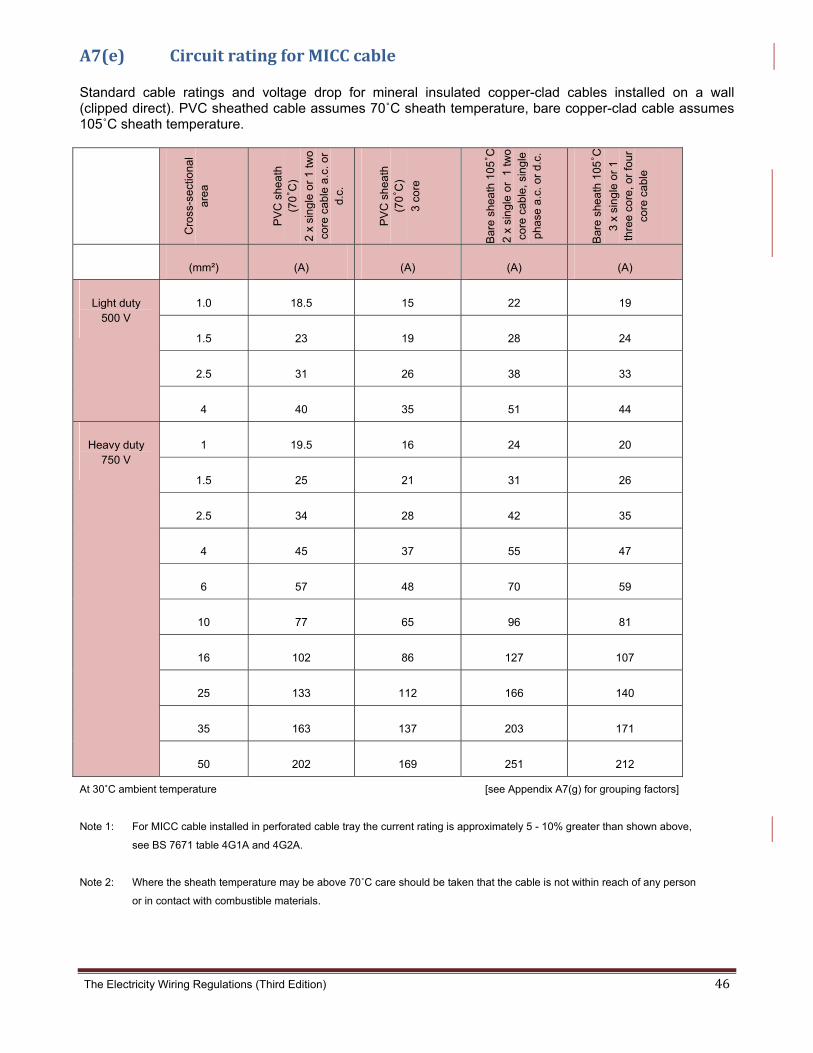
The Electricity Wiring Regulations (Third Edition) 46
A7(e) CircuitratingforMICCcable Standard cable ratings and voltage drop for mineral insulated copper-clad cables installed on a wall (clipped direct). PVC sheathed cable assumes 70˚C sheath temperature, bare copper-clad cable assumes 105˚C sheath temperature.
Cro
ss-s
ect
iona
l ar
ea
PV
C s
he
ath
(7
0˚C
)
2 x
sin
gle
or
1 tw
o
core
cab
le a
.c. o
r d
.c.
PV
C s
he
ath
(7
0˚C
)
3 co
re
Ba
re s
hea
th 1
05˚C
2 x
sin
gle
or
1 tw
o
core
cab
le, s
ing
le
pha
se a
.c. o
r d.
c.
Ba
re s
hea
th 1
05˚C
3 x
sin
gle
or
1
thre
e c
ore
, or
fou
r co
re c
able
(mm²) (A) (A) (A) (A)
Light duty 500 V
1.0 18.5 15 22 19
1.5 23 19 28 24
2.5 31 26 38 33
4 40 35 51 44
Heavy duty 750 V
1 19.5 16 24 20
1.5 25 21 31 26
2.5 34 28 42 35
4 45 37 55 47
6 57 48 70 59
10 77 65 96 81
16 102 86 127 107
25 133 112 166 140
35 163 137 203 171
50 202 169 251 212
At 30˚C ambient temperature [see Appendix A7(g) for grouping factors]
Note 1: For MICC cable installed in perforated cable tray the current rating is approximately 5 - 10% greater than shown above,
see BS 7671 table 4G1A and 4G2A.
Note 2: Where the sheath temperature may be above 70˚C care should be taken that the cable is not within reach of any person
or in contact with combustible materials.

The Electricity Wiring Regulations (Third Edition) 47
A7(f) Circuitratingandvoltagedropforflexiblecords Standard current ratings and voltage drop for flexible cords, 60˚C conductor temperature (PVC or rubber insulated), stranded copper conductors to BS 6500 (domestic applications).
Cross sectional area
Single phase Three phase Voltage drop (single-phase)
Voltage drop (three-phase)
Mass supportable by twin flexible
cord
(mm²) (A) (A) (mV/A/m) (mV/A/m) (kg)
0.5 3 3 93 80 2
0.75 6 6 62 54 3
1.0 10 10 46 40 5
1.25 13 - 37 - 5
1.5 16 16 32 27 5
2.5 25 20 19 16 5
4.0 32 25 12 10 5
At 30˚C ambient temperature [from table 4F3A and 4F3B of BS 7671]
For Ambient temperatures above 30˚C the following correction factors may be applied for flexible cords:
Ambient temperature (°C) 35 40 45 50 55
Correction factor 0.91 0.82 0.71 0.58 0.41
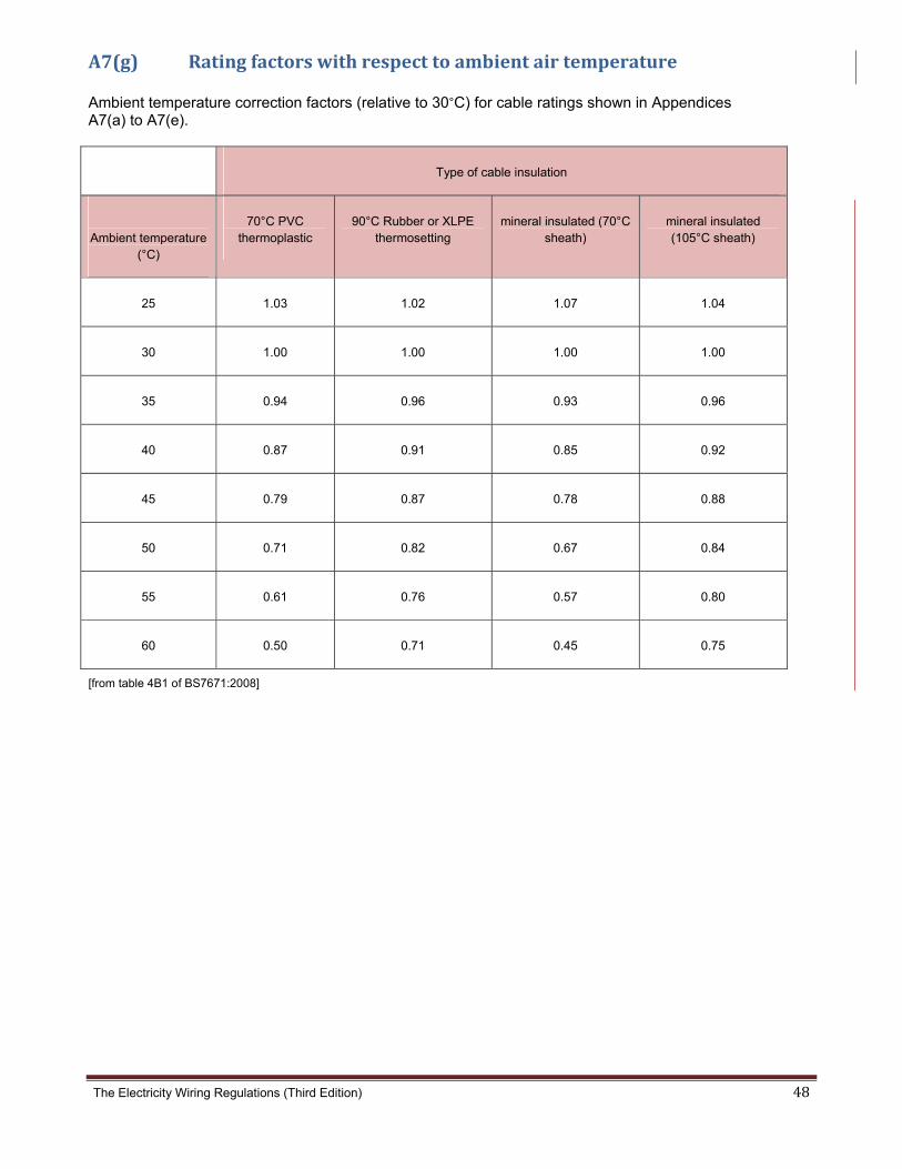
The Electricity Wiring Regulations (Third Edition) 48
A7(g) Ratingfactorswithrespecttoambientairtemperature Ambient temperature correction factors (relative to 30°C) for cable ratings shown in Appendices A7(a) to A7(e).
Type of cable insulation
Ambient temperature
(°C)
70°C PVC thermoplastic
90°C Rubber or XLPE thermosetting
mineral insulated (70°C sheath)
mineral insulated (105°C sheath)
25 1.03 1.02 1.07 1.04
30 1.00 1.00 1.00 1.00
35 0.94 0.96 0.93 0.96
40 0.87 0.91 0.85 0.92
45 0.79 0.87 0.78 0.88
50 0.71 0.82 0.67 0.84
55 0.61 0.76 0.57 0.80
60 0.50 0.71 0.45 0.75
[from table 4B1 of BS7671:2008]

The Electricity Wiring Regulations (Third Edition) 49
A7(h) Ratingfactorswithrespecttogroupingofcables Because of mutual heating effects the following correction factors should be applied to the tables in Appendix A7(a) to A7(e) for situations where a number of cables are installed close together. These factors assume all cables are fully loaded; however, if an individual cable is loaded below 30% of its rating it may be excluded from the total number in the group.
Method of installation
Number of cables
Enclosed in conduit (surface or buried) or bunched on a non-
metallic surface
Single layer, clipped to a non-metallic surface (wall or
floor)
Single layer multi-core on a
perforated cable tray
Single layer single-core on
a cable tray (touching)
2 0.80 0.85 0.88 0.87
3 0.70 0.79 0.82 0.82
4 0.65 0.75 0.77 0.80
5 0.60 0.73 0.75 0.80
6 0.57 0.72 0.73 0.79
7 0.54 0.72 0.73 0.79
8 0.52 0.71 0.72 0.78
9 0.50 0.70 0.72 0.78
12 0.45 0.70 0.72 0.78
16 0.41 0.70 0.72 0.78
20 0.38 0.70 0.72 0.78
[taken from table 4C1 of BS 7671]
Note 1: These factors are applicable to uniform groups of cable, equally loaded.
Note 2: Where horizontal clearances between adjacent cables exceed twice their overall diameter, no rating factor need to be applied.
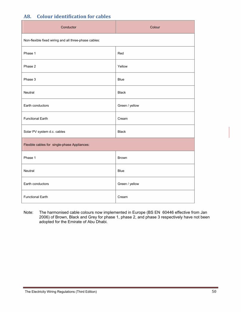
The Electricity Wiring Regulations (Third Edition) 50
A8. Colouridentificationforcables
Conductor Colour
Non-flexible fixed wiring and all three-phase cables:
Phase 1 Red
Phase 2 Yellow
Phase 3 Blue
Neutral Black
Earth conductors Green / yellow
Functional Earth Cream
Solar PV system d.c. cables Black
Flexible cables for single-phase Appliances:
Phase 1 Brown
Neutral Blue
Earth conductors Green / yellow
Functional Earth Cream
Note: The harmonised cable colours now implemented in Europe (BS EN 60446 effective from Jan 2006) of Brown, Black and Grey for phase 1, phase 2, and phase 3 respectively have not been adopted for the Emirate of Abu Dhabi.

The Electricity Wiring Regulations (Third Edition) 51
A9. Capacityofconduitsandtrunking
Conductor ( mm2 )
Diameter of Conduit (mm)
20 25 32
Maximum number of conductors
1.5 7 12 -
2.5 5 9 12
4.0 3 6 9
6.0 - 5 8
10.0 - 3 6
16.0 - - 4
25.0 - - 3
Note: For cable trays and trunking the space factor (total cross-sectional area of cables compared
with the interior cross-sectional area of trunking) must not exceed 50%.
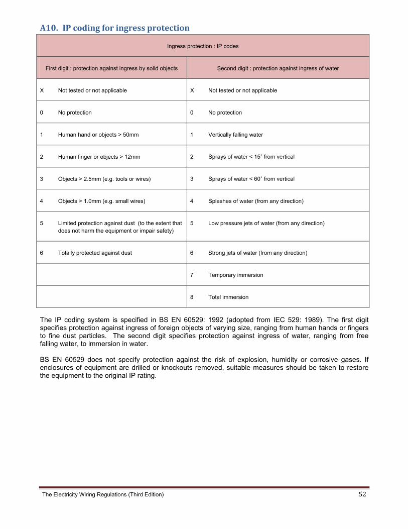
The Electricity Wiring Regulations (Third Edition) 52
A10.IPcodingforingressprotection
Ingress protection : IP codes
First digit : protection against ingress by solid objects Second digit : protection against ingress of water
X Not tested or not applicable X Not tested or not applicable
0 No protection 0 No protection
1 Human hand or objects > 50mm 1 Vertically falling water
2 Human finger or objects > 12mm 2 Sprays of water < 15˚ from vertical
3 Objects > 2.5mm (e.g. tools or wires) 3 Sprays of water < 60˚ from vertical
4 Objects > 1.0mm (e.g. small wires) 4 Splashes of water (from any direction)
5 Limited protection against dust (to the extent that does not harm the equipment or impair safety)
5 Low pressure jets of water (from any direction)
6 Totally protected against dust 6 Strong jets of water (from any direction)
7 Temporary immersion
8 Total immersion
The IP coding system is specified in BS EN 60529: 1992 (adopted from IEC 529: 1989). The first digit specifies protection against ingress of foreign objects of varying size, ranging from human hands or fingers to fine dust particles. The second digit specifies protection against ingress of water, ranging from free falling water, to immersion in water. BS EN 60529 does not specify protection against the risk of explosion, humidity or corrosive gases. If enclosures of equipment are drilled or knockouts removed, suitable measures should be taken to restore the equipment to the original IP rating.

The
A1
e Electricity W
1. Stand
iring Regulatio
dardwirin
Pr
1.
ons (Third Edi
ngdiagra
roposed ch
Symbols
a) Fused
b) 16A i
tion)
amsymb
hanges (to
s of the fo
d connecti
ndustrial s
bols
o be made
llowing w
ion unit
sockets
e)
will be add
ded
53

The
A1
e Electricity W
1. Conti
iring Regulatio
inued...
ons (Third Edition) 54

The
A1
This e
inspe
cond
Elect
Date
D
S
S
e Electricity W
2(a)
I
electrical ins
ected and tes
ition obtaine
ricity Wiring
of last inspe
Owne
Do not opera
In case
___
See clauses 3
See Appendix
Pr
1.
iring Regulatio
Labellin
mporta
Owner Not
stallation sho
sted, and a r
ed, as prescr
g Regulations
ection:
d and Ope
XYZ Compa
ate without
e of emerg
________
3.6.1, 3.6.7 a
x A19(f)
roposed ch
Introduc
various l
ons (Third Edi
ngofelec
ant
tice
ould be peri
report on its
ribed in the
s.
erated by
any
prior permis
gency call
______
nd 9.9.21
hanges (to
ce a numb
location in
tion)
tricalins
odically
s
y
ssion
:
o be made
ber of stan
n the Elec
stallation
تردد
ستمر
“Da
ھربائي
e)
ndard labe
ctrical Inst
n
PV
ئيسي للتيار المت
PV
ئيسي للتيار المس
nger solar
live
شحون بتيار كھھار".
See Re
els to be u
tallation.
V a.c. Side S
مفتاح العزل الرئ
V d.c. Side S
مفتاح العزل الرئ
PV cables
during day
مش –الشمسية في ضوء النھ
egulations 9.1
used for
Switch Discon
م –قة الشمسية
Switch Discon
م –قة الشمسية
s – d.c. Volt
ylight.
نظام الطاقة ا – مستمر
10
nnector
نظام الطاق
nnector
نظام الطاق
tage -
–"خطر
55
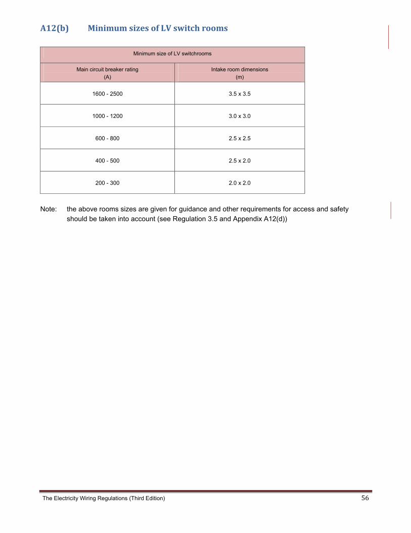
The Electricity Wiring Regulations (Third Edition) 56
A12(b) MinimumsizesofLVswitchrooms
Minimum size of LV switchrooms
Main circuit breaker rating
(A)
Intake room dimensions
(m)
1600 - 2500 3.5 x 3.5
1000 - 1200 3.0 x 3.0
600 - 800 2.5 x 2.5
400 - 500 2.5 x 2.0
200 - 300 2.0 x 2.0
Note: the above rooms sizes are given for guidance and other requirements for access and safety
should be taken into account (see Regulation 3.5 and Appendix A12(d))
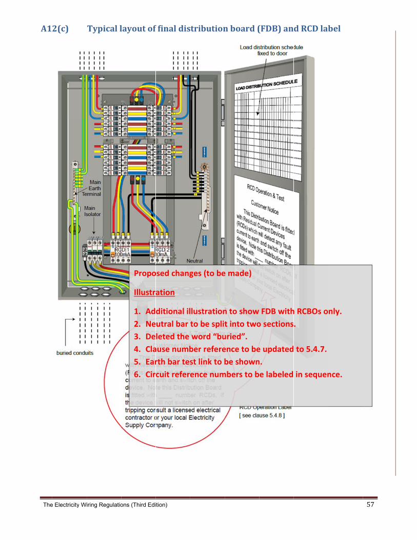
The
A1
e Electricity W
2(c)
iring Regulatio
Typicall
ons (Third Edi
layoutof
Propo
Illustr
1. Ad
2. Ne
3. De
4. Cla
5. Ear
6. Cir
tion)
f finaldis
osed chang
ation
ditional il
utral bar
leted the
ause numb
rth bar tes
cuit refere
stribution
ges (to be
llustration
to be split
word “bu
ber refere
st link to b
ence num
nboard(
e made)
n to show
t into two
uried”.
ence to be
be shown
mbers to b
(FDB)an
FDB with
o sections
e updated
n.
e labeled
dRCDlab
h RCBOs o
.
to 5.4.7.
in sequen
bel
nly.
nce.
57
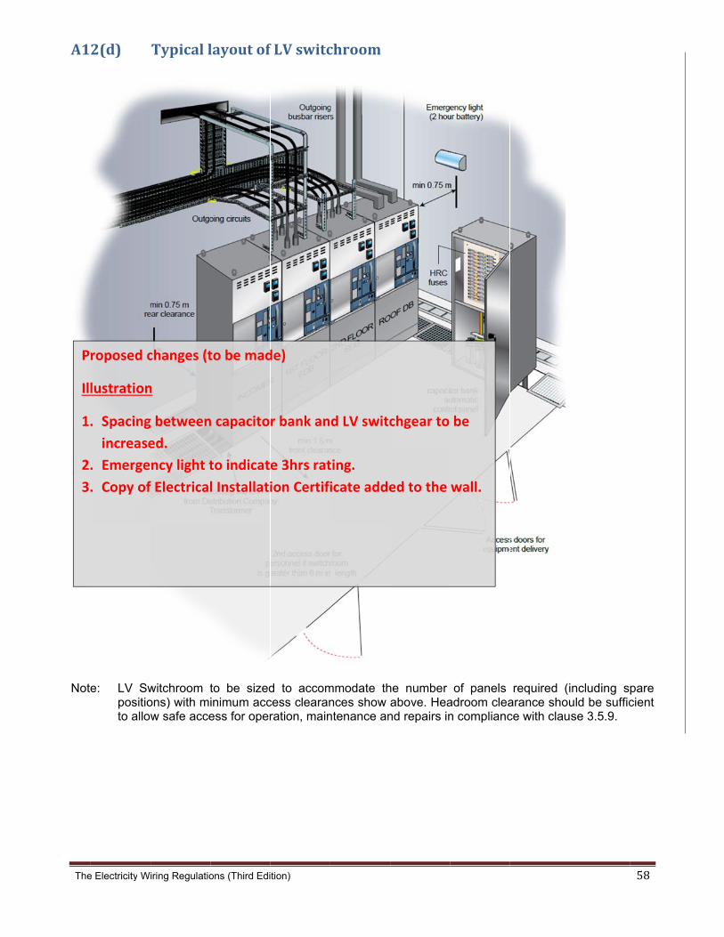
The
A1
Note
P
Ill
1.
2.
3.
e Electricity W
2(d)
e: LV Swpositioto allow
roposed c
lustration
. Spacing
increase
. Emerge
. Copy of
iring Regulatio
Typicall
witchroom tons) with miw safe acce
changes (t
n
g between
ed.
ncy light t
f Electrical
ons (Third Edi
layoutof
to be sizedinimum access for oper
to be mad
n capacito
to indicat
l Installati
tion)
f LVswitc
d to accomcess clearanration, main
de)
r bank an
e 3hrs rat
ion Certifi
chroom
mmodate thnces show ntenance an
d LV switc
ting.
icate adde
he number above. Heand repairs in
chgear to
ed to the
of panels adroom clean complianc
be
wall.
required (iarance shouce with clau
including suld be sufficse 3.5.9.
58
pare cient
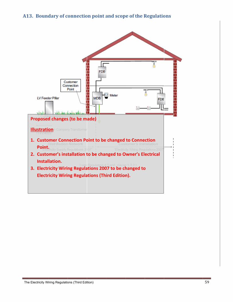
The
A1
e Electricity W
3. Bound
Proposed
Illustratio
1. Custo
Point.
2. Custo
Instal
3. Electr
Electr
iring Regulatio
daryofc
d changes
on
omer Conn
.
omer’s inst
lation.
ricity Wirin
ricity Wirin
ons (Third Edi
onnectio
s (to be m
nection Po
tallation t
ng Regula
ng Regula
tion)
onpointa
ade)
oint to be
to be chan
ations 200
ations (Thi
andscop
changed
nged to O
07 to be ch
ird Edition
eoftheR
to Conne
Owner’s Ele
hanged to
n).
Regulatio
ction
ectrical
o
ons
59
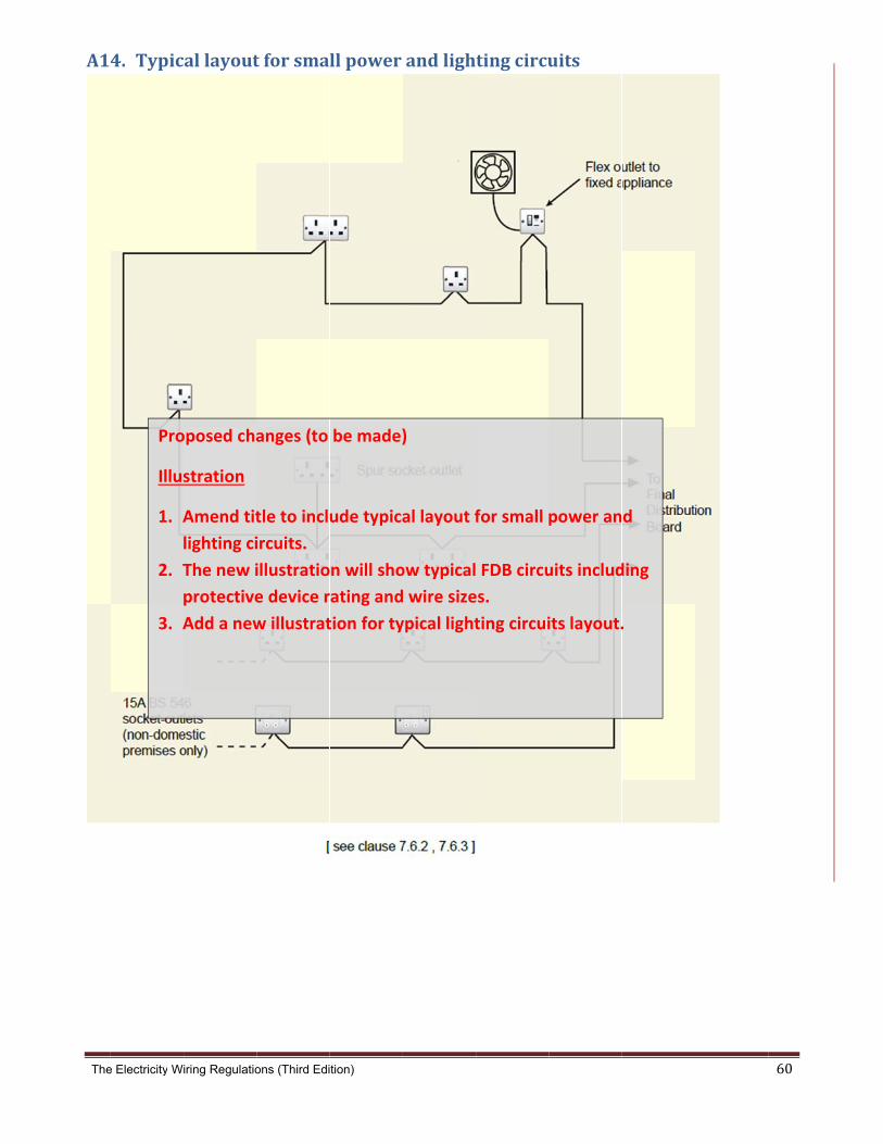
The
A1
e Electricity W
4. Typic
Pro
Illus
1. A
2. T
3. A
iring Regulatio
allayout
oposed cha
stration
Amend tit
lighting ci
The new i
protective
Add a new
ons (Third Edi
tforsma
anges (to
tle to incl
ircuits.
illustratio
e device r
w illustrat
tion)
llpower
be made)
ude typica
n will sho
rating and
tion for ty
andligh
)
al layout f
ow typical
wire size
ypical light
tingcircu
for small p
FDB circu
es.
ting circui
uits
power an
uits includ
its layout.
d
ding
.
60

The
A1
Figur
Figur
e Electricity W
14. Conti
re 1‐ Standard l
re 2 ‐ Two way
iring Regulatio
inued...
lighting circuit
switch lighting
ons (Third Edi
arrangement
g circuit arrange
tion)
ement
61
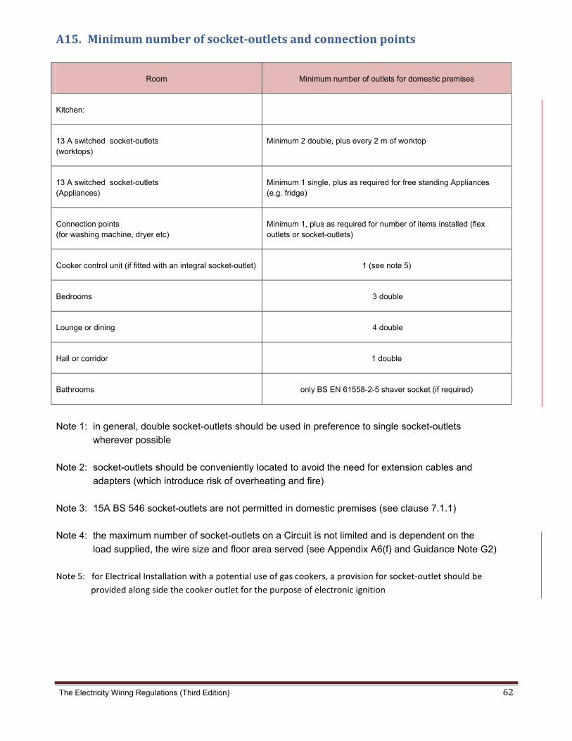
The Electricity Wiring Regulations (Third Edition) 62
A15. Minimumnumberofsocket‐outletsandconnectionpoints
Room Minimum number of outlets for domestic premises
Kitchen:
13 A switched socket-outlets (worktops)
Minimum 2 double, plus every 2 m of worktop
13 A switched socket-outlets (Appliances)
Minimum 1 single, plus as required for free standing Appliances (e.g. fridge)
Connection points (for washing machine, dryer etc)
Minimum 1, plus as required for number of items installed (flex outlets or socket-outlets)
Cooker control unit (if fitted with an integral socket-outlet) 1 (see note 5)
Bedrooms 3 double
Lounge or dining 4 double
Hall or corridor 1 double
Bathrooms only BS EN 61558-2-5 shaver socket (if required)
Note 1: in general, double socket-outlets should be used in preference to single socket-outlets
wherever possible
Note 2: socket-outlets should be conveniently located to avoid the need for extension cables and
adapters (which introduce risk of overheating and fire)
Note 3: 15A BS 546 socket-outlets are not permitted in domestic premises (see clause 7.1.1)
Note 4: the maximum number of socket-outlets on a Circuit is not limited and is dependent on the
load supplied, the wire size and floor area served (see Appendix A6(f) and Guidance Note G2)
Note 5: for Electrical Installation with a potential use of gas cookers, a provision for socket‐outlet should be
provided along side the cooker outlet for the purpose of electronic ignition
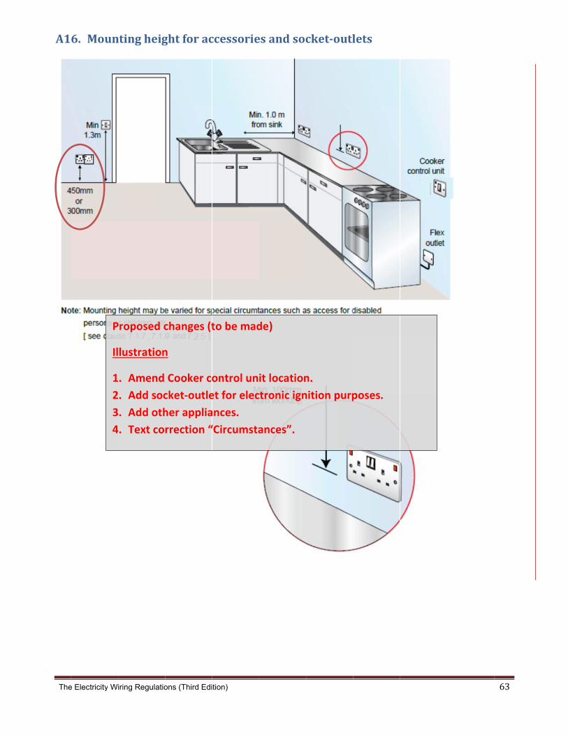
The
A1
e Electricity W
6. Moun
P
Il
1
2
3
4
iring Regulatio
ntingheig
Proposed c
lustration
. Amend
. Add soc
. Add oth
4. Text co
ons (Third Edi
ghtforac
changes (t
n
Cooker co
cket‐outle
her applia
rrection “
tion)
ccessorie
to be mad
ontrol un
et for elec
ances.
“Circumsta
esandsoc
de)
it location
ctronic ign
ances”.
cket‐outl
n.
nition purp
lets
poses.
63
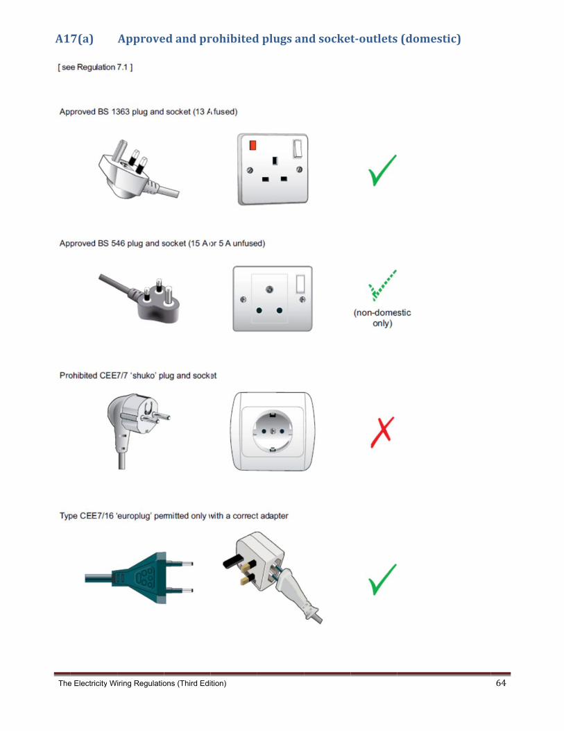
The
A1
e Electricity W
7(a)
iring Regulatio
Approve
ons (Third Edi
edandpr
tion)
rohibited
dplugsan
ndsockett‐outlets(domest
tic)
64

The
A1
e Electricity W
7(b)
Propose
1. Thre
2. Indu
well.
iring Regulatio
Industria
ed change
e phase in
strial sock
.
ons (Third Edi
alplugsa
es (to be m
ndustrial s
ket outlet
tion)
andsock
made)
socket ou
ts with bu
ket‐outlet
utlets to be
ilt in isola
ts
e shown.
ator switc
h to be sh
hown as
65
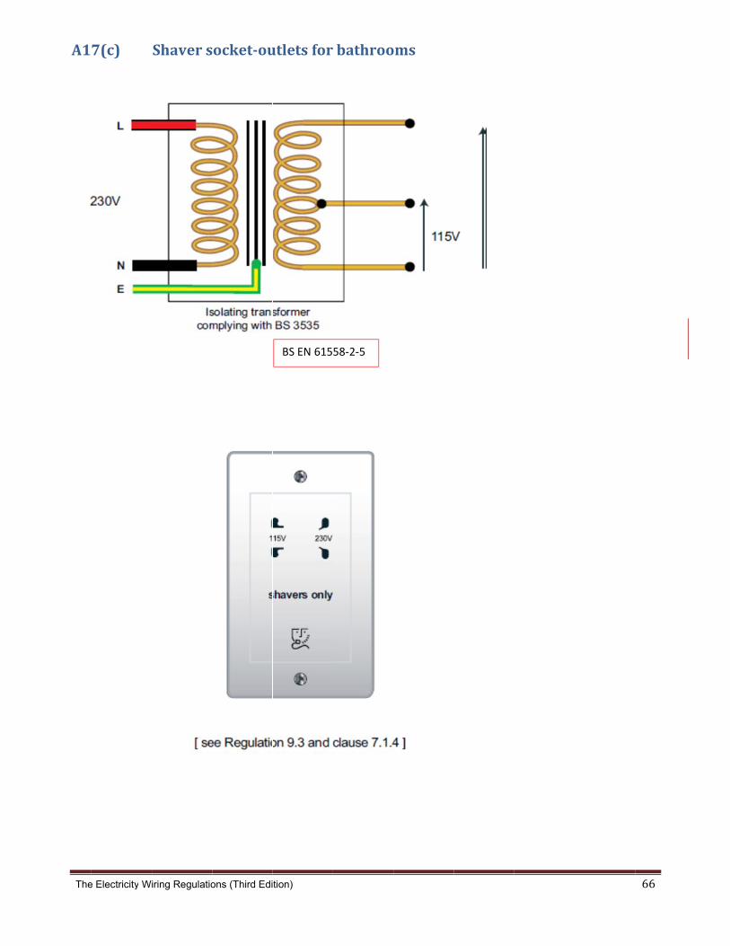
The
A1
e Electricity W
7(c)
iring Regulatio
Shavers
ons (Third Edi
ocket‐ou
tion)
utletsfor
BS EN 615
bathroo
58‐2‐5
oms
66

The
A1
e Electricity W
8(a)
iring Regulatio
ClassIeq
ons (Third Edi
quipmen
tion)
nt(earthe
[ see
edcondu
e clause 6.6.3 ]
uctivepar
rts)
67
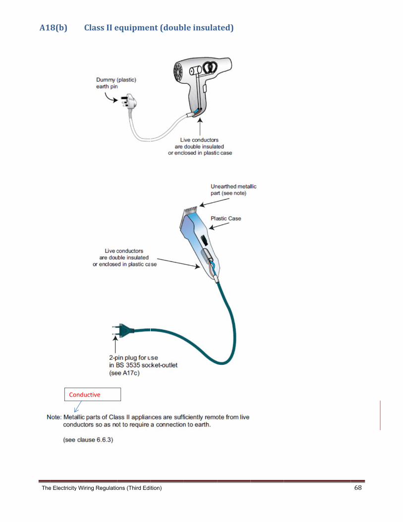
The
A1
e Electricity W
8(b)
Cond
iring Regulatio
ClassIIe
uctive
ons (Third Edi
equipmen
tion)
nt(doub
leinsula
ted)
68
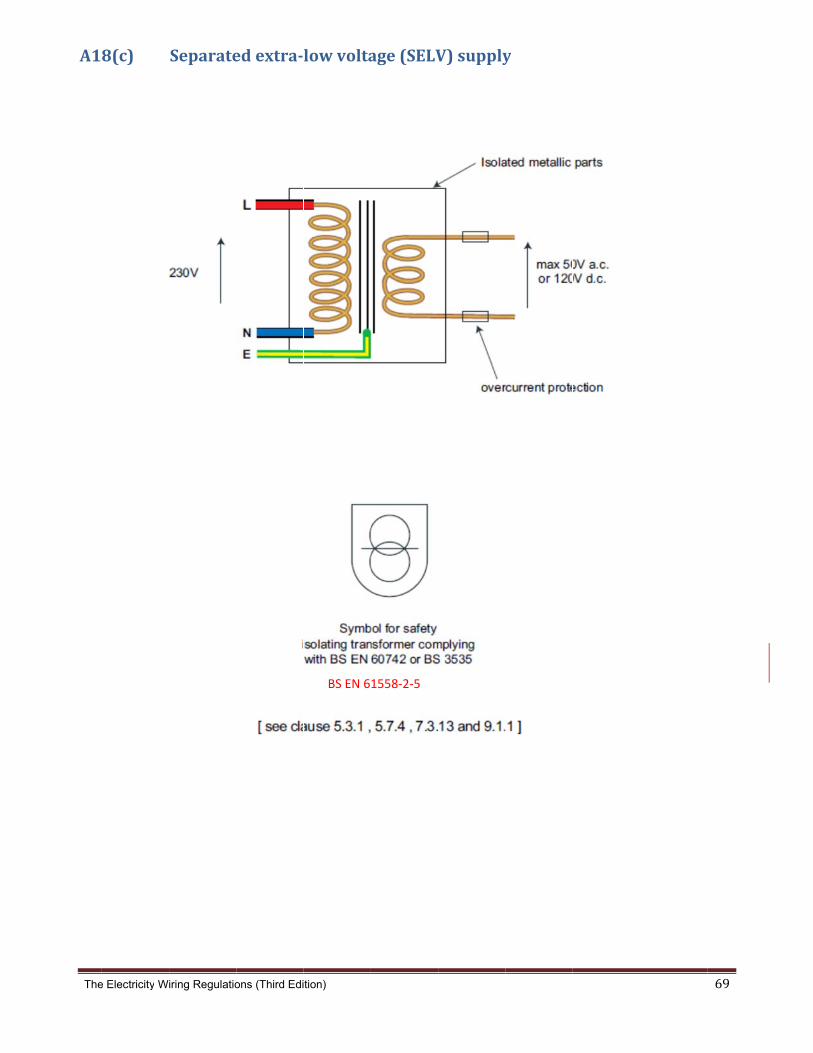
The
A1
e Electricity W
8(c)
iring Regulatio
Separate
ons (Third Edi
edextra‐
tion)
lowvolta
BS EN 6
age(SELV
1558‐2‐5
V)supplyy
69
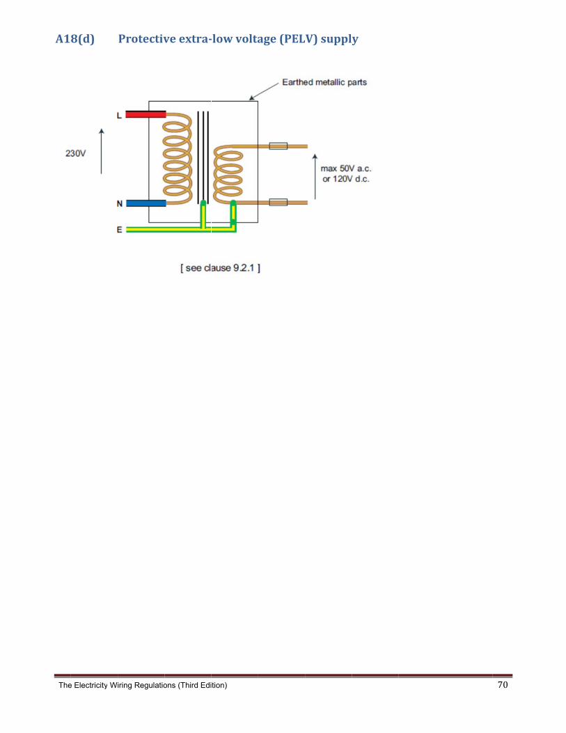
The
A1
e Electricity W
8(d)
iring Regulatio
Protectiv
ons (Third Edi
veextra‐
tion)
‐lowvolta
age(PEL
V)supply
70

The
A1
e Electricity W
8(e)
iring Regulatio
Reduced
ons (Third Edi
dlowvolt
tion)
tage(RLV
V)supply
y
71

The
A1Thes
ded
eart
For c
7671
Met
I.II.
III.
IV.
V.
VI.
Note
e Electricity W
9(a)se Regulatio
icated earth
th fault loop
complete tes
1:2008.
thod 1: mea
a propri auxiliary
electrod an earth
System an addit
achieve due con
out) sufficien
ground t
e1: Where pos
iring Regulatio
Measureons describe
electrode t
impedance v
sting method
asurement
etary earth ey earth spikede under testh resistance v[see Regulattional numbethe requiredsideration sh
nt time shouto improve t
ssible and pra
ons (Third Edi
ementofe three meth
tester, meth
verification.
dology of the
using dedic
electrode tess should be at value of less tion 6.2]. er of electrodd earth resisthould be give
ld be allowedthe earth res
actical method
tion)
earthelehods to me
od 2 uses a
e measurem
cated earth
st device shoapplied at le
than 10 ohm
des may be rtance valueen to future
d if special csistance valu
d 1 should be
ectroderasure the r
dedicated s
ment of earth
h electrode
ould be usedeast 5 m apar
ms is require
required (or
changes in s
hemicals or es
used to meas
resistancesistance of
stakeless ear
electrode re
tester
rt and 5 m di
d for a Local
deeper elect
soil condition
salts are add
sure the resist
ef an earth e
rth electrode
esistance ref
istant from t
lly Earthed
trodes) to
n (e.g. drying
ded to the
tance of an ea
electrode. M
e tester, and
fer to Guidan
the
g
arth electrode
Method 1 us
d method 3
nce Note 3 o
e.
72
ses a
uses
f BS

The
Met
Met
Refe
Pr
1.
2.
e Electricity W
thod 2: mea
I. This
II. This
III. The
test
IV. It is
mea
thod 3: mea
er to Append
roposed c
Introduc
a) Meth
b) Meth
c) Meth
Illustrati
iring Regulatio
asurement
method use
method is u
larger the nu
as the meas
important to
asure and the
asurement
dix A19(b) an
hanges (t
ction of po
hod 1: me
hod 2: me
hod 3: me
ion on me
ons (Third Edi
using dedic
es an earth c
used when th
umber of ea
surement is t
o highlight th
e earth mass
using an ea
nd A19(c).
o be mad
ossible me
asuremen
asuremen
asuremen
ethod 2 w
tion)
cated stake
lamp‐based
here are a nu
rth electrode
the earth ele
hat for this m
s must be pa
arth fault lo
e)
easureme
nt using d
nt using d
nt using a
will be add
eless earth e
tester witho
umber of ear
es the closer
ectrode unde
method to be
rt of the me
oop impeda
ent metho
edicated
edicated
n earth fa
ed.
electrode t
out the need
rth electrode
r the measur
er test in seri
e effective, th
asurement.
ance tester
ods of eart
earth elec
stakeless
ault loop i
ester
to disconne
es and it is no
rement woul
ies with all o
here must be
th electro
ctrode tes
earth ele
mpedanc
ct the earthi
ot possible to
ld be to the e
other earth p
e a loop resis
ode resista
ster.
ctrode tes
e tester.
ing conducto
o use Metho
electrode un
paths in para
stance to
ance
ster.
73
or
od 1
nder
llel

The
A1
e Electricity W
9(b)
iring Regulatio
Measure
ons (Third Edi
ementof
tion)
distribut
tioncom
mpanysuppplyimpedance(
(Ze)
74

The
A1
e Electricity W
9(c)
iring Regulatio
Measure
Propos
1. Wir
2. Con
ons (Third Edi
ementof
sed change
ing to ligh
nect eart
tion)
totalear
es (to be m
hting circu
h and bon
rthfaultl
made)
uit to be a
nding cond
loopimp
mended.
ductors b
edance(
ack.
(Zs)
75

The
A1 Note
1. 2.
3.
Rad 1.
2.
3.
4. 5.
e Electricity W
9(d)
es:
These te
For new energisin
Circuit csee App
dial circuit
This methodfor each circterminals of The polarity to earth, and
If an accesscrossed circ
For lighting c
For metal comeasure R1
iring Regulatio
Circuitc
ests are carr
w Electrical Inng the Electr
continuity testpendix A20(d
ts and ligh
d tests the cocuit by applyithe farthest
can be checd there shoul
ory has beenuits or “borro
circuits the li
onduit circuits+R2.
ons (Third Edi
ontinuity
ied out on de
nstallations, trical Installat
ts must be m).
hting circu
ombined phang short leadconnection p
cked at each ld be no cont
n wired incorowed neutral
ght switches
s the CEC at
tion)
y,(R1+R2
ead circuits.
hese tests sion.
measured for
uits:
se and earthds (not at thepoint or sock
accessory (tinuity betwe
rrectly from a”).
s should be O
t the conduit
2)and(R
The main iso
hould be car
r all circuits a
h resistance (e same time)ket-outlet.
i.e. only one een live and n
another phas
ON to test the
/ back-box s
R1+Rn)te
olator must b
rried out whe
and the resist
(R1+R2) and) at the distri
of the live / neutral.
se or neutral
e wire throug
should be dis
ests
be secured in
en accessorie
tance values
d phase and bution board
neutral term
conductor th
gh the switch
sconnected i
n the off posi
es are in pos
s recorded on
neutral resisd, and measu
inals should
he test will no
h.
n order to ac
ition.
sition but prio
n the test rep
stance (R1+Ruring from the
show contin
ot work (e.g.
ccurately
76
or to
port,
Rn) e
uity
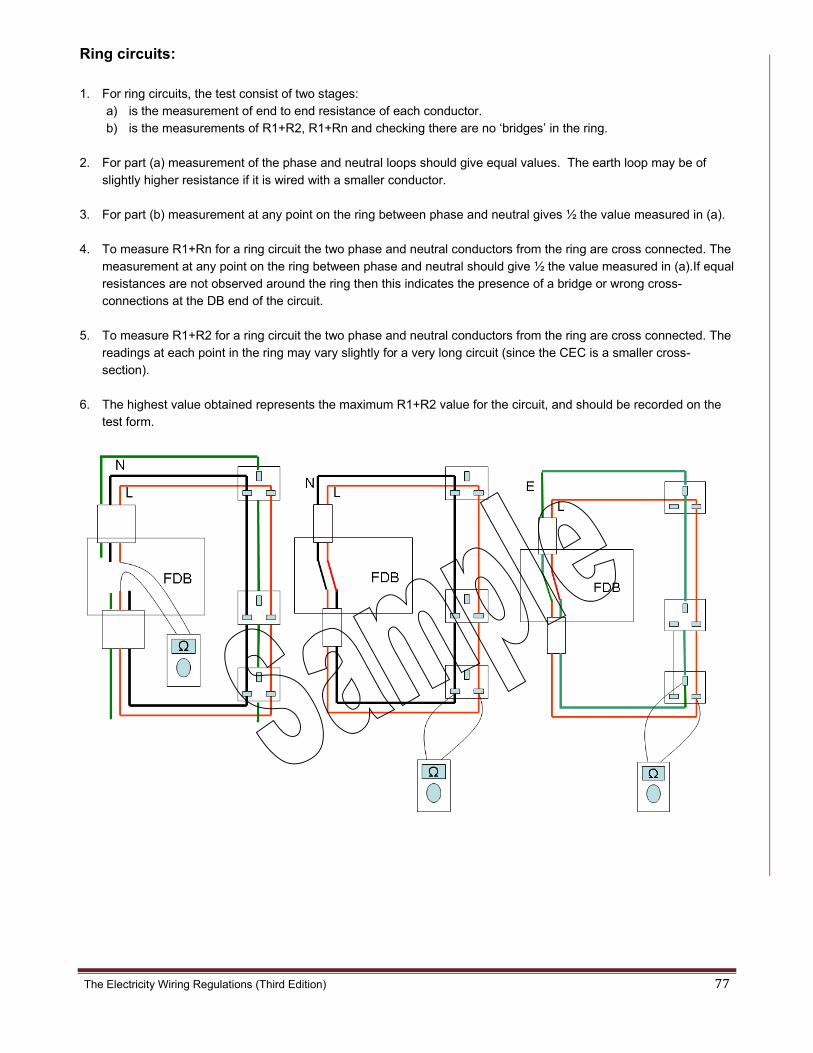
The Electricity Wiring Regulations (Third Edition) 77
Ring circuits: 1. For ring circuits, the test consist of two stages:
a) is the measurement of end to end resistance of each conductor. b) is the measurements of R1+R2, R1+Rn and checking there are no ‘bridges’ in the ring.
2. For part (a) measurement of the phase and neutral loops should give equal values. The earth loop may be of
slightly higher resistance if it is wired with a smaller conductor.
3. For part (b) measurement at any point on the ring between phase and neutral gives ½ the value measured in (a).
4. To measure R1+Rn for a ring circuit the two phase and neutral conductors from the ring are cross connected. The measurement at any point on the ring between phase and neutral should give ½ the value measured in (a).If equal resistances are not observed around the ring then this indicates the presence of a bridge or wrong cross-connections at the DB end of the circuit.
5. To measure R1+R2 for a ring circuit the two phase and neutral conductors from the ring are cross connected. The readings at each point in the ring may vary slightly for a very long circuit (since the CEC is a smaller cross-section).
6. The highest value obtained represents the maximum R1+R2 value for the circuit, and should be recorded on the test form.
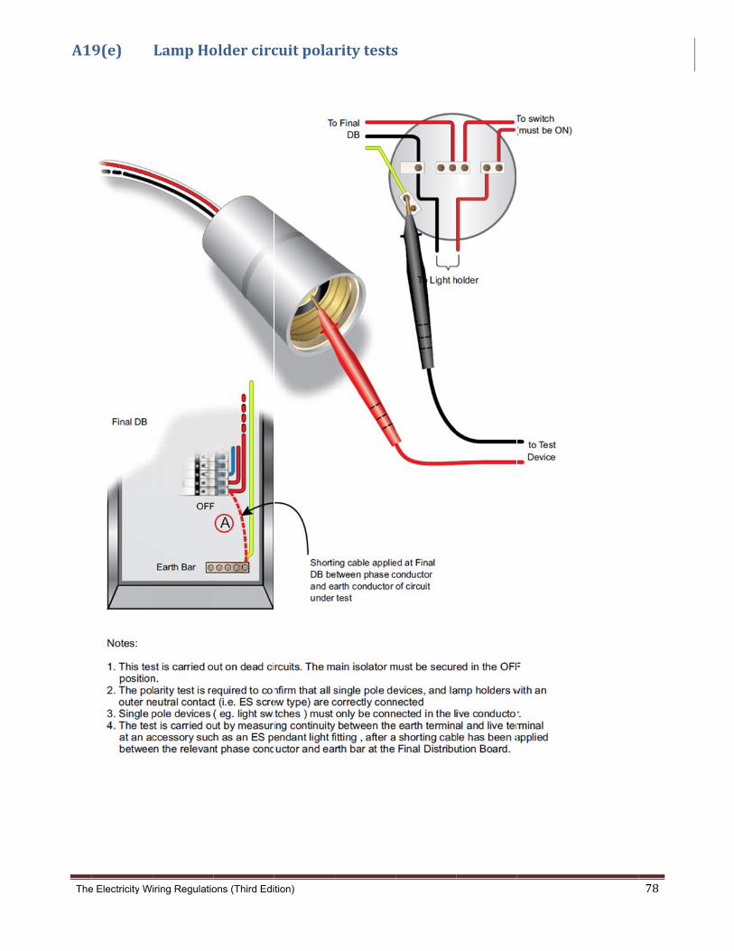
The
A1
e Electricity W
9(e)
iring Regulatio
LampHo
ons (Third Edi
oldercirc
tion)
cuitpolar
ritytests
s
78

The Electricity Wiring Regulations (Third Edition) 79
A19(f) SegregationandInsulationresistancetests
Circuit Nominal Voltage Test Voltage (d.c.)
Minimum insulation resistance (M ohms)
SELV and PELV 250 0.25
up to 500 V 500 0.5
1. Insulation resistance should be checked between all live conductors, and between live conductors and Earth. For SELV and
PELV systems insulation resistance should be measured between the extra-low voltage and higher voltage conductors at 500 V.
2. The test instrument should be capable of producing a d.c. test voltage of 500 V when loaded to 1 mA and be capable of
measurement of up to 200 M ohm.
3. The minimum acceptable value of insulation resistance for any test is 0.5 M ohm for LV systems and 0.25 M ohm for SELV and
PELV systems.
4. The supply should be disconnected and all current-using equipment switched off (including neon indicator lamps, luminaires,
voltmeters, electronic devices such as dimmer switches, starters, RCDs with amplifiers etc). Alternatively, a limited test can be
carried with the phase and neutral conductors connected together and testing to earth.
5. The method of testing requires the connection of all three phases and neutral bar to earth using temporary earth wires.
6. The test measures the insulation resistance of each conductor wire with all other conductors connected to earth. The test is done
with all phase wires, all neutral wires and all earth wires and the values recorded in installation testing report, refer to Appendix
A20(d).
7. This test method checks the segregation of the conductor from all other wires.
8. Insulation measurements should be made at each Distribution Board.

The Electricity Wiring Regulations (Third Edition) 80
A19(g) Sequenceoftestingfornewinstallations
Correct sequence for safe testing
Before supply is connected: 1. Continuity of earth conductors (Main Earth Conductors and Circuit Earth Conductors) 2. Continuity of main and supplementary bonding conductors 3. Continuity of all Circuit conductors 4. Polarity tests of all Circuits 5. Segregation and Insulation resistance measurements of all conductors6. Earth 6. Electrode resistance
After supply is connected: 1. Distribution Company earth fault loop impedance measurement 2. Re-confirm polarity 3. Total earth fault loop impedance measurement 4. Prospective fault current measurement 5. Operation of RCD and earth fault devices 6. Operation of switches and isolators
Note 1: Safety precautions must be observed during testing, including locking off isolators and switches, safeguarding against contact with test voltages, replacement of test links and removal of tools after completion. The order of test sequence must be observed, in particular testing of Earth Conductors (dangerous test voltages can appear on the installation metalwork if Earth Conductors are inadvertently disconnected or broken).
Note 2: testing of RCDs must include measurement of the operating time (ms) at In and at 5 x In, as well as check of non-operation at 50% x In at both 0º and 180º degrees
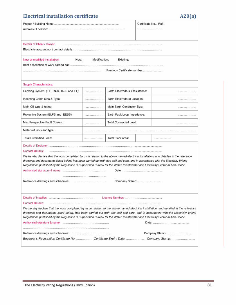
The Electricity Wiring Regulations (Third Edition) 81
Electricalinstallationcertificate A20(a)Project / Building Name:................................................................................
Address / Location: ..............................................................................................
Certificate No. / Ref:
………………….......
Details of Client / Owner: ……………………………………………………………………………...................
Electricity account no. / contact details: ……………………………………………………………………………...
New or modified installation: New: Modification: Existing:
Brief description of work carried out: ……………………………………………………………………………………
………………………………………………………………………. Previous Certificate number:.........................
Supply Characteristics:
Earthing System: (TT, TN-S, TN-S and TT); .........………… Earth Electrode(s )Resistance: ............………
Incoming Cable Size & Type: .........………… Earth Electrode(s) Location: ............………
Main CB type & rating: .........………… Main Earth Conductor Size: ............………
Protective System (ELPS and EEBS); .........………… Earth Fault Loop Impedance: ............………
Max Prospective Fault Current: .........………… Total Connected Load: ............………
Meter ref. no’s and type: . . .. .. . .. .. . .. .. . . . ... . .. .. . .. .. . .. .. .. . . .. . .. .. . .. .. . .. . . .. . ... . .. .. . .. .. . .. .. . . . ... . .. .. . .. .…………
Total Diversified Load: ...................... Total Floor area: ......................
Details of Designer: ……………………………………………………………………………...................................
Contact Details: ……………………………………………………………………………...................................
We hereby declare that the work completed by us in relation to the above named electrical installation, and detailed in the reference
drawings and documents listed below, has been carried out with due skill and care, and in accordance with the Electricity Wiring
Regulations published by the Regulation & Supervision Bureau for the Water, Wastewater and Electricity Sector in Abu Dhabi:
Authorised signatory & name: ……………………………..…..…… Date: …………………….....................
………………………..………..……
Reference drawings and schedules: ………………………….. Company Stamp: …………................
Details of Installer: ...............…………………………… Licence Number: ………………….....................
Contact Details: ……………………………………………………………………..…………………..................
We hereby declare that the work completed by us in relation to the above named electrical installation, and detailed in the reference
drawings and documents listed below, has been carried out with due skill and care, and in accordance with the Electricity Wiring
Regulations published by the Regulation & Supervision Bureau for the Water, Wastewater and Electricity Sector in Abu Dhabi:
Authorised signature & name: ………………………………………… Date: ……………….…....................
………………………………………………………………………….....
Reference drawings and schedules: .....……………………………… Company Stamp: ……………............
Engineer’s Registration Certificate No: ……………. Certificate Expiry Date: ……………...... Company Stamp: ……………...........

The Electricity Wiring Regulations (Third Edition) 82
Inspectionreport(front) A20(b) Project / Building Name:................................................................................
Address / Location: ..............................................................................................
Report No
Details of Client / Owner: ……………………………………………………………………………...................
Electricity account no. / contact details: ……………………………………………………………………………...
New or modified installation: New: Modification: Existing:
Reason for Inspection (first inspection, routine inspection, other):
.................................................................................................................................................................... Installation Certificate
number: …………..
Supply Characteristics:
Earthing System: (TT, TN-S, TN-S and
TT);
.........……… Earth Electrode(s) Resistance: ............………..
Incoming Cable Size & Type: .........……… Earth Electrode(s) Location: ............………..
Main CB type & rating: .........……… Main Earth Conductor Size: ............………..
Protective System (ELPS and EEBS): .........……… Earth Fault Loop Impedance: ............………..
Max Prospective Fault Current: .........……… Total Connected Load: ............………..
Meter ref. no’s and type: .............................................................................................................................
Total Diversified Load: .............................................................................................................................
General Details of Inspection & Testing:
Date of last inspection & test: .......................................................................................................
Any modifications noted: No Yes Details: ........................................................................
Estimated age of installation & estimated age of modifications: ............................................................... Date of next planned
inspection: .......................................................................................................
Any dangerous conditions or urgent work required (give details over leaf): No Yes
Any work or improvements recommended (give details over leaf): No Yes
Extent of inspection: All: Part: Areas not tested / inspected:...........................................................
Inspection carried out by: .…………………………………………………………………………................
Contact Details: …………………………………………………………………………….............
We hereby declare that the inspection and testing completed by us in relation to the above named installation, and detailed over leaf,
has been carried out with due skill and care, and in accordance with the Electricity Wiring Regulations published by the Regulation &
Supervision Bureau for the Water, Wastewater and Electricity Sector in Abu Dhabi:
Authorised signature & name: ……………………………..…..…… Date:……………………....................
Company Stamp: .......................... Engineer’s Registration Certificate No: ……………. Certificate Expiry Date: ……………......
Company Stamp: ……………...........

The
Ins
e Electricity W
spection
iring Regulatio
report(b
ons (Third Edi
back)
tion)
A20(c
83
c)
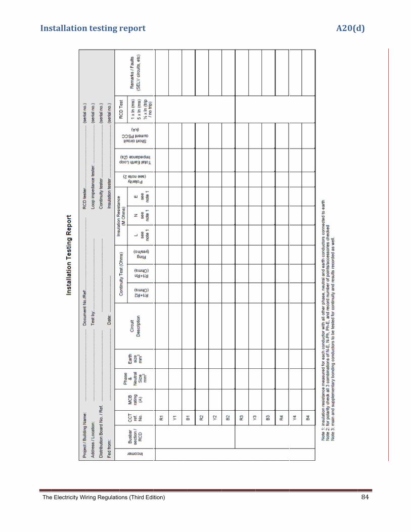
The
Ins
e Electricity W
stallation
iring Regulatio
ntesting
ons (Third Edi
report
tion)
A20(d
84
d)
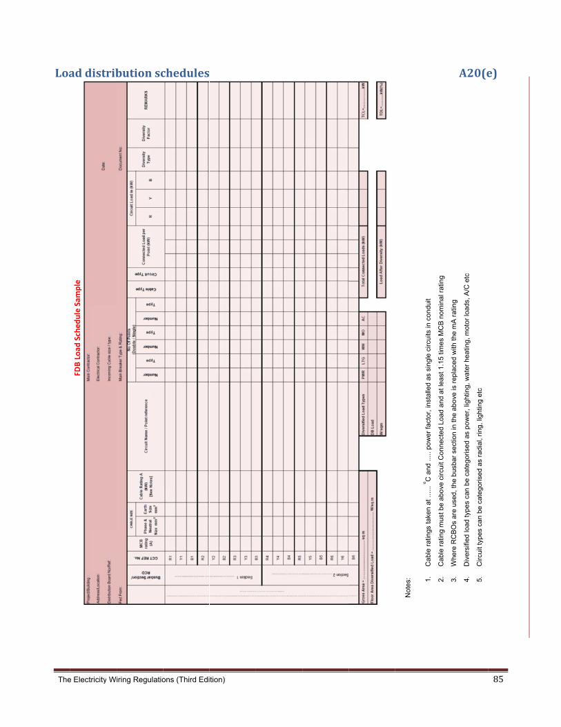
The
Loa
e Electricity W
addistribFD
B Load
Sched
ule Sam
ple
iring Regulatio
butionsc
ons (Third Edi
chedules
tion)
Not
es:
1.C
ab
le r
atin
gs t
ake
n a
t ..
.... o C
and
....
. po
we
r fa
cto
r, in
stal
led
as
sin
gle
cir
cuits
in c
on
duit
2C
ab
lera
ting
mus
tb
ea
bove
circ
uit
Con
nec
ted
Loa
da
nd
atl
ea
st1
15tim
es
MC
Bn
omin
alra
ting
A20(e
2.C
ab
le r
atin
g m
ust
be
abo
ve c
ircu
it C
onn
ecte
d L
oad
an
d a
t le
ast
1.1
5 t
imes
MC
B n
omin
al r
atin
g
3.W
here
RC
BO
s a
re u
sed
, th
e b
usb
ar
sect
ion
in th
e a
bo
ve is
re
plac
ed
with
th
e m
A r
atin
g
4.D
iver
sifie
d lo
ad ty
pes
can
be
cate
gor
ised
as
po
we
r, li
ght
ing,
wa
ter
hea
ting
, mot
or
load
s, A
/C e
tc
5.C
ircu
it ty
pe
s ca
n b
e c
ate
gori
sed
as
rad
ial,
ring
, lig
htin
g e
tc
85
e)

The
A2
e Electricity W
0(e)
Note: SMD
incomer w
Note: MDB
Load.
iring Regulatio
Continue
DB outgoing w
will typically b
B outgoing w
ons (Third Edi
ed…
ways must b
be sized in ac
ways and inco
tion)
be sized in ac
ccordance w
omer will typ
ccordance wi
ith the Diver
pically be size
ith the conne
rsified Load.
ed in accord
ected load a
ance with th
nd SMDB
he Diversified
d
86

The
Sol
SoInsta
Desc
Strin
Arra
Arra(as s
Strincurrprot
Wiri
Strin
Pola
Arraresis
Eart
Swit
Inve
Inve
Inve
Loss
Detai
Conta
We h
docum
Regu
Autho
Refer
Detai
Conta
We h
docum
Regu
Autho
………
Refer
e Electricity W
larPVTe
olar PV allation addr
cription of w
ng
ay
ay parameterspecified)
ng over‐rent tective devic
ing
ng test
arity check
ay insulation stance
h Continuity
tchgear func
erter make /
erter serial nu
erter function
s of mains te
ils of Designer:
act Details:
hereby declare t
ments listed bel
ulation & Superv
orised signatory
rence drawings
ils of Installer:
act Details:
hereby declare
ments listed be
ulation & Superv
orised signature
…………………
rence drawings
Proposed
1. New g
2. A new
3. A new
iring Regulatio
estRepor
Test Reress
work under te
Module
Quantity
rs Voc (stc
Isc (stc)
e
Type
Rating (A
DC Ratin
Capacity
Type
Phase (m
Earth (m
Voc (V)
Isc (A)
Irradian
Test Vol
Pos – Ea
Neg – Ea
y (where fitte
tioning corre
model
umber
ns correctly
st
…………………
…………………
that the work co
low, has been c
vision Bureau fo
y & name: ………
………
and schedules
...............………
…………………
that the work
low, has been c
vision Bureau fo
& name: ………
…………………
and schedules
d changes
guidance n
w test repo
w inspectio
ons (Third Edi
rt
eport
est
y
)
A)
ng (V)
y (kA)
mm²)
mm²)
ce
ltage (V)
arth (MΩ)
arth (MΩ)
ed)
ectly
……………………
……………………
ompleted by us i
carried out with
or the Water, Wa
…………………
…………………
: ……………
……………………
……………………
completed by u
carried out with
or the Water, Wa
…………………
……………………
: .....……………
(Sample p
notes A20
ort.
on report.
tion)
1 2
…………………
…………………
in relation to the
due skill and ca
Wastewater and E
……..…..……
..………..……
………………..
…… Lice
…………………
us in relation t
due skill and ca
Wastewater and E
…………………
………………....
……………………
provided)
0(f) and A2
.
3
…………………
…………………
e above named
are, and in acco
Electricity Secto
Date: ……
Company
nce Number: …
………………..…
o the above na
are, and in acco
Electricity Secto
… Date: ……
..
… Company
)
20 (g) on s
Init Per
Referenc
Date
Inspecto
Test Inst
4
……….................
……….................
installation, and
ordance with the
or in Abu Dhabi:
…………………..
y Stamp: ………
…………………..
…………………
amed installatio
ordance with the
or in Abu Dhabi:
…………….…....
Stamp: …………
solar PV t
ial Verificatioiodic Verifica
ce
or
truments
...................
...................
d detailed in the
e Electricity Wirin
:
....................
…................
...................
..................
on, and detailed
e Electricity Wiri
:
................
……............
esting and
on ation
n
e reference draw
ng Regulations
d in the referen
ring Regulations
d inspecti
A20
wings and
published by th
nce drawings a
s published by t
ion.
87
0(f)
he
and
the

The Electricity Wiring Regulations (Third Edition) 88
SolarPVsysteminspectionreport A20(g)
Solar PV Inspection Report Initial Verification Periodic Verification
Installation address Reference:
Date:
Circuits inspected Inspector :
Equipment/Circuits Inspected: satisfactory not satisfactory (give details /comments)
not applicable urgent work required
General
a.c part of the electrical installation is tested
in accordance with Regulations 8.1
PV distribution boards room condition
PV distribution boards condition
Proper ventilation behind array
Cable entry weatherproof
Array frame correctly fixed and stable; roof
fixings weatherproof
PV array design and installation
All d.c. components are rated for continuous
operation at d.c. and at the maximum
possible d.c. system voltage and maximum
possible d.c.
Protection by use of class II insulation
adopted on the DC side
PV string cables and PV d.c. main cables are
black in colour and double insulated
Wiring systems have been selected and
erected to withstand the expected external
influences such as wind, temperature and
solar radiation
String cables are sized to accommodate the
maximum fault current
If applicable, string over-current protective
devices are fitted and correctly specified.
Verification of a d.c. switch disconnector is
fitted to the d.c. side of the inverter
If applicable, where blocking diodes are fitted
the reverse voltage rating is at least 2 × Voc
stc of the PV string in which they are fitted.
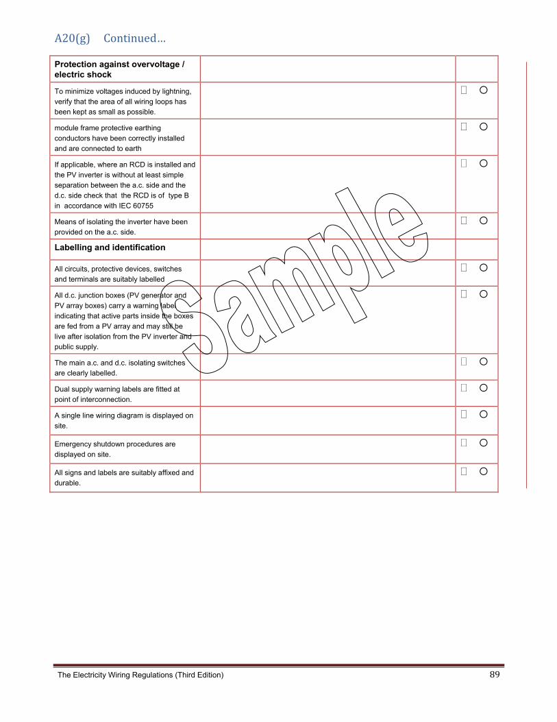
The Electricity Wiring Regulations (Third Edition) 89
A20(g)Continued…
Protection against overvoltage / electric shock
To minimize voltages induced by lightning,
verify that the area of all wiring loops has
been kept as small as possible.
module frame protective earthing
conductors have been correctly installed
and are connected to earth
If applicable, where an RCD is installed and
the PV inverter is without at least simple
separation between the a.c. side and the
d.c. side check that the RCD is of type B
in accordance with IEC 60755
Means of isolating the inverter have been
provided on the a.c. side.
Labelling and identification
All circuits, protective devices, switches
and terminals are suitably labelled
All d.c. junction boxes (PV generator and
PV array boxes) carry a warning label
indicating that active parts inside the boxes
are fed from a PV array and may still be
live after isolation from the PV inverter and
public supply.
The main a.c. and d.c. isolating switches
are clearly labelled.
Dual supply warning labels are fitted at
point of interconnection.
A single line wiring diagram is displayed on
site.
Emergency shutdown procedures are
displayed on site.
All signs and labels are suitably affixed and
durable.

The
A2Con
e Electricity W
1.Genernnection to
RC
DB
DB
Note
Propose
1. New
arran
iring Regulatio
ralMarino mains su
CBO (30mA)
RCBO (30mA)
e [protection
ed change
w guidance
ngements
ons (Third Edi
nasconnepply (singl
2 pole
M
4 pole swi
n can be prov
M
es (to be m
e notes A2
s.
tion)
ectionare phase an
e switch
RCBO (10mA
Marina Pedestal
RCBO (10mA)
tch
vided by a co
Marina Pedestal
made)
21 to be a
rrangemend three ph
A)Singl
Singl
Singl
Singl
Singl
Thre
Thre
Singl
Singl
ombination o
Sing
dded to s
entshase)
e phase industria
e phase industria
e phase industria
le phase industria
le phase light
ee phase industria
ee phase industria
le phase industri
le phase industri
of suitably ra
le phase light
show gene
al socket outlet
al socket outlet
al socket outlet
al socket outlet
al socket outlet
al socket outlet
ial socket outlet
ial socket outlet
ated MCBs an
eral Marin
nd
nas conne
ection
90

The
A2
P
1
e Electricity W
2.Gener
Proposed
1. New gu
arrage
Sing
conn
iring Regulatio
ralsolarP
changes
uidance n
ments.
gle solar PV s
nected in ser
ons (Third Edi
PVconne
(to be illu
notes A22
tring
ries
tion)
ectionar
ustrated)
to be illus
rrangeme
strated to
ents
o show general sola
ar PV conn
nection
91
The Electricity Wiring Regulations (Third Edition) 92
Guidancenotes

The Electricity Wiring Regulations (Third Edition) 93
Guidancenotes GG1. Guidance note on supply voltage change 95
G2. Estimation of connected load and diversity factors 96
G3. Photographs
(a) Photograph of busbar riser 100
(b) Photograph of final distribution
(horizontal DIN rail) 101
(c) Photograph of final distribution board
(vertical, split busbar type) 102
G4. Electric shock, ELP and EEB systems
(a) Direct contact with electricity 103
(b) Indirect contact with electricity 104
(c) Main and supplementary earthed equipotential bonding (EEB) 105
(d) Illustration of earth leakage protected system (ELPS) 106
(e) Grading of RCDs in an ELP system 107
(f) ELP system supplied from LV switchroom 108
(g) Calculation of touch voltage (ELP system) 109
(h) Calculation of touch voltage (EEB system) 110
G5. Electric shock and RCD characteristics
(a) RCD operating characteristics and electric shock 111
(b) Typical values of body resistance and physiological effects 112
(c) RCD operating principle 113
(d) Types of RCDs 114
(e) Sources of nuisance tripping of RCDs 115

The Electricity Wiring Regulations (Third Edition) 94
G6. Protection of buried cables 116
G7. Common errors
(a) Exposed unsheathed cables at termination points 117
(b) Protection of high temperature connections 118
(c) Weather protected outdoor socket-outlets 119
(d) Earth tails in accessories and connection boxes 120
(e) Minimum depth of buried plastic conduit 121
(f) Circuit identification numbers on accessories and earth conductors 122
(g) Missing grommets and sharp edges on cable tray 123
(h) Cables in ceiling-voids 124
(i) Cable glands for earthing of armoured cable 125
(j) Earth continuity connections across cable tray and conduit 126
(k) Prohibited terminal blocks and taped connections 127
(l) Slotting of steel gland plates for single core cables 128
(m) Flex-outlets 129
G8. Typical lighting circuit connections 130
G9. Isolation and switching 131
G10 Changes in the Third Edition (Jan 2014) 132
The
G1 Distsystwithwith+10 The(claopevoltadrop
e Electricity W
Guida
tribution Cotem. Previ
h an allowedh BS EN 500% -6%.
ese Regulatuse 4.1.3).
erate withouage drop op to Applian
iring Regulatio
ancenote
ompanies inously, the vd variation 160) the su
tions have This rang
ut modificatf 4% within
nces will not
ons (Third Edi
eonsupp
n the UAE hvoltage of sin voltage o
upply voltag
adopted thge has beenion, and als
n an Ownert exceed 10
tion)
plyvoltag
have traditiosupply wasof +/- 6%. Wge is 230 / 4
he same non adopted so providesr’s Electrica0% of the no
gechange
onally base declared t
With the har400 V +/- 10
ominal voltto allow exs a superioal Installatioominal volta
BS
Ra
the
e
ed the desigto be 240 Vrmonization0%. In the U
tage of supxisting distrior voltage raon (clause age of 230/
EN 50160 su
nge of suppl
ese Regulatio
gn of their nV single-phan of supply UK, the vari
pply with a bution netwange to Cu7.5.10) this/400 V.
upply voltage
ly voltage ad
ons
networks onase or 415 voltages in iation is cur
variation owork assetsustomers. Ws ensures th
e
dopted in
n the UK poV three phEurope (in
rrently limite
of +10% -s to continuWith an allohe total vol
95
ower hase, n line ed to
- 6% ue to owed tage

The Electricity Wiring Regulations (Third Edition) 96
G2 Estimationofconnectedloadanddiversityfactors
LoaddiversityWhere a Circuit consists of multiple points of utilization (e.g. socket outlets), the Circuit load current can be assessed by simply adding the individual full load current of all points of utilization. While, this would provide a conservative design, it will lead to over sizing the Circuit because in reality the sum of individual loads rarely equal to the actual load current required by the Circuit. This is known as load diversity. For example, the load seen at the sub main distribution board that is feeding multiple apartments in a residential building will rarely see all apartments at full load at the same time. Therefore, allowances for diversity between loads must be taken into consideration in sizing final Circuits and other distribution Circuits. Moreover, certain Appliances such as a washing machine have a number of components that may be independently controlled and vary over time. Therefore, over the duration of the wash cycle, the total demand will not always be maintained at the full load rating, as various components switch in and out. The allowances for diversity in an Electrical Installation varies depending on many factors, these factors may include: (a) Type and nature of the Electrical Installation (residential, commercial, industrial, etc); (b) Intended use of utilization points (e.g. general use socket‐outlets for the connection of portable appliances
compared to dedicated socket‐outlets for a fixed connection); (c) Number of utilization points in a Circuit (e.g. a SMBD feed two FDBs compared to 10 FDBs);and (d) Operating characteristics of the connected load (e.g. AC units in Abu Dhabi is essential in the summer and in
many cases it will be running most of the time). It is important to note that allowances for diversity in an Electrical Installation may vary between similar installation. Therefore, the designer of the Electrical Installation may select different allowances representing the intensity of usage (e.g. higher value for high usage Circuits, such as communal kitchens, lower value for lower occupancy dwellings, etc). This Guidance Note provides diversity allowances for specific situations, the factors used may be increased or
decreased by the designer depending on the intended design of the Electrical Installation and provide the relevant
justification to the Distribution Company.
SizingoffinalcircuitsAs indicated in Clause 5.2.5 and Appendix A6(f), the relationship between the Circuit load current (Ic), the protective
device nominal current rating (In), and the current carrying capacity of the Circuit conductors (Id) is as follows:
Ic ≤ In ≤ Id In addition;
Id ≥ 1.15 x In (cables must selected with ratings at least 1.15 times the protective device nominal current rating)
For example, the Circuit full load current of a single phase 4kW Appliance, can be calculated using the following
formula (power factor = 1 for resistive load):
Current (Ic) =
Current (Ic) =
= 17.4 A
Therefore, the protective device nominal current rating (In) must not be less than 20A (nearest standard rating), and the current carrying capacity for the Circuit conductor (Id) must be not less than 23A (20A X 1.15), assuming grouping and temperature rating factors to be 1. The above calculation ensures that the Circuit is suitably rated for the Appliance to draw 17.4A for a continuous period of time.
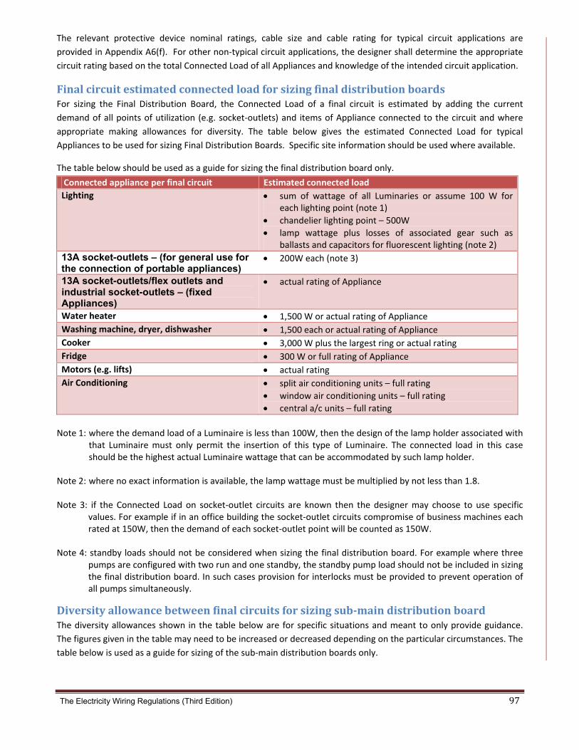
The Electricity Wiring Regulations (Third Edition) 97
The relevant protective device nominal ratings, cable size and cable rating for typical circuit applications are
provided in Appendix A6(f). For other non‐typical circuit applications, the designer shall determine the appropriate
circuit rating based on the total Connected Load of all Appliances and knowledge of the intended circuit application.
FinalcircuitestimatedconnectedloadforsizingfinaldistributionboardsFor sizing the Final Distribution Board, the Connected Load of a final circuit is estimated by adding the current
demand of all points of utilization (e.g. socket‐outlets) and items of Appliance connected to the circuit and where
appropriate making allowances for diversity. The table below gives the estimated Connected Load for typical
Appliances to be used for sizing Final Distribution Boards. Specific site information should be used where available.
The table below should be used as a guide for sizing the final distribution board only.
Connected appliance per final circuit Estimated connected load
Lighting sum of wattage of all Luminaries or assume 100 W for each lighting point (note 1)
chandelier lighting point – 500W
lamp wattage plus losses of associated gear such as ballasts and capacitors for fluorescent lighting (note 2)
13A socket-outlets – (for general use for the connection of portable appliances)
200W each (note 3)
13A socket-outlets/flex outlets and industrial socket-outlets – (fixed Appliances)
actual rating of Appliance
Water heater 1,500 W or actual rating of Appliance
Washing machine, dryer, dishwasher 1,500 each or actual rating of Appliance
Cooker 3,000 W plus the largest ring or actual rating
Fridge 300 W or full rating of Appliance
Motors (e.g. lifts) actual rating
Air Conditioning split air conditioning units – full rating
window air conditioning units – full rating
central a/c units – full rating
Note 1: where the demand load of a Luminaire is less than 100W, then the design of the lamp holder associated with
that Luminaire must only permit the insertion of this type of Luminaire. The connected load in this case should be the highest actual Luminaire wattage that can be accommodated by such lamp holder.
Note 2: where no exact information is available, the lamp wattage must be multiplied by not less than 1.8. Note 3: if the Connected Load on socket‐outlet circuits are known then the designer may choose to use specific
values. For example if in an office building the socket‐outlet circuits compromise of business machines each rated at 150W, then the demand of each socket‐outlet point will be counted as 150W.
Note 4: standby loads should not be considered when sizing the final distribution board. For example where three
pumps are configured with two run and one standby, the standby pump load should not be included in sizing the final distribution board. In such cases provision for interlocks must be provided to prevent operation of all pumps simultaneously.
Diversityallowancebetweenfinalcircuitsforsizingsub‐maindistributionboardThe diversity allowances shown in the table below are for specific situations and meant to only provide guidance.
The figures given in the table may need to be increased or decreased depending on the particular circumstances. The
table below is used as a guide for sizing of the sub‐main distribution boards only.
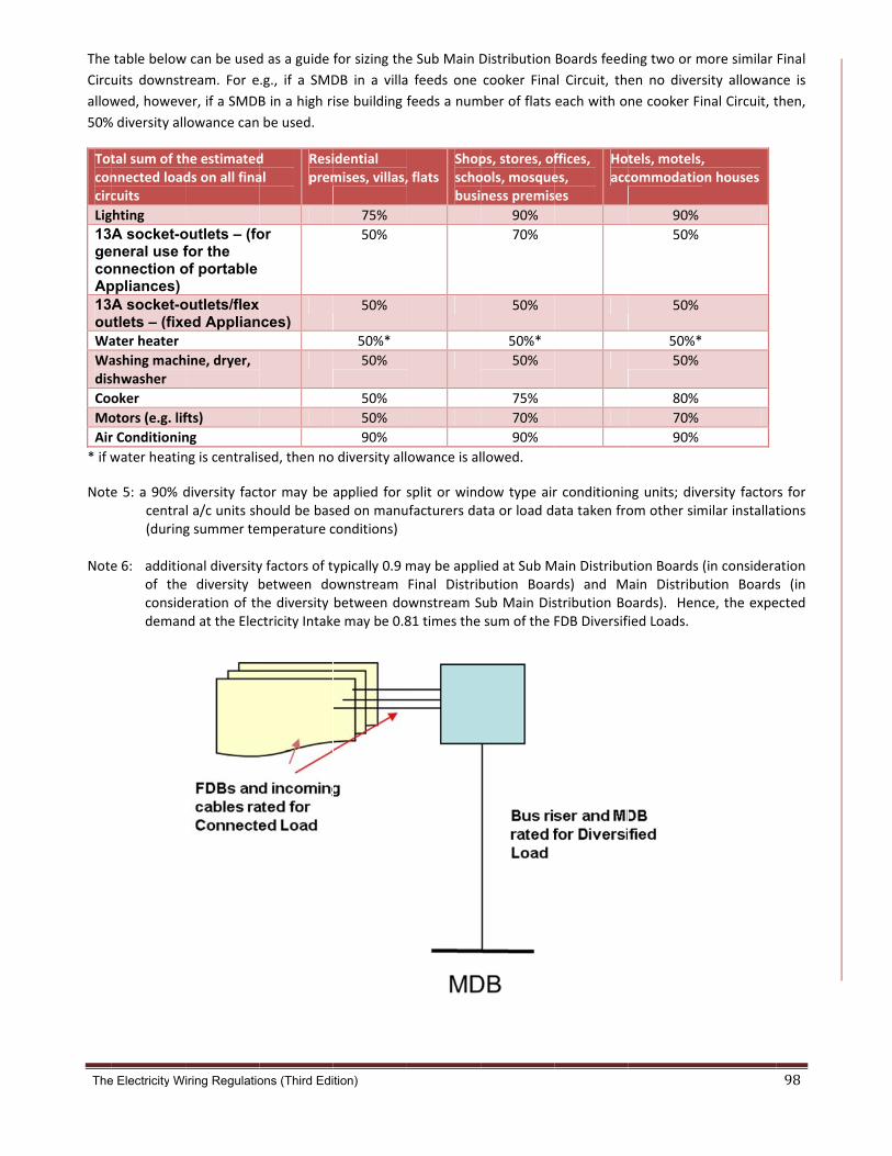
The
The
Circu
allow
50%
Totconcirc
Lig
13AgecoAp13AouWa
Wadis
Coo
Mo
Air
* if w
Note
Note
e Electricity W
table below
uits downstr
wed, howeve
% diversity all
tal sum of thnnected loadcuits
ghting
A socket-oeneral use fonnection oppliances) A socket-o
utlets – (fixeater heater
ashing machshwasher
oker
otors (e.g. lif
r Conditionin
water heatin
e 5: a 90% dcentra(during
e 6: additioof theconsidedeman
iring Regulatio
w can be used
ream. For e
er, if a SMDB
lowance can
he estimatedds on all fina
outlets – (fofor the of portable
outlets/flex ed Applian
hine, dryer,
fts)
ng
ng is centralis
diversity factl a/c units shg summer te
onal diversitye diversity beration of thnd at the Elec
ons (Third Edi
d as a guide
.g., if a SMD
B in a high r
be used.
d al
Resiprem
or
nces)
sed, then no
tor may be hould be basemperature c
y factors of tbetween dohe diversity ctricity Intak
tion)
for sizing the
DB in a villa
ise building f
idential mises, villas,
75%
50%
50%
50%*
50%
50%
50%
90%
o diversity all
applied for ssed on manuconditions)
ypically 0.9 mownstream between doe may be 0.8
e Sub Main D
a feeds one
feeds a num
, flats Shopschobusi
owance is al
split or windufacturers da
may be applFinal Distribownstream S81 times the
Distribution
cooker Fina
mber of flats
ps, stores, ofools, mosqueness premis
90%
70%
50%
50%*
50%
75%
70%
90%
llowed.
dow type airata or load d
ied at Sub Mbution BoarSub Main Dissum of the
Boards feed
al Circuit, the
each with o
ffices, es, es
Hotacc
r conditioninata taken fro
Main Distributrds) and Mstribution BoFDB Diversif
ing two or m
en no divers
ne cooker Fi
tels, motels,commodatio
90%
50%
50%
50%*
50%
80%
70%
90%
ng units; diveom other sim
tion Boards ain Distribuoards). Hencied Loads.
more similar
sity allowan
inal Circuit, t
, on houses
ersity factormilar installat
(in consideraution Boardsce, the expe
98
Final
ce is
then,
rs for tions
ation s (in ected

The
PowThe The for vinclu
Do
Off
Ho
Sho
Car
Car
Note
Note
A
1
e Electricity W
werdemcalculated Dfollowing tavarious premuding weath
P
mestic
fices
tels
ops
r Parks (open
r Park (basem
e: during sum
e: the above
Additional
1. A comp
provide
premise
iring Regulatio
mandDiversified Lable providesmise types at er, occupanc
remise Type
n air)
ment withou
mmer air con
e figures repr
l changes
plete work
e further g
es.
ons (Third Edi
oad for Prems some guidaMDB level. cy hours, use
e
ut a/c)
nditioning m
resents powe
(to be ma
ked exam
guidance
tion)
mises shouldance to the tIt is importae of smart te
Ran
1
4
ake up 70%
er demand v
ade)
ple will be
on diversi
d be checkedtotal demandnt to note thechnology, an
Powe
nge W/m²
30‐80
100‐150
75‐100
40‐100
0‐10
10‐20
to 80% of th
values at buil
e included
ify factors
d against eled for lightinghat the valuend building m
er Demand
Aver
he total powe
ldings plot le
d in this se
s in typica
ectricity usagg and small pes below depmanagement
rage W/m²
55
125
88
70
5
15
er demand.
evel.
ection to
al
ge data for spower (with pends on a nt system.
similar Premair conditionumber of fac
99
mises. ning) ctors

The
G3
Electricity Wir
(a)
Proposed
1. Photo
ring Regulatio
Photogra
d changes
o to be am
ns (Third Edit
aphofbu
s (to be m
mended fo
ion)
usbarris
ade)
or clarity r
er
reasons.
100

The
G3
Electricity Wir
(b)
Propos
1. Pho
ring Regulatio
Photogra(horizon
sed chang
oto to be a
ns (Third Edit
aphoffinntalDINr
ges (to be
amended
ion)
naldistrirail)
made)
for clarity
butionb
y reasons
oards
.
101
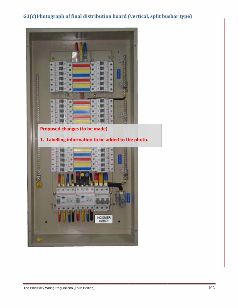
The
G3
Electricity Wir
(c)Photo
Prop
1. La
ring Regulatio
ographof
posed cha
abelling in
ns (Third Edit
ffinaldis
nges (to b
nformatio
ion)
stribution
be made)
on to be ad
nboard(
dded to th
(vertical
he photo.
,splitbu
.
usbartyp
e)
102

The
G4
Electricity Wir
(a)
ring Regulatio
Directco
ns (Third Edit
ontactwi
ion)
ithelectr
ricity
103

The
G4
Electricity Wir
(b)
Pro
1.
ring Regulatio
Indirect
oposed ch
Termino
Conduct
ns (Third Edit
contactw
hanges (to
logy chan
ive‐Part”
ion)
withelec
o be made
nged chang
and Extra
ctricity
e)
ged for “E
anenous‐C
Exposed‐
Conductiv‐‐Part”.
104

The
G4
Prop
Illust
1. T
2. M
3. A
Note
Note Note Note
Electricity Wir
(c)Main
posed cha
tration
To be ame
MEC to be
Additional
es:
e 1. Live c
e 2. Chara agains circuit applia time f
e 3. Clamp
ring Regulatio
andsupp
anges (to b
ended for
changed
l illustratio
onductor
acteristics st earth lot A (sockeances). Alsfor distrib
ps for eart
ns (Third Edit
plementa
be made)
clarity rea
to CEC.
on on bon
s are not
of MCBs oop impedet‐outlet sso, MCCBsution circ
thing and
ion)
aryearth
asons.
nding of co
shown fo
for Final Ddance valuupplying s must cocuits. ( see
bonding
hedequip
onductors
r clarity.
Distributioues to givportable aordinate te clause 5.
shall be in
potential
s.
on Boardsve a maximapplianceto give a m.5.2 and 5
n accorda
bonding
s must be mum of 0.es) for circmaximum5.5.3 )
nce with
g(EEB)
coordina4 sec tripcuit B (fixem of 0.4 se
BS 951.
ted ping for ed ec tripping
105
g
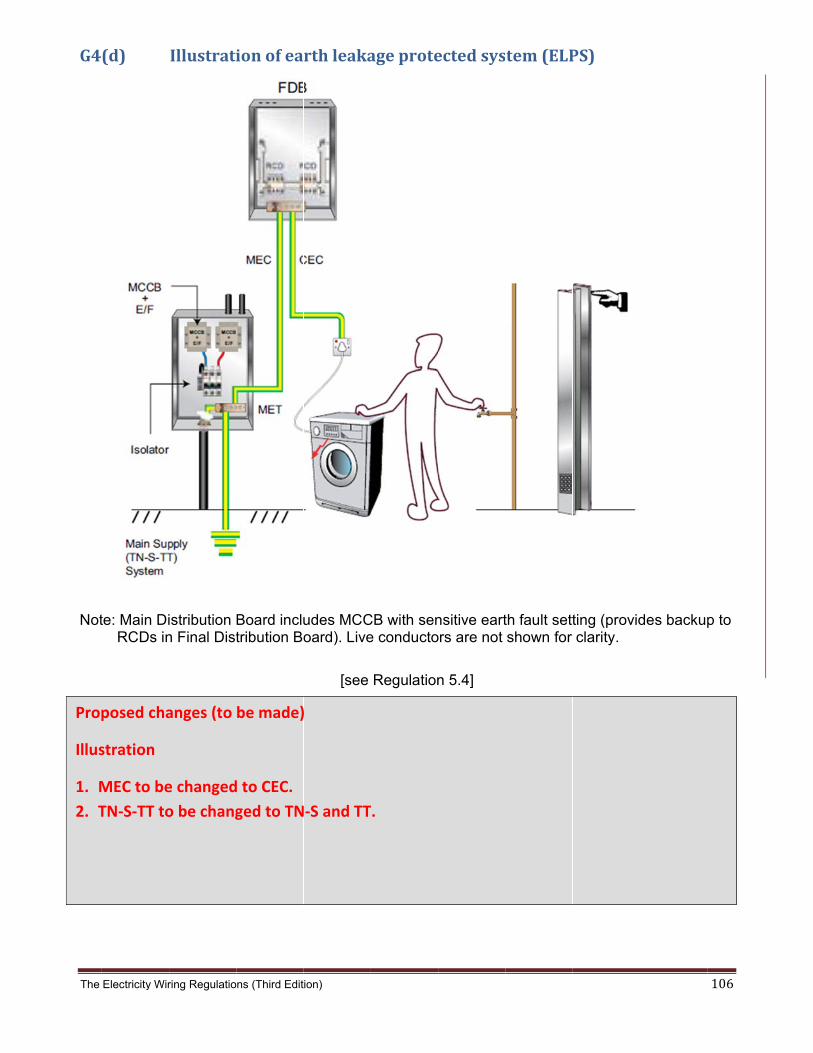
The
G4
Not
Prop
Illus
1. M
2. T
Electricity Wir
(d)
te: Main Di RCDs in
posed cha
stration
MEC to be
TN‐S‐TT to
ring Regulatio
Illustrati
istribution n Final Dist
anges (to
e changed
o be chang
ns (Third Edit
ionofea
Board inclutribution Bo
be made)
d to CEC.
ged to TN
ion)
rthleaka
udes MCCoard). Live
[see
)
N‐S and TT
ageprote
CB with sene conducto
Regulation
T.
ectedsys
nsitive eartors are not
n 5.4]
tem(ELP
th fault settshown for
PS)
ting (providclarity.
des backup
106
p to

The
G4
Not Not
Electricity Wir
(e)
te 1: Type Final earth
te 2: A max applia circuit
Prop
Illust
1. Li
Note
1. Ad
ring Regulatio
Grading
S RCDs pDistributiofault (E/F)
ximum of 3nces; a mas
osed chan
tration
ghting cir
es:
dded text
ns (Third Edit
ofRCDs
rovide timeon Board. A) relay may
30mA RCDaximum of
[see
nges (to b
rcuit diagr
t to note 2
ion)
inanELP
e delayed Alternatively be used.
D protectionf 100mA R
Regulation
be made)
ram to be
2 for clarit
Psystem
operation ly, for high
n is requireCD protec
n 5.4, clau
amended
ty.
in order to current ap
ed for socktion is requ
se, 5.4.5, 5
d for consi
discriminapplications
ket-outlets uired for fix
5.4.6]
istency.
ate with RCa MCCB w
serving poxed applian
CDs at the with sensit
ortable nces and
107
tive

The
G4
Electricity Wir
(f)ELPsy
Pro
Illu
1.
2.
ring Regulatio
ystemsu
oposed ch
ustration
Lighting c
Terminol
ns (Third Edit
uppliedfr
hanges (to
circuit dia
logy chang
ion)
romLVsw
o be made
agram to b
ged to “SM
witchroo
e)
be amend
MDB”.
om
ed for connsistency..
108

The
G4
Not 1.T E 2. Z lo 3.T P
Electricity Wir
(g)
tes
ouch VoltaExtraneous
Ze is the reoop imped
he illustratProtected S
Propos
1. Ter
ring Regulatio
Calculati
age Vt is aps-Metallic-P
esistance oance (TN-
tion showsSystem (EL
sed chang
minology
ns (Third Edit
ionoftou
pproximatePart is in g
of the earthS) system
unbondedLPS).
ges (to be
changed
ion)
uchvolta
ely equal toood contac
h electrode.
d Extraneo
[See Regulat
made)
to “Extra
age(ELPs
o the fault ct with Ear
e (TT syste
ous-Conduc
tion 5.5]
neous‐Co
system)
voltage Vfrth.
em) or the i
ctive-Parts
nductive‐
f assuming
incoming s
s, such as
‐Part”.
g that the
supply eart
in an Earth
th fault
h Leakage
109

The
G4
Electricity Wir
(h)
Pro
1.
ring Regulatio
Calculati
oposed ch
Terminol
ns (Third Edit
ionoftou
hanges (to
logy chang
ion)
uchvolta
o be made
ged to “Ex
age(EEB
e)
xtraneous
system)
s‐Conducttive‐Part”.
110

The
G5TheFinaRCDcurrat bbe uprot ELPdo tof caga
Electricity Wir
(a)se Regulati
al Circuits wD devices crent rating (telow 50% oused for sutection again
P devices dothey provideurrent that minst time is i
ring Regulatio
RCDopeions include
where Appliacomplying wtripping currf their residu
upplementarnst Indirect C
o not protecte any overlomay pass atillustrated be
ns (Third Edit
eratingche a compulsances may
with BS EN ent) and witual current rry protectionContact only
t against elead protectiot the time ofelow, along
ion)
haracterisory requirebe used by61008 and thin 40 ms arating. RCD n against Dy (see clause
ectric shock on. The respf an electricwith the ope
isticsandement for pry any personBS 4293 w
at 5 times thdevices with
Direct Contae 5.3.2).
between phponse of thec shock inciderating times
delectricrovision of Ens (clause 5
which must oheir residual h a residual ct, whilst de
hase conduce human boddent. The ‘los of typical R
cshockEarth Leaka5.3.5). Thisoperate withcurrent ratioperating cevices rated
ctors or betwdy depends ow risk’ andRCD device
age Protectis is normallhin 200 ms ng. RCDs m
current of 30d above thi
ween phaseon the time
d ‘high risk’ s (from IEC
ion (ELP) oly achieved at their res
must not ope mA or less s value pro
e and neutrae and magnirange of cu60479).
111
on all with
idual erate may
ovide
al nor itude rrent

The Electricity Wiring Regulations (Third Edition) 112
G5(b) Typicalvaluesofbodyresistanceandphysiologicaleffects
Human Resistance for Various Skin Contact Conditions (k Ohms)
Touch area Dry Wet
Finger touch 40 – 1,000 4 – 15
Hand hold on wire 15 – 50 3 – 6
Hand hold on pipe 1 – 3 0.5 – 1.5
Palm touch 3 – 8 1 – 2
Internal body resistance (including skin) = 0.2 – 1 k Ohms
Electric Current
(1 second contact)
Physiological Effect Voltage required to produce the current with
assumed body resistance:
100 k Ohms (dry finger)
1 k Ohms (wet hand)
1 mA Threshold of feeling, tingling sensation
100 V 1 V
5 mA Accepted as maximum harmless current
500 V 5 V
10-20 mA Beginning of sustained muscular contraction ("Can't let go" current.)
1000 V 10 V
100-300 mA Ventricular fibrillation, fatal if continued. Respiratory function continues
10000 V 100 V

The
G5 RCDcircthanSee ThetheyEart
Electricity Wir
(c)RCDo
D devices muit, via a mn the residue Guidance
e older typey operate bth Electrode
ring Regulatio
operating
measure thagnetic coi
ual operatinNote G5(a)
e of voltagey detectinge; these dev
ns (Third Edit
gprincip
e vector sul and electrg current, in).
e-operated fault voltagvices are th
ion)
le
um of currenronic amplifn accordan
earth leakage and requ
herefore vul
nts passingfier. The dece with the
age devicesuire a connnerable to m
g through thevice will tri
manufactu
s (ELCB) anection betwmaloperatio
he phase anp if these a
urer's time-c
re not permween a Maion due to pa
nd neutral care out of bacurrent perfo
mitted (claun Earth Co
arallel earth
conductors alance by mormance cu
use 5.4.2) sonductor and paths.
113
in a more urve.
since d an

The
G5Beceartor dfuncsho For trippare
Electricity Wir
(d)cause of theth fault curredisable stanction for nonwn below).
RCD devicping when alabelled 'S
ring Regulatio
Typesofe use of sement is not p
ndard a.c. on-sinusoida
ces installeda fault occutype'.
ns (Third Edit
fRCDsmiconductourely sinusoperated RC
al supply wa
d at a Main urs in a Fina
ion)
or devices inoidal but co
CDs. Specaveforms, co
Distributional Circuit (th
n an Electriontains a d.ccial devicesomplying w
n Boards timhe FDB RC
ical Installac. or ‘chopp are availabith IEC1008
me delayed CD should t
tion there mped’ wavefoble which a8, IEC1009
operation irip first). T
may be situorm. This mre designed(indicated b
s usually reTime delaye
ations whemay de-sensd to continuby the sym
equired to aed RCD dev
114
n an sitise ue to
mbols
avoid vices

The Electricity Wiring Regulations (Third Edition) 115
G5(e) SourcesoftrippingofRCDs
Type of fault Reason
Downstream of RCD
• Direct contact by persons • Indirect contact (during earth fault) • Incorrect discrimination with series connected RCDs (e.g. between MDB and FDB) • Loose connections • Crossed neutral connections on split busbar distribution board • Neutral to earth fault • High earth conductor currents (e.g. IT equipment, filters, etc) • Moisture in circuit conductors (especially joints in MICC cables) • Moisture in appliances (e.g. cooker heating element) • Double pole switching (capacitive effects) • Transient voltages caused by large inductive loads (e.g. industrial motors) • Damaged circuits (e.g. nails in walls)
Upstream of RCD
• Loose connections • Mains borne disturbances (e.g. surges, lightning, transients from overhead lines) • Disturbing loads (e.g. machinery, lift motor, etc)
Note: RCDs may also trip (correctly) because of Direct Contact by a person or Indirect Contact (during earth fault)
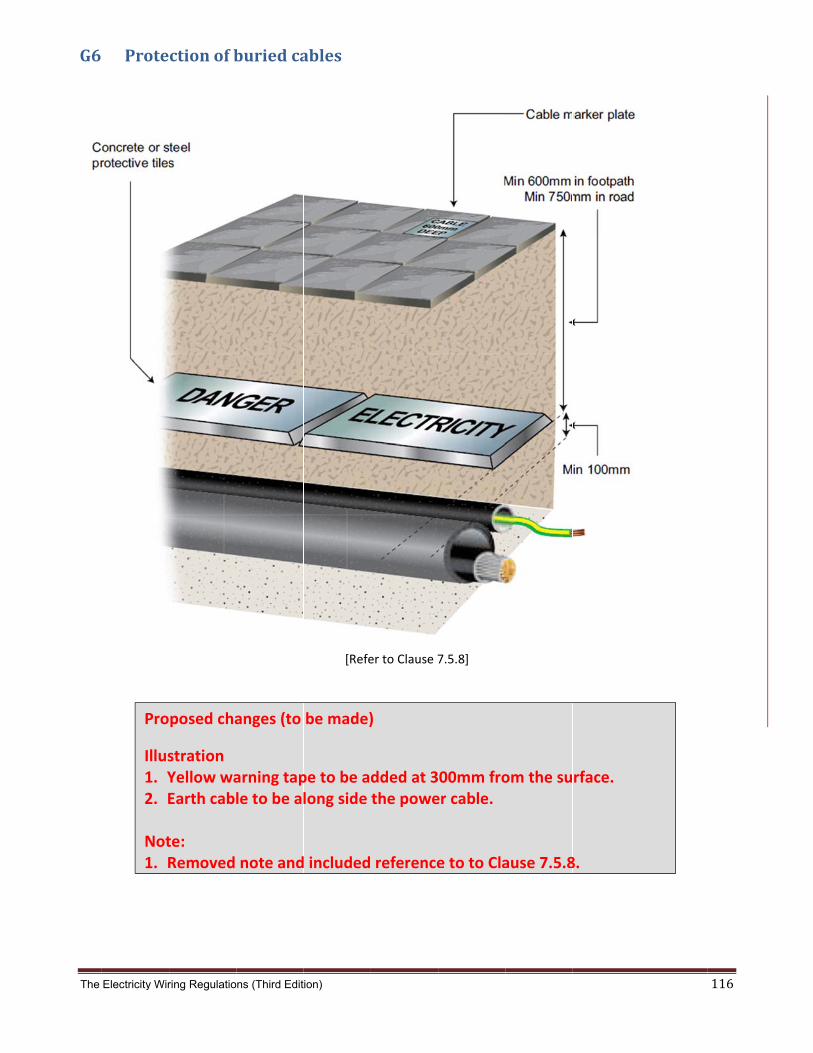
The
G6
Electricity Wir
Prote
Pro
Illus1. Y2. E Not1. R
ring Regulatio
ctionofb
posed cha
stration Yellow waEarth cabl
te: Removed
ns (Third Edit
buriedca
anges (to
arning taple to be al
note and
ion)
ables
[Refe
be made)
pe to be along side
d included
er to Clause 7
)
dded at 3the powe
reference
7.5.8]
00mm froer cable.
e to to Cla
om the su
ause 7.5.8
rface.
8.
116

The
G7
Electricity Wir
(a)
ring Regulatio
Exposed
ns (Third Edit
dunsheat
ion)
thedcabl
lesatter
minationnpoints
117
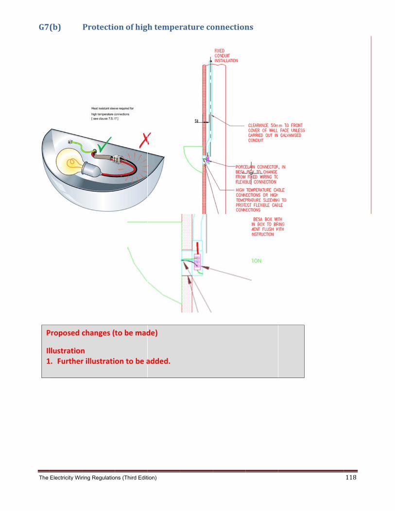
The
G7
P
Il1
Electricity Wir
(b)
Proposed c
llustration1. Further
ring Regulatio
Protectio
changes (
n r illustrati
ns (Third Edit
onofhig
to be mad
on to be a
ion)
htemper
de)
added.
ratureco
onnectionns
118

The
G7
[ se
Electricity Wir
(c)
ee clause 7
Propo
Illustr1. To
2. Fu
ring Regulatio
Weather
7.1.14, 9.4.
osed chan
ration o be amen
rther illus
ns (Third Edit
rprotecte
.1(b), 9.5.1
ges (to be
ded to inc
stration to
ion)
edoutdo
1(b), 9.6.2(
e made)
clude sock
o be show
oorsocke
(i) ]
ket‐outlet
wn for outd
et‐outlets
t as well.
door elect
s
trical installation.
119

The
G7
Electricity Wir
(d)
Pro
Illu1.
ring Regulatio
Earthtai
oposed ch
ustration Earth stu
ns (Third Edit
ilsinacce
hanges (to
d on switc
ion)
essories
o be made
ch to be a
andconn
e)
added.
nectionbboxes
120
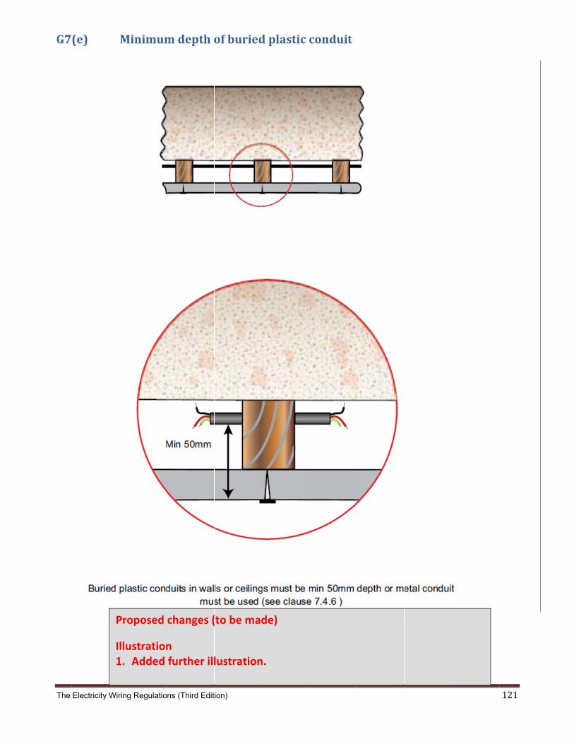
The
G7
Electricity Wir
(e)
P
I1
ring Regulatio
Minimum
Proposed
llustration1. Added
ns (Third Edit
mdeptho
changes (
n further ill
ion)
ofburied
(to be mad
lustration
dplasticc
de)
n.
conduit
121
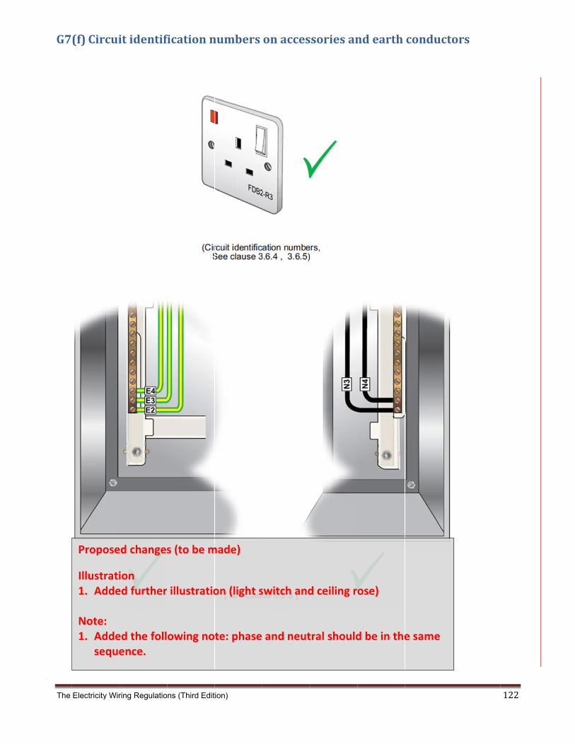
The
G7
Electricity Wir
(f)Circui
Propose
Illustrati1. Adde Note: 1. Adde
seque
ring Regulatio
itidentif
ed changes
ion ed further
ed the follence.
ns (Third Edit
ficationn
s (to be m
illustratio
owing no
ion)
numbers
made)
on (light s
te: phase
onacces
switch and
and neut
ssoriesan
d ceiling r
tral should
ndearth
ose)
d be in the
conducto
e same
ors
122
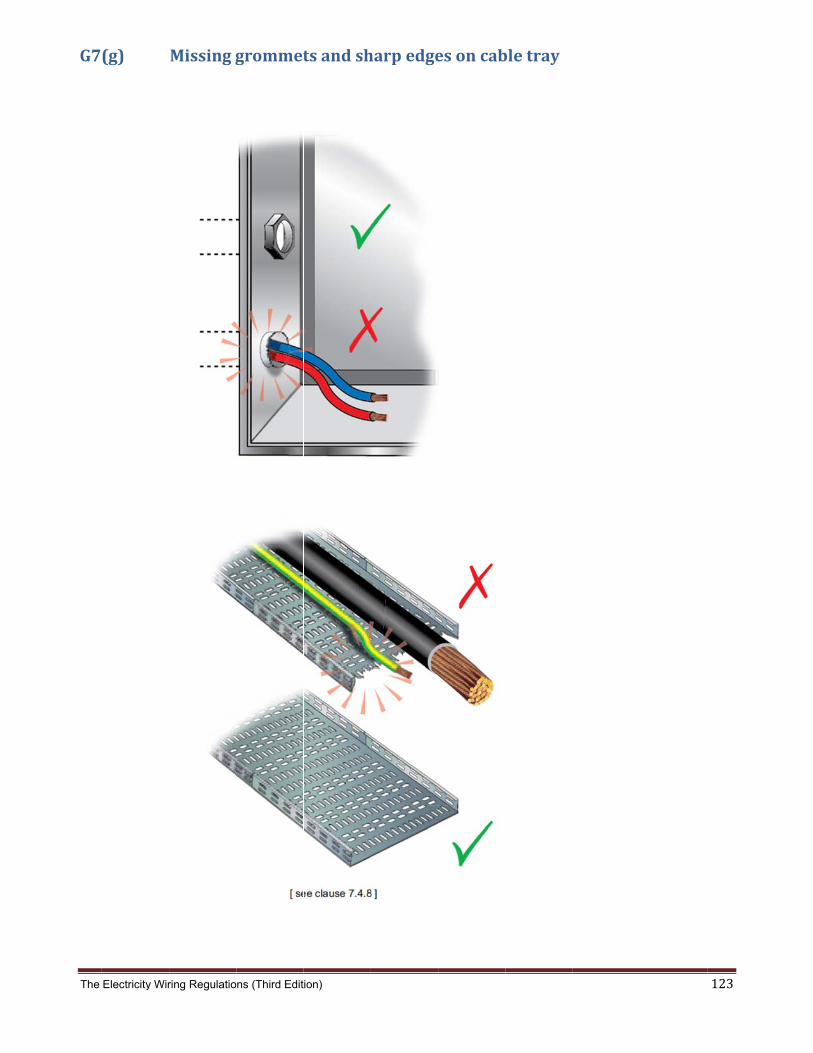
The
G7
Electricity Wir
(g)
ring Regulatio
Missingg
ns (Third Edit
grommet
ion)
tsandsh
harpedge
esoncabbletray
123
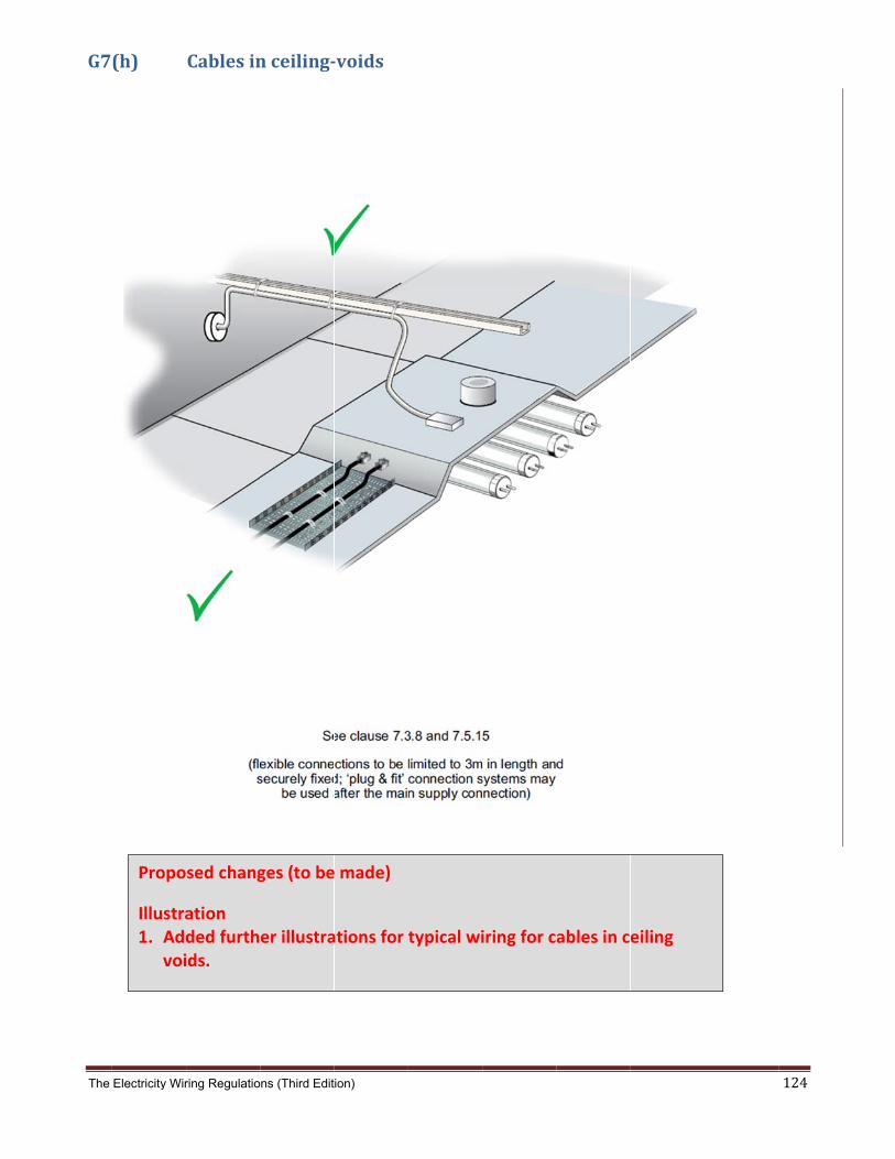
The
G7
Electricity Wir
(h)
Propo
Illustra1. Add
voi
ring Regulatio
Cablesin
sed chang
ation ded furthids.
ns (Third Edit
nceiling‐
ges (to be
er illustra
ion)
‐voids
e made)
ations for
typical wi
iring for cables in ceiling
124
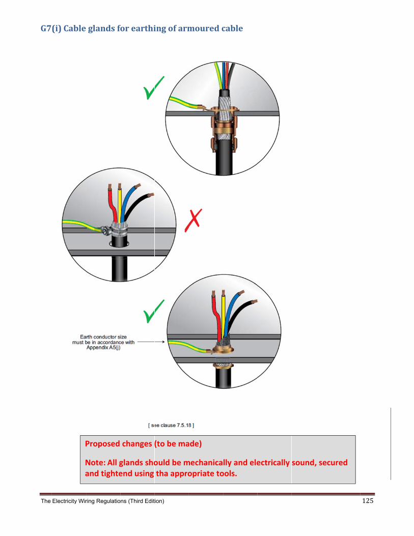
The
G7
Electricity Wir
(i)Cable
P
Na
ring Regulatio
glandsfo
Proposed
Note: All gand tighte
ns (Third Edit
forearthi
changes (
glands shoend using
ion)
ingofarm
(to be ma
ould be mtha appro
mouredc
ade)
mechanicaopriate to
cable
lly and eleools.
ectrically
sound, se
ecured
125

The
G7
Electricity Wir
(j)Earth
ring Regulatio
continui
ns (Third Edit
ityconne
ion)
ectionsa
crosscab
bletrayaandcondduit
126

The
G7
Electricity Wir
(k)
Propos
Illustra1. Add
ring Regulatio
Prohibit
sed chang
ation ded furthe
ns (Third Edit
tedtermi
ges (to be
er illustra
ion)
inalblock
made)
tion for a
ksandta
lighting c
apedconn
circuit.
nections
127

The
G7
Not
Electricity Wir
(l)Slottin
te: Single c possible used ar the pha
ring Regulatio
ngofstee
core cablee overheatround the case conduc
ns (Third Edit
elglandp
s in a steeting. This ccables (e.gctors.
ion)
platesfor
el enclosurecan be avog. brass or
[ see
rsinglec
e will causoided by en
aluminium
e clause 7.5
corecabl
e electromnsuring tha
m plate) or
5.11 ]
les
magnetic cuat a non ferslots are c
urrents in trromagnet
cut in the st
he steel anic materialteel betwe
128
nd is en

The
G7
Electricity Wir
(m)
ring Regulatio
Flex‐out
ns (Third Edit
lets
ion)
129

The
G8
Electricity Wir
. Typic
ring Regulatio
allightin
ns (Third Edit
ngcircuit
ion)
tinstallat
tions
130
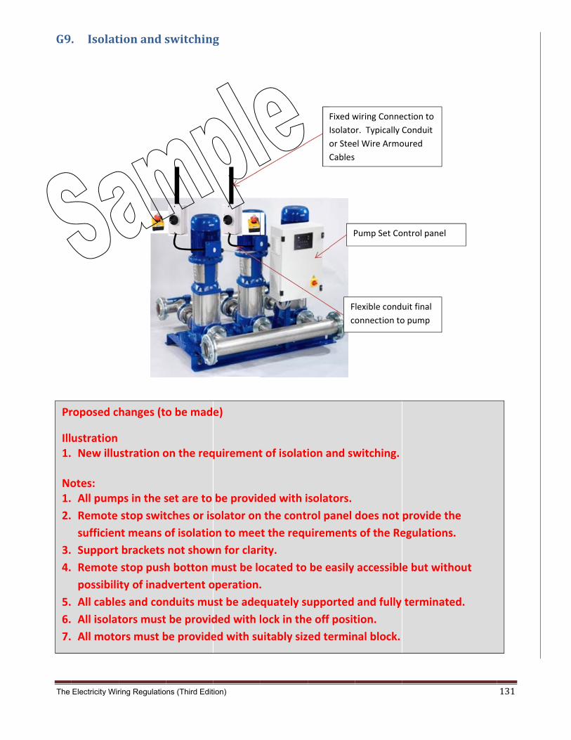
The
G9
Pr
Ill1. No1.
2.
3.
4.
5.
6.
7.
Electricity Wir
. Isolat
roposed c
ustration New illu
otes: All pump
Remote
sufficien
Support
Remote
possibili
All cable
All isolat
All moto
ring Regulatio
tionands
hanges (to
stration o
ps in the s
stop swit
nt means o
brackets
stop push
ty of inad
es and con
tors must
ors must b
ns (Third Edit
switching
o be mad
on the req
set are to
tches or is
of isolatio
not show
h botton m
dvertent o
nduits mu
be provid
be provide
ion)
g
e)
quirement
be provid
solator on
on to mee
wn for clar
must be lo
operation.
st be ade
ded with l
ed with su
t of isolati
ded with i
n the contr
t the requ
rity.
ocated to
.
quately su
lock in the
uitably siz
F
c
Fixed w
Isolato
or Stee
Cables
P
ion and sw
solators.
rol panel
uirements
be easily
upported
e off posit
ed termin
lexible cond
onnection to
wiring Conne
or. Typically
el Wire Armo
Pump Set Co
witching.
does not
s of the Re
accessibl
and fully
tion.
nal block.
uit final
o pump
ection to
Conduit
oured
ontrol panel
provide th
egulations
e but with
terminat
he
s.
hout
ed.
131

The
G1TheRegpub
C
Electricity Wir
0. Change following gulations, pblication.
Clause
A summ
will be a
ring Regulatio
gesinthetable lists tublished by
Sub
mary list o
added in t
ns (Third Edit
eThirdEthe clausesy the Burea
bject
of all the c
this sectio
ion)
Edition(Js that wereau in Janua
Reas
changes on
on.
Jan2014 changed ury 2014. T
son for change
n this edit
4)under the T
These are in
e
tion of the
Thrid Editiondicated by
e Electrici
on of the Ey a red line
ty Wiring
lectricity Wthroughout
Regulatio
132
Wiring t this
ons

The Electricity Wiring Regulations (Third Edition) 133
Notes

Electricity Wiring Regulations (Third Edition) – Public Consultation
Author Document Version Publication date Approved by
MY/CKL CD/R01/102 01 03 December 2013 MP Page 6 of 18
Consultation Annex B – Proposed changes Summary of proposed key changes to The Electricity Wiring Regulations 2007 (Revision 1, January 2009):
A.1 The scope of the Regulations now includes all Electrical Installations in the Emirate of Abu Dhabi, including Premises not connected to the Distribution Companies’ networks (for e.g. off-grid worker camps running on their own generators).
A.2 Clarification of the purpose of these Regulations which is to address the requirements for LV Electrical Installations only. The requirements for HV installations are addressed in the Electricity Distribution Code and the relevant Distribution Companies’ standards/specifications.
A.3 Clarify that even though the Distribution Company provides the design approval, it does not relieve the Owner and associated Licensed Contractor from its obligation to fully comply with these Regulations.
A.4 A new clause is added to enable Owners of major developments to enter into an undertaking with the Distribution Company to self-certify the design of their Electrical Installations. In such cases, there will be no requirement for the design to be approved by the Distribution Company before commencement of construction.
A.5 Enhancement of the requirements for the protection of electric shock from indirect contact by requiring the use of both the Earth Leakage Protected System (ELPS) and the Earth Equipotential Bonded System (EEBS).
A.6 New sections introduced to address External Lighting in Premises, Electrical Installations in Marinas or similar locations and solar PV systems.
A.7 Clarification that air conditioning units, motors, large electrical machines, fluorescent or discharge lighting, etc, shall be provided with integral power factor correction.
A.8 A new clause is added to prohibit the use of capacitor banks in residential villas.
A.9 Update of Guidance Notes G2 on the estimation of Connected Load and the use of diversity factors for final circuits, SMDBs and MDBs.
A.10 Enhancement of the contents of the Appendices and Guidance Notes to provide improved clarity.
The following table lists the clauses that were changed under the proposed Electricity Wiring Regulations (Edition 3). Notes:
(a) The Clause references in the table below refer to the proposed Electricity Wiring Regulations (Third Edition). There are some consequential changes in the numberings from the previous Electricity Wiring Regulations 2007 (Revision 1) following additions of new Regulations and Clauses.
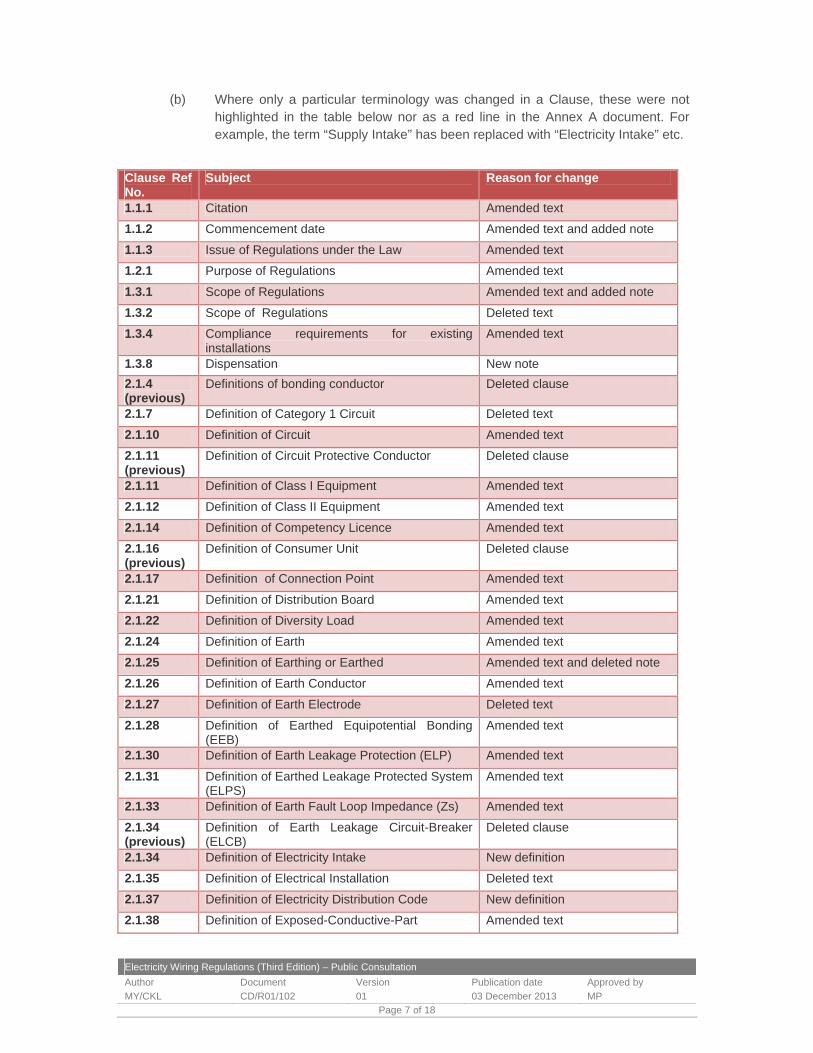
Electricity Wiring Regulations (Third Edition) – Public Consultation
Author Document Version Publication date Approved by
MY/CKL CD/R01/102 01 03 December 2013 MP Page 7 of 18
(b) Where only a particular terminology was changed in a Clause, these were not highlighted in the table below nor as a red line in the Annex A document. For example, the term “Supply Intake” has been replaced with “Electricity Intake” etc.
Clause Ref No.
Subject Reason for change
1.1.1 Citation Amended text
1.1.2 Commencement date Amended text and added note
1.1.3 Issue of Regulations under the Law Amended text
1.2.1 Purpose of Regulations Amended text
1.3.1 Scope of Regulations Amended text and added note
1.3.2 Scope of Regulations Deleted text
1.3.4 Compliance requirements for existing installations
Amended text
1.3.8 Dispensation New note
2.1.4 (previous)
Definitions of bonding conductor Deleted clause
2.1.7 Definition of Category 1 Circuit Deleted text
2.1.10 Definition of Circuit Amended text
2.1.11 (previous)
Definition of Circuit Protective Conductor Deleted clause
2.1.11 Definition of Class I Equipment Amended text
2.1.12 Definition of Class II Equipment Amended text
2.1.14 Definition of Competency Licence Amended text
2.1.16 (previous)
Definition of Consumer Unit Deleted clause
2.1.17 Definition of Connection Point Amended text
2.1.21 Definition of Distribution Board Amended text
2.1.22 Definition of Diversity Load Amended text
2.1.24 Definition of Earth Amended text
2.1.25 Definition of Earthing or Earthed Amended text and deleted note
2.1.26 Definition of Earth Conductor Amended text
2.1.27 Definition of Earth Electrode Deleted text
2.1.28 Definition of Earthed Equipotential Bonding (EEB)
Amended text
2.1.30 Definition of Earth Leakage Protection (ELP) Amended text
2.1.31 Definition of Earthed Leakage Protected System (ELPS)
Amended text
2.1.33 Definition of Earth Fault Loop Impedance (Zs) Amended text
2.1.34 (previous)
Definition of Earth Leakage Circuit-Breaker (ELCB)
Deleted clause
2.1.34 Definition of Electricity Intake New definition
2.1.35 Definition of Electrical Installation Deleted text
2.1.37 Definition of Electricity Distribution Code New definition
2.1.38 Definition of Exposed-Conductive-Part Amended text

Electricity Wiring Regulations (Third Edition) – Public Consultation
Author Document Version Publication date Approved by
MY/CKL CD/R01/102 01 03 December 2013 MP Page 8 of 18
Clause Ref No.
Subject Reason for change
2.1.39 Definition of Extraneous-Conductive-Part Amended text
2.1.44 Definition of indirect Contact Amended text
2.1.47 (previous)
Definition of Installation Deleted clause
2.1.45 Definition of Law Deleted text
2.1.46 Definition of Licensed Contractor Added text
2.1.50 Main Earth Terminal (MET) Amended text
2.1.51 Definition of Marina New definition
2.1.52 Definition of Owner Amended text and deleted note
2.1.53 Definition of Premises Added text
2.1.54 Definition of Prospective Fault Current Amended text
2.1.57 (previous)
Definition of Protective Conductor deleted clause
2.1.55 Definition of Protective Device deleted text
2.1.56 Definition of PV Solar photovoltaic New definition
2.1.60 Definition of Sub Main Distribution Board Added text
2.1.63 (previous)
Definition of Supply Intake Deleted clause
2.1.64 (previous)
Definition of Spur Circuit Deleted clause
2.1.61 Definition of Touch Voltage Amended text
3.1.1 Reference to BS 7671 Amended text
3.1.5 Distribution company issued specification Added text
3.2.1 Approval of Electrical Installations Amended text
3.2.2 Approval of Electrical Installations Deleted text and added a note
3.2.3 Self-certification of Electrical Installation New clause
3.2.4 Responsibility of Owner and associated Licensed Contractors.
New clause
3.2.5 Inspection and testing of new Electrical Installation
Amended text
3.2.6 Evidence of compliance against relevant standards
Amended text
3.2.7 Submission of load estimates Amended text
3.3.3 Repairs to existing Electrical Installations Amended text
3.4.1 Assessment of Licensed Contractors Deleted text
3.5.1 Requirements for safety Amended text
3.5.4 Requirements for safety Deleted text and added note
3.5.5 Requirements for safety Amended text
3.5.6 Requirement for safety Deleted text
3.5.10 Risk of fire due to electrical faults Amended text
3.5.12 Requirement for safety New clause
3.6.1 Labelling and identification requirements Amended text and note

Electricity Wiring Regulations (Third Edition) – Public Consultation
Author Document Version Publication date Approved by
MY/CKL CD/R01/102 01 03 December 2013 MP Page 9 of 18
Clause Ref No.
Subject Reason for change
3.6.2 Labelling requirements Amended text
3.6.6 Load distribution schedule and wiring diagrams Amended text
3.7.1 Environmental conditions in coastal areas Added text
Ch. 4 Electricity parameters and Electricity Intake Amended title
4.1 Electricity parameters Amended text
4.1.1 Electricity parameters Amended text
4.1.2 Electricity parameters - voltage and frequency Amended text and deleted note
4.1.3 Electricity parameters - voltage Amended text
4.1.4 Electricity parameters - frequency Amended text
4.1.5 (previous)
Electricity parameters - voltage and frequency Deleted clause
4.1.6 (previous)
Permissible variation in the supply frequency Deleted clause
4.1.5 Disturbances in the electricity supply voltage Amended text
4.1.6 Limits of disturbances in the electricity supply voltage
Amended text
4.1.7 Power factor requirement Amended text
4.1.8 Prospective fault current Added text
4.1.11 (previous)
Prospective fault current for HV supplies Deleted clause
4.2 Electricity Intake Amended text
4.2.1 Electricity Intake construction Added text and added note
4.2.2 Electricity intake Amended text
4.2.3 Electricity Intake access Amended text
4.2.4 Electricity Intake location Amended text
4.2.5 Equipment at the Electricity Intake Amended text
4.2.6 Electricity Intake room Amended text
4.2.7 Electricity Intake location Amended text
4.2.8 Electricity Intake ventilation Amended text and added note
4.2.9 Electricity Intake emergency lighting Amended text
4.2.10 Electricity Intake doors Amended text
4.2.11 Electricity Intake location Amended text
4.2.12 Electricity Intake doors Amended text
4.2.13 Electricity Intake layouts Amended text
4.2.14 Electricity Intake LV switchboards Amended text
4.2.15 HV/LV substation requirements Amended text
4.3 Connection point Amended text
4.3.1 (previous)
Customer Connection Point Deleted clause
4.3.1 Connection point Amended text
4.3.2 Connection point Amended text

Electricity Wiring Regulations (Third Edition) – Public Consultation
Author Document Version Publication date Approved by
MY/CKL CD/R01/102 01 03 December 2013 MP Page 10 of 18
Clause Ref No.
Subject Reason for change
4.4.1 Multiple occupancy premises Amended text
4.4.2 Multiple occupancy premises Amended text
5.1.1 General principles Added text
5.2.1 Overload and short circuit protection Added text
5.2.2 Main circuit breaker at the Connection Point Deleted text
5.2.3 Overload and short circuit protection Deleted text
5.2.5 Protection against overload Amended note
5.2.6 Prospective Fault Current Added text
5.2.7 Prospective Fault Current Amended text
5.3.2 Reference to BS EN Updated
5.3.4 Requirements for ELP and EBB Amended text
5.3.5 Requirements for ELP Deleted clause
5.4.1 ELPS "back up" Amended text
5.4.2 Older types of ELCB devices Deleted note
5.4.3 Reference to BS EN Updated and added a note
5.4.5 Earth leakage protective devices discrimination Amended text
5.4.7 (previous)
ELP and EEB requirements Deleted clause
5.4.7 RCD labelling requirements Amended text
5.4.8 RCD rating for final circuits Amended text
5.4.9 ELP for special circuits Amended text and added note
5.4.13 (previous)
Earth leakage alarm Deleted clause
5.5.2 Limit on the duration of an earth fault Amended text
5.5.3 Earth fault loop impedance added text
5.5.8 Equipotential Bonding connections Added text
5.5.11 Reference to BS Added text
5.6.1 Isolation requirements Deleted note
5.6.2 Sectioning requirements Amended text
5.6.3 Isolation requirements for mechanical equipment
New clause
5.6.5 Isolation requirements for socket outlets and flex outlets
Amended text
5.6.6 Emergency switching Amended text
5.7.5 Insulation resistance test Added text
6.2.1 Systems of earthing Amended text
6.2.2 TN-S and TT earthing systems Amended text
6.2.3 Neutral and Earth Conductors Clarification
6.3.1 Main earth terminal Clarification
6.3.2 Main earth terminal New clause
6.3.3 Removable link at MET Clarification
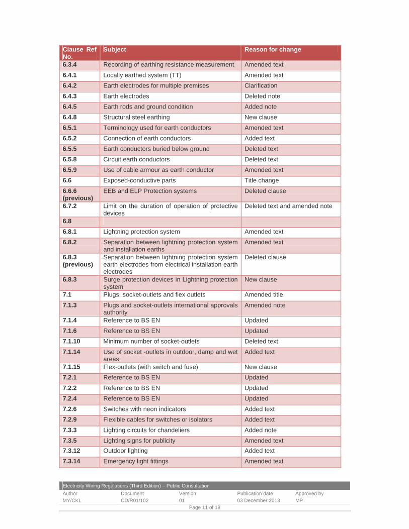
Electricity Wiring Regulations (Third Edition) – Public Consultation
Author Document Version Publication date Approved by
MY/CKL CD/R01/102 01 03 December 2013 MP Page 11 of 18
Clause Ref No.
Subject Reason for change
6.3.4 Recording of earthing resistance measurement Amended text
6.4.1 Locally earthed system (TT) Amended text
6.4.2 Earth electrodes for multiple premises Clarification
6.4.3 Earth electrodes Deleted note
6.4.5 Earth rods and ground condition Added note
6.4.8 Structural steel earthing New clause
6.5.1 Terminology used for earth conductors Amended text
6.5.2 Connection of earth conductors Added text
6.5.5 Earth conductors buried below ground Deleted text
6.5.8 Circuit earth conductors Deleted text
6.5.9 Use of cable armour as earth conductor Amended text
6.6 Exposed-conductive parts Title change
6.6.6 (previous)
EEB and ELP Protection systems Deleted clause
6.7.2 Limit on the duration of operation of protective devices
Deleted text and amended note
6.8
6.8.1 Lightning protection system Amended text
6.8.2 Separation between lightning protection system and installation earths
Amended text
6.8.3 (previous)
Separation between lightning protection system earth electrodes from electrical installation earth electrodes
Deleted clause
6.8.3 Surge protection devices in Lightning protection system
New clause
7.1 Plugs, socket-outlets and flex outlets Amended title
7.1.3 Plugs and socket-outlets international approvals authority
Amended note
7.1.4 Reference to BS EN Updated
7.1.6 Reference to BS EN Updated
7.1.10 Minimum number of socket-outlets Deleted text
7.1.14 Use of socket -outlets in outdoor, damp and wet areas
Added text
7.1.15 Flex-outlets (with switch and fuse) New clause
7.2.1 Reference to BS EN Updated
7.2.2 Reference to BS EN Updated
7.2.4 Reference to BS EN Updated
7.2.6 Switches with neon indicators Added text
7.2.9 Flexible cables for switches or isolators Added text
7.3.3 Lighting circuits for chandeliers Added note
7.3.5 Lighting signs for publicity Amended text
7.3.12 Outdoor lighting Added text
7.3.14 Emergency light fittings Amended text
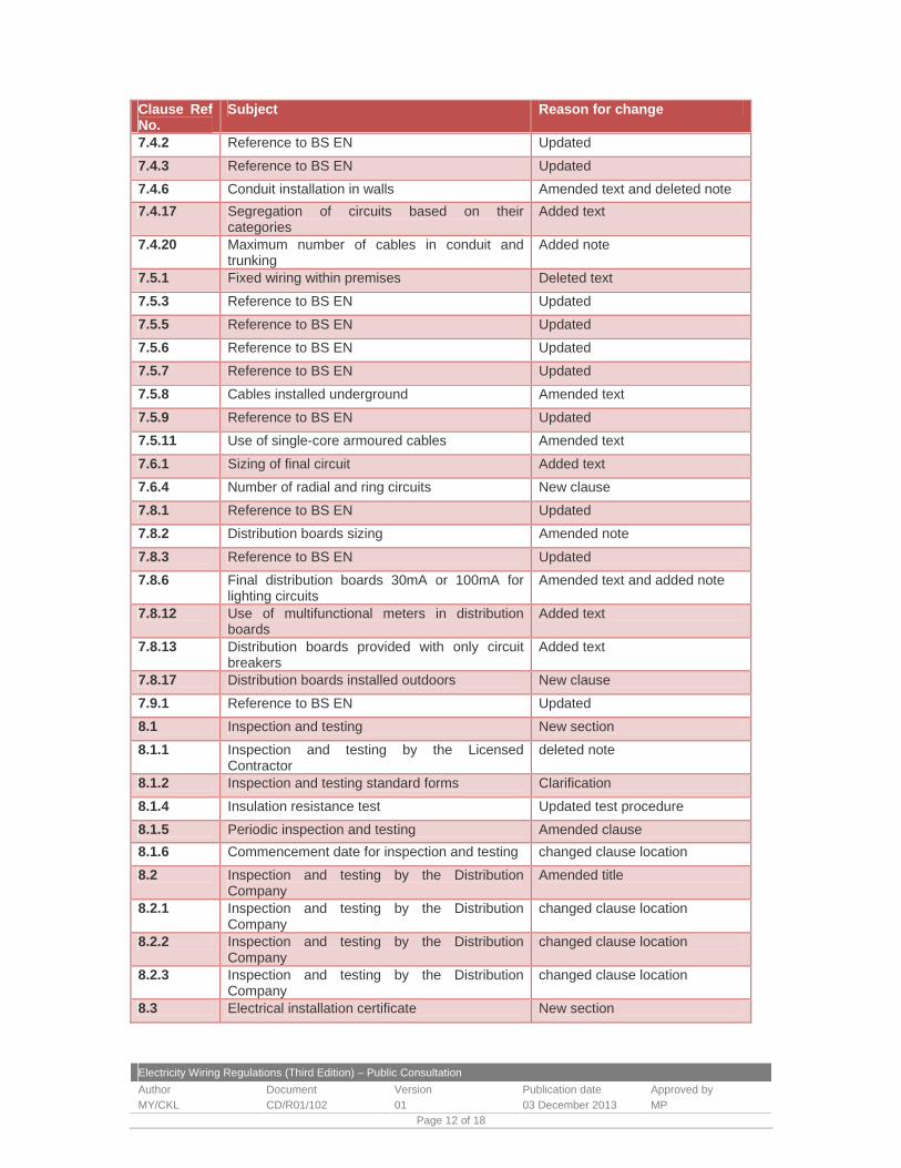
Electricity Wiring Regulations (Third Edition) – Public Consultation
Author Document Version Publication date Approved by
MY/CKL CD/R01/102 01 03 December 2013 MP Page 12 of 18
Clause Ref No.
Subject Reason for change
7.4.2 Reference to BS EN Updated
7.4.3 Reference to BS EN Updated
7.4.6 Conduit installation in walls Amended text and deleted note
7.4.17 Segregation of circuits based on their categories
Added text
7.4.20 Maximum number of cables in conduit and trunking
Added note
7.5.1 Fixed wiring within premises Deleted text
7.5.3 Reference to BS EN Updated
7.5.5 Reference to BS EN Updated
7.5.6 Reference to BS EN Updated
7.5.7 Reference to BS EN Updated
7.5.8 Cables installed underground Amended text
7.5.9 Reference to BS EN Updated
7.5.11 Use of single-core armoured cables Amended text
7.6.1 Sizing of final circuit Added text
7.6.4 Number of radial and ring circuits New clause
7.8.1 Reference to BS EN Updated
7.8.2 Distribution boards sizing Amended note
7.8.3 Reference to BS EN Updated
7.8.6 Final distribution boards 30mA or 100mA for lighting circuits
Amended text and added note
7.8.12 Use of multifunctional meters in distribution boards
Added text
7.8.13 Distribution boards provided with only circuit breakers
Added text
7.8.17 Distribution boards installed outdoors New clause
7.9.1 Reference to BS EN Updated
8.1 Inspection and testing New section
8.1.1 Inspection and testing by the Licensed Contractor
deleted note
8.1.2 Inspection and testing standard forms Clarification
8.1.4 Insulation resistance test Updated test procedure
8.1.5 Periodic inspection and testing Amended clause
8.1.6 Commencement date for inspection and testing changed clause location
8.2 Inspection and testing by the Distribution Company
Amended title
8.2.1 Inspection and testing by the Distribution Company
changed clause location
8.2.2 Inspection and testing by the Distribution Company
changed clause location
8.2.3 Inspection and testing by the Distribution Company
changed clause location
8.3 Electrical installation certificate New section

Electricity Wiring Regulations (Third Edition) – Public Consultation
Author Document Version Publication date Approved by
MY/CKL CD/R01/102 01 03 December 2013 MP Page 13 of 18
Clause Ref No.
Subject Reason for change
8.3.1 Licensed contractor requirements New clause
8.3.2 Electrical installation certificate changed clause location and added text
8.3.3 Extension or alterations to an electrical installation
changed clause location
9.3.2 Principal requirements for bathrooms and similar locations
Amended text
9.3.3 Requirement for earth leakage protective system and earth equipotential bonding system
Amended text
9.4.1 Reference to BS EN and IP rating Updated
9.4.2 Requirement for earth leakage protective system and earth equipotential bonding system
Amended text
9.5.1 Reference to BS EN Updated
9.5.2 Requirement for earth leakage protective system and earth equipotential bonding system
Amended text
9.6 Temporary electrical installation updated title
9.6.1 Temporary electrical installation scope Amended clause
9.6.2 design and construction requirement of temporary electrical installations
Amended clause
9.6.3 Reduced low voltage requirements in temporary electrical installations
Amended text
9.7.1 specification for street lighting Deleted clause
9.7.2 Requirements for ELP and EBB Amended text
9.8 External lighting New section and clauses
9.9 Marinas and similar locations New section and clauses
9.10 Solar photovoltaic PV systems New section and clauses
Ch. 10 Power factor correction Updated title
10.1.1 Power factor requirement Deleted text
10.1.2 Integral power factor correction requirements Changed clause location
10.1.3 Capacitor banks in villas New clause
10.1.6 Capacitor banks Amended clause
10.1.7 Capacitor banks design requirements New clause
10.1.8 Induction motors with permanently connected capacitor unit
Clarification
10.1.9 Harmonic filter reactors added text
10.2.1 Specifications for capacitors New clause
10.2.2 Specifications for capacitors New clause
10.2.3 Specifications for capacitors New clause
10.2.4 Specifications for capacitors Changed clause location
10.2.5 Specifications for capacitors Added note
10.2.6 Nameplates Changed clause location
10.2.7 Harmonic withstand Correction
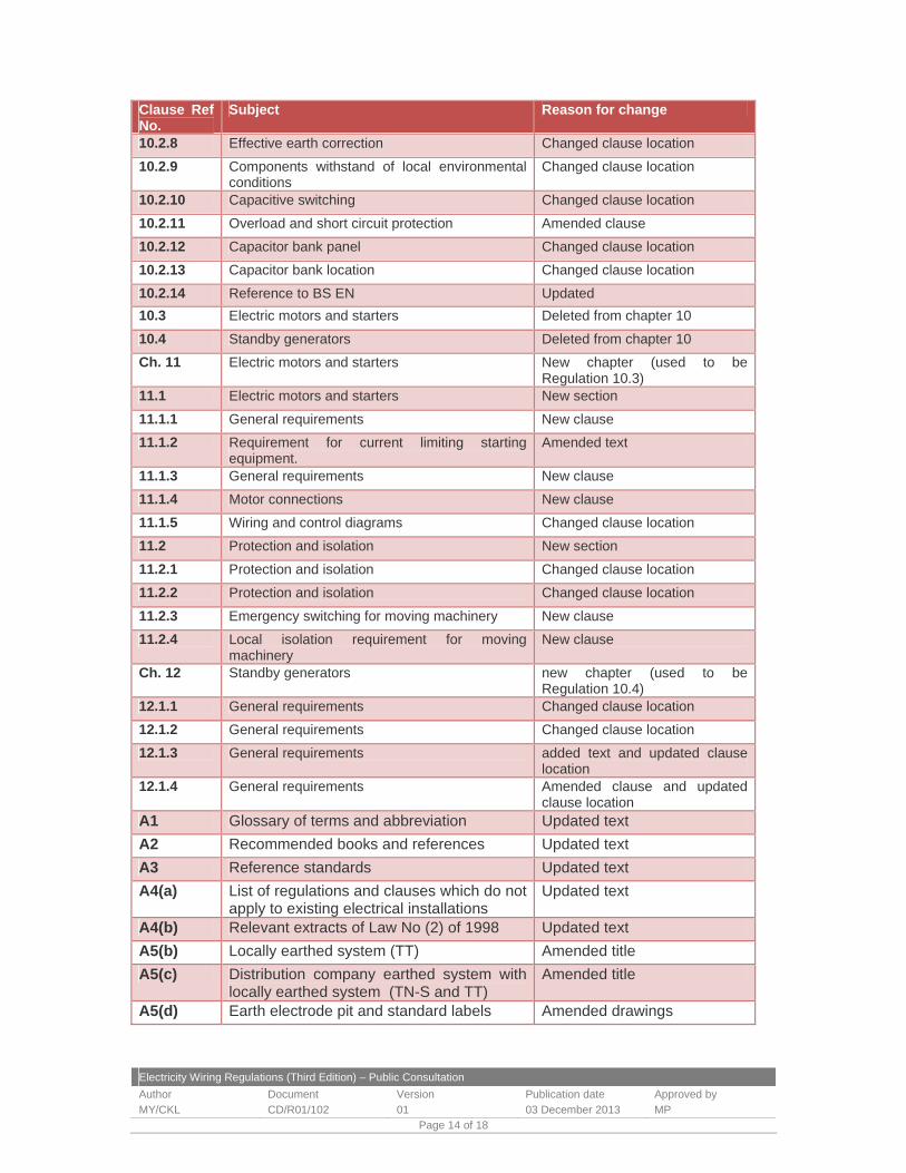
Electricity Wiring Regulations (Third Edition) – Public Consultation
Author Document Version Publication date Approved by
MY/CKL CD/R01/102 01 03 December 2013 MP Page 14 of 18
Clause Ref No.
Subject Reason for change
10.2.8 Effective earth correction Changed clause location
10.2.9 Components withstand of local environmental conditions
Changed clause location
10.2.10 Capacitive switching Changed clause location
10.2.11 Overload and short circuit protection Amended clause
10.2.12 Capacitor bank panel Changed clause location
10.2.13 Capacitor bank location Changed clause location
10.2.14 Reference to BS EN Updated
10.3 Electric motors and starters Deleted from chapter 10
10.4 Standby generators Deleted from chapter 10
Ch. 11 Electric motors and starters New chapter (used to be Regulation 10.3)
11.1 Electric motors and starters New section
11.1.1 General requirements New clause
11.1.2 Requirement for current limiting starting equipment.
Amended text
11.1.3 General requirements New clause
11.1.4 Motor connections New clause
11.1.5 Wiring and control diagrams Changed clause location
11.2 Protection and isolation New section
11.2.1 Protection and isolation Changed clause location
11.2.2 Protection and isolation Changed clause location
11.2.3 Emergency switching for moving machinery New clause
11.2.4 Local isolation requirement for moving machinery
New clause
Ch. 12 Standby generators new chapter (used to be Regulation 10.4)
12.1.1 General requirements Changed clause location
12.1.2 General requirements Changed clause location
12.1.3 General requirements added text and updated clause location
12.1.4 General requirements Amended clause and updated clause location
A1 Glossary of terms and abbreviation Updated text
A2 Recommended books and references Updated text
A3 Reference standards Updated text
A4(a) List of regulations and clauses which do not apply to existing electrical installations
Updated text
A4(b) Relevant extracts of Law No (2) of 1998 Updated text
A5(b) Locally earthed system (TT) Amended title
A5(c) Distribution company earthed system with locally earthed system (TN-S and TT)
Amended title
A5(d) Earth electrode pit and standard labels Amended drawings

Electricity Wiring Regulations (Third Edition) – Public Consultation
Author Document Version Publication date Approved by
MY/CKL CD/R01/102 01 03 December 2013 MP Page 15 of 18
Clause Ref No.
Subject Reason for change
A5(e) Main earth terminal (MET) at main distribution board (MDB)
Amended drawings
A5(f) Main earth conductors (MEC) and circuit earth conductors (CEC)
Amended drawings and added notes
A5(g) Components of earth fault loop impedance Amended text and added note
A5(h) Earth fault loop impedance values required for MCBs (at 230 V)
Updated table values and reference
A5(i) Resistance per metre of copper conductors Updated title
A5(j) Sizing of earth conductors and equipotential bonding conductors
Correct text and update table reference
A5(k) Minimum number of earth electrodes Updated note 2
A5(l) Mandatory connections to earth conductors Updated and added text
A5(m) Residual operating current settings for RCDs and ELP devices
Added text and updated cooker settings
A6(b) Time-current characteristic of Type B MCBs Updated figure
A6(c) Time-current characteristic of Type C MCBs
Updated figure
A6(d) Time-current characteristic of Type D MCBs
Updated figure
A6(e) Typical energy let-through characteristics of MCBs
Updated figure
A6(f) MCBs selection criteria Deleted text
A7(a) Circuit rating and voltage drop for PVC single core cables (non-armoured)
Updated title, table values and reference
A7(b) Circuit rating and voltage drop for PVC multi-core cables (non-armoured)
Updated title, table values and reference
A7(c) Circuit rating and voltage drop for PVC multi-core cables (armoured)
Updated title, table values and reference
A7(d) Circuit rating and voltage drop for thermo-setting (XLPE) multi-core cables (armoured)
Updated title, table values and reference
A7(e) Circuit rating for MICC cable Updated title, table values and reference
A7(f) Circuit rating and voltage drop for flexible cords
Updated title and reference
A7(g) Rating factors with respect to ambient air temperature
Update title and table values
A7(h) Rating factors with respect to grouping of cables
Update title and table values
A8 Colour identification for Solar PV d.c. cables
Updated table
A11 Standard wiring diagram symbols for fused connection unit and 16A industrial socket outlet
Added two more symbols
A12(a) Labelling of Electrical Installation Updated title and added more standard labels
A12(b) Minimum sizes of LV switch rooms Updated title and deleted

Electricity Wiring Regulations (Third Edition) – Public Consultation
Author Document Version Publication date Approved by
MY/CKL CD/R01/102 01 03 December 2013 MP Page 16 of 18
Clause Ref No.
Subject Reason for change
illustration
A12(c) Typical layout of final distribution board (FDB) and RCD label
Updated illustration
A12(d) Typical layout of LV switchroom Updated illustration
A13 Boundary of connection point and scope of the Regulations
Updated text
A14 Typical layout for small power and lighting circuits
Updated illustration
A15 Minimum number of socket-outlets and connection points
Amended minimum allowed number of socket-outlets and added text
A16 Mounting height for accessories and socket-outlets
Updated illustration
A17(b) Industrial plugs and socket-outlets Updated illustration
A17(c) Shaver socket-outlets for bathrooms Updated title and referenced standard
A18(b) Terminology change 'conductive' Amended text
A18(c) Reference to BS EN Updated
A19(a) Measurement of earth electrode resistance Updated test procedures
A19(b) Measurement of distribution company supply impedance (Ze)
Updated title
A19 (c) Measurement of total earth fault loop impedance (Zs)
Updated title and added note
A19(d) Circuit continuity, (R1+R2) and (R1+Rn) tests
Updated title and test procedures
A19(e) Lamp Holder circuit polarity tests Updated title
A19(f) Segregation and Insulation resistance tests Updated title and test procedures
A19(g) Sequence of testing for new installations - RCD test
Added text
A20(a) Electrical installation certificate Updated form
A20(b)(c) Inspection Report Updated form
A20(d) Installation testing report Updated report
A20(e) FDB, SMDB and MDB sample load schedules
Updated
A20(f) Solar PV test report New appendix
A20(g) Solar PV system inspection report New appendix
A21 General marinas connection arrangements New illustration
A22 General solar PV connection arrangements New illustration
G1 Guidance note on supply voltage change Amended text and illustration
G2 Estimation of connected load and diversity factors
Updated Guidance Notes
G3(a) Photograph of busbar riser Amended illustration
G3(b) Photograph of final distribution boards (horizontal DIN rail)
Amended title

Electricity Wiring Regulations (Third Edition) – Public Consultation
Author Document Version Publication date Approved by
MY/CKL CD/R01/102 01 03 December 2013 MP Page 17 of 18
Clause Ref No.
Subject Reason for change
G3(c) Photograph of final distribution board (vertical, split busbar type)
Amended illustration
G4(a) Direct contact with electricity No change
G4(c) Main and supplementary earthed equipotential bonding (EEB)
Amended text and illustration
G4(d) Illustration of earth leakage protected system (ELPS)
Amended text
G4(e) Grading of RCDs in an ELP system Amended note
G4(f) ELP system supplied from LV switchroom Updated illustration
G5(a) RCD operating characteristics and electric shock
Added text
G5(b) Typical values of body resistance and physiological effects
Typographical error
G5(d) Types of RCDs No change
G5(e) Sources of tripping of RCDs Amended title
G6 Protection of buried cables Amended note and illustration
G7(b) Protection of high temperature connections Amended illustration
G7(c) Weather protected outdoor socket-outlets Amended text and illustration
G7(d) Earth tails in accessories and connection boxes
Amended illustration
G7(e) Minimum depth of buried plastic conduit Added illustration
G7(f) Circuit identification numbers on accessories and earth conductors
Added note and illustration
G7(h) Cables in ceiling-voids Added illustration
G7(i) Cable glands for earthing of armoured cable
Added note
G7(k) Prohibited terminal blocks and taped connections
Added illustration
G7(l) Slotting of steel gland plates for single core cables
Added text to note
G7(m) Flex-outlets Amended illustration
G8 Typical lighting circuits installations New guidance
G9 Isolation and switching New guidance
G10 Third edition (Jan 2014) Updated

Electricity Wiring Regulations (Third Edition) – Public Consultation
Author Document Version Publication date Approved by
MY/CKL CD/R01/102 01 03 December 2013 MP Page 18 of 18
Consultation Annex C Bureau response template An Electronic copy of this response template can be obtained from the Bureau. Submission of comments on the Electricity Wiring Regulations (Third Edition) Comments From <Organisation / Contact Person> General Comments 1 2 3 4 5 Notes: insert more rows as required
Specific Comments on the Regulations Clause/Appendix/Guidance No. Comments and Rationale Proposed Change Notes: insert more rows as required