
FERROUS - rdso.indianrailways.gov.in
431
Transcript of FERROUS - rdso.indianrailways.gov.in
FERROUS AND NON FERROUS METALS USED
IN RAILWAYS,
BRIEF ON HEAT TREATMENT PROCESSES,
INDUCTION HEATING,
BRIEF ON METAL WEAR AND LUBRICATION,
PLAIN AND ROLLER BEARINGS — THEORY,
APPLICATION, SELECTION, MAINTENANCE
AND PRECAUTIONS,
LUBRICANTS SPECIFICATIONS, PROPERTIES
AND SELECTION,
RUBBER COMPONENTS SPECIFICATIONS AND
STORAGE,
ELECTROLYTIC COPPER

Element Iron, in pure form, hardly plays any role in
our life.
Great advances in modern civilization has taken place
due to discovery and use of mixtures (Alloys) of metal
iron and non metal carbon.
Mixture of metal iron & non metal carbon is melted
together and cast.
They have metallic properties & serve useful purpose.
The reasons of great utility of these iron carbon alloys
are:
• These alloys have wide variations in physical
properties, based upon their composition & heat
treatment.
• The cost of these alloys are low.
• Iron alloys have distinctive characters like
magnetism & allotropy.
Maximum Carbon that is available in any iron-carbon
system is less than 7%.
Any alloy containing less than 2.0% Carbon is called
“Steels” & the alloys, having Carbon% beyond this
range is called “Cast Iron” according to general
definition.
Commercial steels are not pure iron carbon alloys.
Certain elements in varying proportions remain present.
In many steels the presence of other elements is
incidental. The presence of amount of carbon plays the
vital role for determining the properties of the steel.
These steels are called “carbon steels”
There are certain steels consisting of Iron, Carbon &
greater % of other elements than are usually found in
Carbon steels.
The other elements are added for the purpose of
modifying the properties of steels & making them
different from those of carbon steels.
These steels are called “Alloyed steels”.
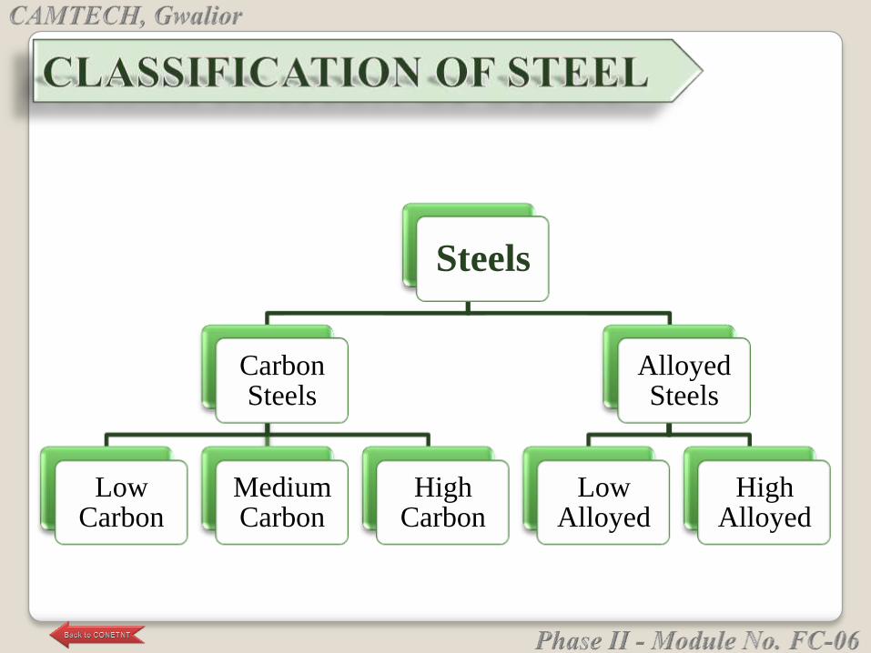
Steels
Carbon Steels
Low Carbon
Medium Carbon
High Carbon
Alloyed Steels
Low Alloyed
High Alloyed
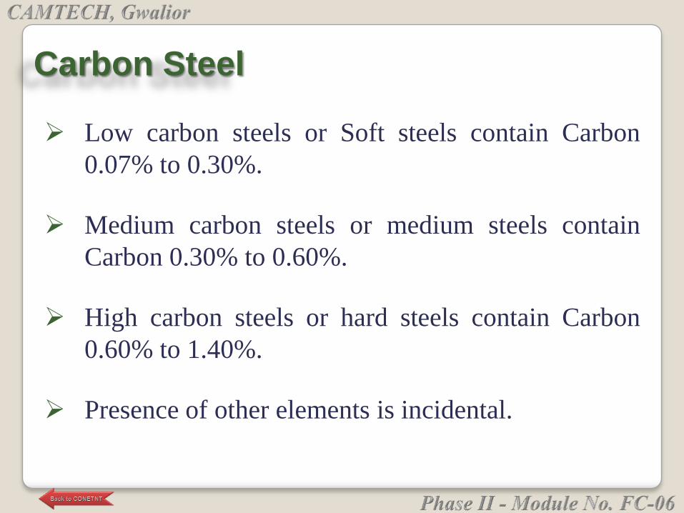
Low carbon steels or Soft steels contain Carbon
0.07% to 0.30%.
Medium carbon steels or medium steels contain
Carbon 0.30% to 0.60%.
High carbon steels or hard steels contain Carbon
0.60% to 1.40%.
Presence of other elements is incidental.
Carbon Steel
Majority of the alloyed steels contain less than 5% of
any element other than iron. These are called Low
alloyed steel.
Addition of the elements other than carbon modify the
properties of steel.
The addition of such elements to pure iron has no
significant effect.
Alloy Steel
Low Alloy Steel
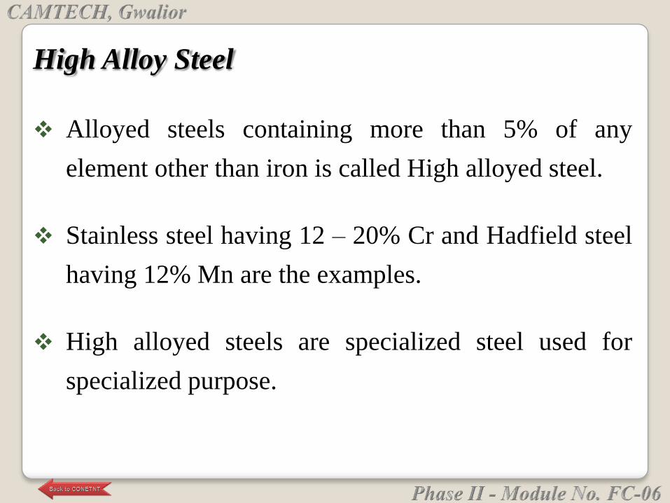
Alloyed steels containing more than 5% of any
element other than iron is called High alloyed steel.
Stainless steel having 12 – 20% Cr and Hadfield steel
having 12% Mn are the examples.
High alloyed steels are specialized steel used for
specialized purpose.
High Alloy Steel
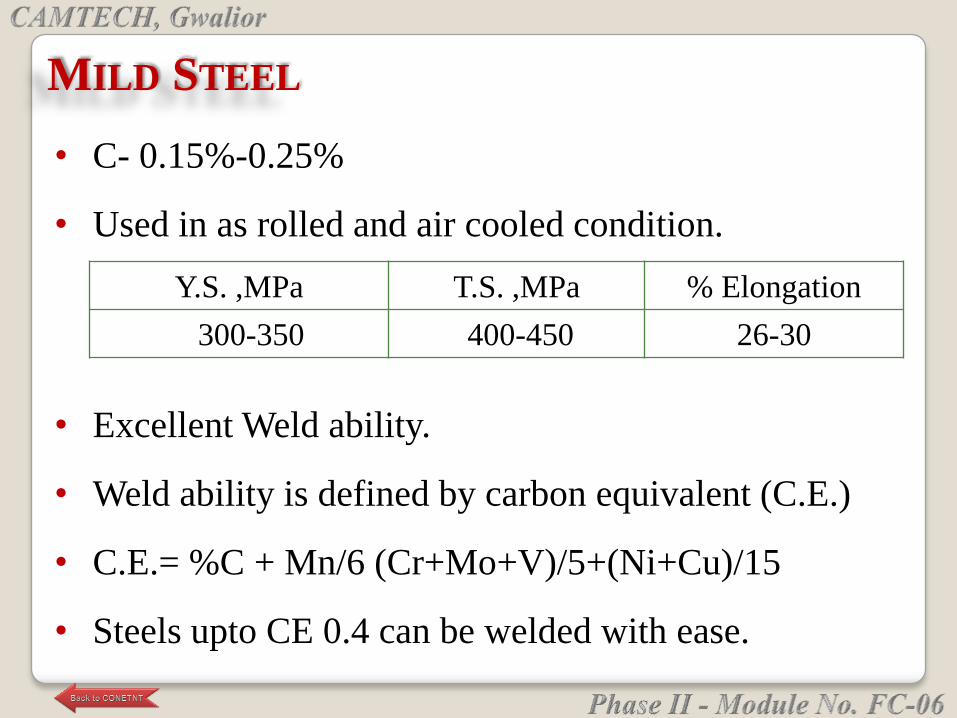
• C- 0.15%-0.25%
• Used in as rolled and air cooled condition.
Y.S. ,MPa T.S. ,MPa % Elongation
300-350 400-450 26-30
MILD STEEL
• Excellent Weld ability.
• Weld ability is defined by carbon equivalent (C.E.)
• C.E.= %C + Mn/6 (Cr+Mo+V)/5+(Ni+Cu)/15
• Steels upto CE 0.4 can be welded with ease.
• Structural Components
Plates for ship hulls
Boilers
I , H beams, angles channels, girders etc.
Application
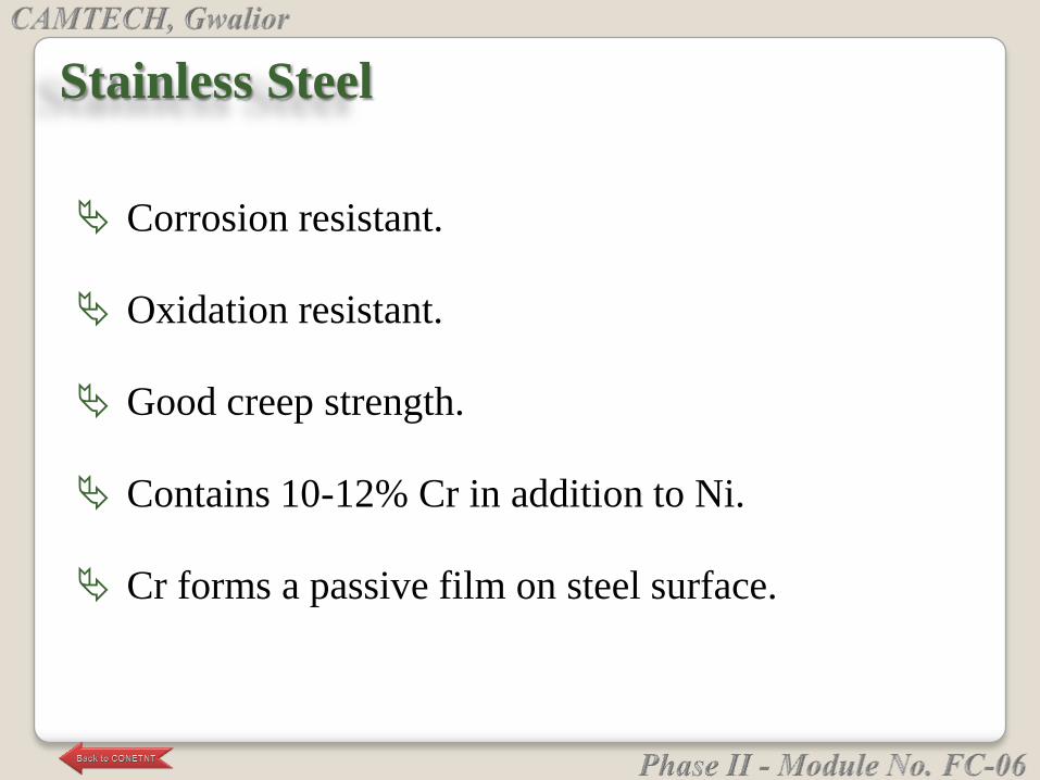
Corrosion resistant.
Oxidation resistant.
Good creep strength.
Contains 10-12% Cr in addition to Ni.
Cr forms a passive film on steel surface.
Stainless Steel
Nuclear plants.
Power generating units.
Pulp and paper manufacturing plants.
Food processing units.
Petrochemical industries.
Household items 18/8 formeability is excellent.
Surgical items.
Application
Low alloy steel with Cr.
C-1.0% , Mn-0.5%, Cr-1.3-1.5%
Due to presence of Cr, it has excellent hardenability.
Used for manufacture of steel balls and rollers for
ball and roller bearings.
Ball Bearing Steel

(OHNS)
Type of tool steel in which the hardening and
tempering does not produce any appreciable change
in size by proper control of tempering temperature.
Oil Hardening Non Shrinking Steel
• C-1.0% , Mn-1-1.5% , W-0.5% , Cr-0.8% , V-0.2%
• Used for vernier calipers, screw gauges , dial gauge
components.
High Carbon High Chromium Steel
Tool steel
Gives optimum wear resistance at room temperature.
C-1-1.3%C , cr-10-13%
Used for making
• Cold drawing dies
• Cold punching dies
• Cold forming tools
• Grinding media balls
Tool steel.
Used for high speed cutting
Tool tip becomes red hot
W or mo is added to provide red hardness
High Speed Steel
The capability of maintaining high hardness and a
keen cutting edge even upto the red hot temperature
of 600 ºc.
Red Hardness

Contains larger amount of V alongwith cobalt.
Cobalt extremely efficient in increasing red
hardness.
Longer tool life.
More severe cutting can be done.
V increases cutting efficiency by maintaining a very
fine cutting edge.
Ultra High Speed Steel
Alloy steel containing SI.
Reduces hysteresis losses and eddy current losses
due to high resistivity.
Used in
- armature of motors
- generator
- transformer cores.
Magnetic Steel
Posses high elastic limit.
High resilience.
Enough toughness.
Cr-W or Cr-Mo steels are used.
Spring Steel
High resistance to oxidation and scaling.
High creep strength to retain good strength at the
temperature of application.
Structural stability.
Contain high amount of Cr (20-33%).
Besides that V, W, Mo are also added to improve
creep resistance.
Heat Resisting Steel
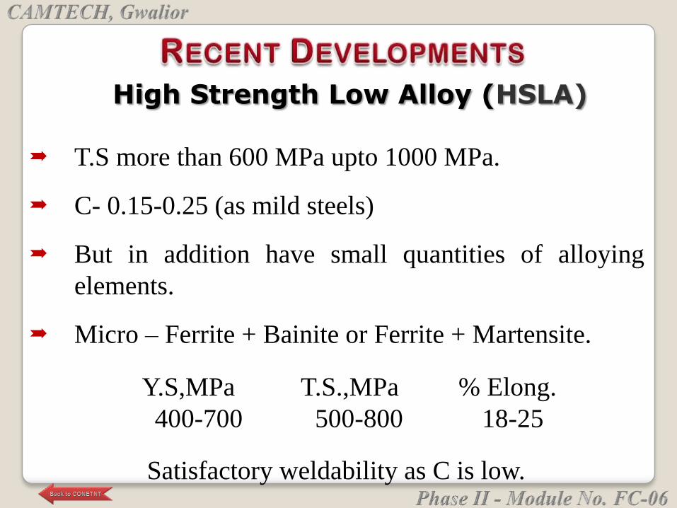
T.S more than 600 MPa upto 1000 MPa.
C- 0.15-0.25 (as mild steels)
But in addition have small quantities of alloying
elements.
Micro – Ferrite + Bainite or Ferrite + Martensite.
Y.S,MPa T.S.,MPa % Elong.
400-700 500-800 18-25
Satisfactory weldability as C is low.
High Strength Low Alloy (HSLA)

In mild steel small amounts of strong carbide forming
elements such as Niobium , Vanadium and Titanium are
added.
The total concentration of the microalloying elements is
than 0.2%.
Very fine ferrite grain size.ASTM 12-14.
Fine dispersion of alloy carbides results in precipitation
hardening.
Y.S,MPa T.S.,MPa % Elong.
400-500 600-650 20-22
Lower Elong. & poor formability.
Micro-alloyed Steel
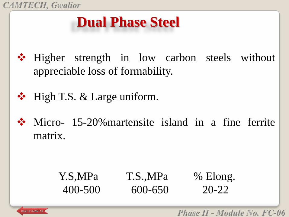
Higher strength in low carbon steels without
appreciable loss of formability.
High T.S. & Large uniform.
Micro- 15-20%martensite island in a fine ferrite
matrix.
Y.S,MPa T.S.,MPa % Elong.
400-500 600-650 20-22
Dual Phase Steel
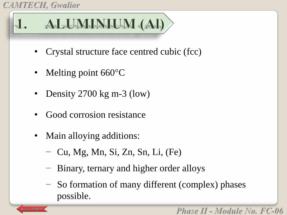
• Crystal structure face centred cubic (fcc)
• Melting point 660°C
• Density 2700 kg m-3 (low)
• Good corrosion resistance
• Main alloying additions:
− Cu, Mg, Mn, Si, Zn, Sn, Li, (Fe)
− Binary, ternary and higher order alloys
− So formation of many different (complex) phases
possible.
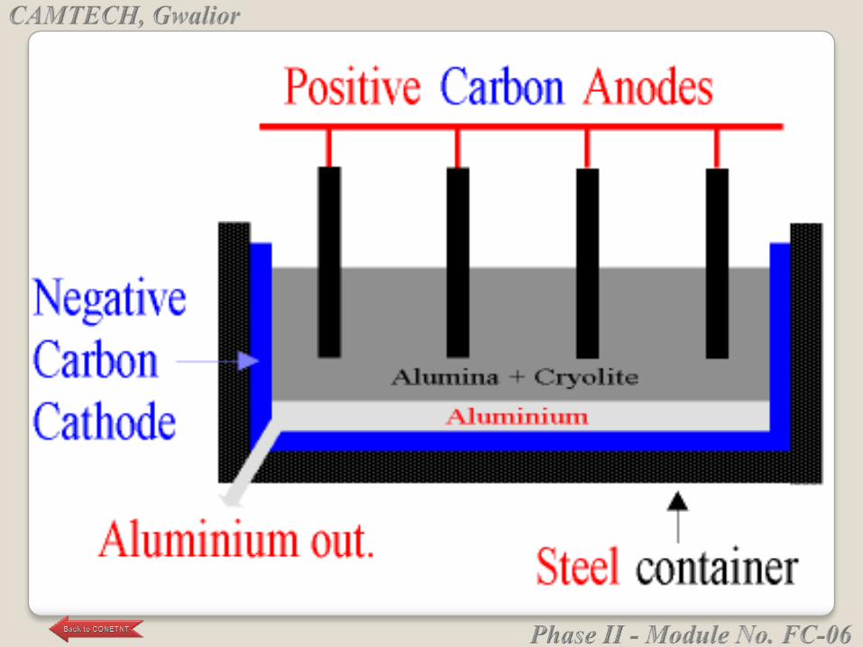
Bauxite-ore is mined and refined into alumina, one
of the feed-stocks for aluminium metal.
Then alumina and electricity are combined in a cell
with a molten electrolyte called cryolite. Direct
Current electricity is passed from a consumable
carbon anode into the cryolite, splitting the
aluminium oxide into molten aluminium metal and
carbon-dioxide.
Extraction of Aluminium
The molten aluminium collects at the bottom of the
cell and is periodically "tapped" into a crucible and
cast into ingots. While continual progress has been
made over more than 120-year history of aluminium
processing to reduce the amount of electricity used,
there are currently no viable alternatives to the
electrometallurgical process.
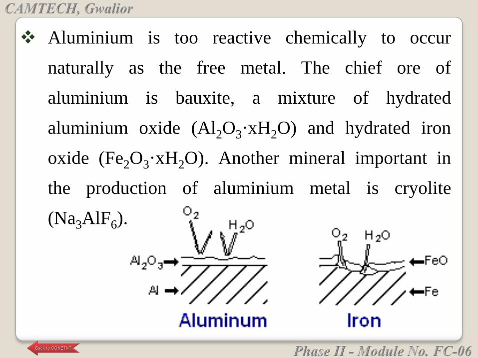
Aluminium is too reactive chemically to occur
naturally as the free metal. The chief ore of
aluminium is bauxite, a mixture of hydrated
aluminium oxide (Al2O3·xH2O) and hydrated iron
oxide (Fe2O3·xH2O). Another mineral important in
the production of aluminium metal is cryolite
(Na3AlF6).
Aluminum weathers far better than iron, however,
because the product of its corrosion, Alumina, Al2O3,
adheres strongly to the metal's surface, protecting it
from further reaction.

General Engineering:
Aircraft construction.
Electric Conductor
Building Construction
Others
Application of Al Alloys
Al is thermodynamically the least stable of main
engineering metals.... But lucky property of Al:
Formation of dense highly protective alumina film
(only 1nm in thickness)
− Can be reinforced by anodising
− Can be destroyed by salt.
Oxidation and Corrosion of Al
Cast - e.g. Al-Cu, Al-Si
Wrought - e.g. 7000 series alloys
Al Alloys
Adding Cu lowers the melting points of Al
Alloys suitable for casting
Al-Cu alloys can be age hardened
Al-Cu Alloys

Adding Si lowers the melting point of Al.
Alloys suitable for sand or die casting (high fluidity)
Al and Si have no solid solubility below the eutectic
So obtain microstructure of Si particles in an Al matrix
Good corrosion resistance and good weldability
Microstructure can be refined by rapid cooling to
increase strength and ductility.
Or microstructure by adding Sr.
Al – Si Alloys
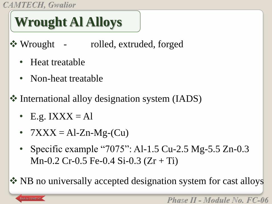
Wrought - rolled, extruded, forged
• Heat treatable
• Non-heat treatable
International alloy designation system (IADS)
• E.g. IXXX = Al
• 7XXX = Al-Zn-Mg-(Cu)
• Specific example ―7075‖: Al-1.5 Cu-2.5 Mg-5.5 Zn-0.3
Mn-0.2 Cr-0.5 Fe-0.4 Si-0.3 (Zr + Ti)
NB no universally accepted designation system for cast alloys
Wrought Al Alloys
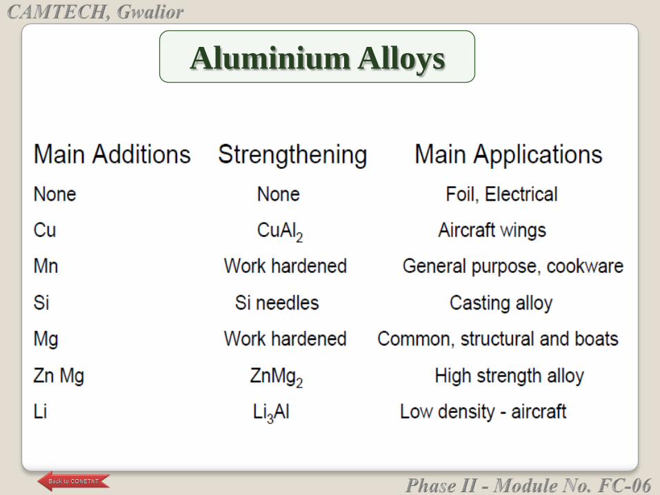
Aluminium Alloys
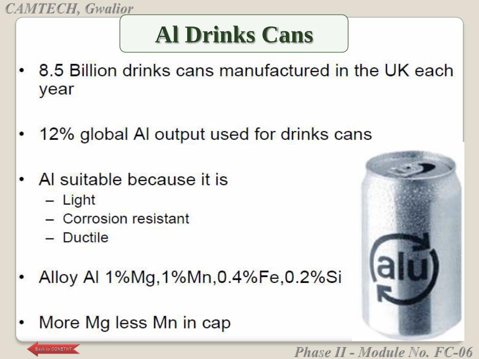
Al Drinks Cans
2. COPPER
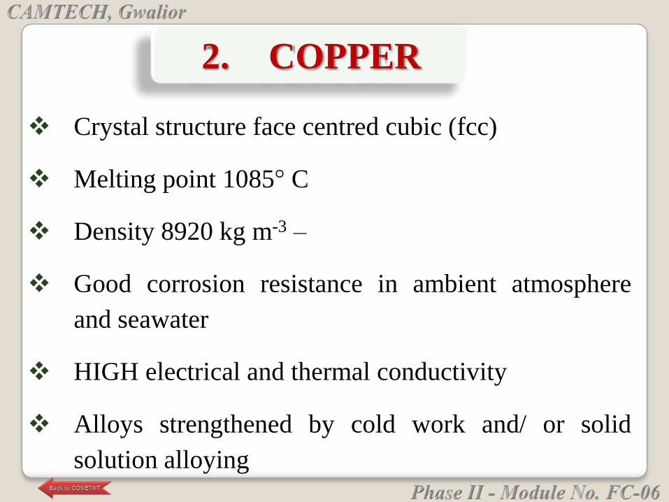
Crystal structure face centred cubic (fcc)
Melting point 1085° C
Density 8920 kg m-3 –
Good corrosion resistance in ambient atmosphere
and seawater
HIGH electrical and thermal conductivity
Alloys strengthened by cold work and/ or solid
solution alloying
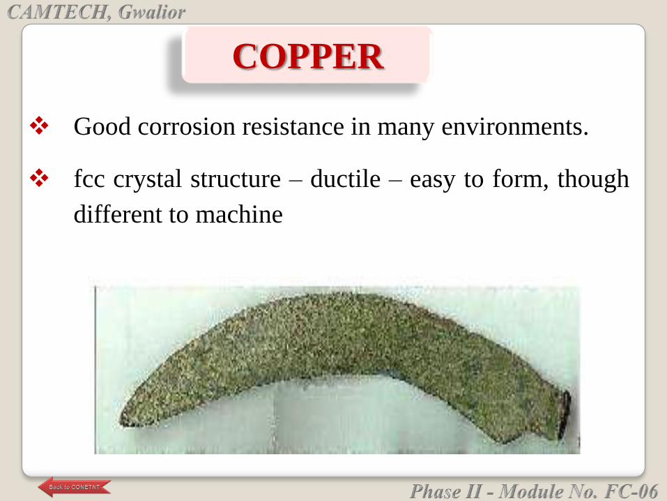
COPPER
Good corrosion resistance in many environments.
fcc crystal structure – ductile – easy to form, though
different to machine
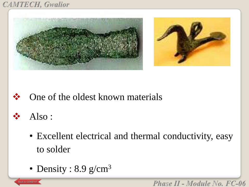
One of the oldest known materials
Also :
• Excellent electrical and thermal conductivity, easy
to solder
• Density : 8.9 g/cm3
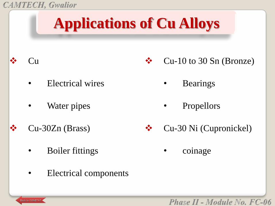
Applications of Cu Alloys
Cu
• Electrical wires
• Water pipes
Cu-30Zn (Brass)
• Boiler fittings
• Electrical components
Cu-10 to 30 Sn (Bronze)
• Bearings
• Propellors
Cu-30 Ni (Cupronickel)
• coinage
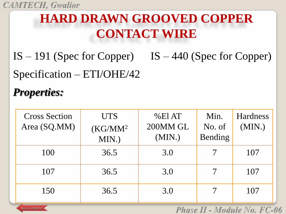
HARD DRAWN GROOVED COPPER
CONTACT WIRE
IS – 191 (Spec for Copper) IS – 440 (Spec for Copper)
Specification – ETI/OHE/42
Properties:
Cross Section
Area (SQ.MM)
UTS
(KG/MM2
MIN.)
%El AT
200MM GL
(MIN.)
Min.
No. of
Bending
Hardness
(MIN.)
100 36.5 3.0 7 107
107 36.5 3.0 7 107
150 36.5 3.0 7 107

Bending test – 90o bend & back of 200 mm straight
length by hand.
Joints to be avoided and if required by cu-ag alloy
brazing.
Microstructure – equiaxed grains with astm grain size 7
& finer for contact wire & 5 for raw material.
Hardness – bhn by 62.5 kg load and with 2.5 mm dia. As
per is:1500.
Contd…
Compression test for raw material – height to be twice of
dia. Compressed to half of height without crack.
Analysis – cu + ag more than 99.95%.
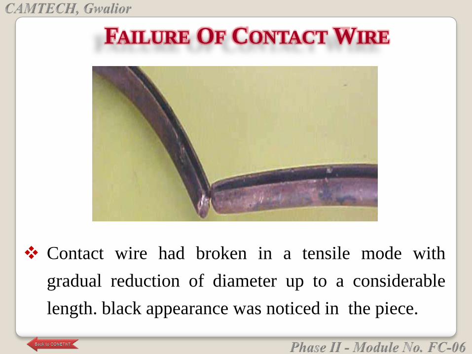
FAILURE OF CONTACT WIRE
Contact wire had broken in a tensile mode with
gradual reduction of diameter up to a considerable
length. black appearance was noticed in the piece.
Hardness; Near the fracture end 56 BHN
Away from the fracture end (unaffected area)107
BHN
Micro examination;
Near the fracture end (affected); Equi-axed grains of
copper having grain size no. 6 with twinning at
places.
For the unaffected portion; Equi-axed crystallised fine
grain structure to ASTM-7 &8
Conclusion; contact wire had failed in tensile mode.
Heating effect was revealed near the fractured end.
No sign of arcing or formation beads, crevices were
noticed in any of the pieces.
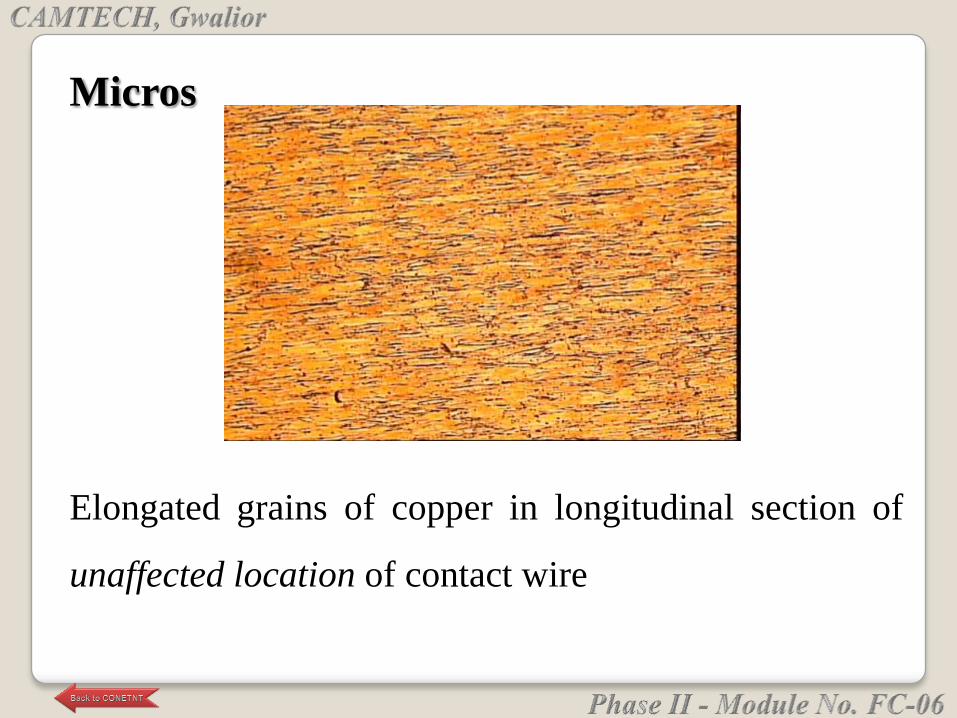
Elongated grains of copper in longitudinal section of
unaffected location of contact wire
Micros

Recrystallised grains of copper in longitudinal section
of affected location of contact wire
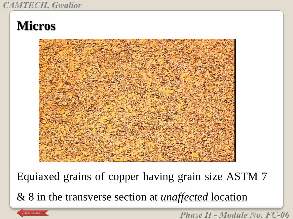
Equiaxed grains of copper having grain size ASTM 7
& 8 in the transverse section at unaffected location
Micros
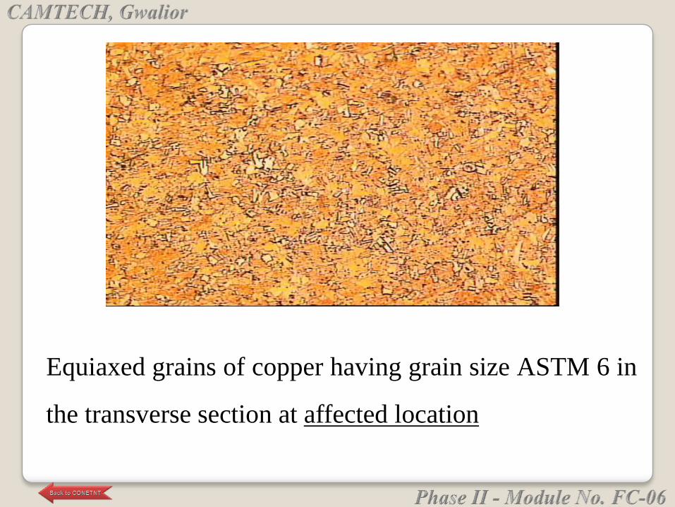
Equiaxed grains of copper having grain size ASTM 6 in
the transverse section at affected location
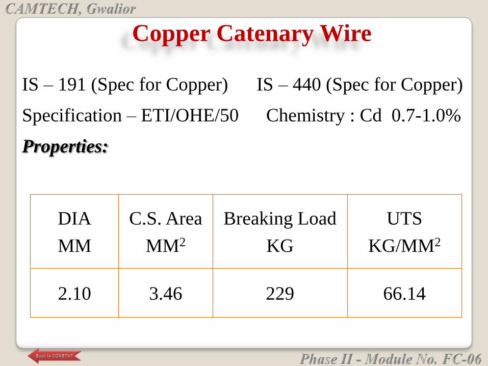
Copper Catenary Wire
IS – 191 (Spec for Copper) IS – 440 (Spec for Copper)
Specification – ETI/OHE/50 Chemistry : Cd 0.7-1.0%
Properties:
DIA
MM
C.S. Area
MM2
Breaking Load
KG
UTS
KG/MM2
2.10 3.46 229 66.14
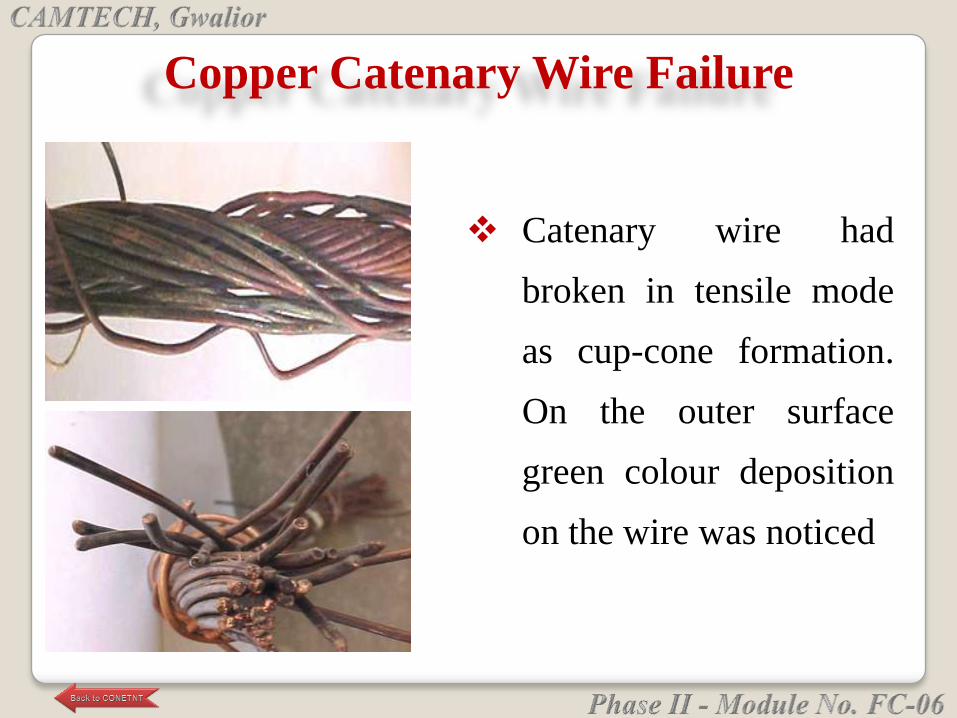
Catenary wire had
broken in tensile mode
as cup-cone formation.
On the outer surface
green colour deposition
on the wire was noticed
Copper Catenary Wire Failure
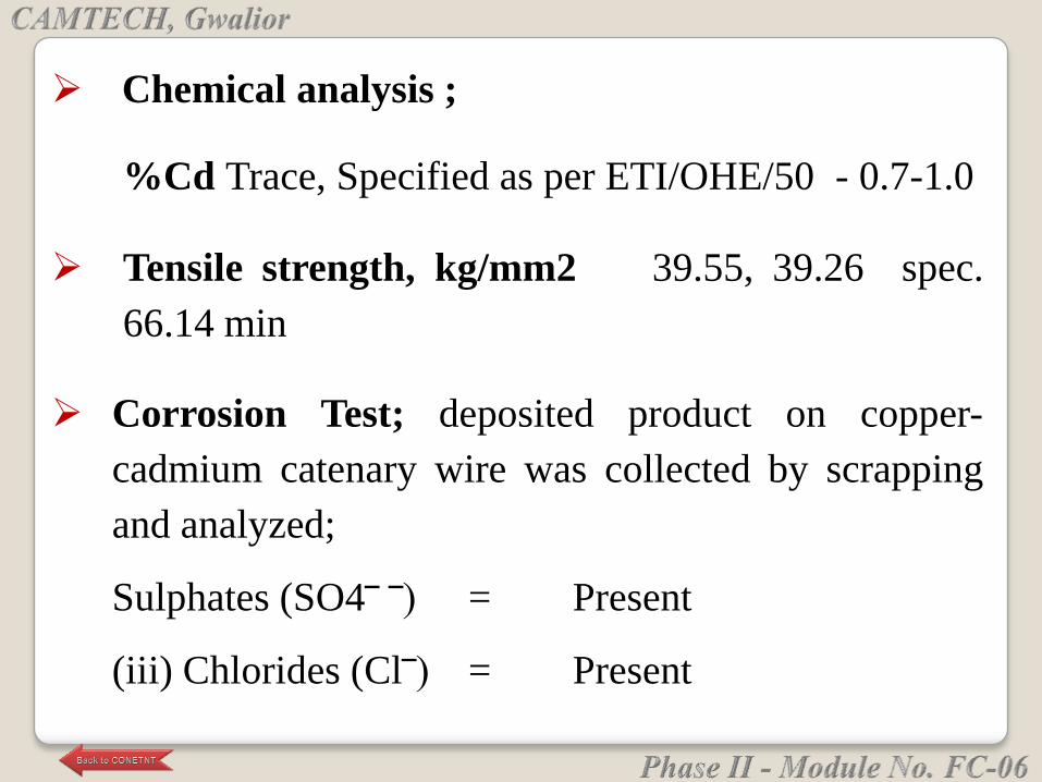
Chemical analysis ;
%Cd Trace, Specified as per ETI/OHE/50 - 0.7-1.0
Tensile strength, kg/mm2 39.55, 39.26 spec.
66.14 min
Corrosion Test; deposited product on copper-
cadmium catenary wire was collected by scrapping
and analyzed;
Sulphates (SO4‾ ‾) = Present
(iii) Chlorides (Cl‾) = Present

Conclusion; Catenary wire had broken in tensile
mode due to lower tensile strength. Absence of
cadmium has reduced the tensile strength of the
wire.
Green deposition noticed on surface is due to
presence of copper chloride and copper sulphate
and these are corrosion products.
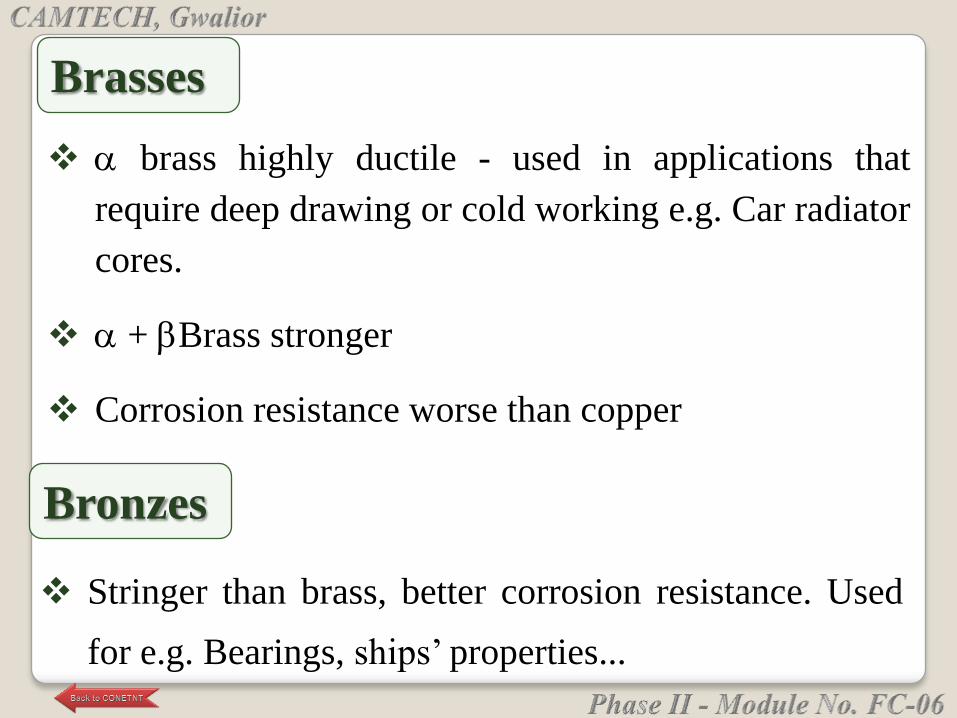
brass highly ductile - used in applications that
require deep drawing or cold working e.g. Car radiator
cores.
+ Brass stronger
Corrosion resistance worse than copper
Brasses
Stringer than brass, better corrosion resistance. Used
for e.g. Bearings, ships‘ properties...
Bronzes


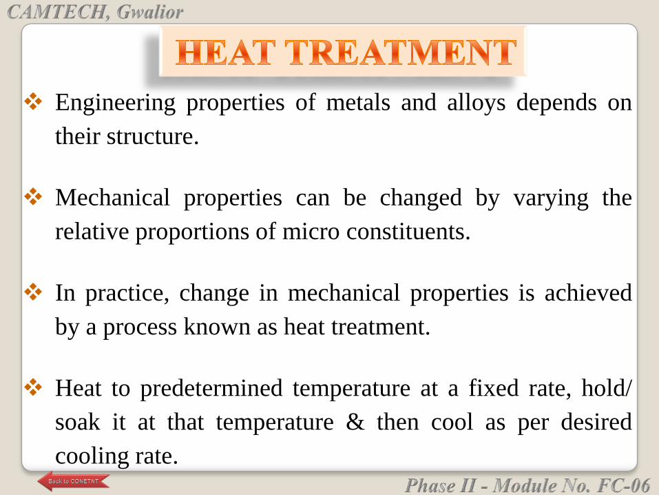
Engineering properties of metals and alloys depends on
their structure.
Mechanical properties can be changed by varying the
relative proportions of micro constituents.
In practice, change in mechanical properties is achieved
by a process known as heat treatment.
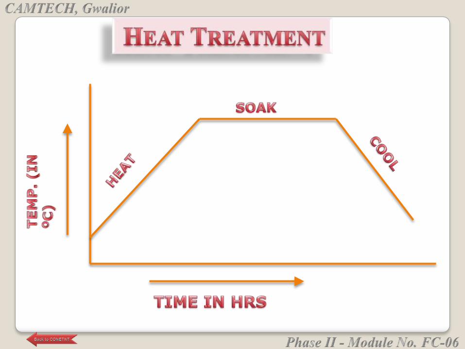
Heat to predetermined temperature at a fixed rate, hold/
soak it at that temperature & then cool as per desired
cooling rate.
Relieving internal stresses
Refinement of grain size
Improvement in ductility
Increasing hardness or tensile strength
Improvement in machinability and toughness
Achieving changes in chemical composition of metal
surface as in case of case-hardening.
Development of re-crystallized structure in cold- worked
metal.
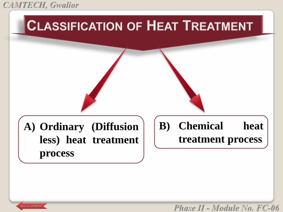
A) Ordinary (Diffusion
less) heat treatment
process
B) Chemical heat
treatment process
(A) Ordinary (Diffusion Less) Heat Treatment
Process
This kinds of heat treatment are used in practice
which affect the structure and properties to meet
the requirements made to semi fabricated
materials (castings, forgings, rolling, etc.) and
finished products.
1. Annealing
2. Normalizing
3. Hardening
4. Tempering
5. Austempering (Isothermal quenching)
6. Martempering (Stepped quenching)
7. Stress Relieving
Ordinary Heat Treatment
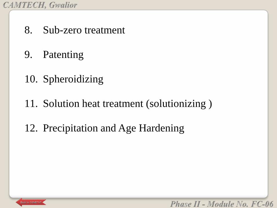
8. Sub-zero treatment
9. Patenting
10. Spheroidizing
11. Solution heat treatment (solutionizing )
12. Precipitation and Age Hardening
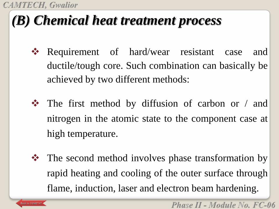
(B) Chemical heat treatment process
Requirement of hard/wear resistant case and
ductile/tough core. Such combination can basically be
achieved by two different methods:
The first method by diffusion of carbon or / and
nitrogen in the atomic state to the component case at
high temperature.
The second method involves phase transformation by
rapid heating and cooling of the outer surface through
flame, induction, laser and electron beam hardening.
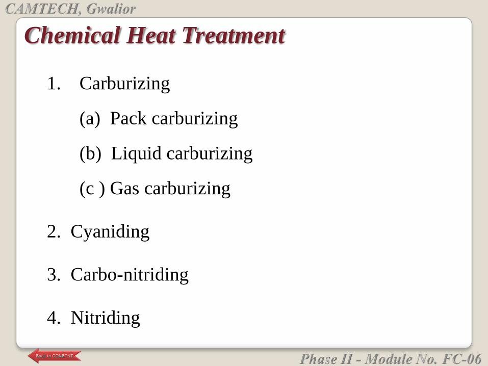
1. Carburizing
(a) Pack carburizing
(b) Liquid carburizing
(c ) Gas carburizing
2. Cyaniding
3. Carbo-nitriding
4. Nitriding
Chemical Heat Treatment
o Annealing is one of the most widely used process in
the heat treatment of iron and steel.
o It is defined as softening process consisting to heating
the steel to a temperature at or near the critical point,
holding there for a proper time and then allowing it to
cool slowly in the furnace itself.
o The temperature required for annealing varies with
different steels.
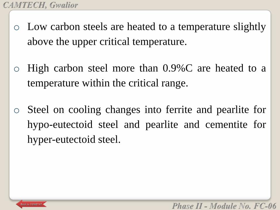
o Low carbon steels are heated to a temperature slightly
above the upper critical temperature.
o High carbon steel more than 0.9%C are heated to a
temperature within the critical range.
o Steel on cooling changes into ferrite and pearlite for
hypo-eutectoid steel and pearlite and cementite for
hyper-eutectoid steel.
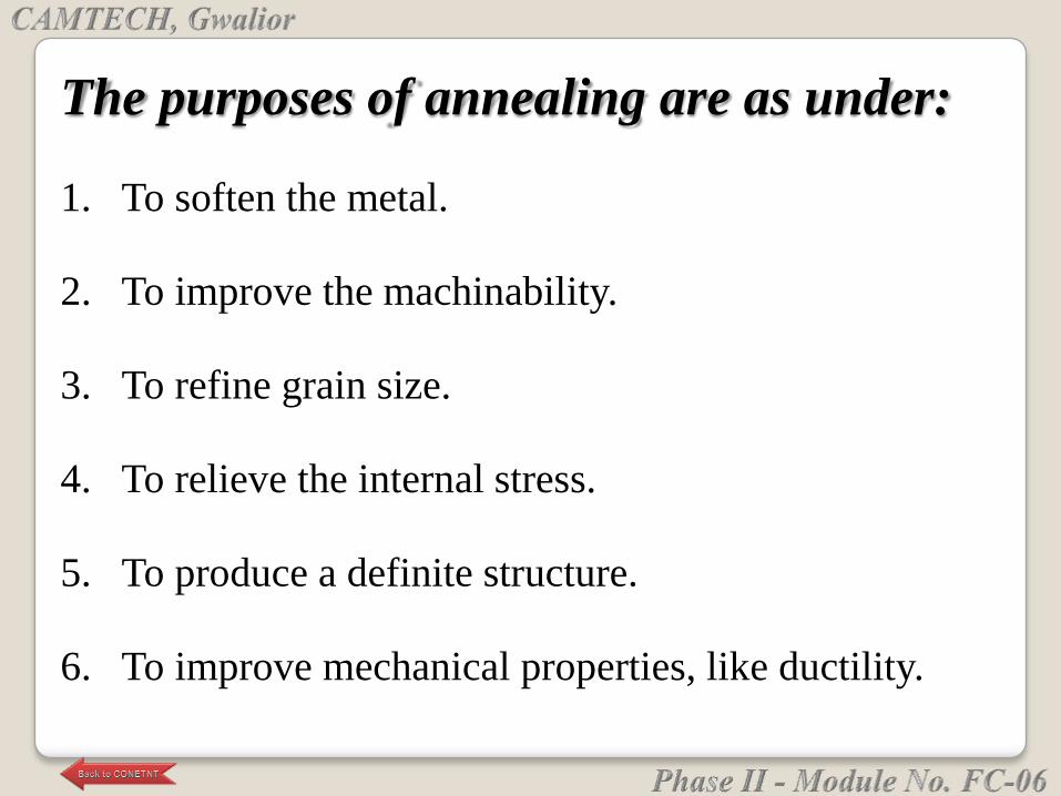
The purposes of annealing are as under:
1. To soften the metal.
2. To improve the machinability.
3. To refine grain size.
4. To relieve the internal stress.
5. To produce a definite structure.
6. To improve mechanical properties, like ductility.
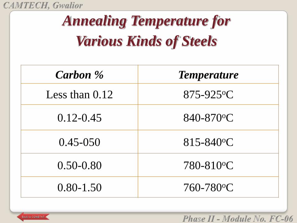
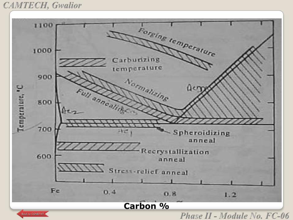
Carbon % Temperature
Less than 0.12 875-925oC
0.12-0.45 840-870oC
0.45-050 815-840oC
0.50-0.80 780-810oC
0.80-1.50 760-780oC
Annealing Temperature for
Various Kinds of Steels
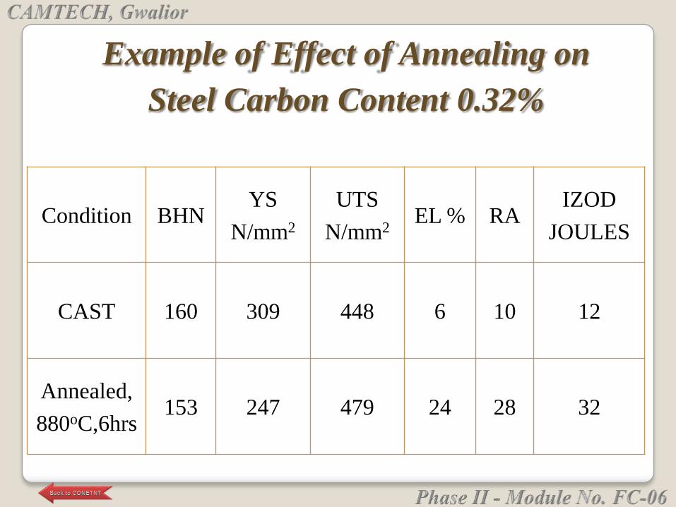
Condition BHNYS
N/mm2
UTS
N/mm2EL % RA
IZOD
JOULES
CAST 160 309 448 6 10 12
Annealed,
880oC,6hrs153 247 479 24 28 32
Example of Effect of Annealing on
Steel Carbon Content 0.32%
Carbon %
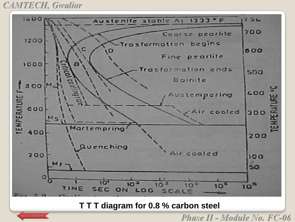
T T T diagram for 0.8 % carbon steel
Normalizing is done for refining the grain structure and
for improving the mechanical properties.
Here hypoeutectoid steel is heated above Ac3 and
hypereutectoid between Ac1 and Acm .
This is followed by cooling in dtill air. Fine pearlite and
proeutectoid ferrite results in this treatment. In
hypereutectoid steel the network of proeutectoid
cemetite is broken.
Applied to castings and forgings.
Hardness and strength is better compared to annealing.
Normalizing:-
To refine grain size
To improve machinabilty of low carbon steel
To increase strength of medium carbon steel
To reduce internal stresses.
To improve the structure of welds
To achieve certain mechanical and electrical
properties.
Objective of Normalizing
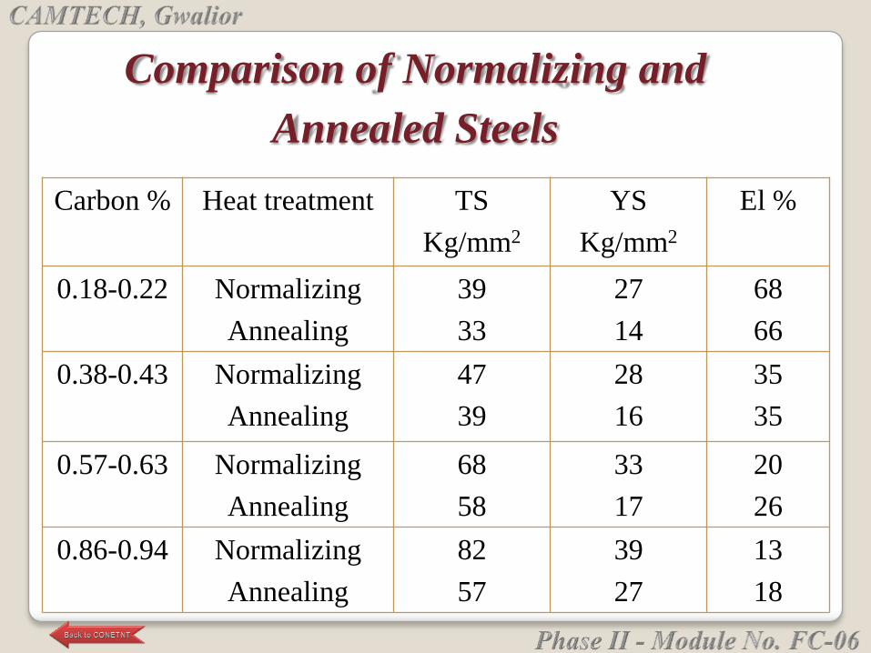
Carbon % Heat treatment TS
Kg/mm2
YS
Kg/mm2
El %
0.18-0.22 Normalizing
Annealing
39
33
27
14
68
66
0.38-0.43 Normalizing
Annealing
47
39
28
16
35
35
0.57-0.63 Normalizing
Annealing
68
58
33
17
20
26
0.86-0.94 Normalizing
Annealing
82
57
39
27
13
18
Comparison of Normalizing and
Annealed Steels
Certain applications demand high hardness values so that
the components may be successfully used for heavy duty
purposes.
High hardness values can be obtained by a process known
as hardening.
It is defined as the heat treatment process in which steel is
heated to a temperature within or above its critical
temperature, held at this temperature for a considerable
time and then allowed to cool by quenching in water, oil or
salt solution.
This high hardness developed by this process is due
to the phase transformation accompanying rapid
cooling.
Objects of hardening
● To develop high hardness in the metals for resist wear
and to enable it to cut other materials.
Factors for hardening
● The hardness obtained from hardening process
depends upon the following factors:
1. Carbon content
2. Quenching rate
3. Size and shape of steel part
Carbon content
• The hardening process is carried out on high carbon
steels because the hardness in steel is due to carbon
content only.
• It is also applied on tool and structural steel. Steel
with low carbon content will not respond appreciably
to hardening treatments.
• As carbon content in the steel increases up to 0.6% ,
the possible hardness obtainable also increases.
Above this point the hardness can be increased only
slightly, because steels above the eutectoid point are
made up of pearlite and cementite in the annealed
state.
The hardness depends essentially upon the quenching
rate. A very rapid quenching is necessary to harden low
and medium plain carbon steels.
Quenching in water bath is a method of rapid cooling and
is used for low and medium plain carbon steels.
For high carbon and alloy steels oil is used for quenching
because its action is not so sever as that of water.
It is seen that faster the cooling the greater the hardness,
slower the cooling, lower the hardness.
Size and shape
Material size also affects the hardness obtained from
hardening process.
After the hardening, tempering is carried out because
the hardened steel is brittle and unsuitable for most
uses due to poor ductility, toughness and impact
strength.
The tempering is defined as the process of reheating
the hardened steel to some temperature below the
critical range followed by cooling in air or any other
desired rate.
Objective of tempering
To reduce hardness, brittleness and tensile strength.
To increase ductility and toughness.
To relieve quenching stress.
It is one of the process of heat treatment of metals
and its alloys by which the surface of the metals is
made hard and wear resistant which is called ‗case‘
and at the same time the inside of the metals
remains soft and tough which is called ‗core‘ of the
metals and so case hardening is also called
sometimes surface hardening.
Case-Hardening (Surface hardening)
It is generally used for the heat treatment of crankshaft,
camshaft, gears, crank pins, axles and wide range of
automobiles.
In this process, heating of the component is achieved
by electromagnetic induction.
An induction coil carries an alternating current of high
frequency which is then induced in the enclosed steel
part placed within the magnetic field of coil. As a
result, induction heating takes place. Immediately after
heating water jet is sprayed on the surface.
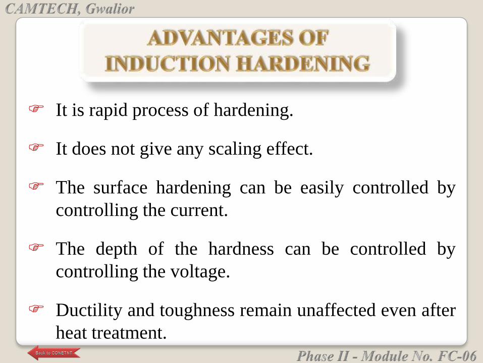
It is rapid process of hardening.
It does not give any scaling effect.
The surface hardening can be easily controlled by
controlling the current.
The depth of the hardness can be controlled by
controlling the voltage.
Ductility and toughness remain unaffected even after
heat treatment.
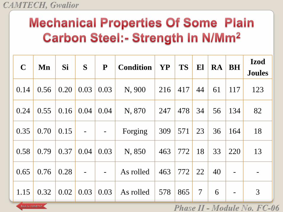
C Mn Si S P Condition YP TS El RA BHIzod
Joules
0.14 0.56 0.20 0.03 0.03 N, 900 216 417 44 61 117 123
0.24 0.55 0.16 0.04 0.04 N, 870 247 478 34 56 134 82
0.35 0.70 0.15 - - Forging 309 571 23 36 164 18
0.58 0.79 0.37 0.04 0.03 N, 850 463 772 18 33 220 13
0.65 0.76 0.28 - - As rolled 463 772 22 40 - -
1.15 0.32 0.02 0.03 0.03 As rolled 578 865 7 6 - 3
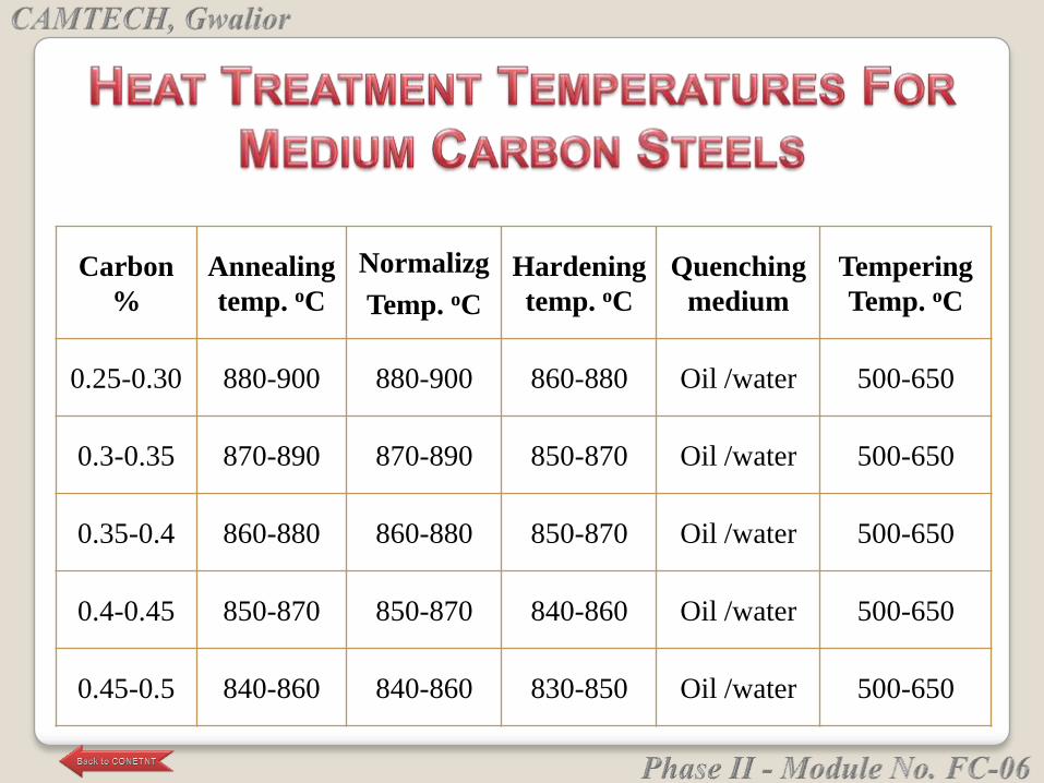
Carbon
%
Annealing
temp. oC
Normalizg
Temp. oC
Hardening
temp. oC
Quenching
medium
Tempering
Temp. oC
0.25-0.30 880-900 880-900 860-880 Oil /water 500-650
0.3-0.35 870-890 870-890 850-870 Oil /water 500-650
0.35-0.4 860-880 860-880 850-870 Oil /water 500-650
0.4-0.45 850-870 850-870 840-860 Oil /water 500-650
0.45-0.5 840-860 840-860 830-850 Oil /water 500-650
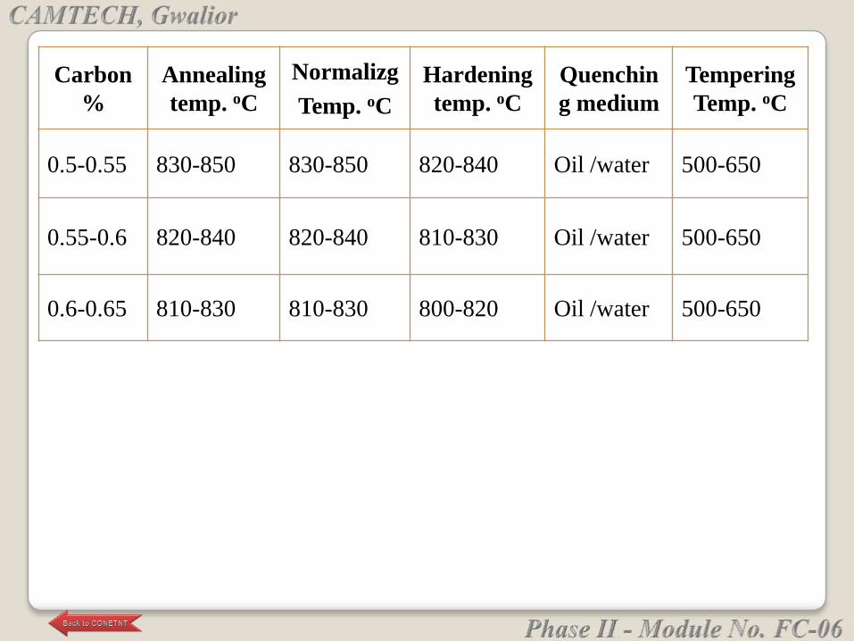
Carbon
%
Annealing
temp. oC
Normalizg
Temp. oC
Hardening
temp. oC
Quenchin
g medium
Tempering
Temp. oC
0.5-0.55 830-850 830-850 820-840 Oil /water 500-650
0.55-0.6 820-840 820-840 810-830 Oil /water 500-650
0.6-0.65 810-830 810-830 800-820 Oil /water 500-650
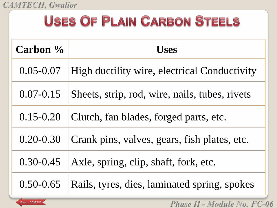
Carbon % Uses
0.05-0.07 High ductility wire, electrical Conductivity
0.07-0.15 Sheets, strip, rod, wire, nails, tubes, rivets
0.15-0.20 Clutch, fan blades, forged parts, etc.
0.20-0.30 Crank pins, valves, gears, fish plates, etc.
0.30-0.45 Axle, spring, clip, shaft, fork, etc.
0.50-0.65 Rails, tyres, dies, laminated spring, spokes
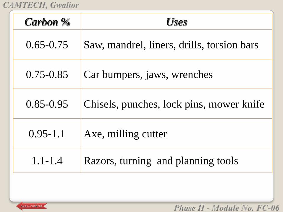
Carbon % Uses
0.65-0.75 Saw, mandrel, liners, drills, torsion bars
0.75-0.85 Car bumpers, jaws, wrenches
0.85-0.95 Chisels, punches, lock pins, mower knife
0.95-1.1 Axe, milling cutter
1.1-1.4 Razors, turning and planning tools

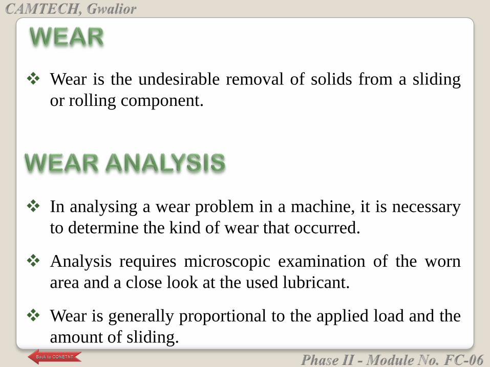
Wear is the undesirable removal of solids from a sliding
or rolling component.
In analysing a wear problem in a machine, it is necessary
to determine the kind of wear that occurred.
Analysis requires microscopic examination of the worn
area and a close look at the used lubricant.
Wear is generally proportional to the applied load and the
amount of sliding.
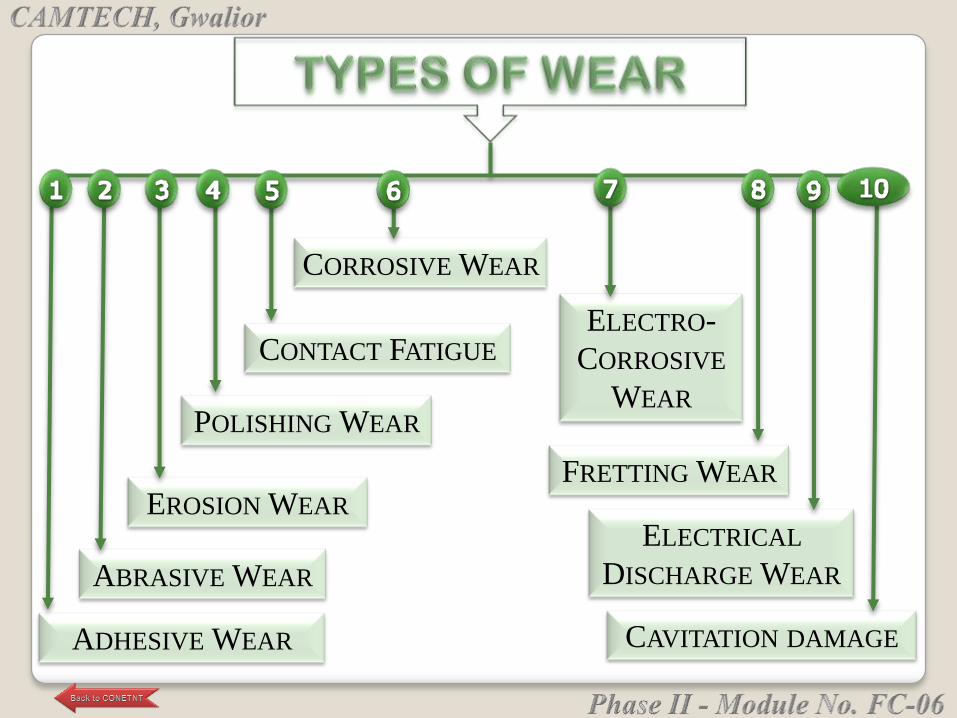
ADHESIVE WEAR
ELECTRO-
CORROSIVE
WEAR
ABRASIVE WEAR
EROSION WEAR
POLISHING WEAR
CONTACT FATIGUE
CORROSIVE WEAR
FRETTING WEAR
ELECTRICAL
DISCHARGE WEAR
CAVITATION DAMAGE
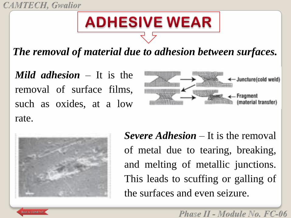
The removal of material due to adhesion between surfaces.
Severe Adhesion – It is the removal
of metal due to tearing, breaking,
and melting of metallic junctions.
This leads to scuffing or galling of
the surfaces and even seizure.
Mild adhesion – It is the
removal of surface films,
such as oxides, at a low
rate.
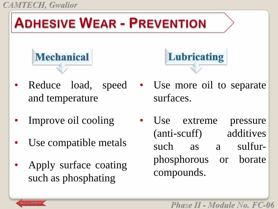
• Reduce load, speed
and temperature
• Improve oil cooling
• Use compatible metals
• Apply surface coating
such as phosphating
• Use more oil to separate
surfaces.
• Use extreme pressure
(anti-scuff) additives
such as a sulfur-
phosphorous or borate
compounds.
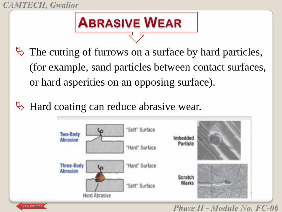
The cutting of furrows on a surface by hard particles,
(for example, sand particles between contact surfaces,
or hard asperities on an opposing surface).
Hard coating can reduce abrasive wear.
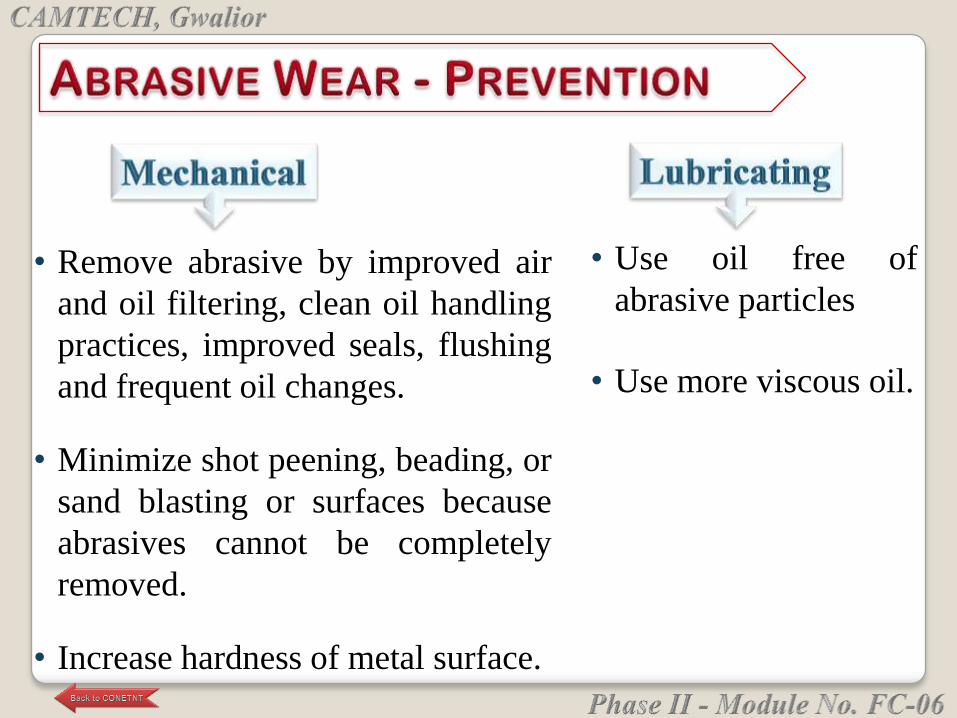
• Remove abrasive by improved air
and oil filtering, clean oil handling
practices, improved seals, flushing
and frequent oil changes.
• Minimize shot peening, beading, or
sand blasting or surfaces because
abrasives cannot be completely
removed.
• Increase hardness of metal surface.
• Use oil free of
abrasive particles
• Use more viscous oil.

The cutting of furrows on a surface by hard particles
contained in a fluid travelling at high velocity.

• Use oil free of
abrasive particles.
• Use more viscous oil.
• Remove abrasive by improved
air and oil filtering, clean oil
handling practices, improved
seals, flushing and frequent oil
changes.
• Reduce impact angle to less
than 15 degree.
• Increase hardness of metal
surface.
The continuous removal of surface films, laid down
via a chemical reaction from an additive in oil or by
very fine hard particles in the lubricant, and so on.
Polishing wear is characterized by very shiny, very
smooth, mirror like metal surfaces. Fine abrasives
wear away the surface films as they form and reform.
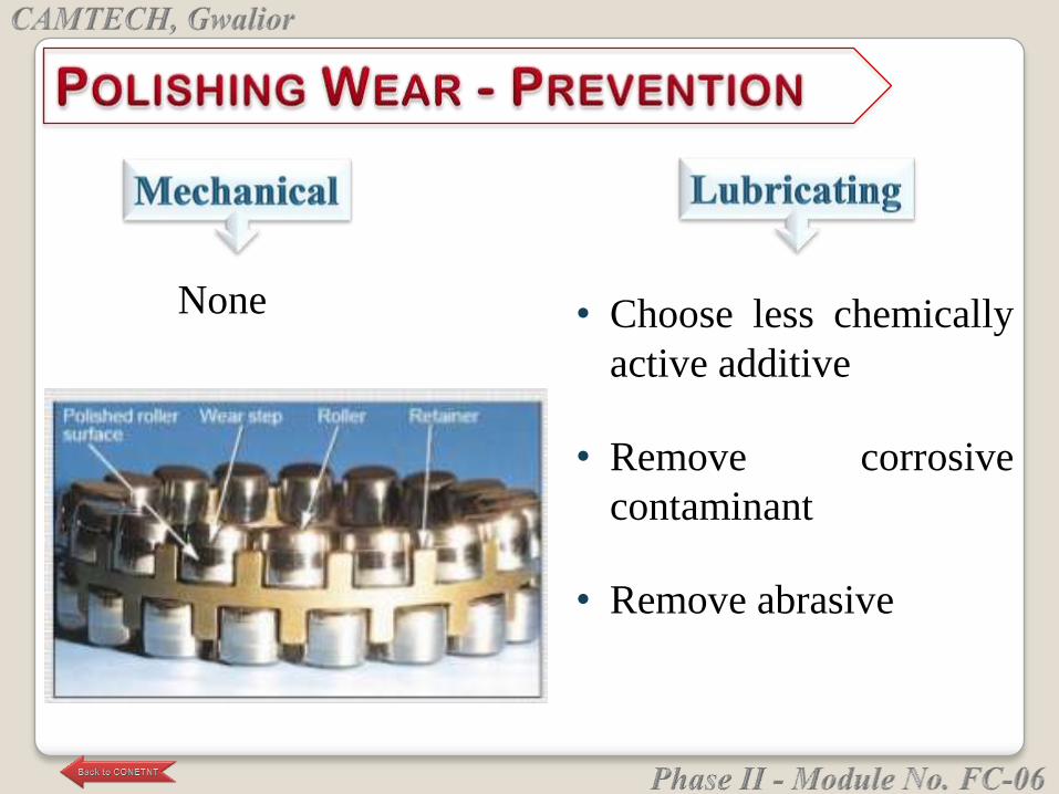
• Choose less chemically
active additive
• Remove corrosive
contaminant
• Remove abrasive
None
The cracking, pitting and spalling of a surface in
sequence due to cyclic stresses in a contact.
Contact fatigue is most common in rolling element
bearings, gear teeth and cams.
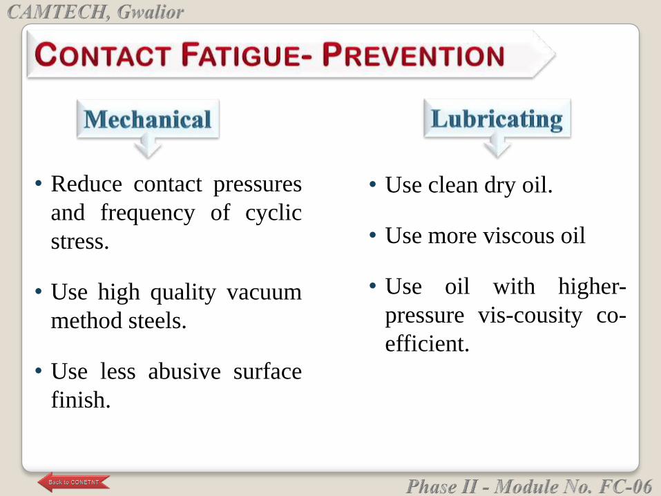
• Use clean dry oil.
• Use more viscous oil
• Use oil with higher-
pressure vis-cousity co-
efficient.
• Reduce contact pressures
and frequency of cyclic
stress.
• Use high quality vacuum
method steels.
• Use less abusive surface
finish.
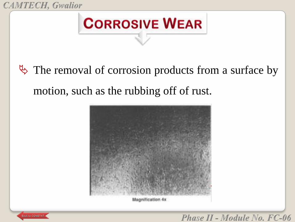
The removal of corrosion products from a surface by
motion, such as the rubbing off of rust.
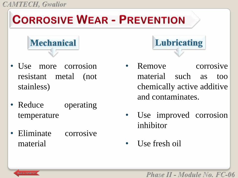
• Remove corrosive
material such as too
chemically active additive
and contaminates.
• Use improved corrosion
inhibitor
• Use fresh oil
• Use more corrosion
resistant metal (not
stainless)
• Reduce operating
temperature
• Eliminate corrosive
material
The removal of metal by dissolution in a corrosive
liquid with the aid of electric currents
One source of currents is streaming potential from
high velocity fluids.
The oil serves as the electrolyte.
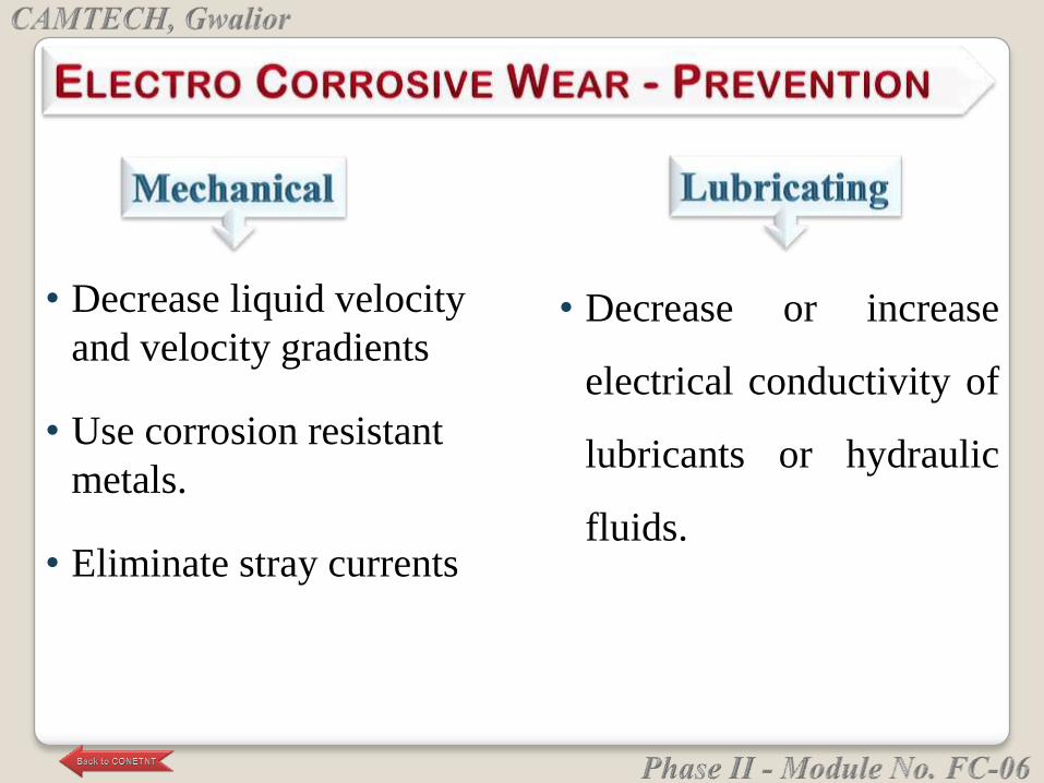
• Decrease or increase
electrical conductivity of
lubricants or hydraulic
fluids.
• Decrease liquid velocity
and velocity gradients
• Use corrosion resistant
metals.
• Eliminate stray currents
Localized wear of lubricating surfaces due to
reciprocating sliding of extremely low amplitude
because of vibration.
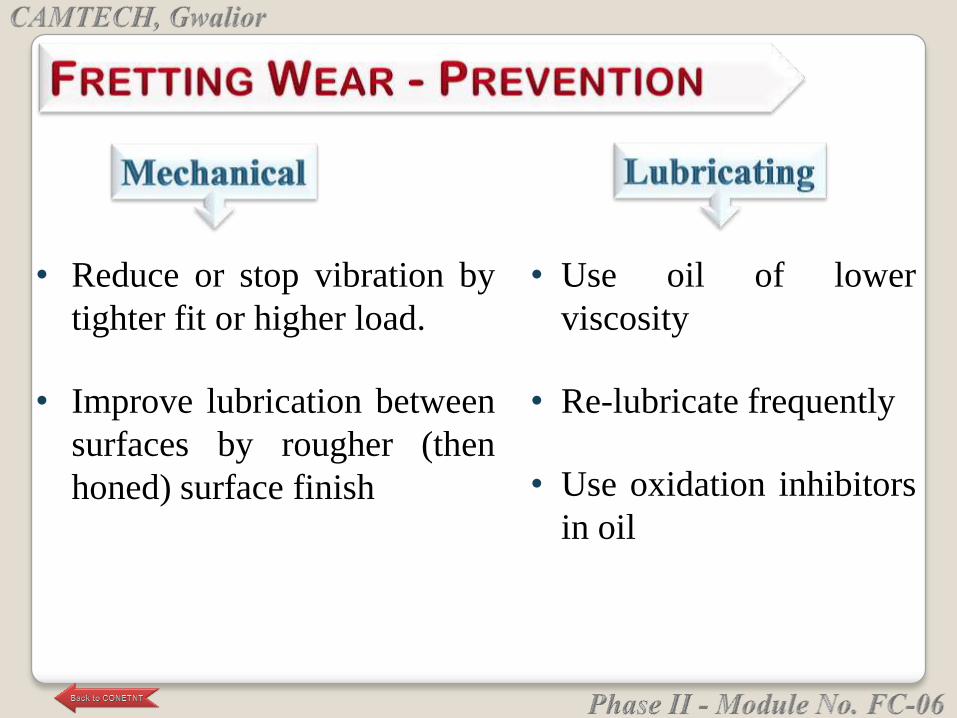
• Use oil of lower
viscosity
• Re-lubricate frequently
• Use oxidation inhibitors
in oil
• Reduce or stop vibration by
tighter fit or higher load.
• Improve lubrication between
surfaces by rougher (then
honed) surface finish
The removal of molten metal from surfaces due
to electrical sparks between them.
High static voltages are sometimes generated by
large rotating machinery and these are relieved
by sparking to regions of lower potential.
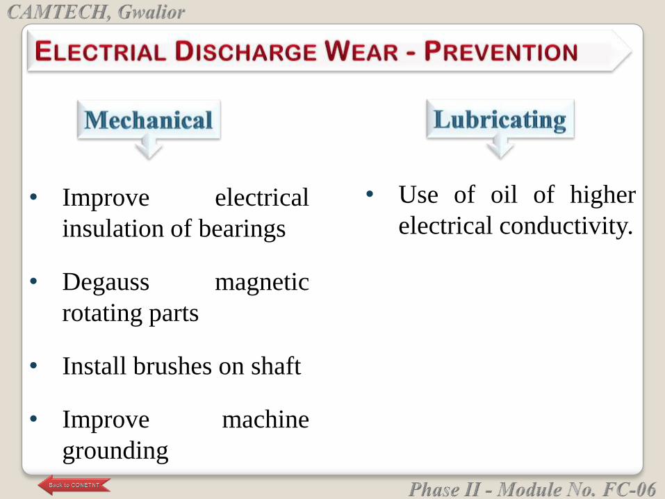
• Use of oil of higher
electrical conductivity.• Improve electrical
insulation of bearings
• Degauss magnetic
rotating parts
• Install brushes on shaft
• Improve machine
grounding
The removal of material due to cracking and pitting
caused by high energy implosions of vacuous
cavities in a cavitating liquid.
Liquids cavitate when suddenly subjected to low
pressures.
Removal of metal by vapor cavity implosion in a
cavitating liquid.
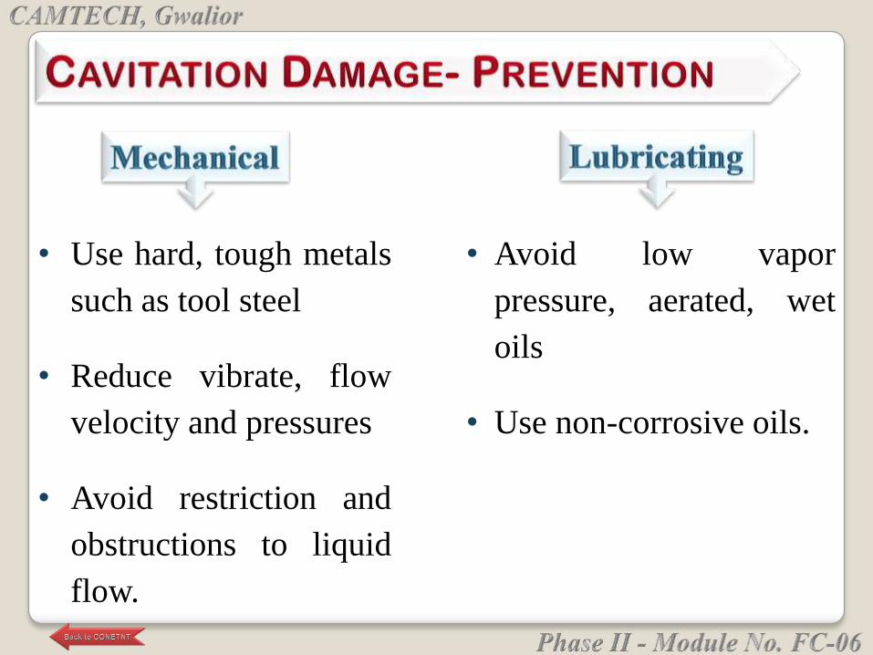
• Avoid low vapor
pressure, aerated, wet
oils
• Use non-corrosive oils.
• Use hard, tough metals
such as tool steel
• Reduce vibrate, flow
velocity and pressures
• Avoid restriction and
obstructions to liquid
flow.
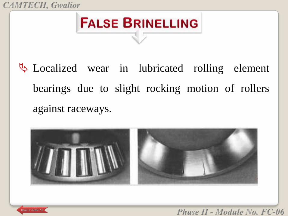
Localized wear in lubricated rolling element
bearings due to slight rocking motion of rollers
against raceways.
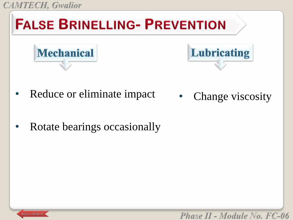
• Change viscosity• Reduce or eliminate impact
• Rotate bearings occasionally
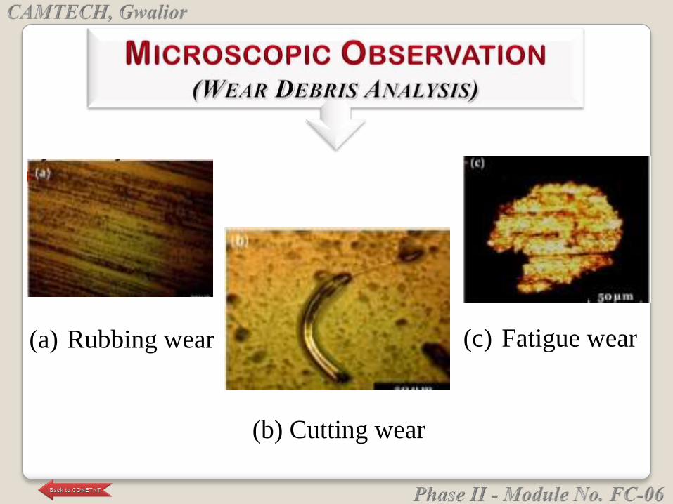
(a) Rubbing wear
(b) Cutting wear
(c) Fatigue wear
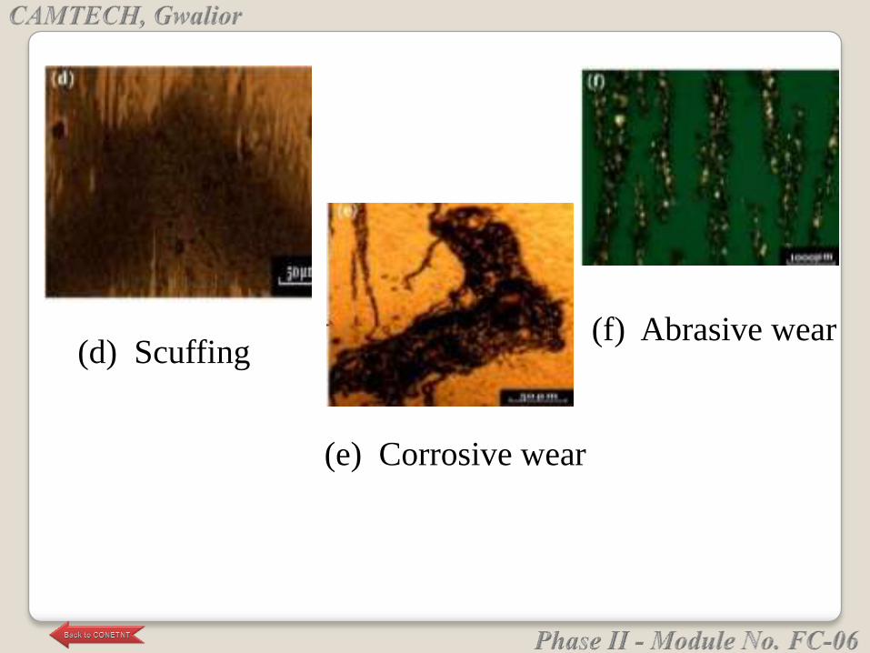
(d) Scuffing
(e) Corrosive wear
(f) Abrasive wear


Bearings are machine elements which are used to
support a rotating member called as shaft.
They transmit the load from a rotating member to a
stationary member known as frame or housing.
INTRODUCTION
Common motions permitted by bearings are:
Axial rotation e.g. shaft rotation
Linear motion e.g. Carriage over the bed, drawer in
the table
Spherical rotation e.g. ball and socket joint
Hinge motion e.g. door
BEARING MOTIONS
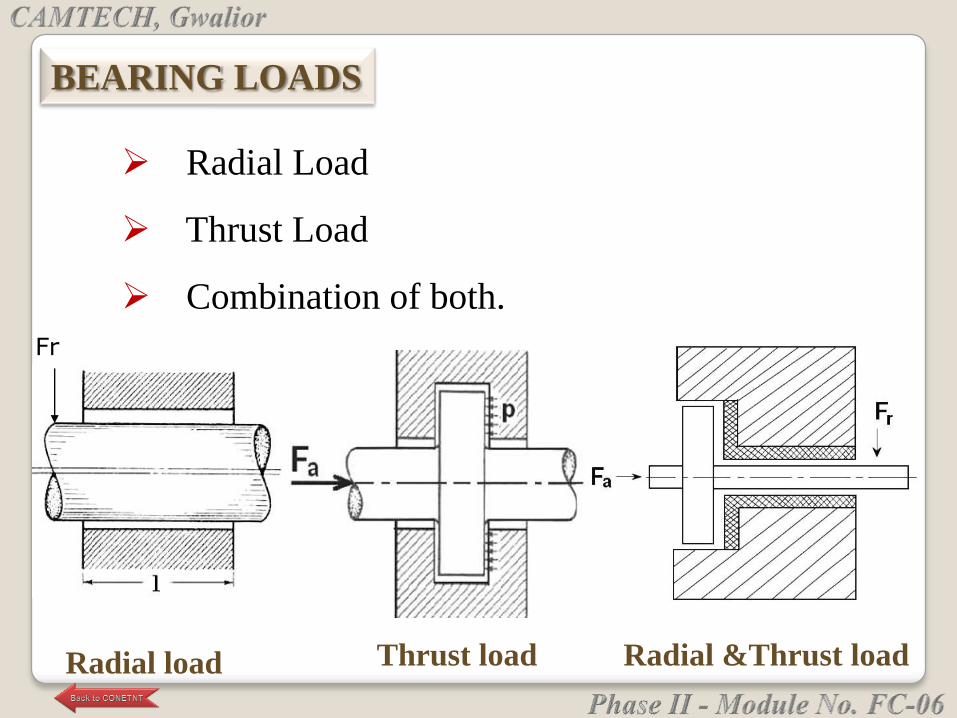
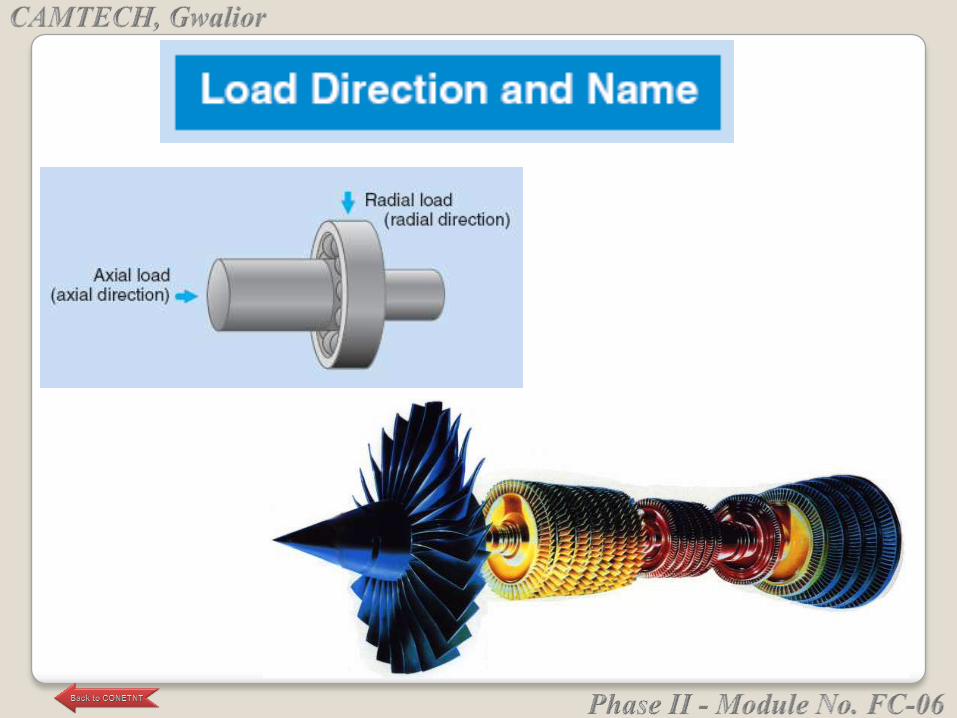
Radial Load
Thrust Load
Combination of both.
Fr
Radial load Thrust load Radial &Thrust load
BEARING LOADS
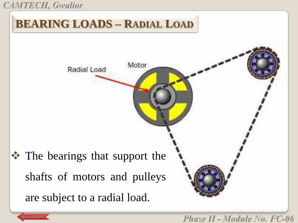
The bearings that support the
shafts of motors and pulleys
are subject to a radial load.
BEARING LOADS – RADIAL LOAD
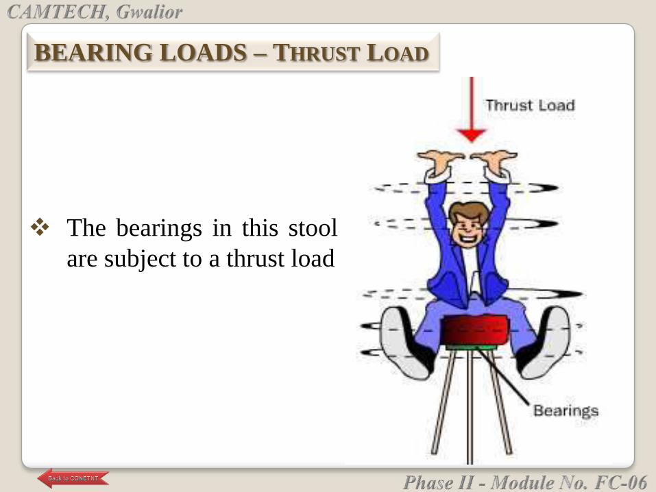
The bearings in this stool
are subject to a thrust load
BEARING LOADS – THRUST LOAD

The bearings in a car
wheel are subject to
both thrust and radial
loads.
BEARING LOADS –
COMBINATION OF RADIAL & THRUST LOAD
The main function of a rotating shaft is to transmit
power from one end of the line to the other.
It needs a good support to ensure stability and
frictionless rotation. The support for the shaft is
known as “bearing”.
The shaft has a ―running fit‖ in a bearing. All
bearing are provided some lubrication arrangement
to reduced friction between shaft and bearing.
FUNCTION OF A BEARING
Each bearing type displays characteristic properties,
based on its design which makes it more, or less
appropriate for a given application.
The most important factors to be considered when
selecting a standard bearing type and thus a facilitate
an appropriate choice :
● Available space
● Loads
● Misalignment
SELECTION OF BEARING TYPE
● Precision
● Speed
● Quiet running
● Stiffness
● Axial displacement
● Mounting and dismounting
● Integral seals

Plain or
slider bearing
Rolling or anti-
friction bearing

In which the rotating shaft has a sliding contact with the
bearing which is held stationary . Due to large contact area
friction between mating parts is high requiring greater
lubrication.
Plain or slider bearing
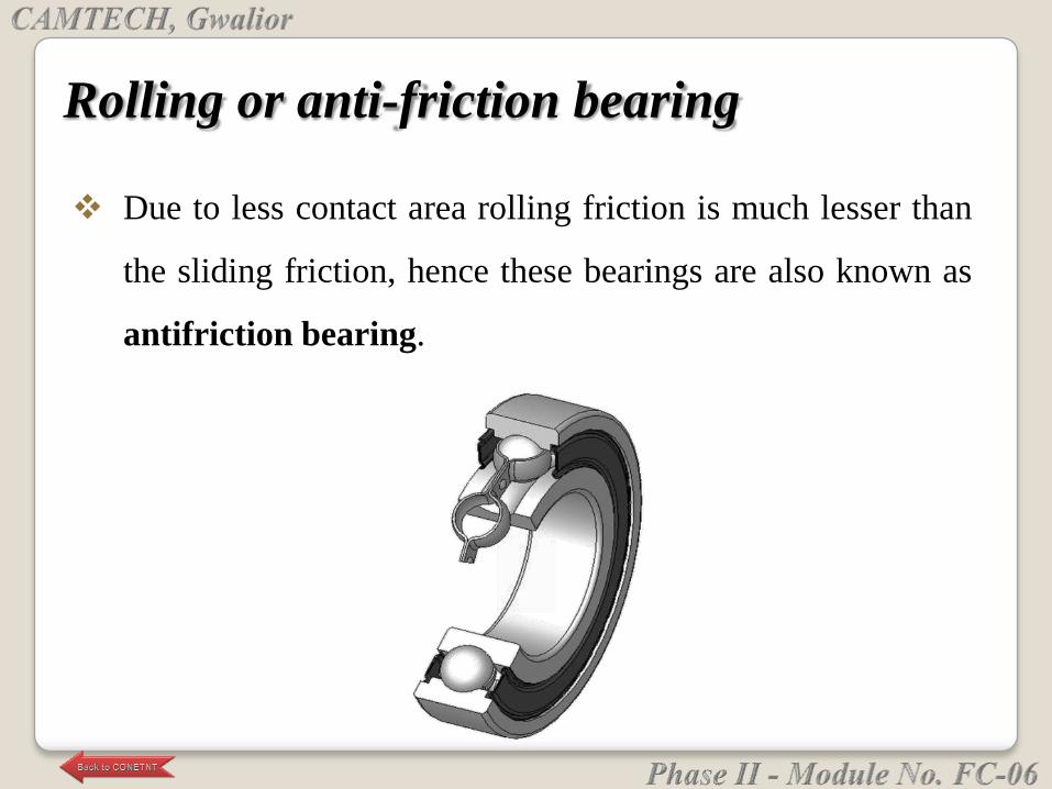
Due to less contact area rolling friction is much lesser than
the sliding friction, hence these bearings are also known as
antifriction bearing.
Rolling or anti-friction bearing
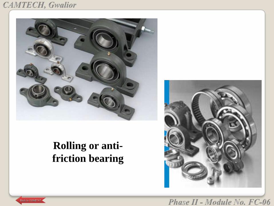
Rolling or anti-
friction bearing
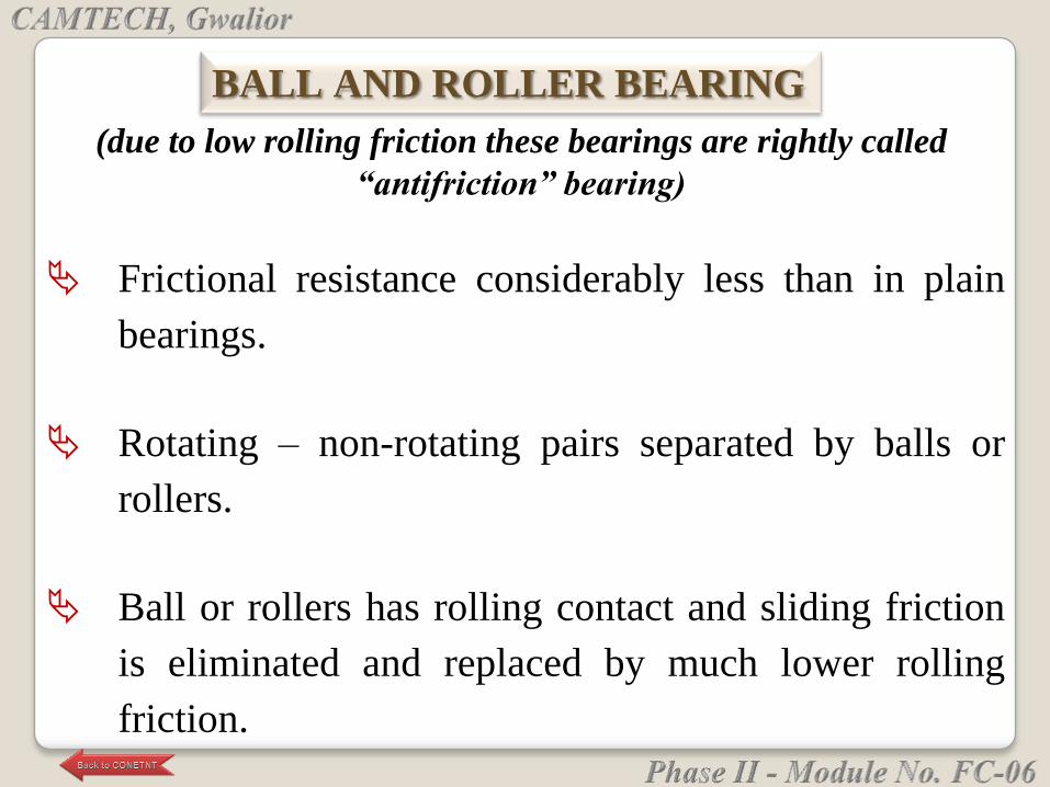
(due to low rolling friction these bearings are rightly called
“antifriction” bearing)
Frictional resistance considerably less than in plain
bearings.
Rotating – non-rotating pairs separated by balls or
rollers.
Ball or rollers has rolling contact and sliding friction
is eliminated and replaced by much lower rolling
friction.
BALL AND ROLLER BEARING
In plain bearing the starting resistance is much larger
than the running resistance due to absence of oil film.
In ball and rolling bearings the initial resistance to
motion is only slightly more than their resistance to
continuous running.
Hence ball and rolling bearing are more suitable to
drives subject to frequent starting and stopping as they
save power.
Owing to the low starting torque, a low power motor
can be used for a line shaft running in ball bearing.
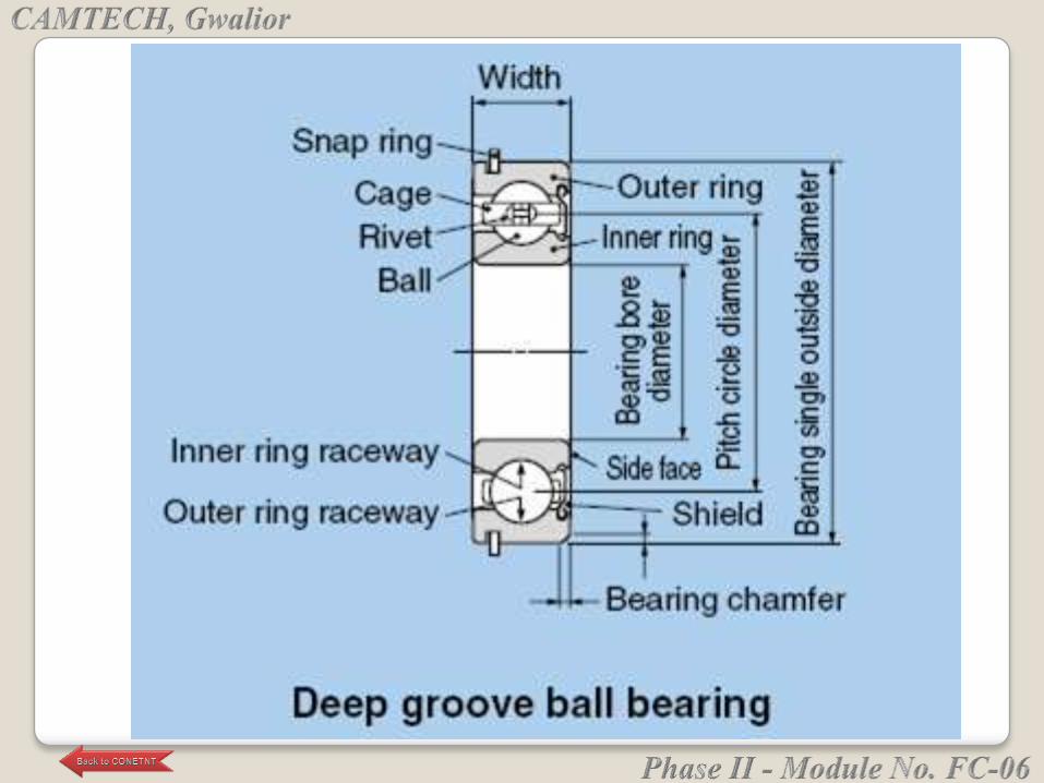
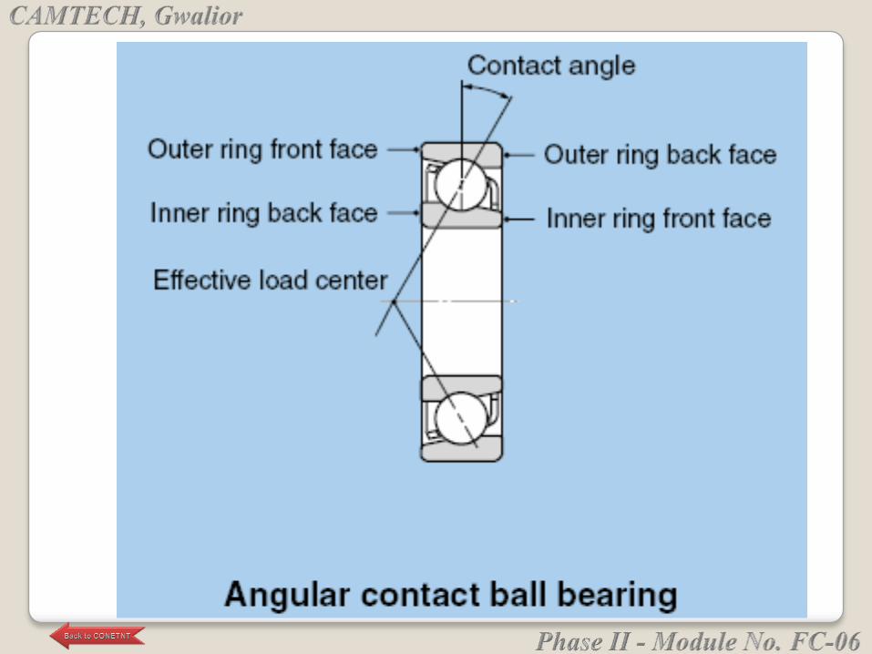
Single row deep-groove ball bearing:
• Incorporating a deep hardened raceway which
makes them suitable for radial and axial loads in
either direction, provided the radial loads are
greater than the axial loads.
TYPES OF ROLLER BEARING
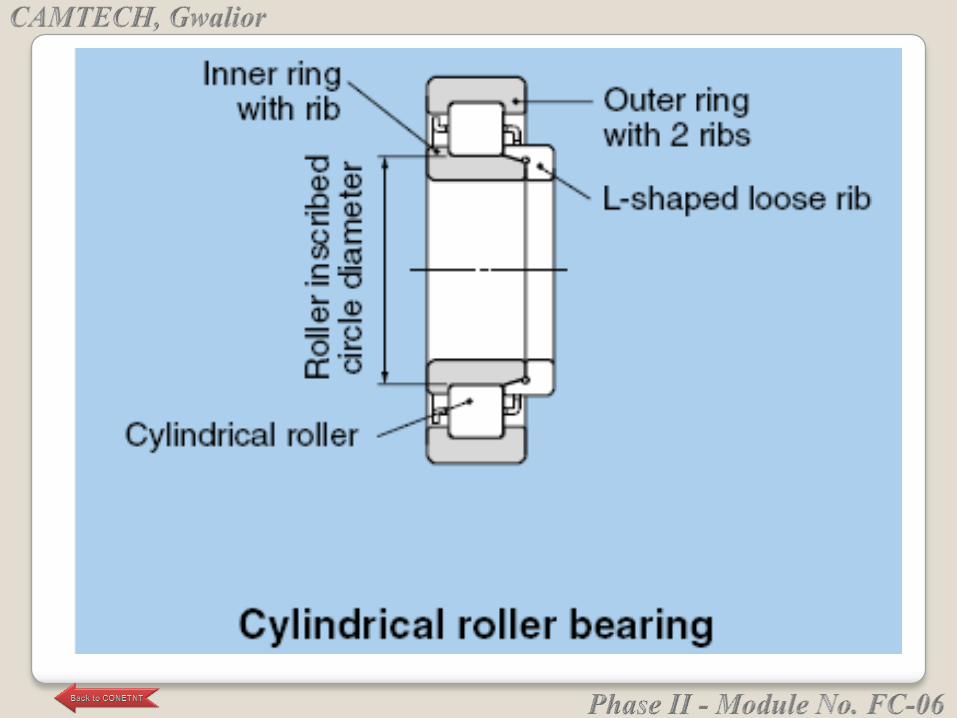
Single row roller bearing:
• Roller bearing have a greater load-carrying
capacity than ball bearing of equivalent size as
they make line contact rather than point contact
with their rings.
• Not suitable for axial loading, cheaper to
manufacture, used for heavy and sudden
loading, high speed and continuous service.
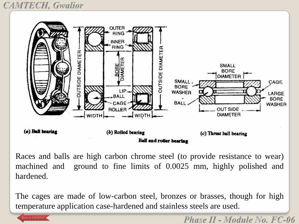
Races and balls are high carbon chrome steel (to provide resistance to wear)
machined and ground to fine limits of 0.0025 mm, highly polished and
hardened.
The cages are made of low-carbon steel, bronzes or brasses, though for high
temperature application case-hardened and stainless steels are used.
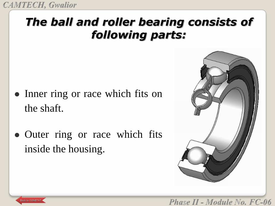
The ball and roller bearing consists of following parts:
Inner ring or race which fits on
the shaft.
Outer ring or race which fits
inside the housing.
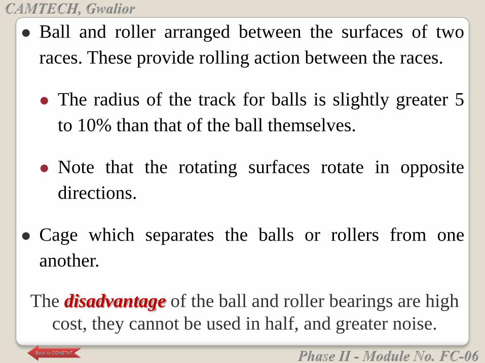
Ball and roller arranged between the surfaces of two
races. These provide rolling action between the races.
The radius of the track for balls is slightly greater 5
to 10% than that of the ball themselves.
Note that the rotating surfaces rotate in opposite
directions.
Cage which separates the balls or rollers from one
another.
The disadvantage of the ball and roller bearings are high
cost, they cannot be used in half, and greater noise.
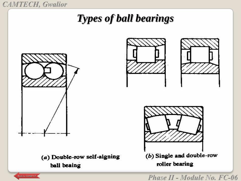
Types of ball bearings
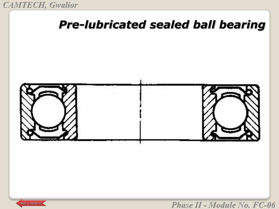
Pre-lubricated sealed ball bearing
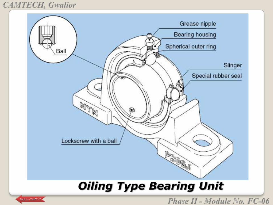
Oiling Type Bearing Unit
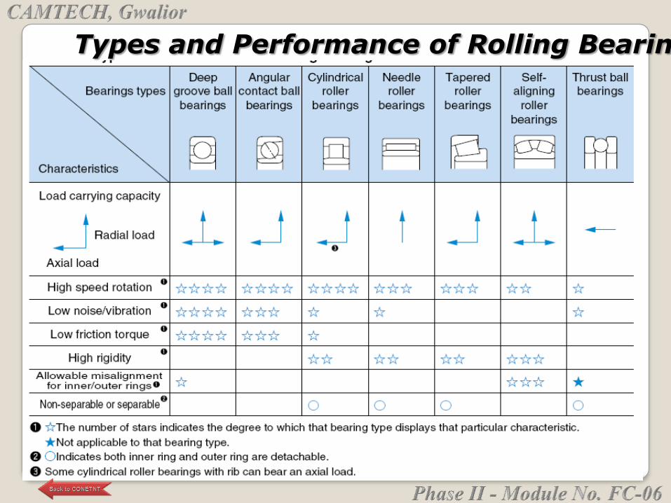
Types and Performance of Rolling Bearing
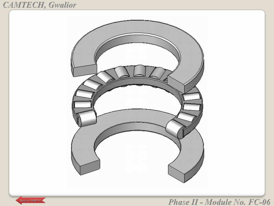
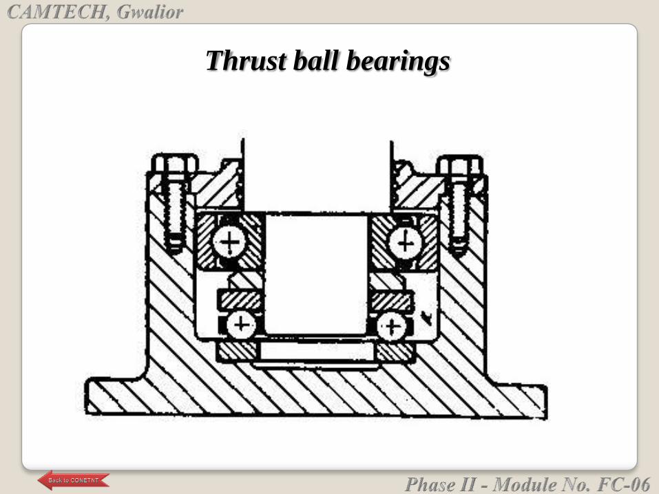
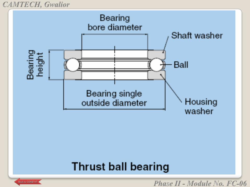
Thrust ball bearings
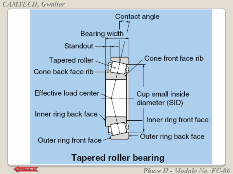
Tapered roller bearing (TRB):
• TRB can take both radial and axial loads and used
for gear boxes for heavy trucks, bevel-gear
transmission, lathe spindles, etc.
Thrust ball bearing:
• It can take only thrust loads.
• Thrust ball bearing are used for heavy axial loads
and low speeds.
APPLICATIONS OF ROLLER BEARINGS
Needle roller bearing:
• It use small diameter of rollers. They are used for
radial load at slow speed and oscillating motion.
• They have the advantage of light weight and
occupy small space.
• They are used in aircraft industry, live tail stock
centers, bench-drill spindles, etc.
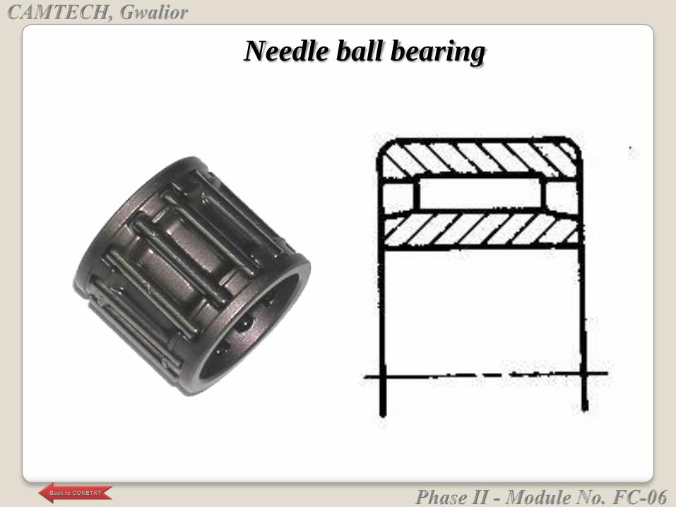
Needle ball bearing
Shafts are generally supported by two
bearings in the radial and axial directions.
The side that fixes relative movement of the shaft and
housing in the axial direction is called the ―fixed side
bearing," and the side that allows
movement is called the "floating side bearing."
The floating side bearing is needed to absorb
mounting error and avoid stress caused by
expansion and contraction of the shaft due to
temperature change.
BEARING ARRANGEMENT
In the case of bearings with detachable inner and outer rings
such as cylindrical and needle roller bearings, relative
movement is accomplished by the raceway surface.
Bearings with non-detachable inner and outer rings, such as
deep groove ball bearings and self-aligning roller bearings,
are designed so that the fitting surface moves in the axial
direction.
If bearing clearance is short, the bearings can be used
without differentiating between the fixed and floating sides.
In this case, the method of having the bearings face each
other, such as with angular contact ball bearings and tapered
roller bearings, is frequently used.
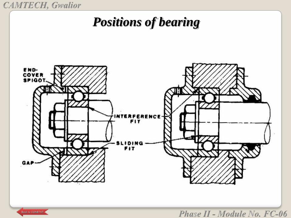
Positions of bearing
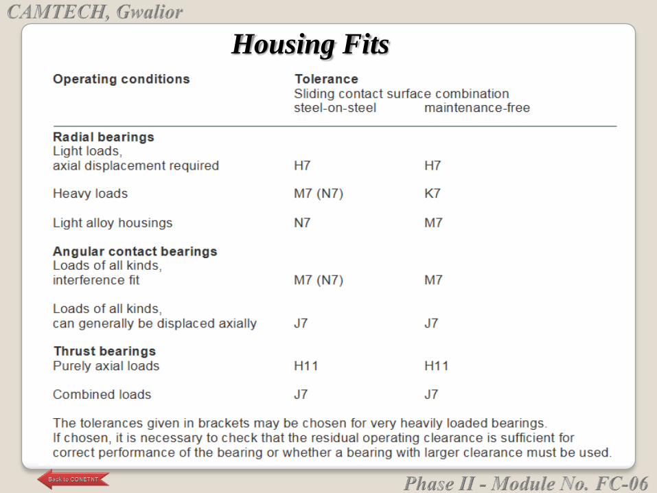
Housing Fits
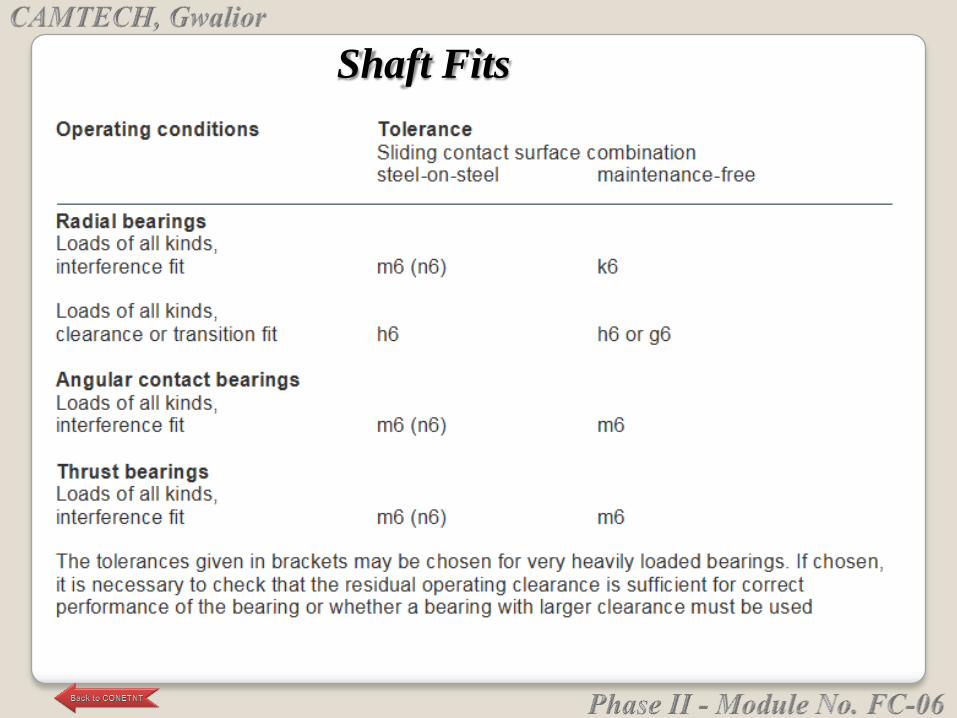
Shaft Fits
Extreme fits, whether loose or tight, are not
recommended. The effect of press fits on contact
angle or radial play must be considered. As a rule of
thumb, mounted radial play (and hence contact
angle) will be reduced by approximately 75% of the
press fit. This is important where precise control on
deflection rates is required or where low-radial-play
bearings are used.
BEARINF FITS
Size tolerance of the shaft and housing should be equal to
those of the bearing bore and OD. Roundness and taper
should be held to one-half of size tolerance. Surface finish
should be held as close as possible.
Extreme fits will depend upon tolerances on the bearings,
shaft, and housing. Upon request, the bearing manufacturer
will code the bearing bores and OD into increments within
the size tolerance. These increments are normally 0.0001 in.,
but can be supplied as low as 0.00005 in.
When operating at a temperature considerably different from
room temperature, material expansion differences must be
considered.
Adhesives offer several advantages in producing
proper fits:
End play can be removed by applying a light
external thrust load during curing time.
Extreme fits can be eliminated, since the adhesive
will fill up any reasonable clearance.
Rotational accuracy can be improved by driving the
shaft at slow speed during cure time. .
Disadvantages to using adhesives include:
Certain adhesives are attacked by lubricants or solvents.
To ensure a good bond, bearing surface, shaft, and
housing must be thoroughly clean of oil and dirt.
Adhesives may get into the bearing and cause damage.
To ensure a good bond without rotational inaccuracies,
clearance should be held reasonably close. The
tolerances on the shaft and housing should be of the
same magnitude as standard-fits practice. Actual
clearance depends upon the specific adhesive.
Under vibration, some adhesives may break loose.
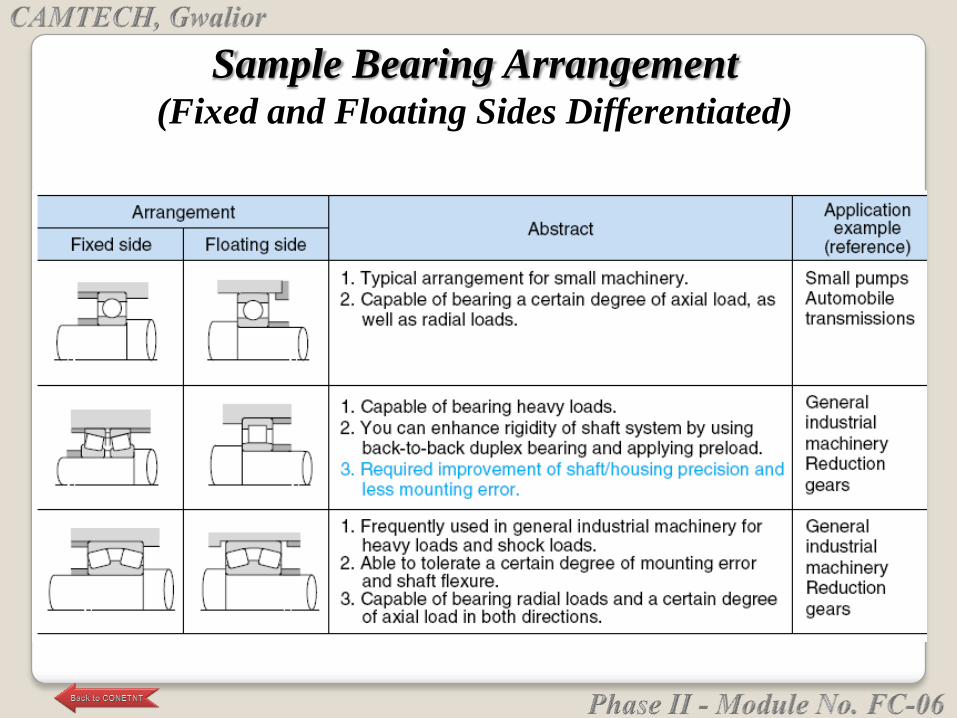
Sample Bearing Arrangement (Fixed and Floating Sides Differentiated)
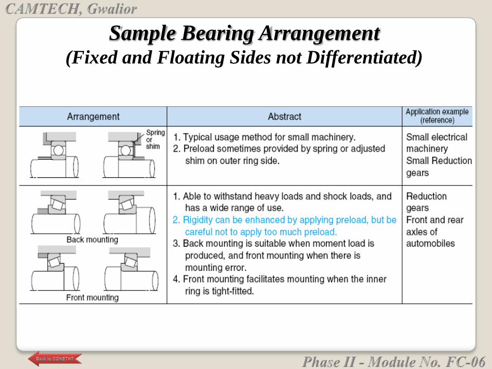
Sample Bearing Arrangement (Fixed and Floating Sides not Differentiated)
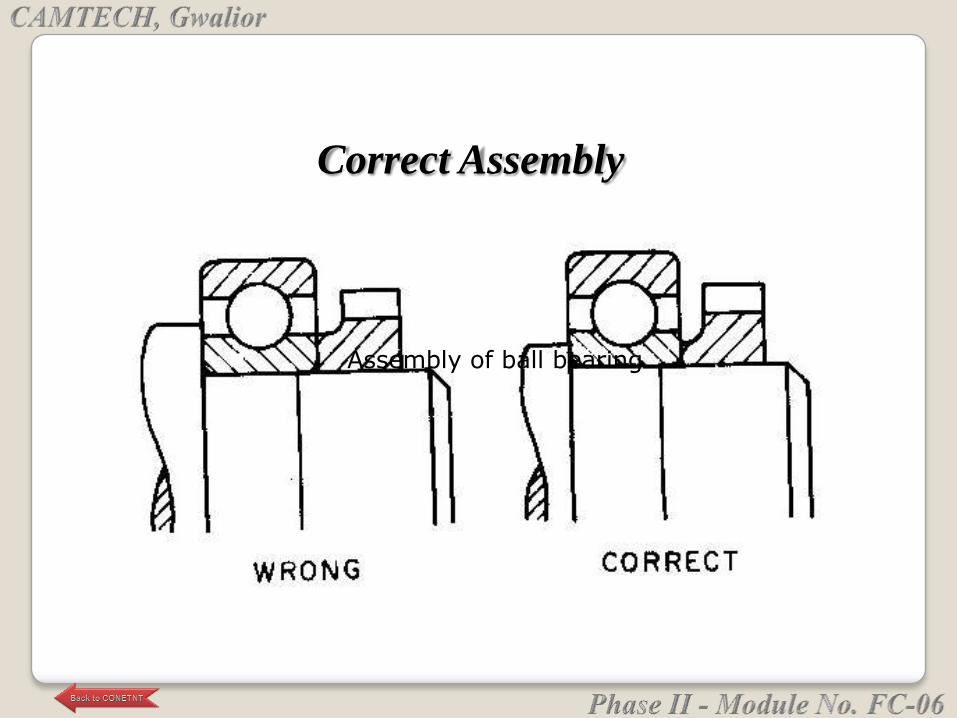
Assembly of ball bearing
Correct Assembly
For instrument bearings, certain special
considerations should be emphasized:
Heavy press fits should be avoided.
Accuracy of mounting surfaces should be equal to
accuracy of mating bearing surface.
Misalignment for low torque and running accuracy
should not exceed 1/4°. Loading across the bearing
during assembly should be avoided.
BEARING MOUNTING
Accurate axial positioning of the shaft relative to the
housing requires shoulders, snap rings, or bearing
flanges.
Shaft and housing shoulders: Diameter of a shaft or
housing shoulder must be sufficient to ensure solid
seating and support for applied thrust loads, yet small
enough to avoid interference with other parts of the
bearing. Most manufacturers provide recommended
shoulder dimensions for each bearing size.
AXIAL POSITIONING
Fit accuracy between shoulder and mounting diameter
should be as good as bearing accuracy.
The corner between the shoulder and mounting
diameter should be undercut because undercutting
provides a more accurate machining of the shoulder
surface. However, a radius is permissible if proper
clearance is allowed.

Retaining rings: Certain cautions must be observed with
this method:
Recommendations as to the groove dimensions should
be followed.
Locating grooves machined into the shaft or housing
must be controlled for squareness of groove face to
bearing mounting diameter. Recommended value is
0.0002-in. TIR max.
Parallelism of the faces of the ring should be held to
0.0002-in. TIR max.
Lug dimensions should be checked to ensure there is
no interference with the bearing. (Extended inner-ring
bearings may offer an advantagehere.)
Avoid a snap ring that locates directly on the shaft or
housing diameter (no groove) if heavy thrust loads are
involved.
Flanges: Squareness of face-to-bore of the housing is
critical and should be maintained to within 0.0003-in.
TIR. Corners may be broken or left sharp because the
flange is undercut and flush seating is ensured.
Removal of excess bearing end play, when required,
may involve preloading of the bearings. However, the
most common requirement is to establish an allowable
range of end play under a given reversing thrust load.
Shims: Best material is stainless steel. Brass shims can
also be used; however, they wear more easily and
produce abrasive particles that could contaminate the
bearing. Shims, particularly brass or other soft materials,
should be used only against the nonrotating ring.
AXIAL ADJUSTMENT

Spring washers: Belleville and wave washers are the
two most common types used. The washer should
exert a very light load on the bearings. If extreme
rigidity under external load is required, preloaded
bearings should be used.
The use of a spring washer usually involves a loose fit
between the bearing ring and its mounting surface.
Therefore, the washer should apply its force against
the non-rotating ring.
Threads: Generally, threads are not recommended to
remove end play. They are too easily overtightened and
can cause brinelling in the bearings.
If threads must be used, the bearings should be locked
against a solid shoulder or spacer. It is important to
achieve a solid locking force without overloading the
bearing rings. A Class 2 fit is normally recommended
because it provides for slight misalignment of the nut,
enabling the nut face to be flush with the bearing. The
nut-face squareness to the thread pitch circle should be
held to 0.0005-in. max wherever possible.
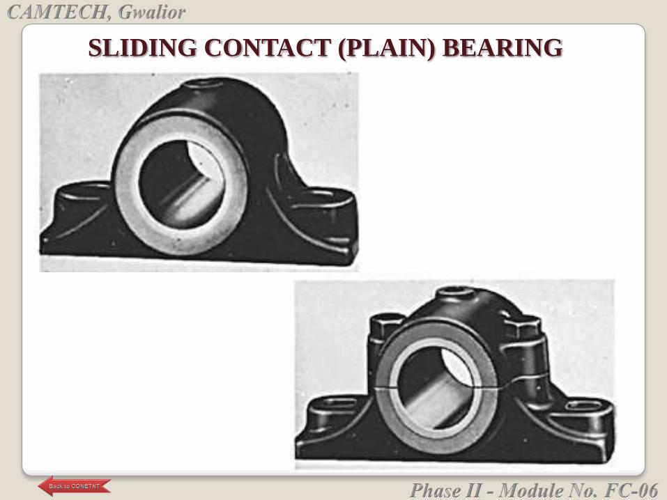
SLIDING CONTACT (PLAIN) BEARING
Collar thrust bearing
Footstep bearingJournal bearing
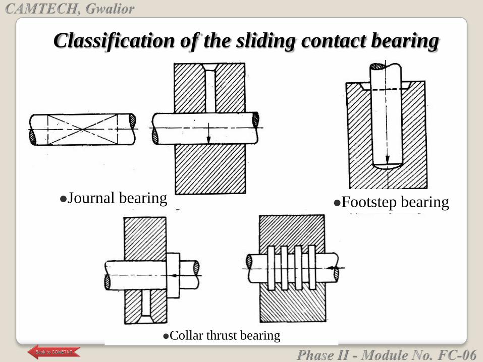
Classification of the sliding contact bearing
Journal bearing
• In this the bearing pressure is exerted at right angles to
the axis of the axis of the shaft. The portion of the
shaft lying within the bearing in known as journal.
Shaft are generally made of mild steel.
Foot step or pivot bearing
• In this bearing the bearing pressure is exerted parallel
to the shaft whose axis is vertical. Note that in this
case the end of the shaft rests within the bearing.
Thrust bearing
• In this bearing supporting pressure is parallel to the
axis of the shaft having end thrust. Thrust bearing are
used in bevel mountings, propeller drives, turbines,
etc. note here the shaft ,unlike foot-strep bearing
passes through and beyond the bearing.
• Thrust bearings also known as ―collar bearing‖.
It is simply a block of cast iron with a hole for the
shaft providing running fit. An oil hole is drilled at
the top for lubrication.
The main disadvantage of this type of bearing are
• There is no provision for wear and adjustment on
account of wear.
• The shaft must be passed into the bearing axially,
i.e. endwise.
• Limited load on shaft and speed of shaft is low.
Simple journal or solid bearing
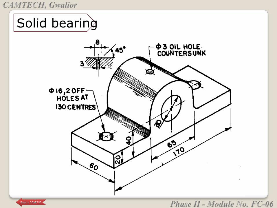
Solid bearing
In this the bush of soft material like brass or gun
metal is provided and the body or main block is
made of cast iron. Bush is hollow cylindrical piece
which is fitted in a housing to accommodate the
mating part. When the bush gets worn out it can
be easily replaced.
Bush bearing
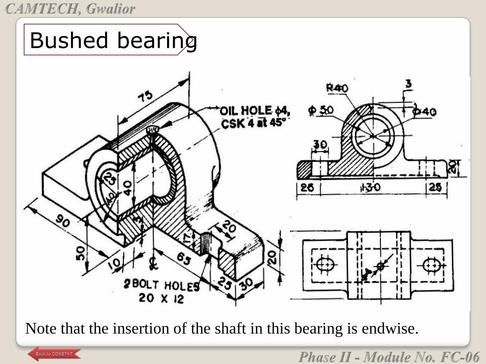
Bushed bearing
Note that the insertion of the shaft in this bearing is endwise.
The outside of the bush is a driving fit (interference
fit) in the hole of the casting where as the inside is a
running fit for the shaft.
The bearing material used may be white metal
(Babbit – Tin/Cu/Lead/antimony) , copper alloy
(brass, gunmetal) or aluminum alloy.
Solid bushes are entirely made of bearing material
and find the general application. In lined bush as the
bearing material is applied as a lining to a backing
material .
Applications: turbines, large diesel engines etc.
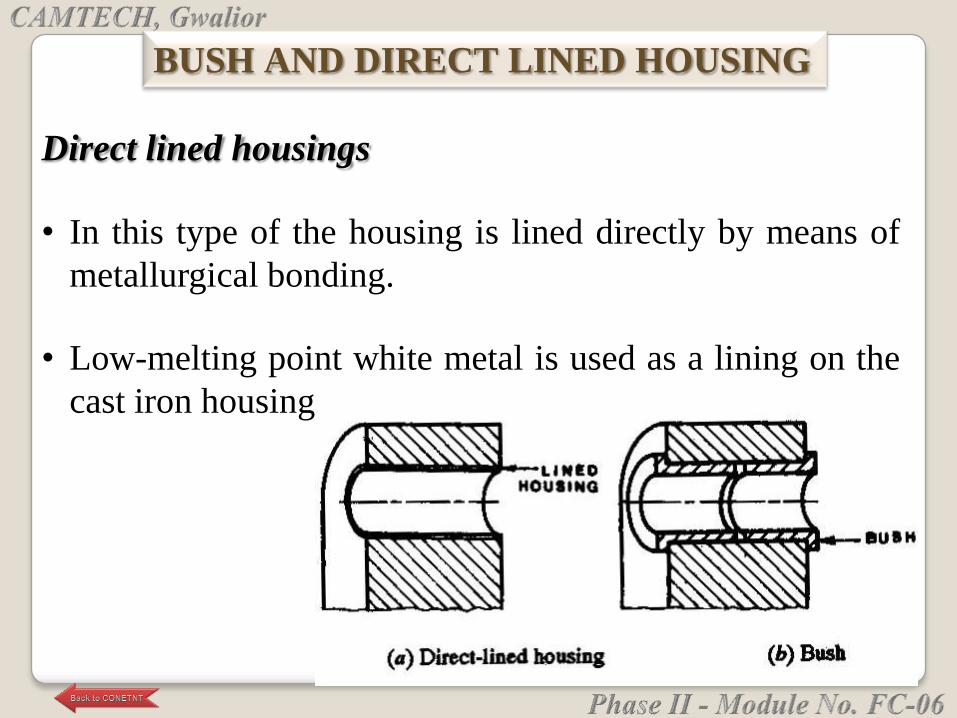
Direct lined housings
• In this type of the housing is lined directly by means of
metallurgical bonding.
• Low-melting point white metal is used as a lining on the
cast iron housing
BUSH AND DIRECT LINED HOUSING
It is a split type of bearing. This type of bearing is
used for higher speeds, heavy loads and large sizes.
The component of the bearing:
• Cast iron pedestal or block with a sole
• Brass or gun-metal or phosphorus-bronze
―Brasses‖, bushes or steps made in two halves.
• Cast iron cap.
• Two mild steel bolts and nuts.
PLUMMER BLOCK AND PEDESTAL BEARING
Care is taken that the brasses do not move axially nor
are allowed to rotate. For preventing this rotation ,
usually a snug at the bottom fitting inside a recess at
the bottom of the pedestal is provided.
This bearing facilitates the placements and removal
of the of the shaft from the bearing. Unlike the solid
bearing which are to be inserted end-wise and hence
are kept near the ends of the shaft, these can be
placed anywhere. This bearing ensures a perfect
adjustment for wear in the brasses by screwing the
cap.
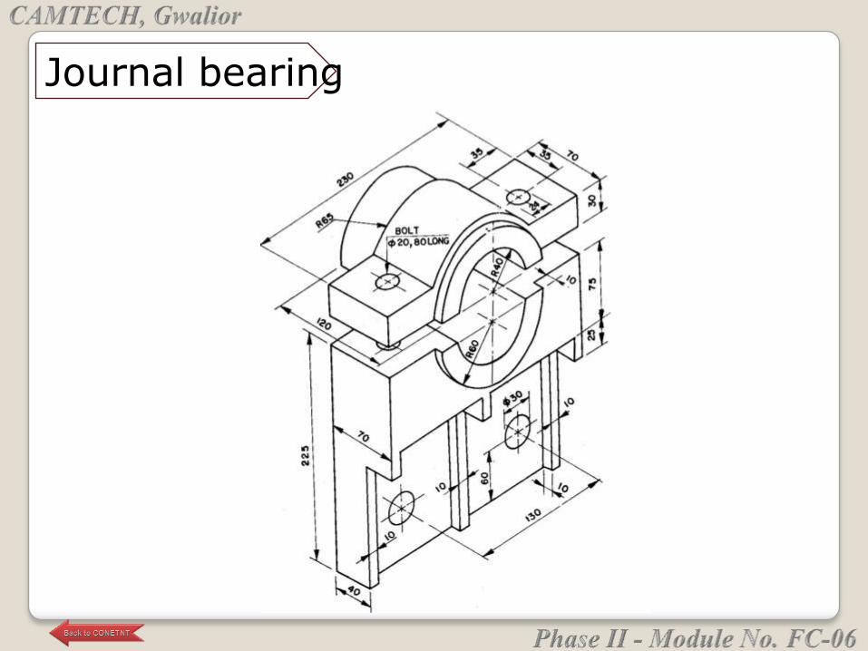
Journal bearing
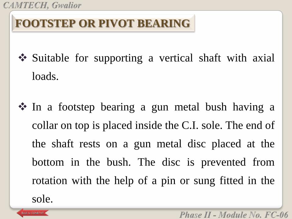
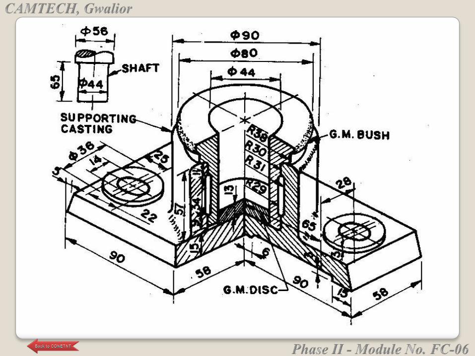
Suitable for supporting a vertical shaft with axial
loads.
In a footstep bearing a gun metal bush having a
collar on top is placed inside the C.I. sole. The end of
the shaft rests on a gun metal disc placed at the
bottom in the bush. The disc is prevented from
rotation with the help of a pin or sung fitted in the
sole.
FOOTSTEP OR PIVOT BEARING
The disc act as a thrust bearing whereas the bush
fitted in the casting supports the shaft in position.
The bush can take radial loads, if any, on the shaft.
The disadvantage of footstep bearing is that it cannot
be efficiently lubricated and there is unequal wear on
the bottom disc.
Plain bearing are cheap to produce and have noiseless
operation. They can be easily machined, occupy small
radial space and have vibration damping properties. Also
they can cope with tapped foreign matter.
Disadvantages are they require large supply of lubricating
oil, they are suitable only for relative low temperature and
speed; and starting resistance is much greater than running
resistance due to slow build up of lubricant film around
the bearing surface.
ADVANTAGES AND DISADVANTAGES OF THE
PLAIN BEARING
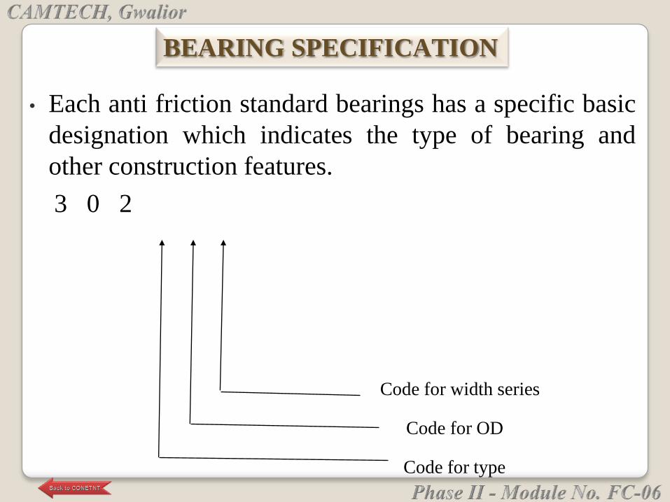
Code for width series
Code for OD
Code for type
• Each anti friction standard bearings has a specific basic
designation which indicates the type of bearing and
other construction features.
3 0 2
BEARING SPECIFICATION
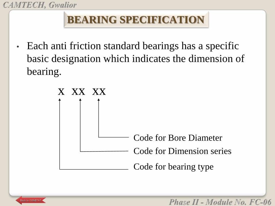
• Each anti friction standard bearings has a specific
basic designation which indicates the dimension of
bearing.
BEARING SPECIFICATION
Code for Bore Diameter
Code for Dimension series
Code for bearing type
x xx xx
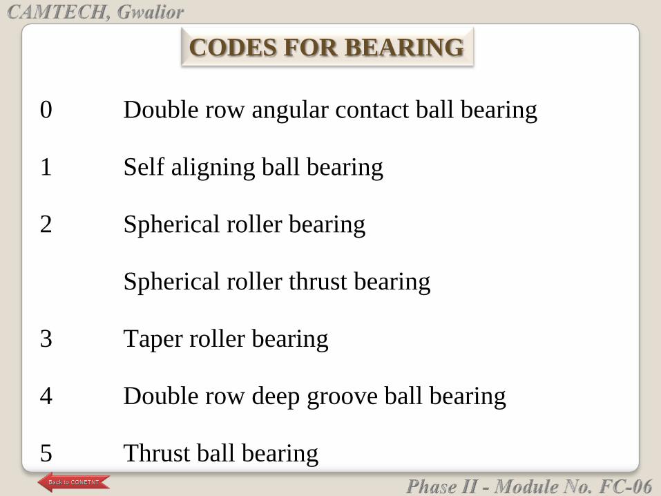
0 Double row angular contact ball bearing
1 Self aligning ball bearing
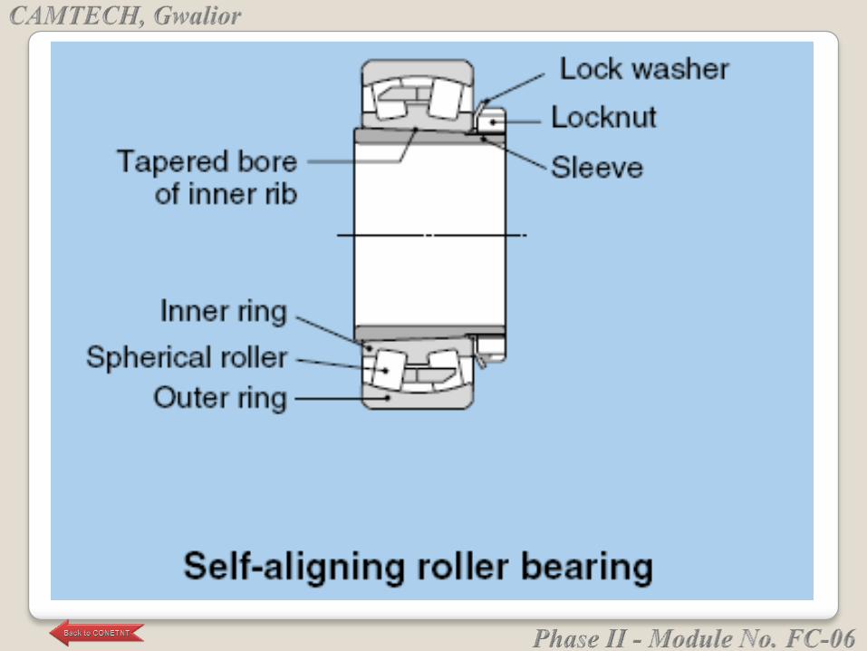
2 Spherical roller bearing
Spherical roller thrust bearing
3 Taper roller bearing
4 Double row deep groove ball bearing
5 Thrust ball bearing
CODES FOR BEARING
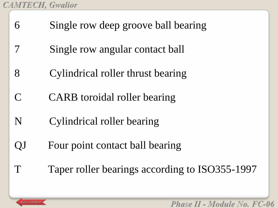
6 Single row deep groove ball bearing
7 Single row angular contact ball
8 Cylindrical roller thrust bearing
C CARB toroidal roller bearing
N Cylindrical roller bearing
QJ Four point contact ball bearing
T Taper roller bearings according to ISO355-1997
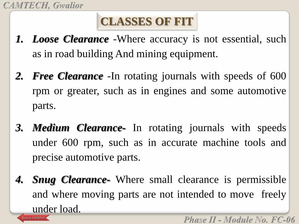
1. Loose Clearance -Where accuracy is not essential, such
as in road building And mining equipment.
2. Free Clearance -In rotating journals with speeds of 600
rpm or greater, such as in engines and some automotive
parts.
3. Medium Clearance- In rotating journals with speeds
under 600 rpm, such as in accurate machine tools and
precise automotive parts.
4. Snug Clearance- Where small clearance is permissible
and where moving parts are not intended to move freely
under load.
CLASSES OF FIT

5. Wringing Interference- Where light tapping with a hammer
is necessary to assemble the parts.
6. Tight Interference- In semi permanent assemblies
suitable for drive of shrink fits on light sect ions.
7. Medium Interference- Where considerable pressure is
needed to assemble and for shrink fits of medium
sections; suitable for press fits on generator and motor
armatures and for car wheels.
8. Heavy force or shrink- Interference Where considerable
bonding between surfaces is required, such as locomotive
wheels and heavy crankshaft disks of large engines.
• Before mounting, all the necessary parts, tool, equipment and
data need to be at hand.
• It is also recommended that any drawings or instruction be
studied to determine the correct order in which to assemble
the various components.
• Housing, shafts, seals and other components of the bearing
arrangement need to be checked to see that they are clean,
particularly any threaded holes, leads or grooves where
remnants of previous machining operation might have
collected.
PREPARATION FOR MOUNTING AND
DISMOUNTING
Depending on the bearing type, and size, mechanical,
thermal and hydraulic methods are used for mounting.
1. Cold Mounting Method.
2. Hot Mounting Method
MOUNTING METHOD
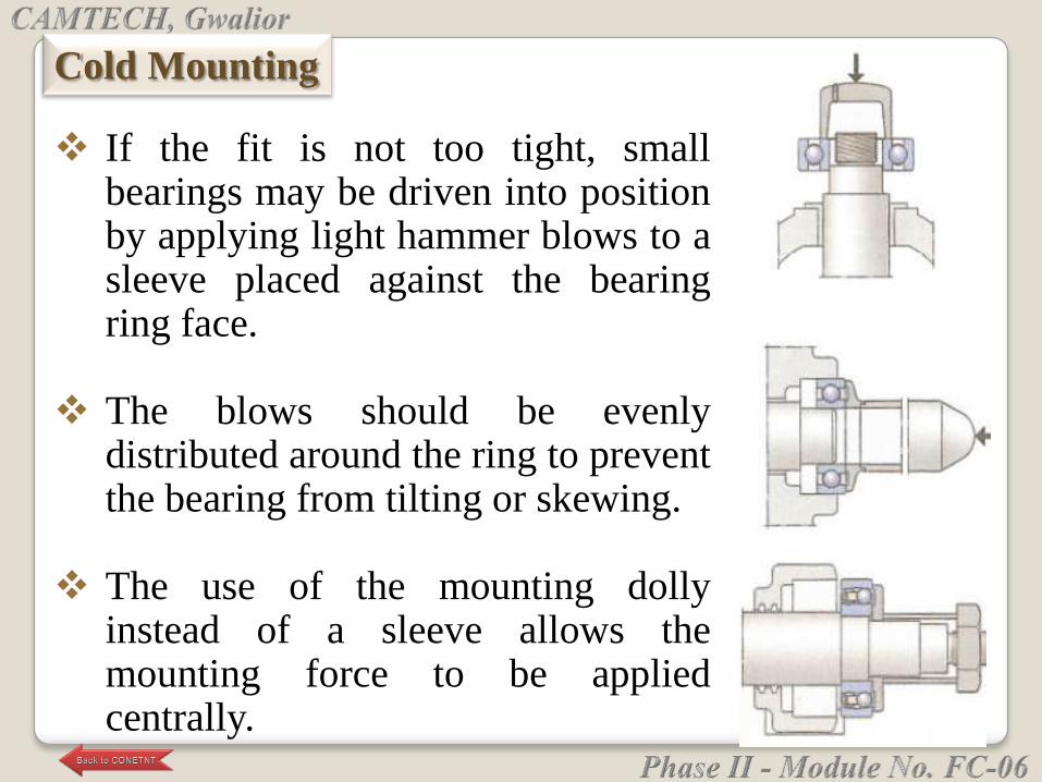
If the fit is not too tight, smallbearings may be driven into positionby applying light hammer blows to asleeve placed against the bearingring face.
The blows should be evenlydistributed around the ring to preventthe bearing from tilting or skewing.
The use of the mounting dollyinstead of a sleeve allows themounting force to be appliedcentrally.
Cold Mounting
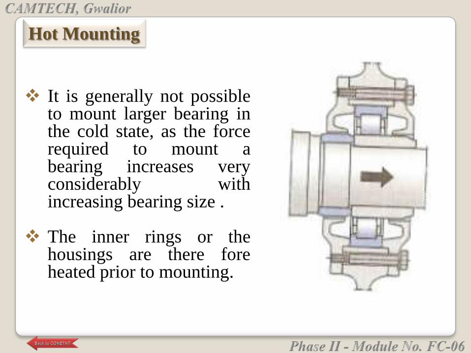
It is generally not possibleto mount larger bearing inthe cold state, as the forcerequired to mount abearing increases veryconsiderably withincreasing bearing size .
The inner rings or thehousings are there foreheated prior to mounting.
Hot Mounting
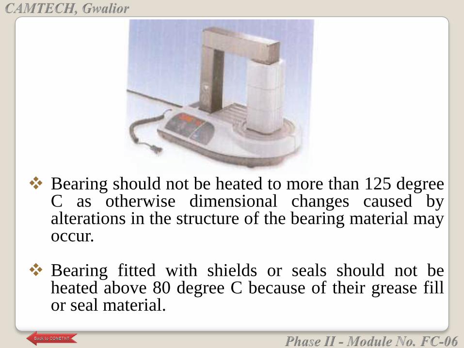
Bearing should not be heated to more than 125 degreeC as otherwise dimensional changes caused byalterations in the structure of the bearing material mayoccur.
Bearing fitted with shields or seals should not beheated above 80 degree C because of their grease fillor seal material.
If the bearings are to be used again after removal, the
force used to dismount them must never be applied
through the rolling elements.
With separable bearings, the ring with the rolling
element and cage assembly can be removed
independently of the other ring.
Dismounting Method
To dismount a bearing having an interference fit, the
tools described in the following section may be used,
the choice of tools will depend on bearing type, size
and fit.
1. Cold dismounting.
2. Hot dismounting.
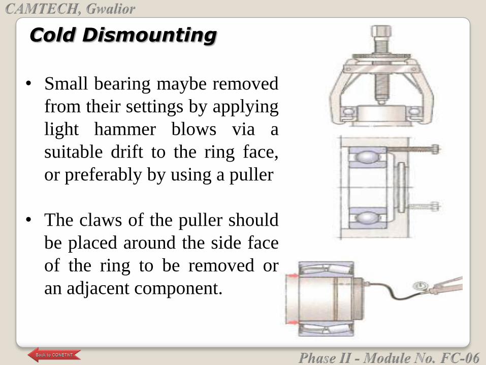
Cold Dismounting
• Small bearing maybe removed
from their settings by applying
light hammer blows via a
suitable drift to the ring face,
or preferably by using a puller
• The claws of the puller should
be placed around the side face
of the ring to be removed or
an adjacent component.
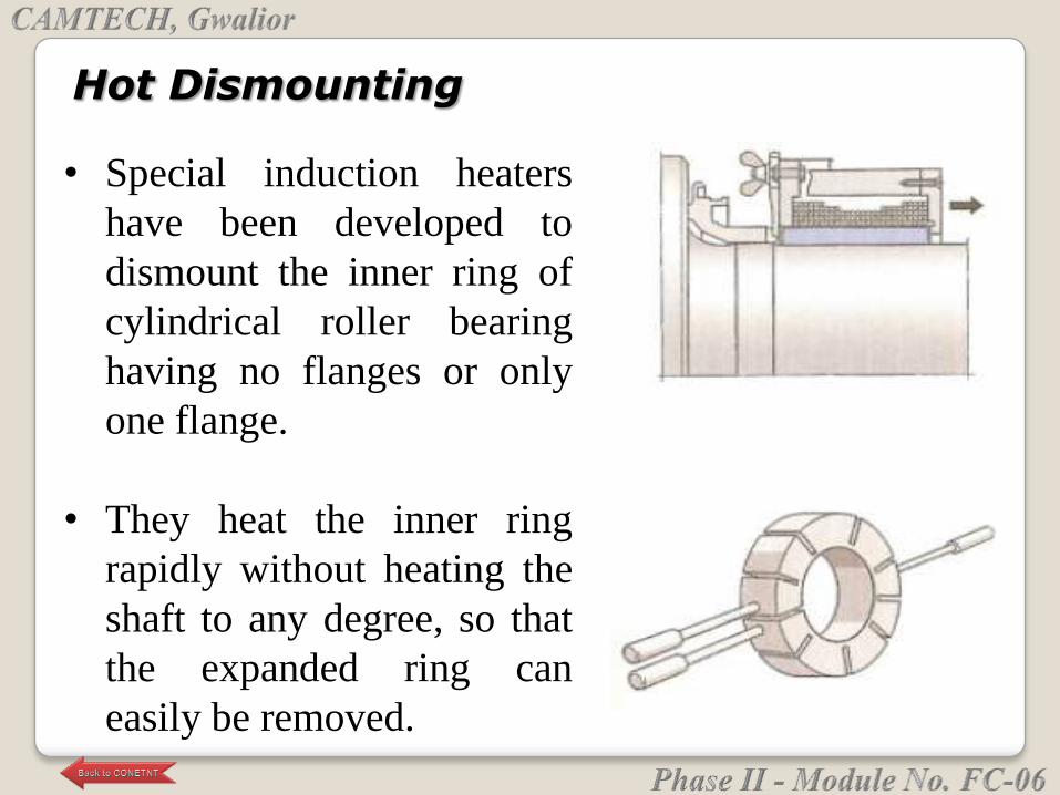
Hot Dismounting
• Special induction heaters
have been developed to
dismount the inner ring of
cylindrical roller bearing
having no flanges or only
one flange.
• They heat the inner ring
rapidly without heating the
shaft to any degree, so that
the expanded ring can
easily be removed.
Lubrication reduces friction. It also prevents wear
and corrosion, and guards against solid and liquid
contamination.
Theoretically, a properly lubricated bearing operating
under ideal conditions will last forever.
This is not possible in reality, of course. But a
properly lubricated bearing has the best chance of
achieving its maximum service life.
Oil and grease require different types of supply systems.
Several oil and grease supply systems exist that meet the
needs of various bearing applications.
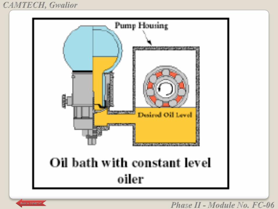
Oil supply systems include: oil baths, circulating oil
systems, spray or mist systems, and the wick feed method.
Grease supply systems include: housings (with or without
grease fittings), grease chamber lubrication, and the grease
quantity regulator.
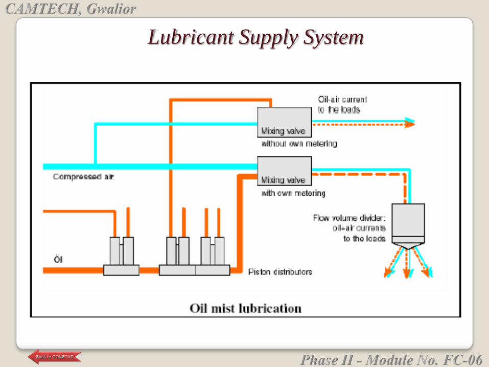
Lubricant Supply System

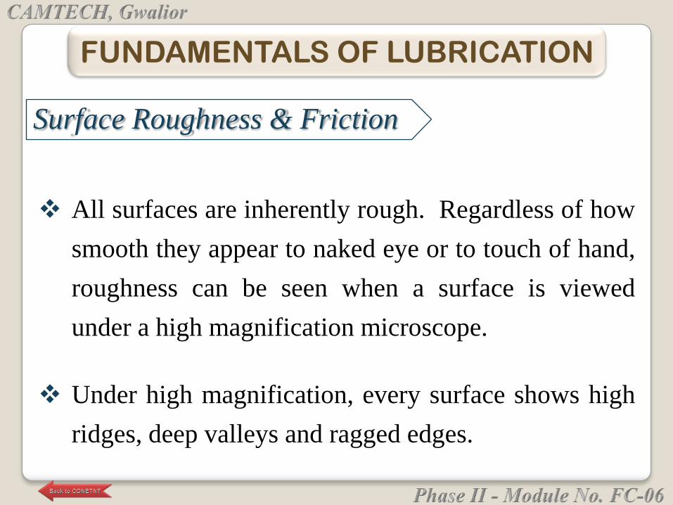
All surfaces are inherently rough. Regardless of how
smooth they appear to naked eye or to touch of hand,
roughness can be seen when a surface is viewed
under a high magnification microscope.
Under high magnification, every surface shows high
ridges, deep valleys and ragged edges.
FUNDAMENTALS OF LUBRICATION
Surface Roughness & Friction
When one body surface slides across another, ridges
& valleys of surfaces slide over one another and
cause resistance to movement, called as Friction.
As force is applied to overcome friction and continue
the motion, high points on mating surfaces come into
contact and start breaking off - producing heat and
wear of surfaces. Minute particles that break off act
as cutting tools and produce grinding action between
mating surfaces, causing more heat & wear.
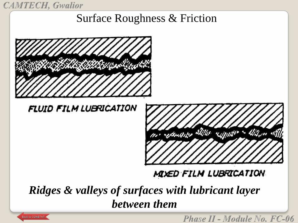
Ridges & valleys of surfaces with lubricant layer
between them
Surface Roughness & Friction
Introducing a suitable substance that separates two
moving surfaces can modify phenomenon of friction,
generation of heat and wear between surfaces. This
process of supporting a sliding surface on a friction-
reducing substance is known as Lubrication and the
substance is called a Lubrication.
WHAT IS LUBRICATION?
Animal and vegetable products were man's first
lubricants. But, because they lack chemical inertness
and because lubrication requirements have become
more demanding, they have been largely superseded
by petroleum products and by synthetic materials.
Some organic substances such as lard and sperm oil
are still in use as additives because of their special
lubricating properties.
a. Reduce Friction:
Lubricant separates two moving surfaces under
load and thus reduces friction.
b. Reduce Wear:
Lubricant reduces wear of both moving and
stationary parts by reducing actual surface contact
between the moving parts or one stationary part
and the other moving part.
FUNCTIONS OF LUBRICANTS
c. Reduce Generation of Heat:
Lubricant reduces friction between the two surfaces
and thus generation of heat.
d. Flush Out Heat:
On account of the flow across two moving surfaces,
lubricants absorb heat and take it away from the
surfaces.
e. Seal out Contaminants:
Lubricant prevents contamination by occupying the
space between contacting surfaces and by
maintaining a positive fluid pressure in the bearing
areas.
f. Flush Out Contaminants:
Flow of lubricant across two moving surfaces
flushes out contaminants.
g. Corrosion protection:
Lubricant prevents entry of other contaminants
and thus protect the surfaces from corrosion.
All liquids provide lubrication of a sort, but some do
it better than others do. For example, Mercury and
Alcohol do not function as lubricants for the
following reasons:
Mercury lacks adhesive & metal wetting
properties that are desirable to keep the lubricant
in intimate contact with the metal surface that it
must protect
LIQUID & SOLID LUBRICANTS
Alcohol on the other hand wets metal surface
readily, but it is too thin to maintain a lubricating
film of adequate thickness.
Solid lubrication: Solids such as graphite and
molybdenum disulfide are widely used when normal
lubricants do not possess sufficient resistance to load
or temperature extremes.
Contd......
Petroleum lubricants are predominantly hydrocarbon products
extracted from Crude Oil that occur naturally within the Earth.
Good quality Base Oils for lubricants can be made from suitable
Crude Oils by refining processes. Such base oils possess a
combination of the following desirable properties:
(1) Oiliness – Metal wetting ability
(2) Suitable Viscosities,
(3) Low Volatility,
(4) Inertness (Resistance To Deterioration),
(5) Corrosion Protection,
(6) Low Cost
MINERAL OILS – LUBRICANTS FROM CRUDE OIL

VISCOSITY of a liquid at certain temperature is
measure of resistance offered by the sliding motion of
one layer of lubricant over an adjacent layer at that
temperature.
• Absolute viscosity of a liquid is defined as the
tangential force on unit area of either one of two
parallel planes at unit-distance apart when space is
filled with that liquid and one of the planes moves
relative to the other with unit velocity in its own
plane.
• The CGS unit of absolute viscosity is the Poise (P).
The centipoise is 1/100th of one Poise.
• Low viscosity lubricating oils are used in journal
bearings subjected to low pressures and high speed
as in bearings of sewing machines, scientific
instruments, centrifuges etc.
• High viscosity lubricating oils are used in bearings
subjected to high pressures and low speeds as in
heavy vehicles.
o Kinematic Viscosity = Absolute Viscosity/
Density
o The unit of Kinematic Viscosity is stokes or
centistoke, which is 1/ 100th of one stoke.
VISCOSITY INDEX (VI) measures the rate at which
viscosity of oil changes with temperature. If viscosity of
oil falls rapidly with an increase in temperature, VI of the
oil is said to be low. On the other hand, if viscosity of
the oil is only slightly affected with an increase in
temperature, its VI is said to be high.
POUR POINT: Lubricating oils containing paraffin
Hydrocarbons tend to form waxy crystals at low
temperatures. Such wax crystals trap liquid oil and keep
it from flowing. The temperature at which this
‗thickening‘ takes place is the Pour Point of the oil. It is
the lowest temperature at which the oil will flow.
• This can be improved by adding additives i.e. Pour Point
depressants. The additives do not entirely prevent wax
crystal growth, but rather lower the temperature at
which a rigid structure is formed.
DETERGENCY AND DISPERCENCY: Engine oils in
service deteriorate & form harmful deposits say behind
piston rings & cause ring sticking, affect clearances &
proper functioning of critical components. Detergents are
those chemical compounds, which chemically neutralise
deposit precursors. Dispersancy is the ability of the oil to
keep these harmful particles in suspension and can be
improved through use of dispersant additives.
ACIDITY: Many lubricants are slightly acidic on
account of some organic compounds. This can cause
corrosion of parts. Acidity increases if lubricant
undergoes oxidation while in service. By oxidation, oil
becomes gummy and cannot flow freely and leads to
sludge formation and corrosion. A good lubricant should,
therefore, not be acidic.
OXIDATION STABILITY: Lubricating oils oxidise in
service as air is inevitably present in lubricating system.
Catalysts particularly Iron and Copper accelerate
oxidation. Oxidation produces acids & sludge, which
affect performance efficiency. Oxidation inhibitors react
with initiators of oxidation to form inactive compounds.
RUST PREVENTION: A good lubricating oil must not
only lubricate but also prevent corrosion during
lubrication of ferrous parts in presence of moisture.
Although this property is important for all oils, it has got
special significance in case of turbine oils. This property
can be improved by adding Anti-rust additives.
EMULSIFICATION: Emulsification is the property of
oils to mix with water forming an intimate mixture called
Emulsion. Emulsion has a tendency to pick up dirt
foreign matter, dust etc. and may result in abrasion and
wear of the surfaces. A good lubricant should not form
an emulsion.
FOAMING: When lubricating oils are churned in the
presence of air, tiny air bubbles are formed. Unless these
bubbles are rapidly released or broken up, persistent foam
of oil and air results. This may cause insufficient
lubrication and eventually lead to bearing or surface
failure. This characteristic can be improved by adding
Antifoam additives.
OILINESS: The ‗Oiliness‘ of a lubricant is its property by
virtue of which the lubricant sticks on to the surface of the
machine part and remain in place even under conditions of
high speed and heavy load. A good lubricant should be
sufficiently oily so that it remains in place and maintain a
continuous film under operating conditions.
FLASH POINT of an oil is the lowest temperature
at which the oil gives off enough vapours, which
ignite for a moment when a small flame is brought
near it.
FIRE POINT of an oil is the lowest temperature at
which the oil gives off enough vapours to burn
continuously for at least five seconds, when a small
flame is brought near it.
Lubricating oils manufactured from crude petroleum
are known as mineral lubricating oils.
Crude petroleum as drawn from the wells is a complex
mixture of following different families of
hydrocarbons boiling at different temperatures and
having different properties:
• Paraffins
• Naphthenes
• Aromatics
Primary grades of lubricating oils known as
‗Lubricating oil base stocks‘ (LOBS) are derived by a
series of refining processes that remove those
constituents that are not suitable as lubricants &
retain those which are suitable.
1. Lubricating oil base stocks are first manufactured
using the following process units:
a) Vacuum Distillation Unit
• Crude oil is first distilled in Crude Distillation Unit
to remove lighter fractions like gas, naphtha,
kerosene and diesel.
• Residue from Crude Distillation Unit is further
distilled under vacuum in Vacuum Distillation Unit
to remove all heavier fractions and obtain Waxy
Distillate, which has fractions with viscosity
suitable for lubricating oils.
b) Solvent Extraction Unit: Aromatic hydrocarbons present
in Waxy Distillate give it a low Viscosity Index. These
are removed from the Waxy Distillate in this Unit.
c) Solvent De-waxing Unit: Waxes present in the Waxy
Distillate give it a high pour point. These waxes are
removed using a suitable solvent so that product from
this unit has suitable pour point.
d) Hydro-finishing Unit: Extracted and de-waxed lube cuts
are hydro-finished to improve the colour stability and
make on-grade lubricating oil base stocks.
2. Lubricating Oil Base Stocks are blended together in
various proportions, with or without additives, to
produce a large variety of Lubricating Oil grades
suitable for specific applications.
• This blending is usually carried out in a lubricating
oil blending plant, which may be either situated
within the Petroleum Refinery or in an Installation
drawing supplies of base oils from one or more
refineries.
Typically, 1 ton of lubricant needs about 0.83 ton of
Lube Oil Base Stock and 0.17 ton of additives.
With additives, lubricating oils are formulated to suit
more than one SAE (Society of Automotive
Engineers) grade. Lubes can, thus, be classified as
single grade or multiple-grade.
Multi grade lubes are superior because of better
physical characteristics.
Additives are used to achieve the following
properties:
• Improvement of Viscosity Index
• Pour point depressants
• Oxidation Stability
• Detergency & Dispersency
Additives get depleted over a period while lubricating
oil is in use on account of interaction with the
environment. It is the depletion of additives, which
limits the useful life of lubricating oils.
Engine oil is composed of a lubricant base stock plus
additives.
Lubricant base stocks from mineral oils have been
categorized into three groups by the API (American
Petroleum Institute).
Group I base stocks are fractionally distilled petroleum
which is further refined with solvent extraction
processes to improve certain properties such as
oxidation resistance and to remove wax.
Group II base stocks are fractionally distilled petroleum
that has been hydro-cracked to further refine and purify it.
Group III base stocks have similar characteristics to
Group II base stocks, except that these have higher
viscosity indexes. Group III base stocks are produced by
further hydro-cracking of Group II base stocks, or of
hydro-isomerized slack wax, (a byproduct of the de-
waxing process).
Typically, 1 ton of lubricant needs about 0.83 tons of Lube
Oil Base Stock and 0.17 tons of additives.
By use of additives it is possible to formulate
lubricating oil, which may fall within the range of
more than one SAE (Society of Automotive
Engineers) grade.
Lubes can, therefore, be classified on the basis of
characteristics as single grade or multiple-grade.
Multi grade lubes are superior because of better
physical characteristics and variety of use.
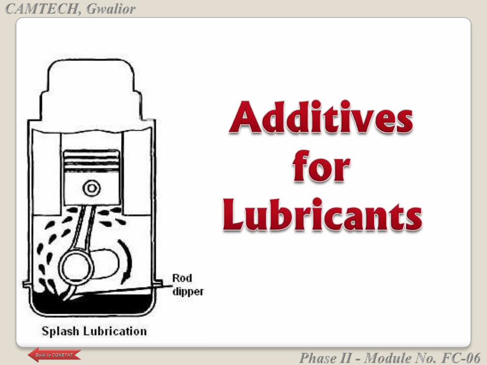
Additives are used to achieve following
properties:
• Improvement of Viscosity Index - Polymeric
substances like poly-butene function as viscosity index
improvers i.e., to reduce the effects of temperatures on
viscosity. These additives make the oil a multi-grade
motor oil.
• like metallic soaps, phenols, poly-methacrylatePour
point depressants s, etc. are used as additives to
increase fluidity at lower temperatures. Lubes,
otherwise, have components, which may solidify at
lower temperatures.
• Oxidation Stability: Lubricants get exposed to
oxygen leading to formation of acids and sludge,
which deteriorate performance. Anti oxidants like
metal phenates, phenols etc. are used as additives to
impart oxidation stability.
• Detergency and Dispersency: Alkaline earth salts are
used as additives to improve the detergency and
dispersency of lubricating oils. These become very
useful to keep the engine parts clean.
• These additives help to disperse oil sludge consisting
products of combustion like carbonaceous particles, sulphur
acids, etc. and prevent them getting deposited on the walls
of the engine.
• Corrosion inhibitors are added as antirust and to limit
extent of corrosion at engine operating temperatures.
• Antifoam and Anti-emulsion additives are added where
presence of water and air is possible. Foaming takes place as
the entrapped air bubbles tend to dislodge from the oil.
Churning of oil with water can lead to formation of
emulsions. Anti-emulsion additives assist in separating
water from oil.
Additives for protection under extreme-pressure
conditions like Zinc dialkyldithiophosphate (ZDDP)
additives, which typically also contain calcium, are
available for heavy duty performance situations.
• ZDDP and calcium additives are also added to protect
engine oil from oxidative breakdown and to prevent the
formation of sludge and varnish deposits. The quantity
of zinc dialkyldithiophosphate is limited to minimize
adverse effect on catalytic converters
Anti-wear additives containing molybdenum disulphide
claim to reduce friction, bond to metals and anti-wear
properties.
Synthetic motor oils have been made from the following
classes of lubricants:
Polyalphaolefin (PAO)
• API (American Petroleum Institute) Group IV base oil
Synthetic esters, etc
• API Group V base oils (non-PAO synthetics, including
diesters, polyolesters, alklylated napthlenes, alkyklated
benzenes, etc.)
• The additives get depleted over a period while the
lubricating oil is in use on account of interaction with the
environment. It is the depletion of additives, which limits
the useful life of lubricating oils.
The Society of Automotive Engineers (SAE): Defines
what is called a "Grade of viscosity" for each
lubricant. SAE has established a numerical code
system for grading motor oils according to their
kinematic viscosity.
For single-grade oils, kinematic viscosity is measured
at a reference temperature of 100 °C in units of mm²/s
or the equivalent older non-SI units, centistokes (cSt).
GRADES OF LUBRICANTS
Based on the range of viscosity, the oil is graded as
SAE number 0, 5, 10, 20, 30, 40, 50, 60 or 70. The
higher the viscosity, the higher the SAE grade
number is. The reference temperature approximates
the operating temperature to which motor oil is
exposed in an engine.
Example: S.A.E. 40 (summer viscosity grade). The
higher the number, the more the oil will preserve
viscosity when subjected to heat.
When the engine is cold, viscosity of oil with no
additives goes up. It is important then that it remain
fluid, in order to flow throughout the engine and aid
in starting. Cold viscosity is stated in S.A.E. norms
by a "winter viscosity grade".
Example: S.A.E.10W The number which signals the
winter viscosity grade is always followed by a "W"
(for "winter"). The smaller the number, the more the
oil will remain fluid in cold weather.
On single-grade oils, viscosity testing is done both at
cold, winter (W) temperature (SAE number 0W, 5W,
10W, 15W, 20W, or 25W) as well as checking
minimum viscosity at 100 °C to grade the oil.
For some applications, Mono-grade oils are generally
used when the running temperatures from cold start
to highest power operation do not vary greatly.
Multi-grade motor oil - Lubricating oil (with no additives) will
have high viscosity when cold and a low viscosity at the
engine‘s operating temperature.
• To bring difference in viscosities closer together, special
polymer additives called viscosity index improvers are
added. These additives make oil a multi-grade motor oil.
• Viscosity of multi-grade oil still varies but not so much as
without additives.
• Multi-grade oils offer a winter and summer grade
simultaneously.
• Example: S.A.E. 10W 40
Where: 10W = winter grade
40 = summer grade
The SAE designation for multi-grade oils includes two
grade numbers
For example 10W- 40 designates a common multi-grade
oil. Historically, the first number associated with the W
(for winter) is not rated at any single temperature.
• The "10W" means that this oil can be pumped by your
engine as well as a single-grade SAE 10 oil can be
pumped. "5W" can be pumped at a lower temperature
than "10W". "0W" can be pumped at a lower
temperature than "5W".
SAE DESIGNATION FOR MULTI-GRADE OILS
The second number, 40, means that the viscosity of
this multi-grade oil at 100 °C operating temperature
corresponds to the viscosity of a single-grade 40 oil at
same temperature.
Lubricant base stocks are categorized into five groups by the API.
Group I base stocks are composed of fractionally distilled
petroleum which is further refined with solvent extraction
processes to improve properties such as oxidation resistance and to
remove wax.
Group II base stocks are composed of fractionally distilled
petroleum that has been hydro-cracked to further refine and purify
it.
Group III base stocks have similar characteristics to Group II base
stocks, except that Group III base stocks have higher viscosity
indexes.
CATEGORIZATION OF LUBRICANT BASE OILS - 1
CATEGORIZATION OF LUBRICANT BASE OILS - 2
Group III base stocks are produced by further hydro-cracking
of Group II base stocks, or of hydro-isomerized slack wax, (a
byproduct of the de-waxing process).
Group IV base stocks are poly-alpha-olefins (PAOs).
Group V is a catch all group for any other synthetic and mineral
base stocks. Examples of group V base stocks include polyol
esters, polyalkylene glycols (PAG oils), and
perfluoropolyalkylethers (PFPAEs).
Groups I, II, and III are sometimes referred to as mineral oils
and groups IV and V as synthetic oils.

Rubber (natural or synthetic) is characterized by
elasticity, water repellence, and electrical resistance.
Natural rubber is obtained from the milky white
fluid called latex, extracted from specific trees;
Synthetic rubbers are produced from unsaturated
hydrocarbons.
In 1730, it was discovered that rubber erases pencil
marks by rubbing - the property from which the
name of the substance is derived.
In 1823 - first commercial application of rubber was
initiated when Charles Macintosh established a plant
for the manufacture of waterproof cloth by treating it
with a solution of rubber in turpentine.
Rainproof cloth is named after him as Macintosh.
• Natural rubber is an elastomer (an elastic polymer) that is
derived from a milky colloidal suspension (latex), found in the
sap of some trees.
• An elastomer is a material that can undergo much more
deformation under stress than most materials and still return to
its previous size without permanent deformation.
• Purified form of natural rubber is the chemical poly-isoprene,
that can also be produced synthetically.
• The term Gum Rubber is also used to describe the tree-derived
Natural Rubber [code NR], and to distinguish it from Synthetic
Rubber [code SR].
The source of latex is the Para rubber tree.
• These trees respond to wounding by producing more
latex.
• Rubber plantations grow largely within a narrow belt
extending about 1100 km on both sides of the equator.
About 99 percent of plantation rubber comes from
South-east Asia.
• The economic life period of rubber trees in
plantations is around 32 years – up to 7 years of
immature phase and about 25 years of productive
phase.
• Plants 1-2 years of age are transplanted in the fields
and allowed to grow. After 4-5 years, they are ready
for tapping latex.
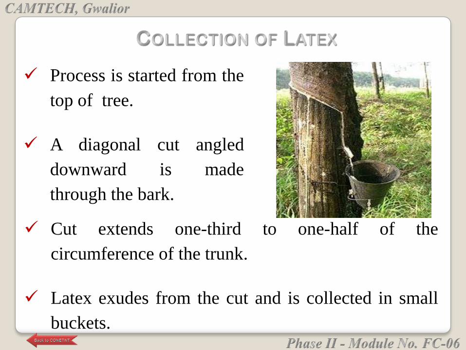
Cut extends one-third to one-half of the
circumference of the trunk.
Latex exudes from the cut and is collected in small
buckets.
Process is started from the
top of tree.
A diagonal cut angled
downward is made
through the bark.
Latex obtained on each tapping is about 30 ml.
Thereafter, a thin strip of bark is shaved from bottom
of original cut to re-tap the tree, usually every other
day.
When the cuttings reach the ground, the bark is
permitted to renew itself before a new tapping round
can be started in a couple of years.
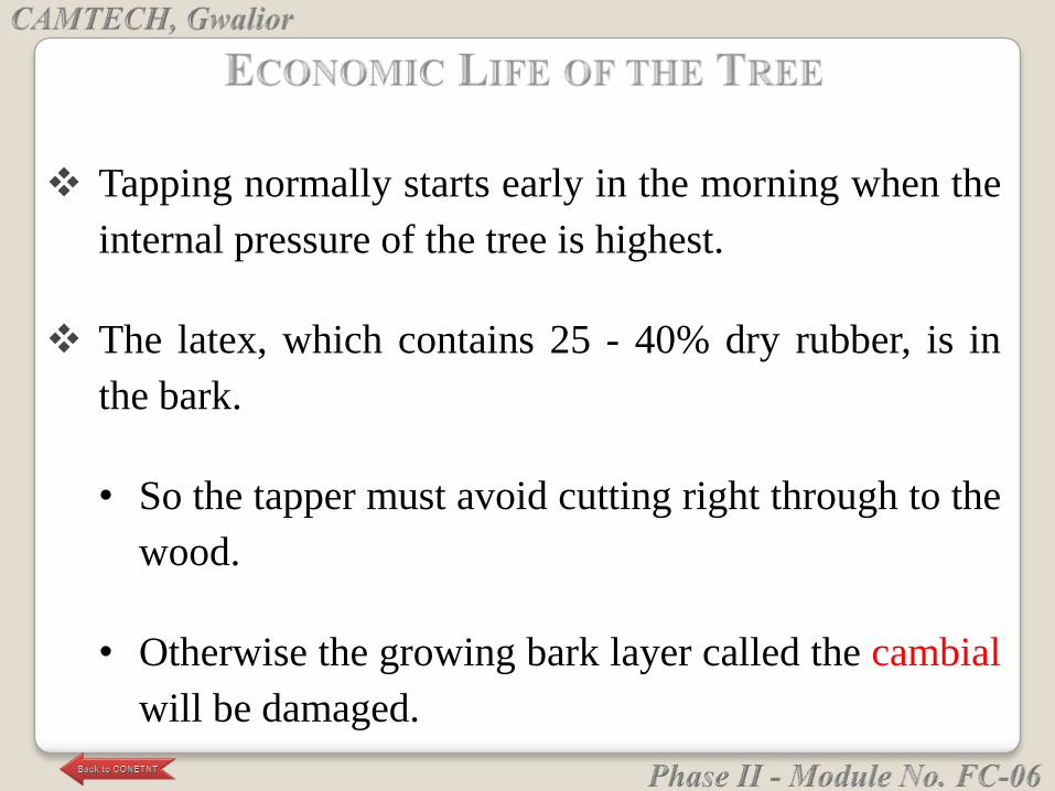
Tapping normally starts early in the morning when the
internal pressure of the tree is highest.
The latex, which contains 25 - 40% dry rubber, is in
the bark.
• So the tapper must avoid cutting right through to the
wood.
• Otherwise the growing bark layer called the cambial
will be damaged.
• And renewing bark will be badly deformed making
later tapping difficult.
The economic life of the tree depends on how well the
tapping is carried out as the critical factor is bark
growth and consumption.
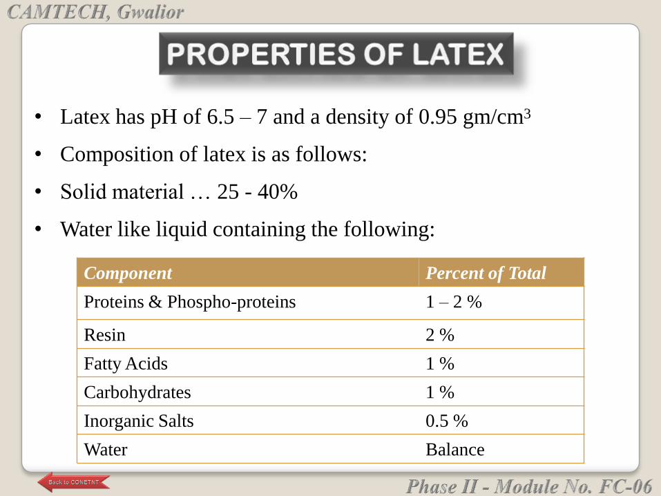
Component Percent of Total
Proteins & Phospho-proteins 1 – 2 %
Resin 2 %
Fatty Acids 1 %
Carbohydrates 1 %
Inorganic Salts 0.5 %
Water Balance
• Latex has pH of 6.5 – 7 and a density of 0.95 gm/cm3
• Composition of latex is as follows:
• Solid material … 25 - 40%
• Water like liquid containing the following:
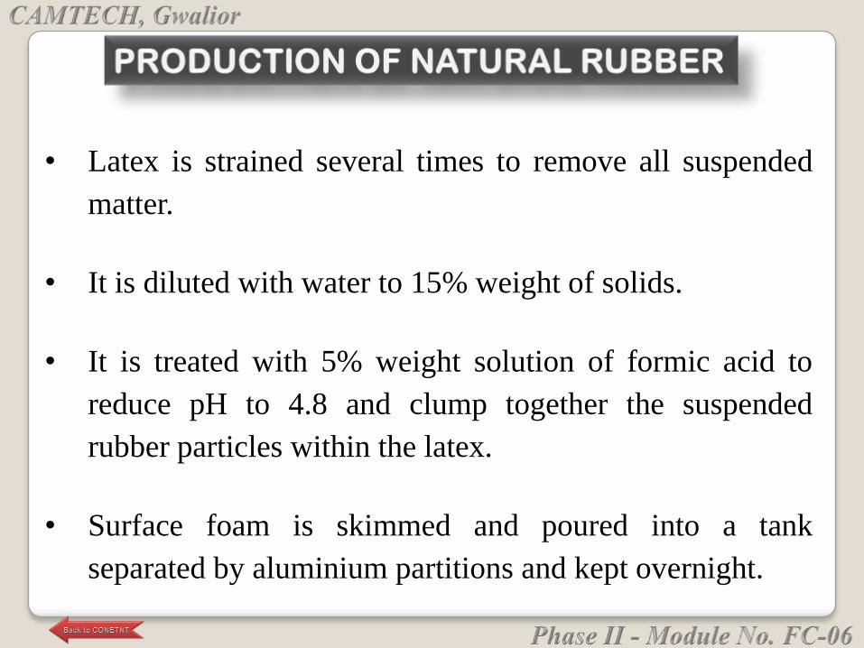
• Latex is strained several times to remove all suspended
matter.
• It is diluted with water to 15% weight of solids.
• It is treated with 5% weight solution of formic acid to
reduce pH to 4.8 and clump together the suspended
rubber particles within the latex.
• Surface foam is skimmed and poured into a tank
separated by aluminium partitions and kept overnight.
• Rubber is obtained by washing coagulum from the
tank. Washing avoids oxidation of rubber.
• Rubber is pressed between rollers to form about 0.6-
cm slabs or thin crepe sheets.
• Rubber is air- or smoke-dried for shipment.
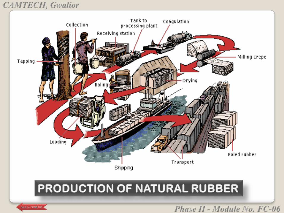

Natural rubber is a whitish material. Chemically analyzed, it
is isoprene (chemical formula C5H8).
It is insoluble in water, alkali & weak acids and soluble in
benzene, chlorinated hydrocarbons, gasoline and carbon
disulfide.
It has poor resistance to heat:
• At 10° C or lower, it is brittle and opaque.
• Around 20° C, it is soft, resilient & translucent.
• Above 50° C, it becomes sticky.
• Above 200° C, it decomposes.
It is oxidized readily by chemical oxidizing agents
and slowly by atmospheric oxygen.
Natural rubber is converted into usable products
through processing & addition of various
ingredients.
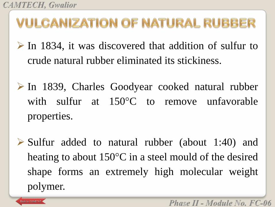
In 1834, it was discovered that addition of sulfur to
crude natural rubber eliminated its stickiness.
In 1839, Charles Goodyear cooked natural rubber
with sulfur at 150°C to remove unfavorable
properties.
Sulfur added to natural rubber (about 1:40) and
heating to about 150°C in a steel mould of the desired
shape forms an extremely high molecular weight
polymer.
• This takes place by joining and cross linking of
isoprene chains
• This process is called Vulcanization (from
Vulcan - the Roman god of fire and metal-
working).
For vulcanizing, Selenium and Tellurium are also
used, but generally with large proportions of sulfur.
Vulcanized rubber has increased strength - higher
than un-vulcanized rubber.
It has higher elasticity and greater resistance to
changes in temperature.
It is impermeable to gases.
It is resistant to abrasion and chemical action of
weak acids and alkalies.
It has good insulation properties both to heat and
electricity.
Vulcanized rubber exhibits high frictional resistance
on dry surfaces and low frictional resistance on
water-wet surfaces.
1) Fillers that stiffen the rubber in the final product, but
that do not materially increase its strength, include
whiting, or calcium carbonate, and barite, or barium
sulfate.
2) Reinforcing fillers add materially to the strength of
the finished product; they include carbon black, zinc
oxide, magnesium carbonate, and various clays.

3) Pigments that give different colors include zinc
oxide, lithopone, and a number of organic dyes.
4) In the hot process of vulcanizing, used for most
rubber goods, the sulfur is ground and mixed with the
rubber at the same time as the other dry ingredients.
The proportion of sulfur to rubber varies from 1:40 in
soft rubber goods to as much as 1:1 in hard rubber.
Masticating Machine: Rubber is made soft, and sticky
in a power-driven variable-pitch screw operating in a
jacketed cylinder. Churning action of the screw on
rubber generates temperatures of around 180° C and
breaks down the rubber.
Mixing Machine: In the mixing machine, there are
rollers that rotate in opposite directions and at
different speeds.
Various fillers, pigments, vulcanizers, and other
compounding ingredients are dry-mixed with
masticated rubber.
After mixing rubber with compounding
ingredients, it undergoes either Calendering or
Extrusion.
Calendering machines consist of three to five rollers
of equal diameter. The speed of rotation and spacing
between the rollers is adjustable.
Calenders are used for producing sheets of rubber with or
without impressed designs such as tire-tread markings.
Extrusion presses force the rubber compound through dies
to form flat, tubular, or specially shaped strips.
Extrusion is used in the manufacture of rubber tubing,
hose, inner tubes, and such stripping as channels for
setting windows or sealing doors.
Specially designed extrusion heads are used for such
processes as coating tubular fabric in making pressure
hose.
Pneumatic tire was invented in 1877.
Shortly, thereafter, American manufacturer Chapman
Mitchell founded a new branch of industry by
introducing acid-reclamation process for scrap
rubber. Scrap rubber was recycled and could be used
to make new products.
This process used hot sulfuric acid to destroy fabric
incorporated in the scrap and heat treatment to
render scrap rubber sufficiently plastic for
incorporation in batches of old rubber.
About 1905 the alkaline-recovery process was
invented by another American chemist Arthur H.
Marks, who also established the first rubber-factory
laboratory.
Alkaline-recovery process permitted the use of large
quantities of reclaimed rubber without seriously impairing
the quality of the finished product.
In 1906, organic accelerators such as aniline and thio-
carbanilide were discovered for vulcanization.
These accelerators not only reduced the heating time
necessary for vulcanization by 60 to 85 percent, but also
increased the quality of the product.

Next great advance in rubber technology came a
decade later when rubber deterioration caused by
exposure to atmospheric oxygen could be measured.
This led scientists to add chemical agents called
antioxidants to rubber which prolonged the useful life
of heavy rubber articles such as automobile tires.
Resistance to abrasion makes softer kinds of rubber
valuable for the treads of vehicle tires and conveyor
belts, and makes hard rubber valuable for pump
housings and piping.
The flexibility of rubber is often used in hose, tires,
and rollers for a wide variety of devices ranging from
domestic clothes‘ wringers to printing presses.

Its elasticity makes it suitable for various kinds of
shock absorbers and for specialized machinery
mountings designed to reduce vibration.
Being relatively impermeable to gases, rubber is
useful in the manufacture of articles such as air hoses,
balloons, balls, and cushions.
The resistance of rubber to water and to the action of
most fluid chemicals has led to its use in rainwear, diving
gear, and chemical and medicinal tubing, and as a lining
for storage tanks, processing equipment, and railroad tank
cars.
Because of their electrical resistance, soft rubber goods
are used as insulation and for protective gloves, shoes,
and blankets; hard rubber is used for articles such as
telephone housings, parts for radio sets, meters, and other
electrical instruments.
The coefficient of friction of rubber, which is high on
dry surfaces and low on wet surfaces, leads to the use
of rubber both for power-transmission belting and for
water-lubricated bearings in deep-well pumps.
Any artificially produced substance that resembles
natural rubber in essential chemical and physical
properties can be called synthetic rubber.
Such substances are produced by chemical reactions,
known as condensation or polymerization of certain
unsaturated hydrocarbons.
The basic units of synthetic rubber are monomers,
which are compounds of relatively low molecular
weight that form the building units of huge molecules
called polymers.
After fabrication, the synthetic rubber is cured by
vulcanization.
The origin of synthetic-rubber technology can be
traced to 1860, when it was determined that natural
rubber was a polymer of the monomer isoprene,
which has the chemical formula CH2:C(CH
3)CH:CH2.
During World War II, supply sources for natural
rubber (Malaysia and elsewhere) were embroiled in
the conflict. To meet the need for rubber, poly-
isoprene was developed.
The properties of poly-isoprene are practically the
same as natural rubber without the need to process
natural rubber to remove impurities.
It is still more economical to use natural rubber.
Thus synthetic poly-isoprene is not as widely used as
natural rubber.
Neoprene: This was one of the first successful synthetic
rubbers developed in 1931.
Neoprene is polymer of monomer chloroprene,
chemical formula CH2:C(Cl)CH:CH2.
The raw materials of chloroprene are acetylene and
hydrochloric acid.
Neoprene has the advantage of high resistance to
heat and such chemicals as oils and gasoline.
Neoprene is, thus, used for:
• Automotive hoses & hoses for conveying
gasoline
• As an insulating material for cables
• General purpose rubber for gaskets, shock
mounts, seals and conveyor belts.
In 1935, the first of a group of synthetic rubbers
called Buna, was produced by copolymerization i.e.
the polymerization of two monomers, called co-
monomers.
Name Buna is derived from initial letters of
butadiene, used as one of the co-monomers, and
natrium (sodium), which was used as a catalyst.
Buna-N (NBR), uses acrylonitrile (CH2:CH(CN)) as
the other co-monomer.
Buna Rubbers
Acrylonitrile is produced from cyanide.
Buna-N is valuable as it does not swell when
immersed in petroleum oils and fuels.
• It is, thus, used for parts requiring resistance to
the action of oils or abrasion like O rings for
seals, fuel pump diaphragms, for petroleum hoses
and gaskets.
The basic rubber produced by the present-day
synthetic-rubber industry is Styrene Butadiene
Rubber (known as Buna S). It is a copolymer of
butadiene and styrene.
Various grades of Buna S are classified in two
categories, regular and cold, depending on the
temperatures of copolymerization.
Cold Buna S types, which exhibit superior
properties, are prepared at 5° C.
Styrene Butadiene Rubbers
Cold buna S is used to make longer-wearing tires
for automobiles and trucks.
Regular Buna S types are prepared at temperatures
of 50° C.
Due to its low cost, it is used for hoses, belts,
gaskets, shock mounts and most auto tires.
This rubber is similar to natural rubber in its properties.
It is a straight chain elastomer polymerized from its
monomer Butadiene (CH2:CH-CH:CH2).
Poly-butadiene is more costly to process into shapes than
rubbers such as SBR.
For this reason, it is often used as an additive up to 75%.
The addition of poly-butadiene improves the hysteresis
and tear resistance of resultant rubbers.
Poly Butadiene Rubbers
Butyl rubber is prepared by copolymerization of
isobutylene with butadiene or isoprene.
It is plastic and can be compounded like natural
rubber, but is difficult to vulcanize.
Chlorine added to butyl rubber (chloro-butyl rubber)
aids heat resistance and processibility.
Butyl Rubber
Although butyl rubber has poor oil resistance and not
as resilient as other synthetics, it is extremely
resistant to oxidation and the action of corrosive
chemicals.
Because of its very low permeability to gas, and
excellent resistance to ageing and ozone, butyl rubber
is used widely for inner plies in puncture-proof tires,
as well as for inner tubes in automobile tires.
Ethylene propylene rubber (EPM) is a copolymer of
polyethylene and polypropylene.
The addition of poly-butadiene to EPM creates EPDM rubber
(ethylene propylene diene monomer)
Both of these rubber families offer exceptional aging and
weathering resistance, excellent electrical properties and good
heat resistance.
Both rubbers are widely used for wire insulation, conveyor
belts and other outdoor applications.
Like butyl rubber, they are not resistant to petroleum oils and
this limits their use in automotive applications.
EPM and EPDM Rubber
Many other synthetic rubbers have been developed
with specific properties. One such specialty rubber,
called Koroseal, is a polymer of vinyl chloride
(CH2:CHCl).
Koroseal cannot be vulcanized, but, when not
subjected to high temp, it is more resistant to abrasion
than natural rubber or leather.
Koroseal is heat, electricity, and corrosion-resistant
and unaffected by exposure to light or by long storage.
Other Specialty Rubbers
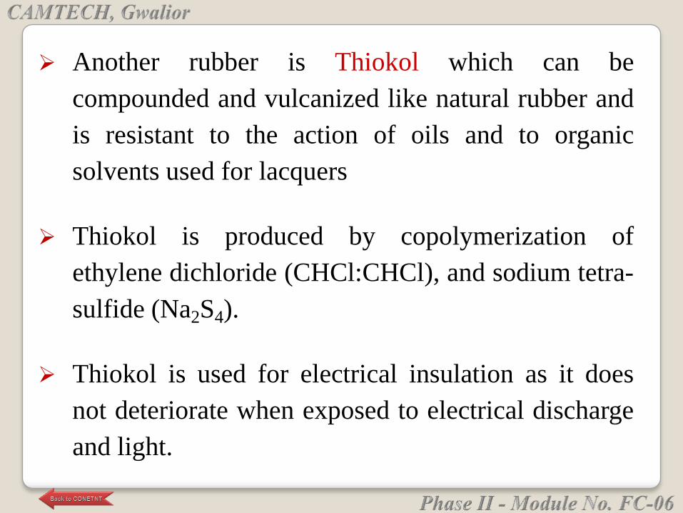
Another rubber is Thiokol which can be
compounded and vulcanized like natural rubber and
is resistant to the action of oils and to organic
solvents used for lacquers
Thiokol is produced by copolymerization of
ethylene dichloride (CHCl:CHCl), and sodium tetra-
sulfide (Na2S4).
Thiokol is used for electrical insulation as it does
not deteriorate when exposed to electrical discharge
and light.
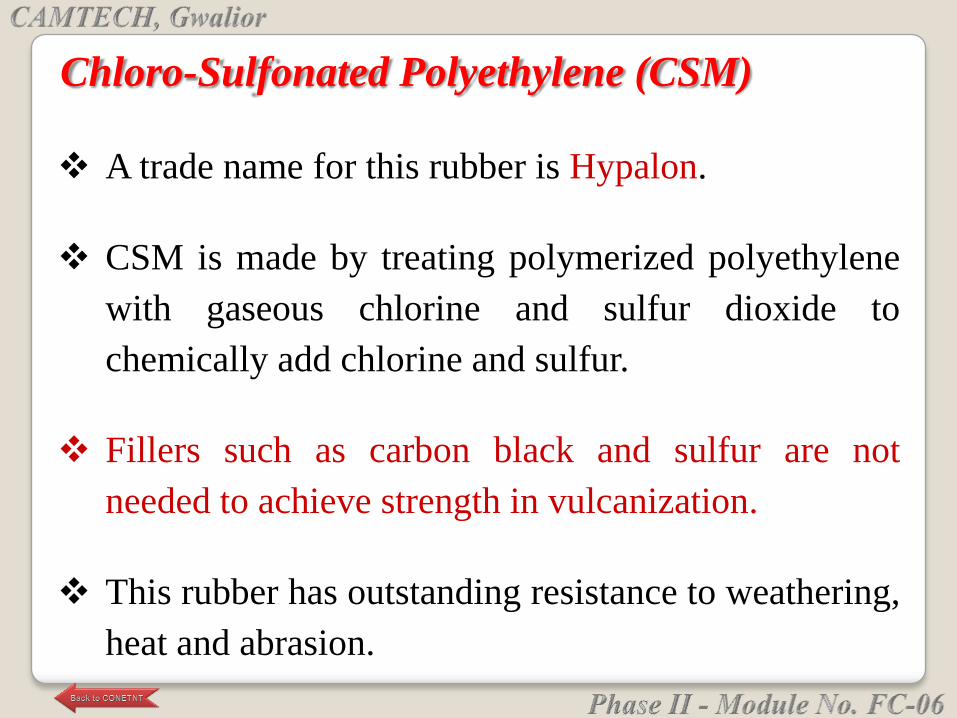
A trade name for this rubber is Hypalon.
CSM is made by treating polymerized polyethylene
with gaseous chlorine and sulfur dioxide to
chemically add chlorine and sulfur.
Fillers such as carbon black and sulfur are not
needed to achieve strength in vulcanization.
This rubber has outstanding resistance to weathering,
heat and abrasion.
Chloro-Sulfonated Polyethylene (CSM)
It is considered to be a high-performance elastomer
rather than a general-purpose rubber.
It is used for high-voltage electrical insulation and in
many chemical plant applications such as tank liners
and pond liners.
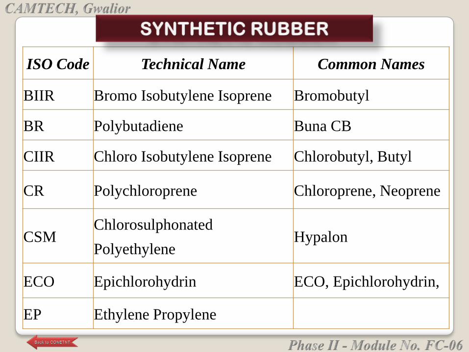
ISO Code Technical Name Common Names
BIIR Bromo Isobutylene Isoprene Bromobutyl
BR Polybutadiene Buna CB
CIIR Chloro Isobutylene Isoprene Chlorobutyl, Butyl
CR Polychloroprene Chloroprene, Neoprene
CSMChlorosulphonated
PolyethyleneHypalon
ECO Epichlorohydrin ECO, Epichlorohydrin,
EP Ethylene Propylene
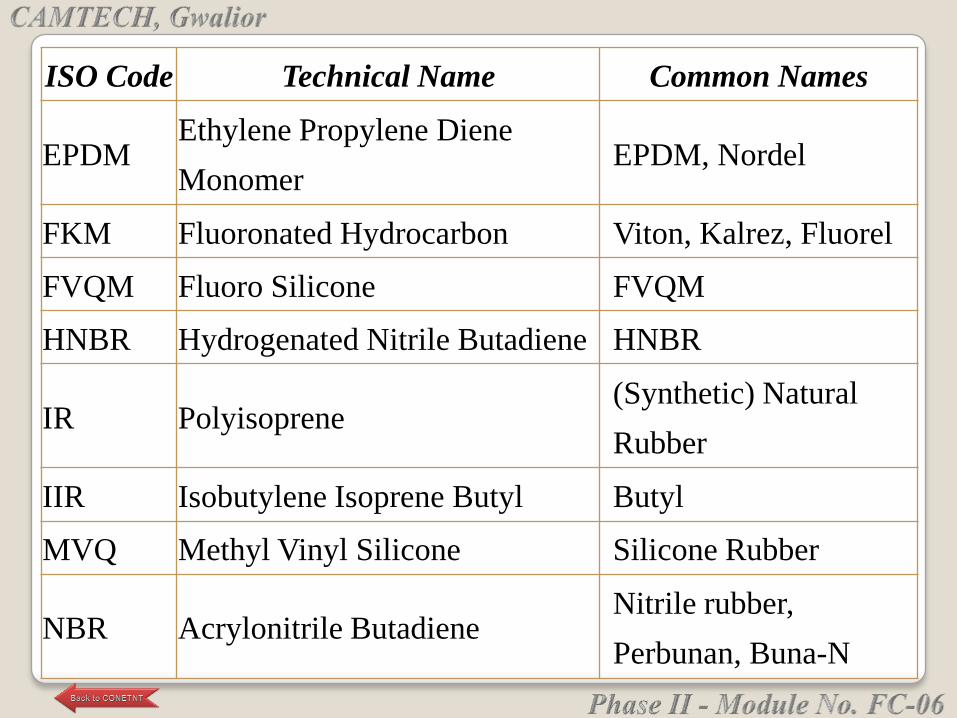
ISO Code Technical Name Common Names
EPDMEthylene Propylene Diene
MonomerEPDM, Nordel
FKM Fluoronated Hydrocarbon Viton, Kalrez, Fluorel
FVQM Fluoro Silicone FVQM
HNBR Hydrogenated Nitrile Butadiene HNBR
IR Polyisoprene(Synthetic) Natural
Rubber
IIR Isobutylene Isoprene Butyl Butyl
MVQ Methyl Vinyl Silicone Silicone Rubber
NBR Acrylonitrile ButadieneNitrile rubber,
Perbunan, Buna-N
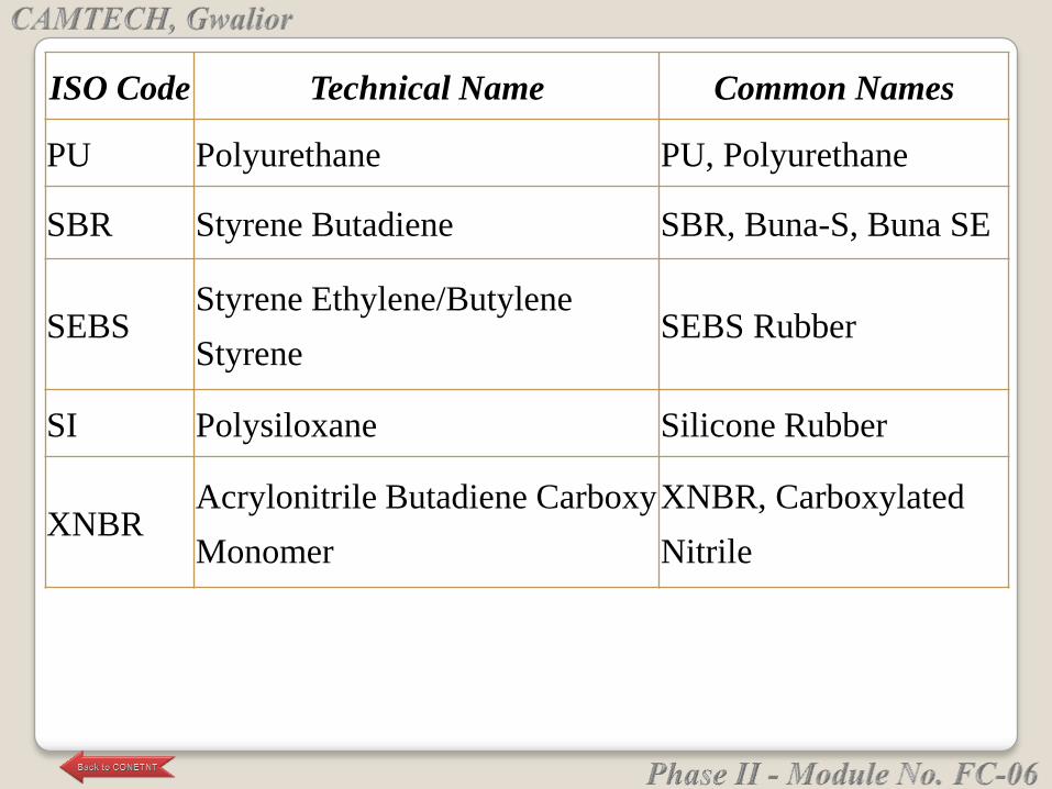
ISO Code Technical Name Common Names
PU Polyurethane PU, Polyurethane
SBR Styrene Butadiene SBR, Buna-S, Buna SE
SEBSStyrene Ethylene/Butylene
StyreneSEBS Rubber
SI Polysiloxane Silicone Rubber
XNBRAcrylonitrile Butadiene Carboxy
Monomer
XNBR, Carboxylated
Nitrile
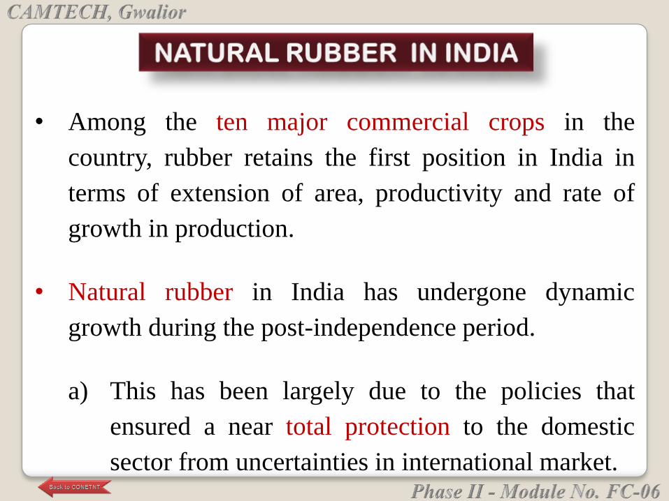
• Among the ten major commercial crops in the
country, rubber retains the first position in India in
terms of extension of area, productivity and rate of
growth in production.
• Natural rubber in India has undergone dynamic
growth during the post-independence period.
a) This has been largely due to the policies that
ensured a near total protection to the domestic
sector from uncertainties in international market.
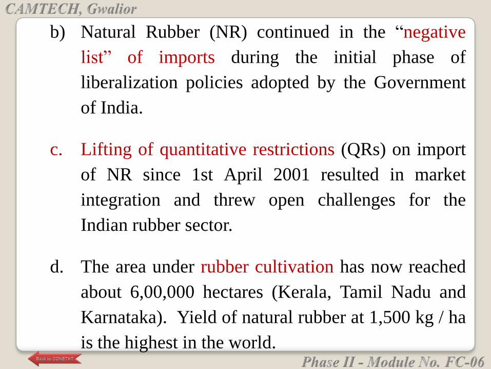
b) Natural Rubber (NR) continued in the ―negative
list‖ of imports during the initial phase of
liberalization policies adopted by the Government
of India.
c. Lifting of quantitative restrictions (QRs) on import
of NR since 1st April 2001 resulted in market
integration and threw open challenges for the
Indian rubber sector.
d. The area under rubber cultivation has now reached
about 6,00,000 hectares (Kerala, Tamil Nadu and
Karnataka). Yield of natural rubber at 1,500 kg / ha
is the highest in the world.
c. Natural Rubber is essentially consumed in the
domestic market and the industry has been
earning foreign exchange by exporting rubber
products.
d. It is reported that using bitumen treated with
natural rubber in making of roads can go to
increase the life of the roads by 50 to 100 %.
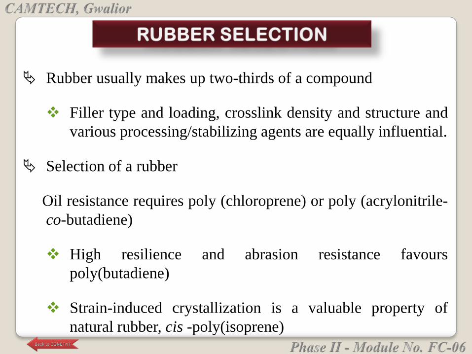
Rubber usually makes up two-thirds of a compound
Filler type and loading, crosslink density and structure and
various processing/stabilizing agents are equally influential.
Selection of a rubber
Oil resistance requires poly (chloroprene) or poly (acrylonitrile-
co-butadiene)
High resilience and abrasion resistance favours
poly(butadiene)
Strain-induced crystallization is a valuable property of
natural rubber, cis -poly(isoprene)
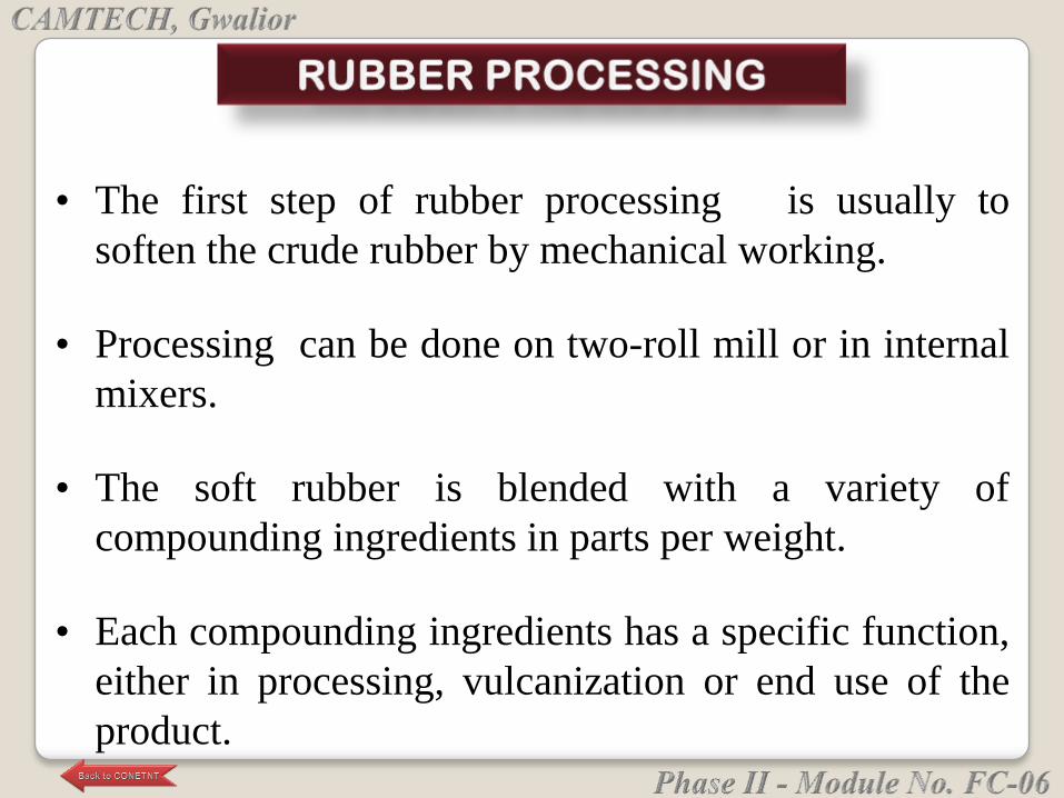
• The first step of rubber processing is usually to
soften the crude rubber by mechanical working.
• Processing can be done on two-roll mill or in internal
mixers.
• The soft rubber is blended with a variety of
compounding ingredients in parts per weight.
• Each compounding ingredients has a specific function,
either in processing, vulcanization or end use of the
product.
• After all compounds have been properly mixed, the
compounded green stock is formed.
• The green stock is converted to an elastic material by
vulcanization.
• The vulcanization is carried under pressure at elevated
temperature.
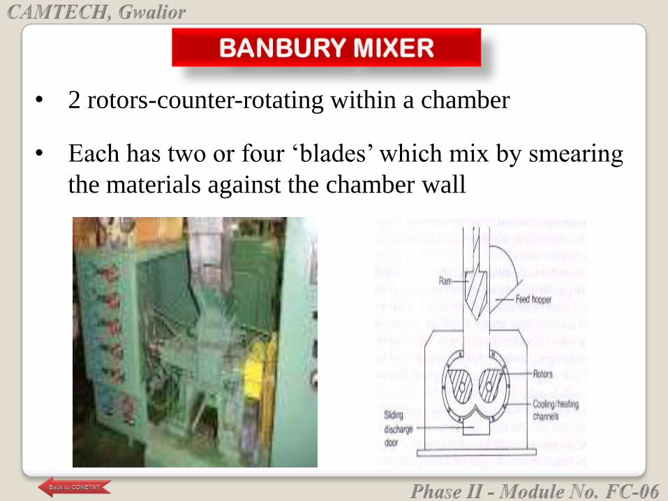
• 2 rotors-counter-rotating within a chamber
• Each has two or four ‗blades‘ which mix by smearing
the materials against the chamber wall
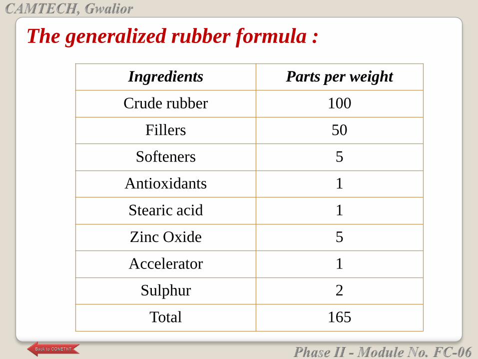
The generalized rubber formula :
Ingredients Parts per weight
Crude rubber 100
Fillers 50
Softeners 5
Antioxidants 1
Stearic acid 1
Zinc Oxide 5
Accelerator 1
Sulphur 2
Total 165
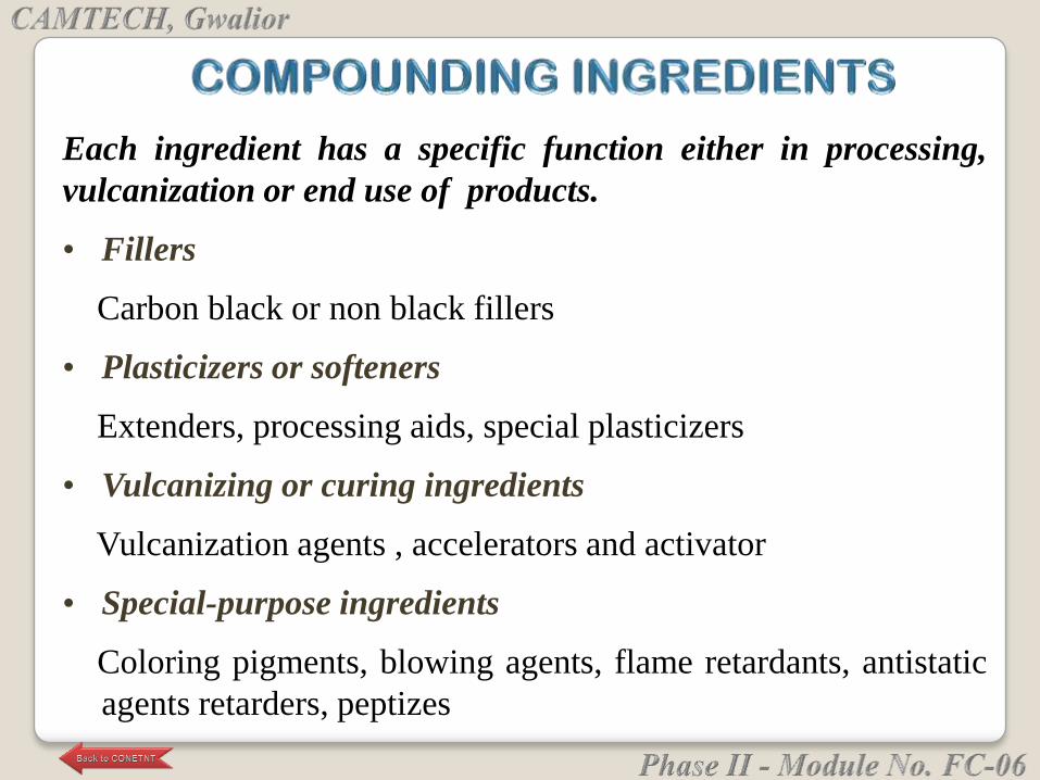
Each ingredient has a specific function either in processing,
vulcanization or end use of products.
• Fillers
Carbon black or non black fillers
• Plasticizers or softeners
Extenders, processing aids, special plasticizers
• Vulcanizing or curing ingredients
Vulcanization agents , accelerators and activator
• Special-purpose ingredients
Coloring pigments, blowing agents, flame retardants, antistatic
agents retarders, peptizes
Fillers
Carbon blacks consists mainly of finely divided carbon
manufactured by incomplete combustion of natural gas
or petroleum (ASTM D1765)
• The non-black fillers include clays, calcium
Carbonate silicates& precipitated and (anhydrous )
silica's.
• Fillers are added for economic (cost ) or technical
reasons (reinforcement ).
• Reinforcement means enhancement of properties such
as tensile strength, tear & abrasion resistance.
Plasticizers or softeners can be liquids, semi- solids or
solids.
• They must be compatible with the crude rubber &
other compounding ingredients.
• Petroleum oils are the most widely used extenders &
processing aids.
• A large amount ( above 20 phr ) may act as an
extenders & a small amount ( 2-5 phr ) as a processing
aid.
Plasticizers

• Age resistors or anti-degradants are organic substances
added in small mounts (about 1-4 phr) to retard
deterioration caused by aging.
• Anti-oxidants primarily protect the elastomer against
oxidation & heat.
• Anti-ozonants retards or prevent the appearance of
surface cracks caused by .
• Anti-flex cracking agents retards cracking caused by
cyclic deformation.
Age Resistors
• Coloring pigments are substances are added for
coloring non-black rubber goods.
• The inorganic pigments (such as titanium dioxide,
lithopone & red iron oxides) are stable to heat &
light.
• Organic pigments (such as compounds) produce
bright colors & intense coloration is achieved.
• Retarders are substances used to reduce the tendency
of a rubber mix to scorch.
Special Purpose Ingredients
Reinforcing Filler Selection
• Particle Size
The most important filler characteristic is particle
size, which determines the surface area per gram.
Typical reinforcing fillers have diameters from
20-300 nm.
Surface areas vary from 6 m2/g to 250 m2/g for
different grades of carbon black.
• Surface Activity
The adsorptive capacity of a filler for the polymer
phase varies amongst different classes (carbon black,
silica, ZnO, clays)
Dispersion of filler within the matrix requires
physical adsorption
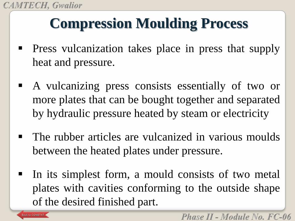
Compression Moulding Process
Press vulcanization takes place in press that supply
heat and pressure.
A vulcanizing press consists essentially of two or
more plates that can be bought together and separated
by hydraulic pressure heated by steam or electricity
The rubber articles are vulcanized in various moulds
between the heated plates under pressure.
In its simplest form, a mould consists of two metal
plates with cavities conforming to the outside shape
of the desired finished part.
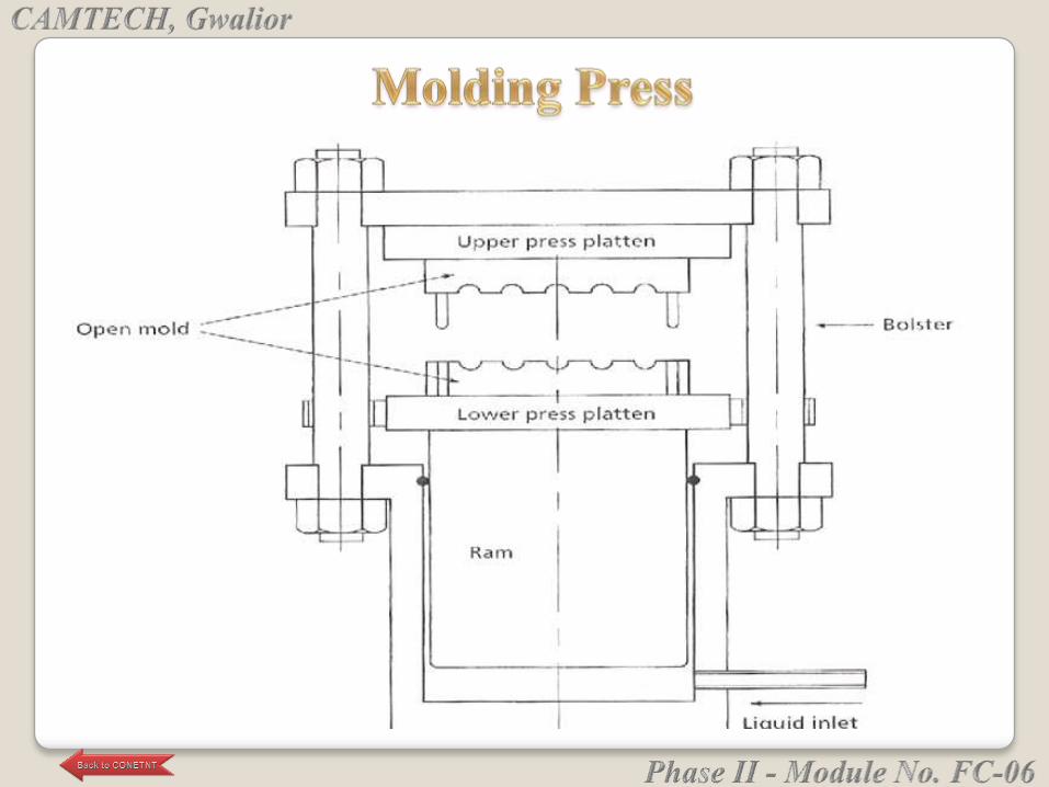
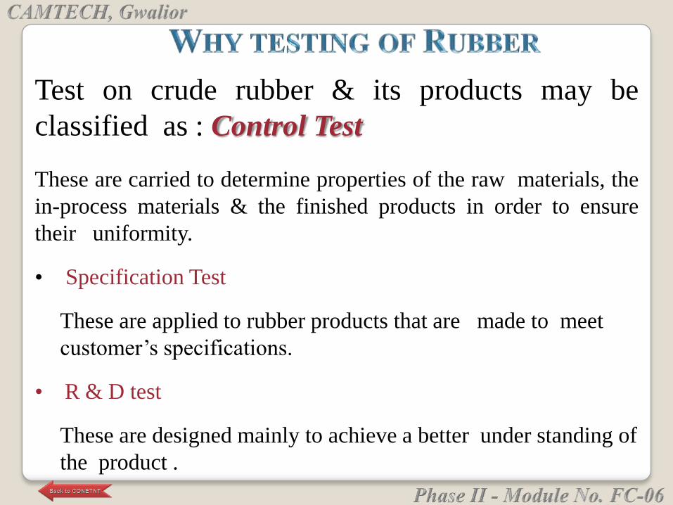
Test on crude rubber & its products may be
classified as : Control Test
These are carried to determine properties of the raw materials, the
in-process materials & the finished products in order to ensure
their uniformity.
• Specification Test
These are applied to rubber products that are made to meet
customer‘s specifications.
• R & D test
These are designed mainly to achieve a better under standing of
the product .
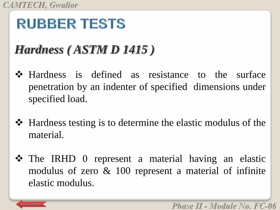
Hardness ( ASTM D 1415 )
Hardness is defined as resistance to the surface
penetration by an indenter of specified dimensions under
specified load.
Hardness testing is to determine the elastic modulus of the
material.
The IRHD 0 represent a material having an elastic
modulus of zero & 100 represent a material of infinite
elastic modulus.

Shore A Hardness Tester363
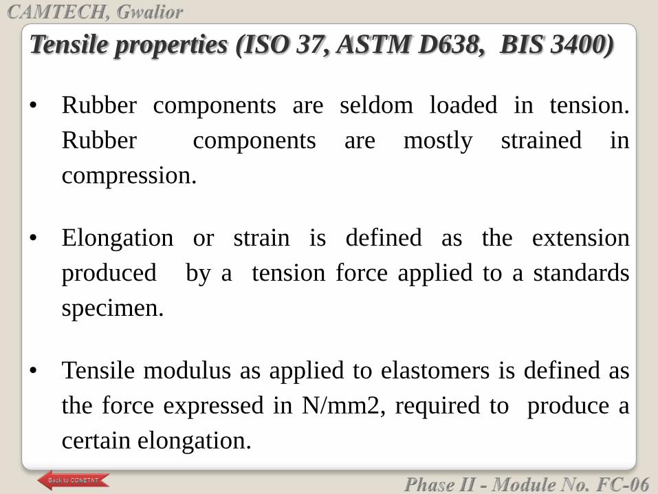
Tensile properties (ISO 37, ASTM D638, BIS 3400)
• Rubber components are seldom loaded in tension.
Rubber components are mostly strained in
compression.
• Elongation or strain is defined as the extension
produced by a tension force applied to a standards
specimen.
• Tensile modulus as applied to elastomers is defined as
the force expressed in N/mm2, required to produce a
certain elongation.
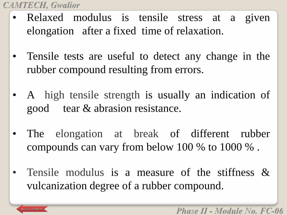
• Relaxed modulus is tensile stress at a given
elongation after a fixed time of relaxation.
• Tensile tests are useful to detect any change in the
rubber compound resulting from errors.
• A high tensile strength is usually an indication of
good tear & abrasion resistance.
• The elongation at break of different rubber
compounds can vary from below 100 % to 1000 % .
• Tensile modulus is a measure of the stiffness &
vulcanization degree of a rubber compound.
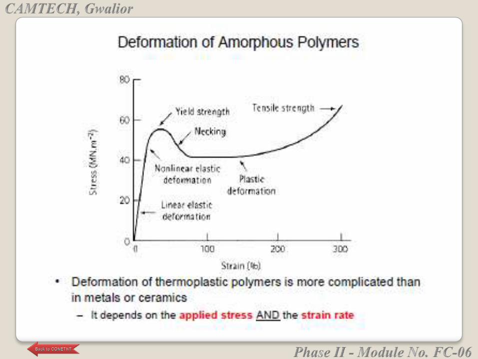
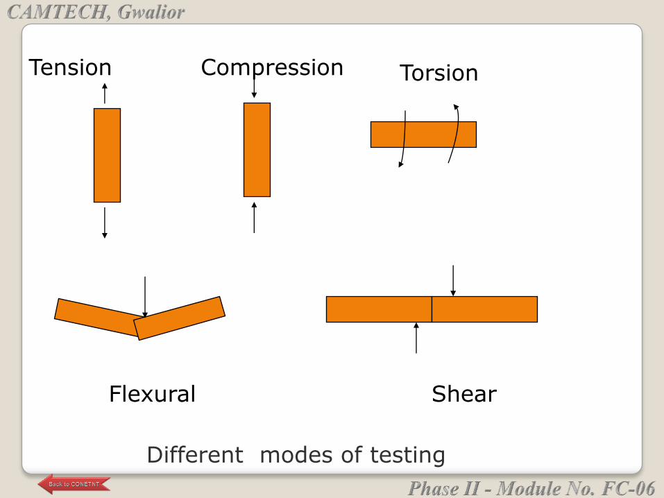
Tension Compression Torsion
Flexural Shear
Different modes of testing
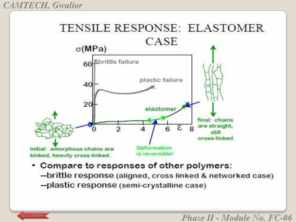
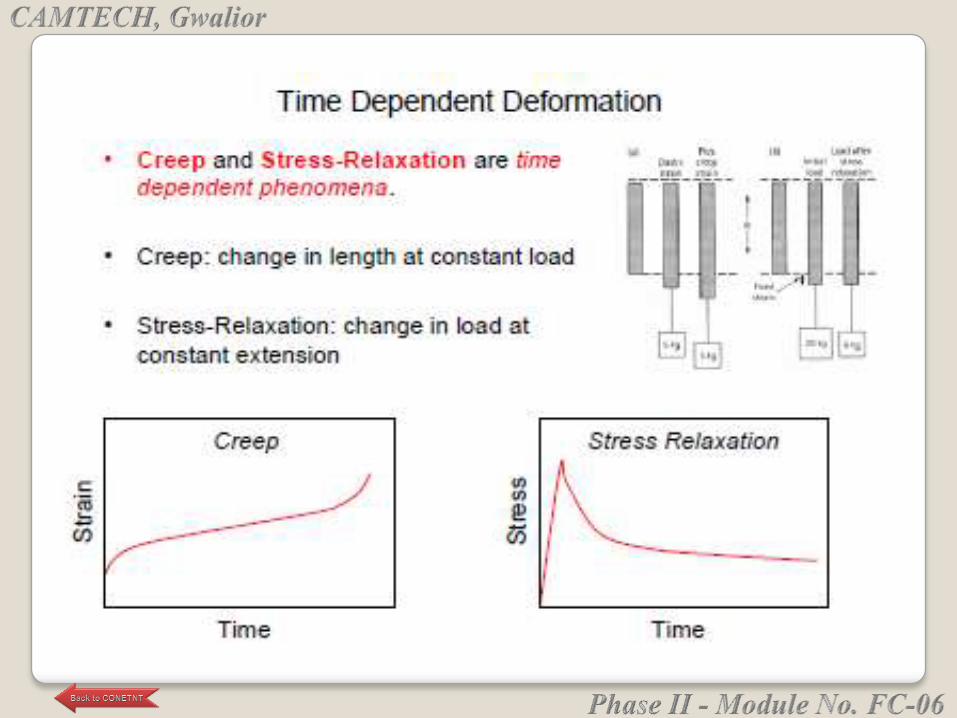
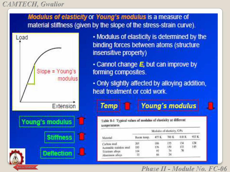
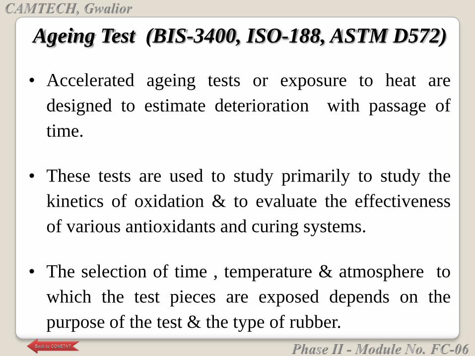
Ageing Test (BIS-3400, ISO-188, ASTM D572)
• Accelerated ageing tests or exposure to heat are
designed to estimate deterioration with passage of
time.
• These tests are used to study primarily to study the
kinetics of oxidation & to evaluate the effectiveness
of various antioxidants and curing systems.
• The selection of time , temperature & atmosphere to
which the test pieces are exposed depends on the
purpose of the test & the type of rubber.
Permanent Set
• Rubber deform under load & rarely returns completely to
their original dimensions , when the load is removed.
• Prolonged deformation leads to some degree of
permanent deformation.
• Set is defined as the amount of deformation remaining
after removing the deforming force.
• Permanent set measurement they indicate the degree of
vulcanization that has taken place.
• Unsuitable compounds can often be identified if the
permanent set falls in high range.
Tension Set ( IS 3400 )
• The elastomer is stretched under specified conditions
& allowed to retract the extension expressed as a
percentage of the original length is called tension set.
• This test is intended to measure the ability of rubber to
retain their visco-elastic properties.
Compression Set ( ASTM D 395 )
• If the elastomer is compressed under specified
conditions, the residual decrease in its thickness
after complete release of the compressive force is
known as compression set.
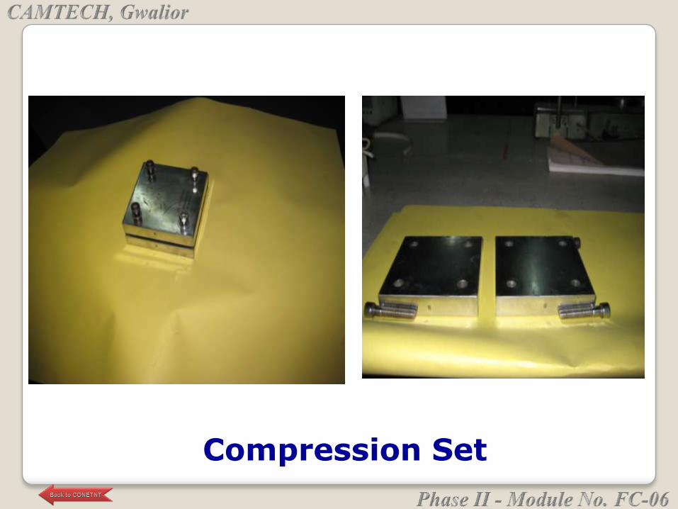
Compression Set
Load – deflection test in compression mode
• This test is generally done on finished products.
• In a compression testing machine , load is applied at a
given rate of loading . A graph is plotted between load
vs deflection.
• Load is recorded from load scale and deflection is
recorded from dial gauges or by digital readouts.
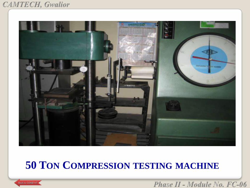
50 TON COMPRESSION TESTING MACHINE

Resistance to liquids ( ISO 1817, ASTM D 471 )
• The amount of swelling is used as a measure of
resistance of a rubber to a liquid , such as oil.
• The action of a liquid on a vulcanised rubber results in
absorption of liquids by rubber or extraction of a
soluble constituent from a rubber.
• Rubber gaskets for transformer in locomotives &
engine mounts are exposed to oil.
• The swelling test can provide valuable information on
the suitability of a rubber compound
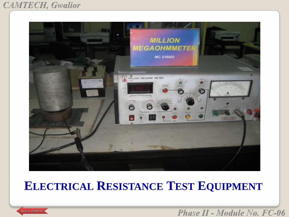
ELECTRICAL RESISTANCE TEST EQUIPMENT

• Tear resistance is defined as maximum force per unit
of thickness required to tear a specified test piece.
• Tear is more likely to occur where there is high
stress concentration at a nick or sharp angle.
• Low vulcanisation & short cure times give high tear
resistance.
Tear Resistance ( ASTM D 624 )
Stress Relaxation ( ISO 3384, DIN 53537 )
• It is defined as the loss in stress when it is held at a
constant strain (deformation ) over a period of time.
• This property in rubber may be defined as the
resistance to wearing away by rubbing or impact in
service.
• Dynamic seals can undergo abrasion when sliding
over a dry surface when friction is correspondingly
high.
Abrasion Test ( ASTM D 1630 )
Resilience ( ASTM D 1054)
• Resilience is essentially the ability of an elastomer to
return quickly to its original shape.
• The ratio of energy returned to energy applied to
produce the deformation is the material‘s resilience.
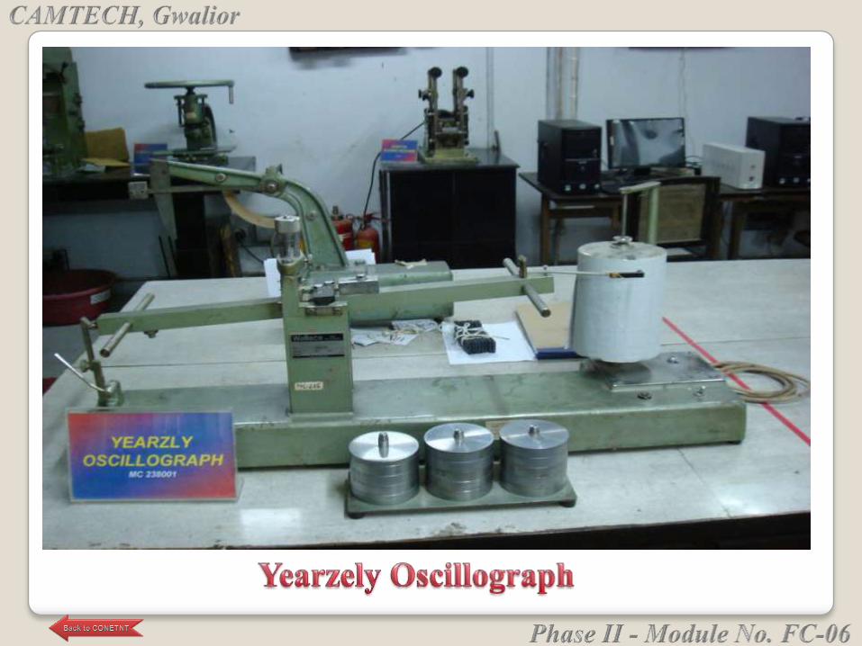
• It is the temperature rise in an elastomeric part due to
hysteresis. It occurs as a result of rapid cyclic load.
• When the elastomer is repeatedly deformed , heat is
generated throughout the bulk of the material as
elastomers are poor conductors of heat..
Electrical properties
• Elastomers are normally good insulators with
relatively high electrical resistivity.
• Belts, hoses, footwear require sufficient electrical
conductivity to prevent buildup of electrical charges.
Heat Built-up ( ASTM D 623)
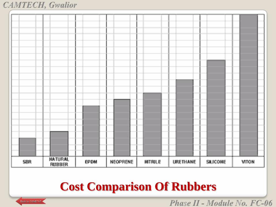
Cost Comparison Of Rubbers
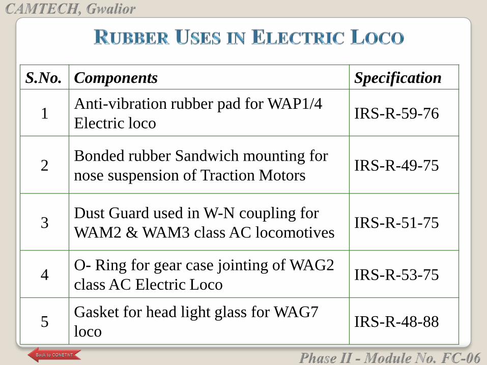
S.No. Components Specification
1Anti-vibration rubber pad for WAP1/4
Electric locoIRS-R-59-76
2Bonded rubber Sandwich mounting for
nose suspension of Traction MotorsIRS-R-49-75
3Dust Guard used in W-N coupling for
WAM2 & WAM3 class AC locomotivesIRS-R-51-75
4O- Ring for gear case jointing of WAG2
class AC Electric LocoIRS-R-53-75
5Gasket for head light glass for WAG7
loco IRS-R-48-88
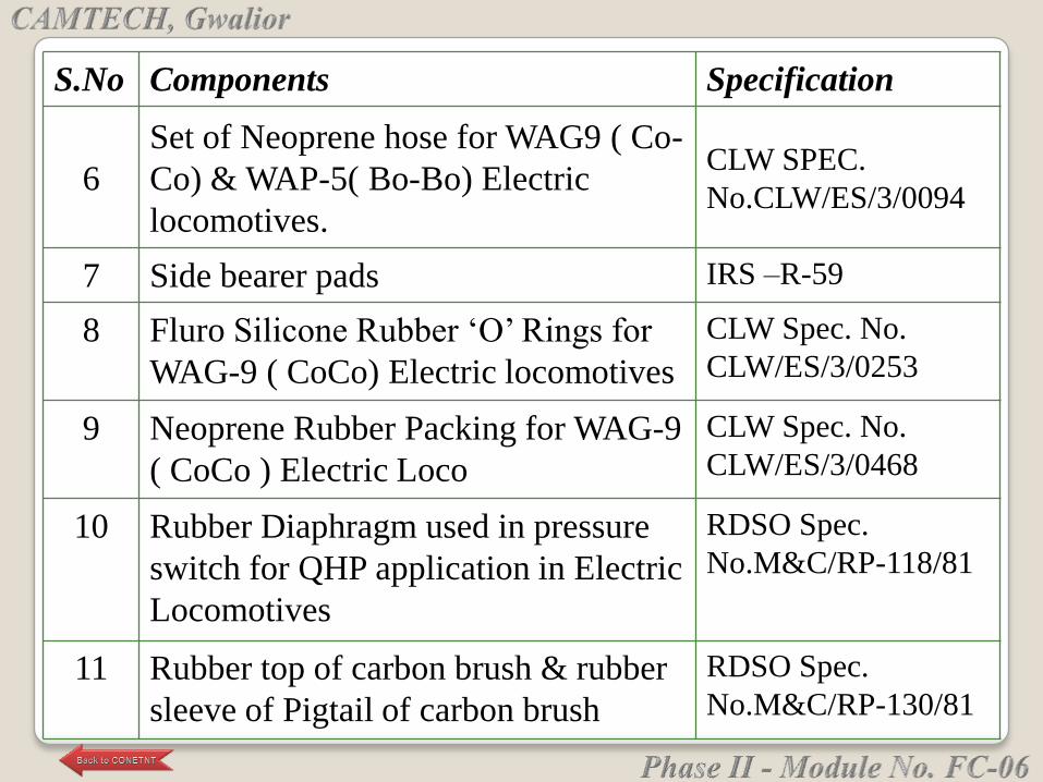
S.No Components Specification
6
Set of Neoprene hose for WAG9 ( Co-
Co) & WAP-5( Bo-Bo) Electric
locomotives.
CLW SPEC.
No.CLW/ES/3/0094
7 Side bearer pads IRS –R-59
8 Fluro Silicone Rubber ‗O‘ Rings for
WAG-9 ( CoCo) Electric locomotives
CLW Spec. No.
CLW/ES/3/0253
9 Neoprene Rubber Packing for WAG-9
( CoCo ) Electric Loco
CLW Spec. No.
CLW/ES/3/0468
10 Rubber Diaphragm used in pressure
switch for QHP application in Electric
Locomotives
RDSO Spec.
No.M&C/RP-118/81
11 Rubber top of carbon brush & rubber
sleeve of Pigtail of carbon brush
RDSO Spec.
No.M&C/RP-130/81
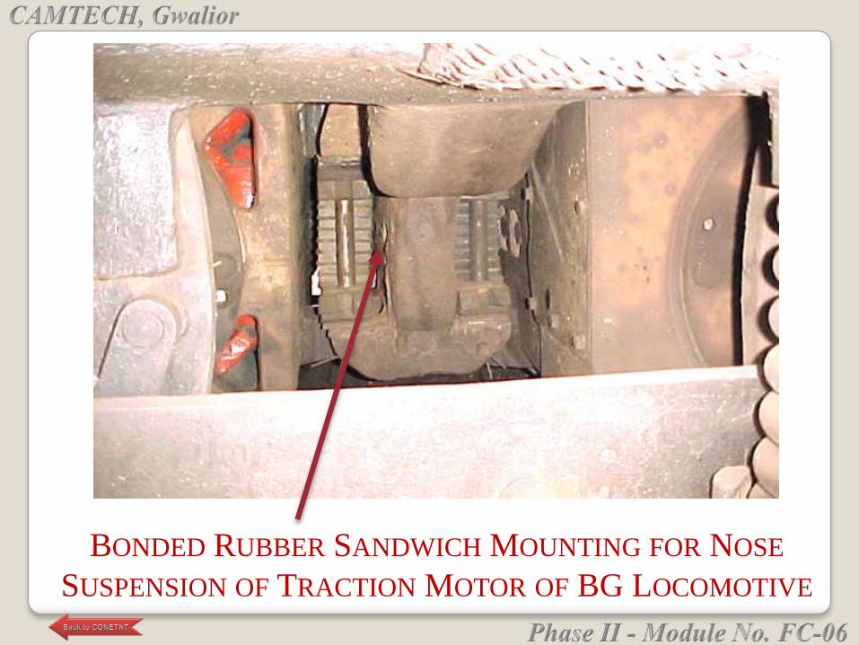
BONDED RUBBER SANDWICH MOUNTING FOR NOSE
SUSPENSION OF TRACTION MOTOR OF BG LOCOMOTIVE
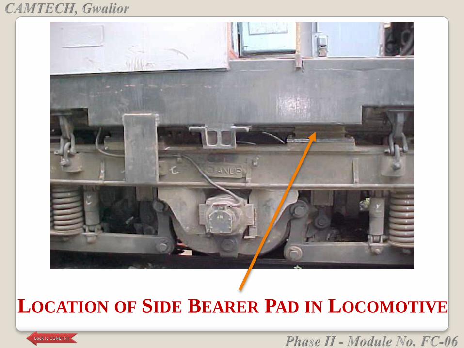
LOCATION OF SIDE BEARER PAD IN LOCOMOTIVE
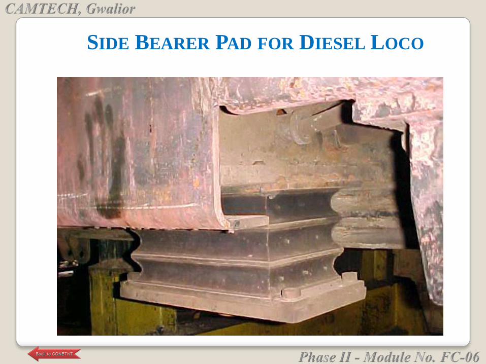
SIDE BEARER PAD FOR DIESEL LOCO
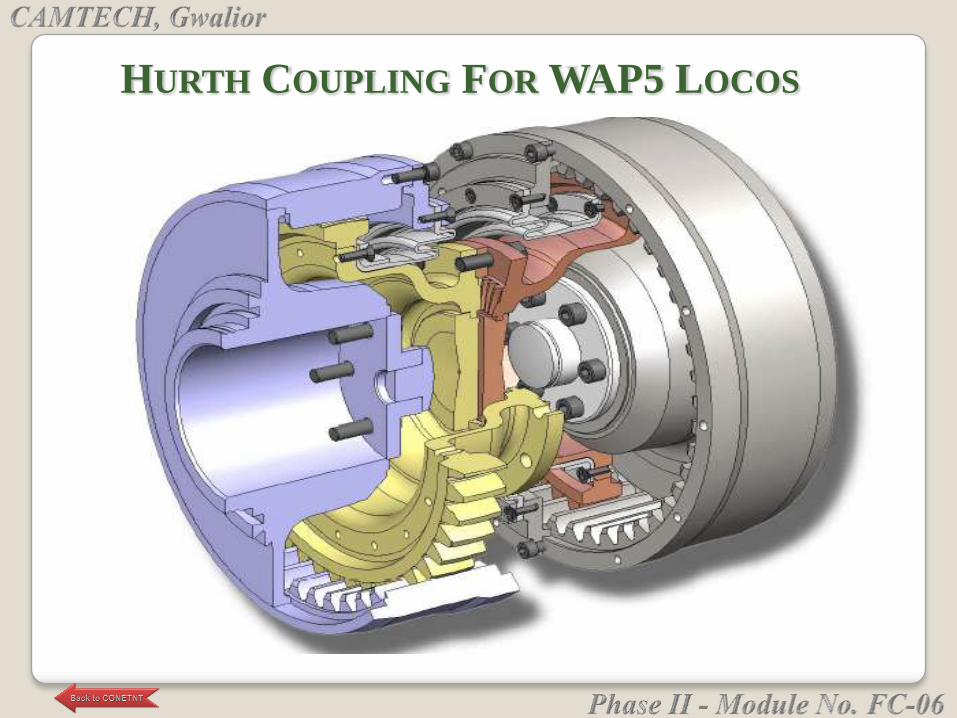
HURTH COUPLING FOR WAP5 LOCOS
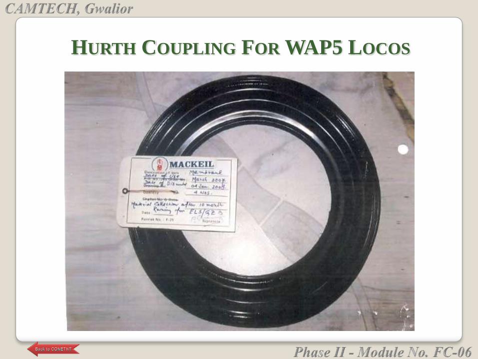
HURTH COUPLING FOR WAP5 LOCOS

TRACTION MOTOR BELLOW IN DIESEL LOCO
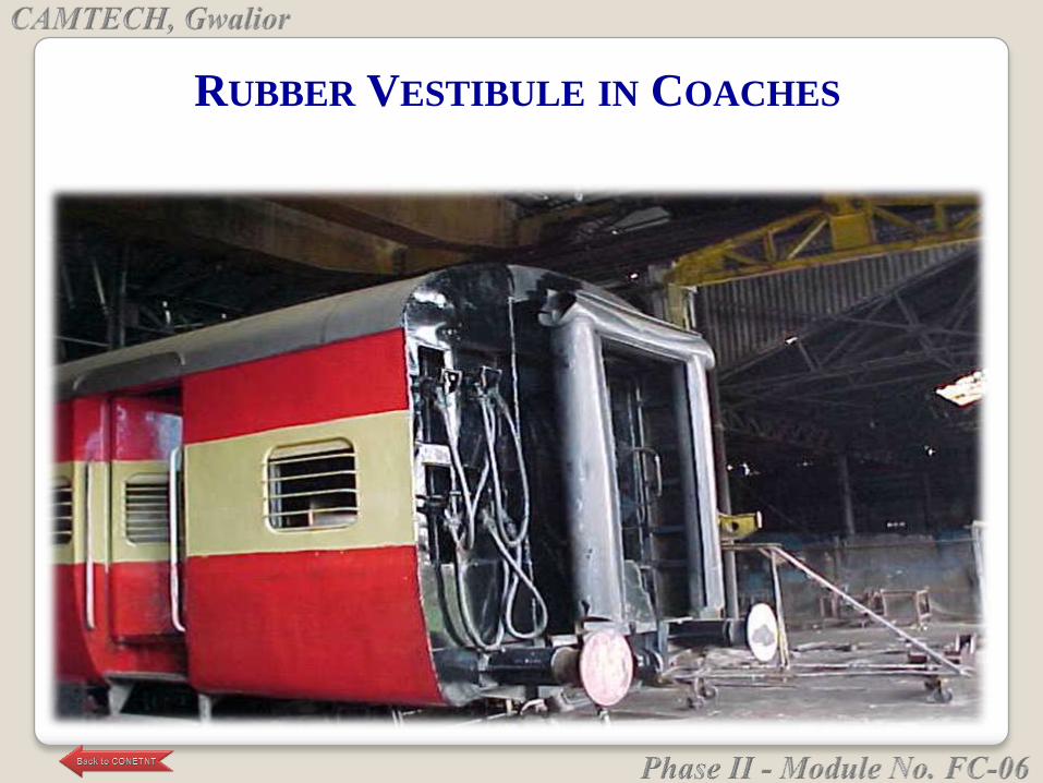
RUBBER VESTIBULE IN COACHES

Most rubbers change in physical properties during storage
and ultimately become unserviceable, due to excessive
hardening, softening, cracking, crazing, or other surface
degradation.
These changes may be the result of one particular factor
or a combination of factors, such as the action of oxygen,
ozone, light, heat, humidity or oils and solvents.
The deleterious effects of these factors may, however, be
minimized by careful choice of storage conditions.
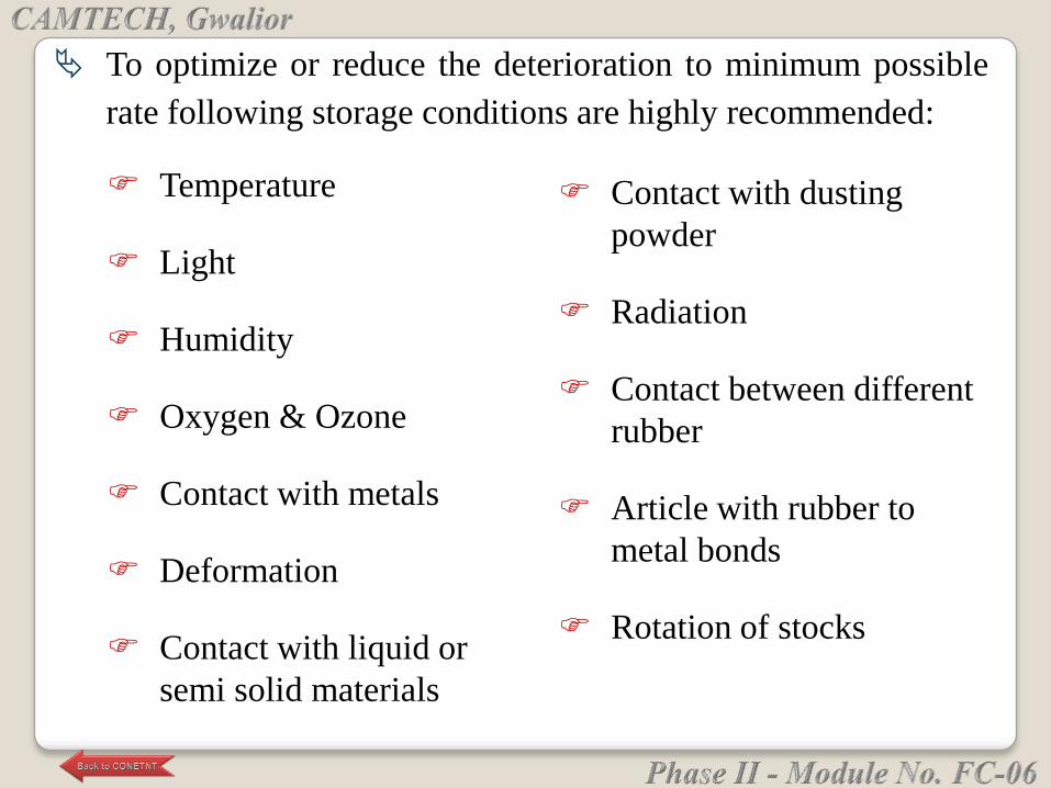
To optimize or reduce the deterioration to minimum possible
rate following storage conditions are highly recommended:
Temperature
Light
Humidity
Oxygen & Ozone
Contact with metals
Deformation
Contact with liquid or
semi solid materials
Contact with dusting
powder
Radiation
Contact between different
rubber
Article with rubber to
metal bonds
Rotation of stocks
The rubber components should be stored in a cool
place and packed condition as far as practicable,
preferably below 25°C (preferably between 15°C to
25°C) because at higher temperatures deterioration
occurs more rapidly.
Sources of heat in storage rooms if any should be so
arranged that the temperature of stored articles never
exceeds 25°C (Ref.: IS 6713 – 1996).
As per ESA/ FSA publication No. 009/98 also, it
should be below 25°C (77°F).
i. Temperature
As per RDSO letter no. SD.DEV.RBC dtd.
28.08.2007 it should be as far as practicable
preferably below 30°.
The effects of low temperature are not permanently
deleterious to rubber articles but they may become
stiffer if stored at low temperatures.
When articles are taken from low temperature storage
for immediate use, their temperature should be raised
to approximately 30°C throughout their mass before
they are put into service. (Leave it at room
temperature).
They should be kept away from direct sunlight preferably
in a dark place.
Direct sunlight causes much faster degradation of the rubber
components.
Rubbers should be protected from light, in particular direct
sunlight and strong artificial light with a high ultra-violet
content.
It is advisable to cover windows of storage rooms with a
red or orange coating or screen. (Ref.: IS 6713 – 1996)
It is also advisable to avoid windows in storage room if
possible.
ii. Light
The relative humidity of the storage condition
should not be more than 70% so that
condensation of moisture does not take place
on the surface of the components.
Very moist or very dry conditions should be
avoided. Where ventilation is necessary it
should be kept to a minimum.(Ref: Rubber
book issued by RDSO).
iii. Humidity
Where possible, rubber should be protected from
circulating air by wrapping, storage in airtight
containers or by other suitable means.
As ozone is particularly deleterious, storage
rooms should not contain any equipment that is
capable of generating ozone, such as mercury
vapour lamps, high voltage electrical equipment
giving rise to electric sparks or silent electrical
discharges.
iv. Oxygen & Ozone
In the vicinity of rubber components, any loose
electrical connections should be avoided, as the
arcing due to loose connections causes production
of ozone, which adversely affects rubber.
Ozone is particularly damaging, and causes a
"scission" of the carbon backbone polymer chain
into smaller chains.
Combustion gases and organic vapour shall be
excluded from storage rooms as they may give
rise to ozone via photochemical processes.
They should be stored away from contact with
certain metals and their alloys containing copper
and manganese or materials impregnated with
their compounds (except when bonded to them)
which act as poisoning agents resulting in their
faster degradation.
They shall be protected by wrapping or by
separation with a layer of suitable material for
example paper or polyethylene.
v. Contact with metals
Under no circumstances rubber components should be
stressed during storage. The portions under stress undergo
deformations with permanent set and leading to
degradation.
The material should be stacked in such a way so that any
super-imposed stresses are substantially avoided.
Rubbers should, wherever possible, be stored in a relaxed
condition free from tension, compression or other
deformation.
Large O-rings and seals shall not be suspended on pegs as
this will lead to severe deterioration.
vi. Deformation
Any contact with grease or oil should be avoided
as these cause swelling, softening and
deterioration of rubbers. Even people handling
rubber should ensure that their hands are
oil/grease free.
Rubbers should not be allowed to come into
contact with solvents, oil, greases or any other
semi-solid materials at any time during storage,
unless so packed by the manufacturer.
vii. Contact with liquid or semi solid materials
A small amount of French chalk or soapstone or
mica may be applied on the surface of rubber
components for the packaging in order to prevent
blocking.
In such instances the minimum quantity of
powder to prevent adhesion shall be used.
Note: Any powder used shall be free from
any constituent having a deleterious effect on the
rubber or the subsequent applications of rubber.
viii. Contact with dusting powder
ix. Radiation
Precautions shall be taken to protect stored
articles from all sources of ionizing radiation
likely to cause damage to stored articles.
x. Contact between different rubber
Contact between rubbers of different composition
and colour shall be avoided.
The metal parts of bonded metal items shall not
come into contact with the rubber of others
articles.
Any preservative used on the metal shall be such
that it will not affect the rubber or the bond to
such an extent that it does not comply with the
product specification.
xi. Article with rubber to metal bonds

Great care is to be exercised so that the material is
used in the order of their receipt in the stores i.e.
first-in-first-out basis (FIFO).
The rubbers whether under storage or in use continue
to deteriorate.
The only difference is that under service condition
deterioration is much faster.
Every moment of storing is at the cost of useful life
and prolonged storage of the material may render it
unserviceable due to progressive deterioration.
xii. Rotation of stocks
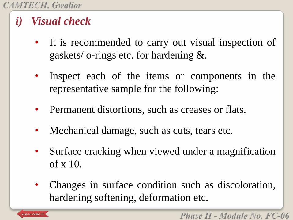
i) Visual check
• It is recommended to carry out visual inspection of
gaskets/ o-rings etc. for hardening &.
• Inspect each of the items or components in the
representative sample for the following:
• Permanent distortions, such as creases or flats.
• Mechanical damage, such as cuts, tears etc.
• Surface cracking when viewed under a magnification
of x 10.
• Changes in surface condition such as discoloration,
hardening softening, deformation etc.
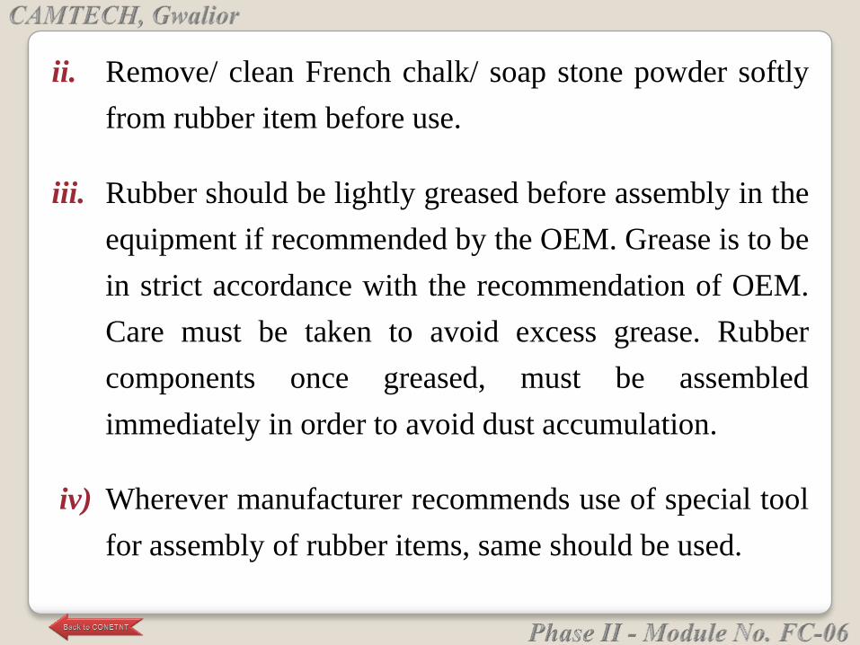
ii. Remove/ clean French chalk/ soap stone powder softly
from rubber item before use.
iii. Rubber should be lightly greased before assembly in the
equipment if recommended by the OEM. Grease is to be
in strict accordance with the recommendation of OEM.
Care must be taken to avoid excess grease. Rubber
components once greased, must be assembled
immediately in order to avoid dust accumulation.
iv) Wherever manufacturer recommends use of special tool
for assembly of rubber items, same should be used.
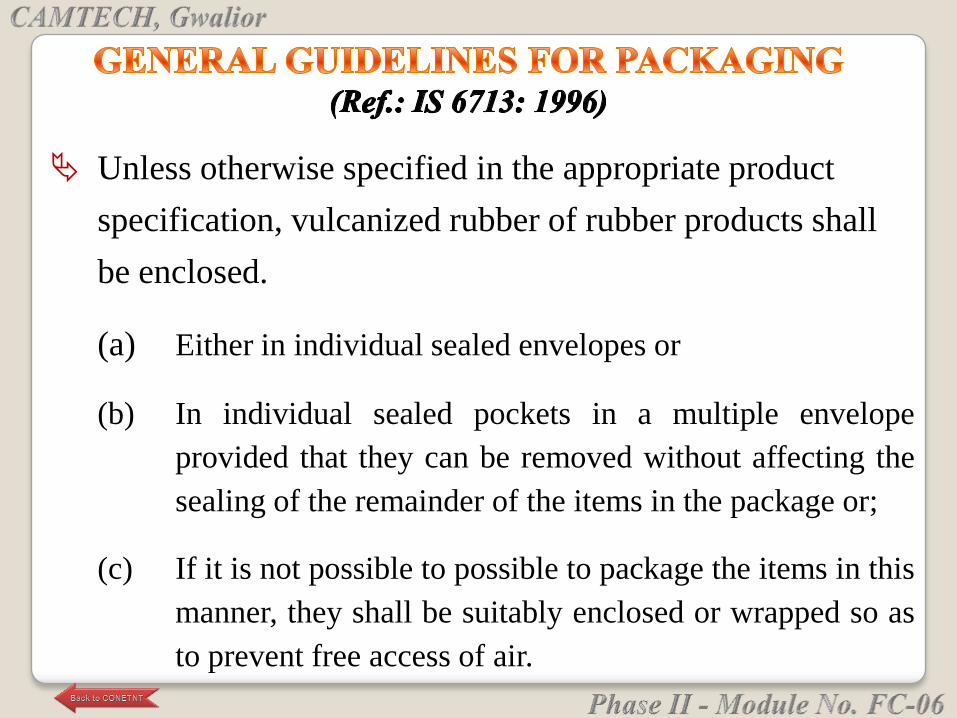
Unless otherwise specified in the appropriate product
specification, vulcanized rubber of rubber products shall
be enclosed.
(a) Either in individual sealed envelopes or
(b) In individual sealed pockets in a multiple envelope
provided that they can be removed without affecting the
sealing of the remainder of the items in the package or;
(c) If it is not possible to possible to package the items in this
manner, they shall be suitably enclosed or wrapped so as
to prevent free access of air.
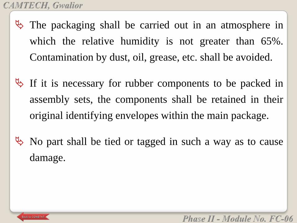
The packaging shall be carried out in an atmosphere in
which the relative humidity is not greater than 65%.
Contamination by dust, oil, grease, etc. shall be avoided.
If it is necessary for rubber components to be packed in
assembly sets, the components shall be retained in their
original identifying envelopes within the main package.
No part shall be tied or tagged in such a way as to cause
damage.


(Purification of copper by electrolysis)
is a chemical element with
symbol Cu (from Latin: cuprum) and atomic
number 29.
It is a soft, malleable and ductile metal with very
high thermal and electrical conductivity.
A freshly exposed surface of pure copper has a reddish-
orange color.
It is used as a conductor of heat and electricity, as a
building material and as a constituent of various
metal alloys, thermocouples for temperature
measurement etc.
Copper is found as a pure metal in nature, and this was
the first source of the metal to be used by humans, c. 8000
BC.
It was the first metal to be smelted from its ore, c. 5000
BC, the first metal to be cast into a shape in a mold, c.
4000 BC and the first metal to be purposefully alloyed
with another metal, tin, to create bronze, c. 3,500 BC.
In the Roman era, copper was principally mined
on Cyprus, the origin of the name of the metal, from aes
сyprium (metal of Cyprus), later corrupted to сuprum,
from which the words copper (English) are all derived.
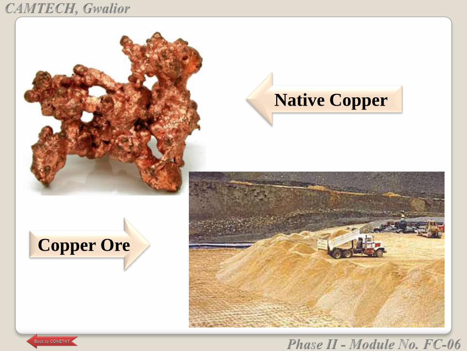
Native Copper
Copper Ore
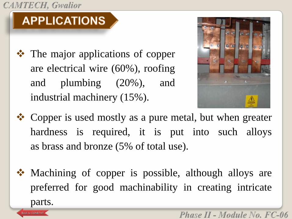
Copper is used mostly as a pure metal, but when greater
hardness is required, it is put into such alloys
as brass and bronze (5% of total use).
Machining of copper is possible, although alloys are
preferred for good machinability in creating intricate
parts.
The major applications of copper
are electrical wire (60%), roofing
and plumbing (20%), and
industrial machinery (15%).
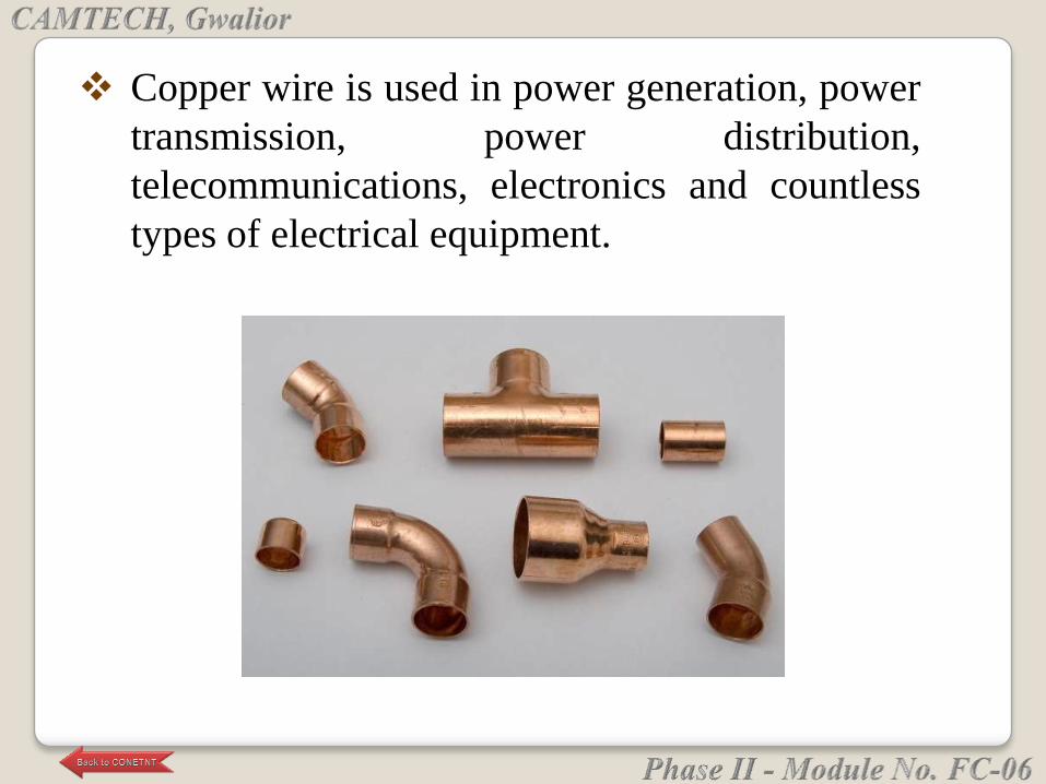
Copper wire is used in power generation, power
transmission, power distribution,
telecommunications, electronics and countless
types of electrical equipment.
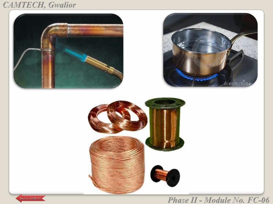
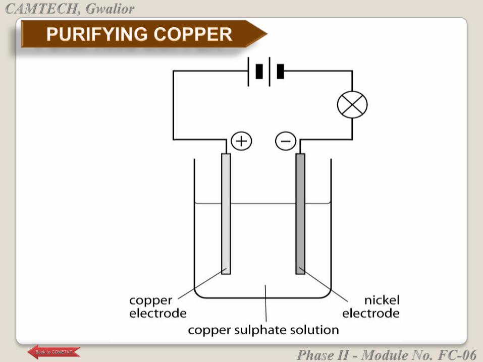
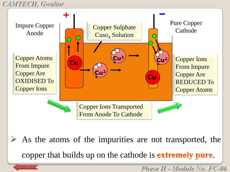
As the atoms of the impurities are not transported, the
copper that builds up on the cathode is .
Impure Copper
Anode
Pure Copper
CathodeCopper Sulphate
Cuso4 Solution
Cu2
+ Cu
CuCu2
+ Cu2
+
Copper Atoms
From Impure
Copper Are
OXIDISED To
Copper Ions
Copper Ions Transported
From Anode To Cathode
Copper Ions
From Impure
Copper Are
REDUCED To
Copper Atoms
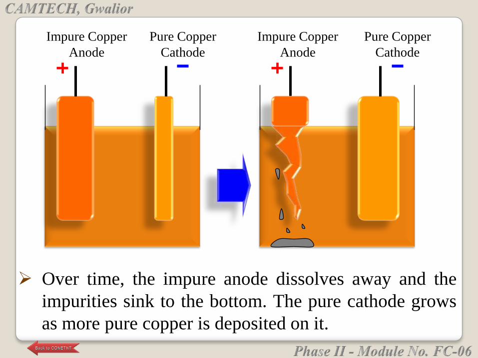
Impure Copper
Anode
Pure Copper
Cathode
Impure Copper
Anode
Pure Copper
Cathode
Over time, the impure anode dissolves away and the
impurities sink to the bottom. The pure cathode grows
as more pure copper is deposited on it.
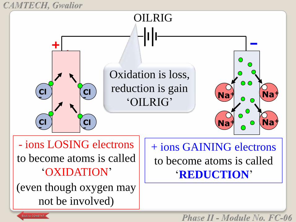
Cl-
Cl-
Cl-
Cl-
Na+ Na+
Na+ Na+
OILRIG
- ions LOSING electrons
to become atoms is called
‗OXIDATION‘
(even though oxygen may
not be involved)
+ ions GAINING electrons
to become atoms is called
‗REDUCTION‘
Oxidation is loss,
reduction is gain
‗OILRIG‘
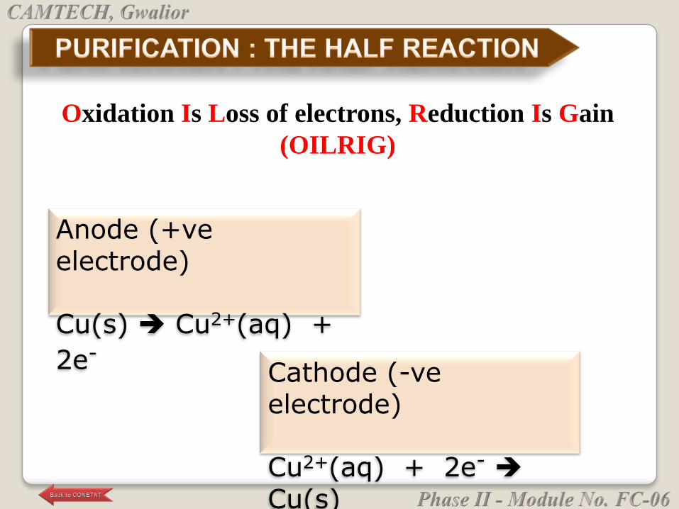
Anode (+ve electrode)
Cu(s) Cu2+(aq) +
2e-Cathode (-ve electrode)
Cu2+(aq) + 2e-
Cu(s)
Oxidation Is Loss of electrons, Reduction Is Gain
(OILRIG)
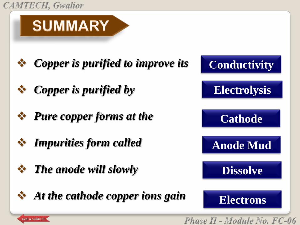
Copper is purified to improve its
Copper is purified by
Pure copper forms at the
Impurities form called
The anode will slowly
At the cathode copper ions gain
Conductivity
Electrolysis
Cathode
Anode Mud
Dissolve
Electrons