fermacell AESTUVER compact tunnels
48
Tunnels fermacell AESTUVER compact Last updated: April 2016
Transcript of fermacell AESTUVER compact tunnels
Tunnels
fermacell AESTUVERcompact
Last updated: April 2016
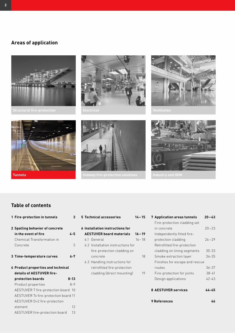
Areas of application
Structural fire-protection Electrical Ventilation
Tunnels Subway fire-protection solutions Industry and OEM
Table of contents
1 Fire-protection in tunnels 3
2 Spalling behavior of concrete in the event of fire 4-5 Chemical Transformation in Concrete 5
3 Time-temperature curves 6-7
4 Product properties and technical details of AESTUVER fire- protection boards 8-13 Product properties 8-9 AESTUVER T fire-protection board 10 AESTUVER Tx fire-protection board 11 AESTUVER D+2 fire-protection element 12 AESTUVER fire-protection board 13
5 Technical accessories 14 – 15
6 Installation instructions for AESTUVER board materials 16 – 19 6.1 General 16 – 18 6.2 Installation instructions for fire-protection cladding on concrete 18 6.3 Handling instructions for retrofitted fire-protection cladding (direct mounting) 19
7 Application areas tunnels 20 – 43 Fire-protection cladding set in concrete 20 – 23 Independently fitted fire- protection cladding 24 – 29 Retrofitted fire-protection cladding on lining segments 30-33 Smoke extraction layer 34-35 Finishes for escape and rescue routes 36-37 Fire-protection for joints 38-41 Design applications 42-43
8 AESTUVER services 44-45
9 References 46
2
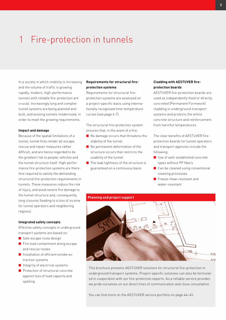
1 Fire-protection in tunnels
In a society in which mobility is increasing and the volume of traffic is growing rapidly, modern, high-performance tunnels with reliable fire-protection are crucial. Increasingly long and complex tunnel systems are being planned and built, and existing tunnels modernized, in order to meet the growing requirements.
Impact and damage Because of the spatial limitations of a tunnel, tunnel fires render all escape, rescue and repair measures rather difficult, and are hence regarded to be the greatest risk to people, vehicles and the tunnel structure itself. High-perfor-mance fire-protection systems are there-fore required to satisfy the demanding structural fire-protection requirements in tunnels. These measures reduce the risk of injury, and avoid severe fire damage to the tunnel structure and, consequently, long closures (leading to a loss of income for tunnel operators and neighboring regions).
Integrated safety conceptsEffective safety concepts in underground transport systems are based on:n Safe escape route designn Fire load containment along escape and rescue routes n Installation of efficient smoke ex- traction systemsn Integrity of electrical systemsn Protection of structural concrete against loss of load capacity and spalling
Requirements for structural fire- protection systemsRequirements for structural fire- protection systems are assessed on a project-specific basis using interna-tionally recognised time-temperature curves (see page 6-7). The structural fire-protection system ensures that, in the event of a fire:n No damage occurs that threatens the stability of the tunneln No permanent deformation of the structure occurs that restricts the usability of the tunneln The leak tightness of the structure is guaranteed on a continuous basis
This brochure presents AESTUVER solutions for structural fire-protection in underground transport systems. Project-specific solutions can also be formulat-ed in cooperation with our fire-protection experts. As a reliable service provider, we pride ourselves on our direct lines of communication and close consultation.
You can find more on the AESTUVER service portfolio on page 44–45.
Planning and project support
Cladding with AESTUVER fire- protection boardsAESTUVER fire-protection boards are used as independently fixed or directly concreted (Permanent Formwork) cladding in underground transport systems and protects the entire concrete structure and reinforcement from harmful temperatures.
The clear benefits of AESTUVER fire- protection boards for tunnel operators and transport agencies include the following:n Use of well-established concrete types without PP fibersn Can be cleaned using conventional cleaning processesn Freeze-thaw-resistant and water-resistant
3
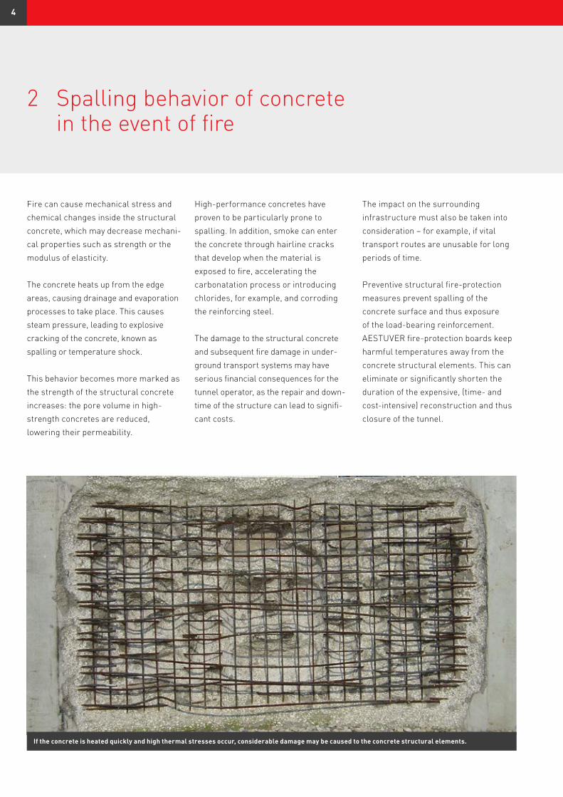
Fire can cause mechanical stress and chemical changes inside the structural concrete, which may decrease mechani-cal properties such as strength or the modulus of elasticity.
The concrete heats up from the edge areas, causing drainage and evaporation processes to take place. This causes steam pressure, leading to explosive cracking of the concrete, known as spalling or temperature shock.
This behavior becomes more marked as the strength of the structural concrete increases: the pore volume in high- strength concretes are reduced, lowering their permeability.
High-performance concretes have proven to be particularly prone to spalling. In addition, smoke can enter the concrete through hairline cracks that develop when the material is exposed to fire, accelerating the carbonatation process or introducing chlorides, for example, and corroding the reinforcing steel.
The damage to the structural concrete and subsequent fire damage in under-ground transport systems may have serious financial consequences for the tunnel operator, as the repair and down-time of the structure can lead to signifi-cant costs.
If the concrete is heated quickly and high thermal stresses occur, considerable damage may be caused to the concrete structural elements.
The impact on the surrounding infrastructure must also be taken into consideration – for example, if vital transport routes are unusable for long periods of time.
Preventive structural fire-protection measures prevent spalling of the concrete surface and thus exposure of the load-bearing reinforcement. AESTUVER fire-protection boards keep harmful temperatures away from the concrete structural elements. This can eliminate or significantly shorten the duration of the expensive, (time- and cost-intensive) reconstruction and thus closure of the tunnel.
2 Spalling behavior of concrete in the event of fire
4
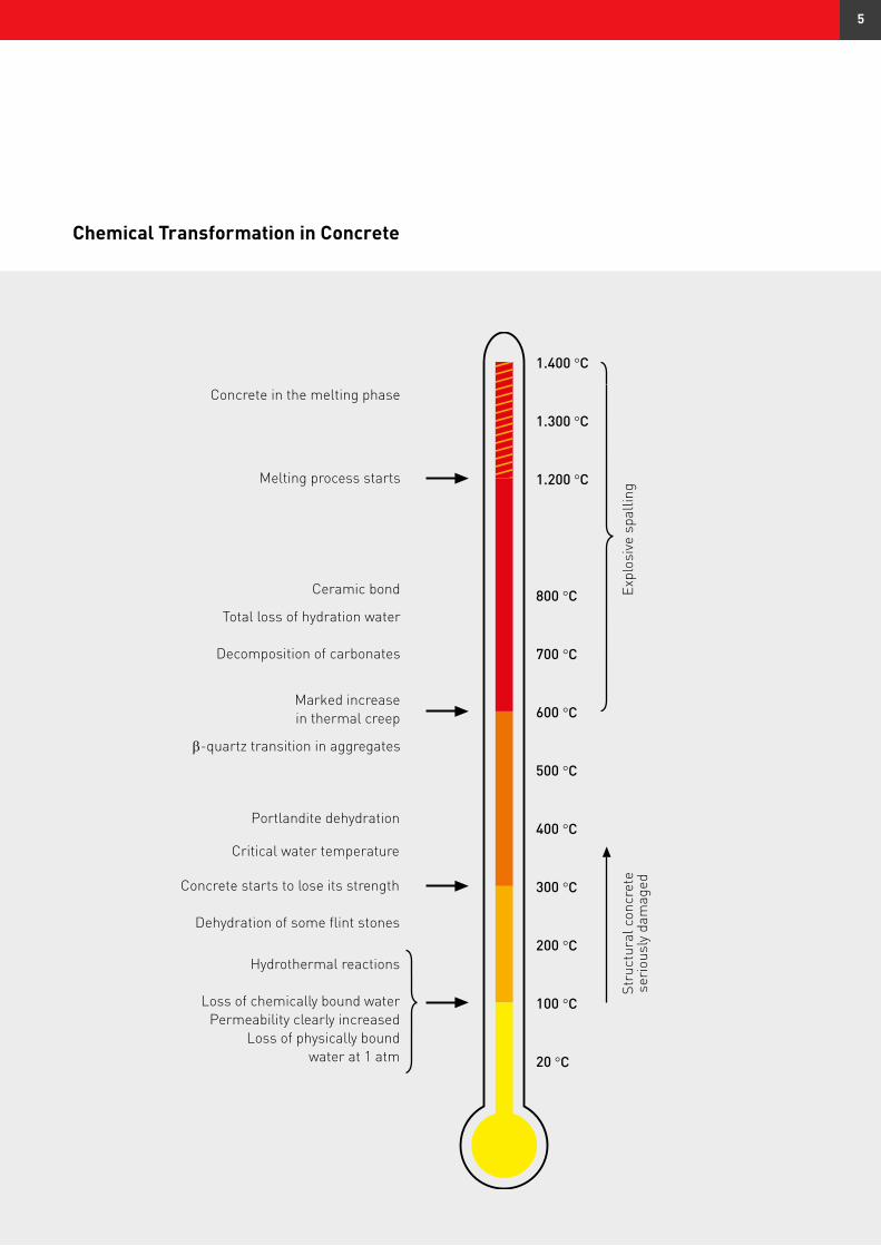
Hydrothermal reactions
Loss of chemically bound waterPermeability clearly increased
Loss of physically boundwater at 1 atm
Concrete starts to lose its strength
Dehydration of some flint stones
Portlandite dehydration
Critical water temperature
Concrete in the melting phase
Melting process starts
Ceramic bond
Total loss of hydration water
Decomposition of carbonates
Marked increasein thermal creep
β-quartz transition in aggregates
Expl
osiv
e sp
allin
gSt
ruct
ural
con
cret
ese
riou
sly
dam
aged
1.400 °C
1.300
1.200
800
700
600
500
400
300
200
100
20
°C
°C
°C
°C
°C
°C
°C
°C
°C
°C
°C
Chemical Transformation in Concrete
5
Tem
pera
ture
of fi
re c
ompa
rtm
ent [
°C]
Time [min]
The observance of these requirements and the relevant structural fire-protec-tion measures, such as cladding with AESTUVER fire-protection boards, is documented in advance with extensive fire tests.
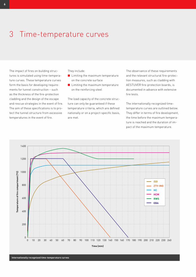
The internationally recognized time- temperature curves are outlined below. They differ in terms of fire development, the time before the maximum tempera-ture is reached and the duration of im-pact of the maximum temperature.
The impact of fires on building struc-tures is simulated using time-tempera-ture curves. These temperature curves form the basis for developing require-ments for tunnel construction – such as the thickness of the fire-protection cladding and the design of the escape and rescue strategies in the event of fire. The aim of these specifications is to pro-tect the tunnel structure from excessive temperatures in the event of fire.
They include:n Limiting the maximum temperature on the concrete surfacen Limiting the maximum temperature on the reinforcing steel
The load capacity of the concrete struc-ture can only be guaranteed if these temperature criteria, which are defined nationally or on a project-specific basis, are met.
0 10 20 30 40 50 60 70 80 90 100 110 120 130 140 150 160 170 180 190 200 210 220 230 2400
200
400
600
800
1000
1200
1400
ISO
ZTV-ING
HC
HCM
RWS
EBA
Internationally recognised time-temperature curves
3 Time-temperature curves
6
ISO curveThe ISO curve (ISO 834), also called the standard fire temperature curve, is the thermal stress generally applied in com-ponent analyses/tests in the building in-dustry. This thermal stress represents the lowest level of stress and reflects temperature requirements resulting from interior fires in buildings. The tim-ing of the ignition, smoldering and cool-ing phases is not taken into account.
ZTV-ING curve*/RABT curveIn accordance with ZTV-ING, the ZTV-ING curve applies to road tunnels in Germany regardless of their design and the type of traffic. It is vital to ensure that, under the temperature conditions of the ZTV-ING curve, the supporting reinforcement of the tunnel structure is not heated to a temperature exceeding 300°C and that only building materials of class A in accordance with DIN 4102 or equivalent are used. In addition, these building and general materials may not release any substances in the event of fire that are harmful to build-ings or people. EBA curve (EUREKA)Railroad tunnels must be designed to be self-supporting according to the state of the art and their intended use. The guideline from the EBA stipulates a fire curve defined by the German Federal Railroad Authority (Eisenbahn-Bundes-
amt, EBA). This fire curve is based on a temperature profile that has to allow for temperatures in the tunnel reaching 1 200°C after just 5 minutes. The EBA fire curve simulates the time-based temperature profile of fire gases that can occur in railroad tunnel systems in the event of damage. The EBA fire curve was confirmed with fire tests on long-distance passenger train cars as part of an EU project (EUREKA EN 499).
Hydrocarbon curve (HC)The hydrocarbon curve is an open fire curve from the 1970s and was devel-oped for hydrocarbon fires in industrial and offshore plants. This curve has been modified to take into account the higher fire loads in tunnels. According to the curve, the fire development is similar to a gasoline or diesel pool fire, but can also be used qualitatively for a solids fire.
Modified hydrocarbon curve (HCM)The modified hydrocarbon curve (HCM) was developed in France to take into ac-count the increased safety require-ments in tunnel structures, and is based on the hydrocarbon curve (HC). The HCM curve, derived from the hydro-carbon curve described previously, reaches a maximum temperature of 1 300°C (HC curve = maximum of 1 100°C).
The HCM curve is being used increas-ingly in large international infrastruc-ture projects.
Rijkswaterstaat curve (RWS)The Rijkswaterstaat curve is an open fire curve based on a tanker fire with 45 000 liters of gasoline. In the modified variant, the temperature of 1 200°C, which is reached after the fire has been burning for 2 hours, is maintained for an additional hour.
N0, N1, N2, N3 According to the CETU** guidelineIn France, there are more far-reaching requirements for fire-protection in road tunnels, depending on the size and in-frastructural importance, in accordance with the CETU** guideline. There are four categories: N0, N1, N2 and N3. The categories represent a combination of the different time-temperature curves and have the following meanings:n N0 = no requirement n N1 = HCM 60 minutes and ISO 120 minutes n N2 = HCM 120 minutesn N3 = HCM 120 minutes and ISO 240 minutes
* ZTV-ING: Zusätzliche Technische Vertragsbedingungen und Richtlinien für Ingenieurbauten (Additional Technical Terms of Contract and Guidelines for Civil Engineering Structures)** Centre d’études des tunnels
AESTUVER board
materials meet or exceed
the high specifications
of international time-
temperature curves.
7
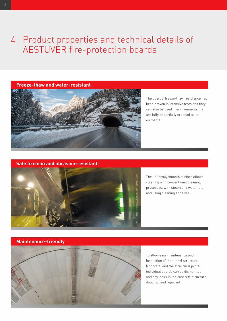
Freeze-thaw and water-resistant
Safe to clean and abrasion-resistant
Phot
o: F
ranz
Pfis
ter
AG, S
chw
eiz
(© T
hom
as G
uhl)
The uniformly smooth surface allows cleaning with conventional cleaning processes, with steam and water jets, and using cleaning additives.
The boards’ freeze-thaw resistance has been proven in intensive tests and they can also be used in environments that are fully or partially exposed to the elements.
Maintenance-friendly
To allow easy maintenance and inspection of the tunnel structure (concrete) and the structural joints, individual boards can be dismantled and any leaks in the concrete structure detected and repaired.
4 Product properties and technical details of AESTUVER fire-protection boards
Phot
o: ©
Mar
co F
ardi
n –
Foto
lia.c
om
8
Phot
o: T
äby
Bra
ndsk
ydds
Tekn
ik A
B
Phot
o: T
äby
Bra
ndsk
ydds
Tekn
ik A
B
Verarbeitungs- und montagefreundlich
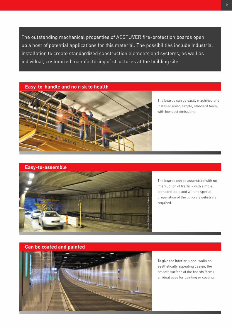
The boards can be easily machined and installed using simple, standard tools, with low dust emissions.
Easy-to-handle and no risk to health
Can be coated and painted
To give the interior tunnel walls an aesthetically appealing design, the smooth surface of the boards forms an ideal base for painting or coating.
Easy-to-assemble
The boards can be assembled with no interruption of traffic – with simple, standard tools and with no special preparation of the concrete substrate required.
The outstanding mechanical properties of AESTUVER fire-protection boards open
up a host of potential applications for this material. The possibilities include industrial
installation to create standardized construction elements and systems, as well as
individual, customized manufacturing of structures at the building site.
9
Technical data – AESTUVER T fire-protection boards
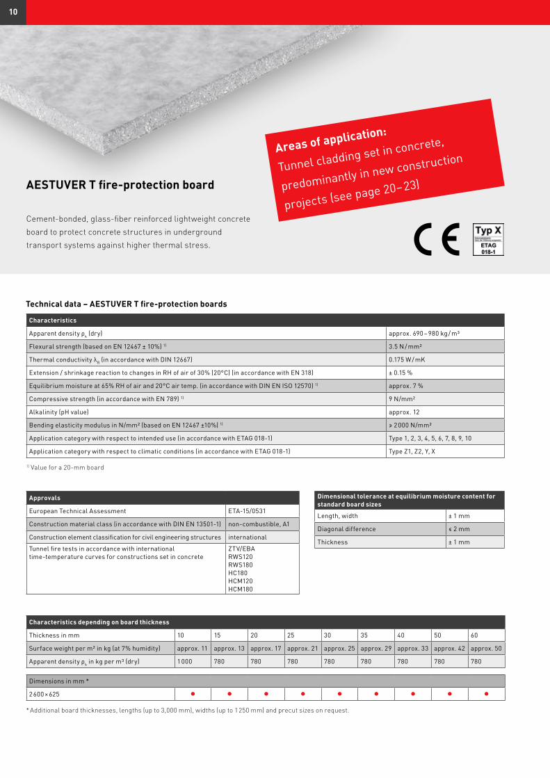
AESTUVER T fire-protection board
Cement-bonded, glass-fiber reinforced lightweight concrete board to protect concrete structures in underground transport systems against higher thermal stress.
Characteristics
Apparent density ρk (dry) approx. 690 – 980 kg / m³
Flexural strength (based on EN 12467 ± 10%) 1) 3.5 N / mm²
Thermal conductivity λR (in accordance with DIN 12667) 0.175 W / mK
Extension / shrinkage reaction to changes in RH of air of 30% (20°C) (in accordance with EN 318) ± 0.15 %
Equilibrium moisture at 65% RH of air and 20°C air temp. (in accordance with DIN EN ISO 12570) 1) approx. 7 %
Compressive strength (in accordance with EN 789) 1) 9 N/mm²
Alkalinity (pH value) approx. 12
Bending elasticity modulus in N/mm² (based on EN 12467 ±10%) 1) ≥ 2 000 N/mm²
Application category with respect to intended use (in accordance with ETAG 018-1) Type 1, 2, 3, 4, 5, 6, 7, 8, 9, 10
Application category with respect to climatic conditions (in accordance with ETAG 018-1) Type Z1, Z2, Y, X
1) Value for a 20-mm board
Approvals
European Technical Assessment ETA-15/0531
Construction material class (in accordance with DIN EN 13501-1) non-combustible, A1
Construction element classification for civil engineering structures international
Tunnel fire tests in accordance with international time-temperature curves for constructions set in concrete
ZTV/EBARWS120 RWS180 HC180HCM120HCM180
Characteristics depending on board thickness
Thickness in mm 10 15 20 25 30 35 40 50 60
Surface weight per m² in kg (at 7% humidity) approx. 11 approx. 13 approx. 17 approx. 21 approx. 25 approx. 29 approx. 33 approx. 42 approx. 50
Apparent density ρk in kg per m³ (dry) 1 000 780 780 780 780 780 780 780 780
Dimensions in mm *
2 600 × 625 l l l l l l l l l
* Additional board thicknesses, lengths (up to 3,000 mm), widths (up to 1 250 mm) and precut sizes on request.
Dimensional tolerance at equilibrium moisture content for standard board sizes
Length, width ± 1 mm
Diagonal difference ≤ 2 mm
Thickness ± 1 mm
Areas of application:
Tunnel cladding set in concrete,
predominantly in new construction
projects (see page 20– 23)
10
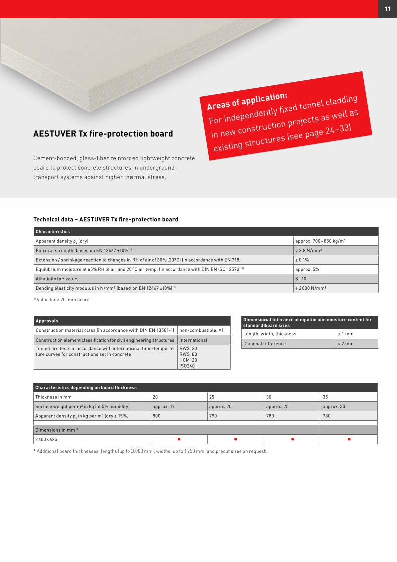
AESTUVER Tx fire-protection board
Cement-bonded, glass-fiber reinforced lightweight concrete board to protect concrete structures in underground transport systems against higher thermal stress.
Technical data – AESTUVER Tx fire-protection board
Characteristics
Apparent density ρk (dry) approx. 700 – 850 kg/m³
Flexural strength (based on EN 12467 ±10%) 1) ≥ 2.8 N/mm²
Extension / shrinkage reaction to changes in RH of air of 30% (20°C) (in accordance with EN 318) ± 0.1%
Equilibrium moisture at 65% RH of air and 20°C air temp. (in accordance with DIN EN ISO 12570) 1) approx. 5%
Alkalinity (pH value) 8 – 10
Bending elasticity modulus in N/mm² (based on EN 12467 ±10%) 1) ≥ 2 000 N/mm²
1) Value for a 20-mm board
Approvals
Construction material class (in accordance with DIN EN 13501-1) non-combustible, A1
Construction element classification for civil engineering structures International
Tunnel fire tests in accordance with international time-tempera-ture curves for constructions set in concrete
RWS120RWS180 HCM120ISO240
Dimensional tolerance at equilibrium moisture content for standard board sizes
Length, width, thickness ± 1 mm
Diagonal difference ≤ 2 mm
Characteristics depending on board thickness
Thickness in mm 20 25 30 35
Surface weight per m² in kg (at 5% humidity) approx. 17 approx. 20 approx. 25 approx. 30
Apparent density ρk in kg per m³ (dry ± 15 %) 800 790 780 780
Dimensions in mm *
2 600 × 625 l l l l
* Additional board thicknesses, lengths (up to 3,000 mm), widths (up to 1 250 mm) and precut sizes on request.
Areas of application:
For independently fixed tunnel cladding
in new construction projects as well as
existing structures (see page 24– 33)
11
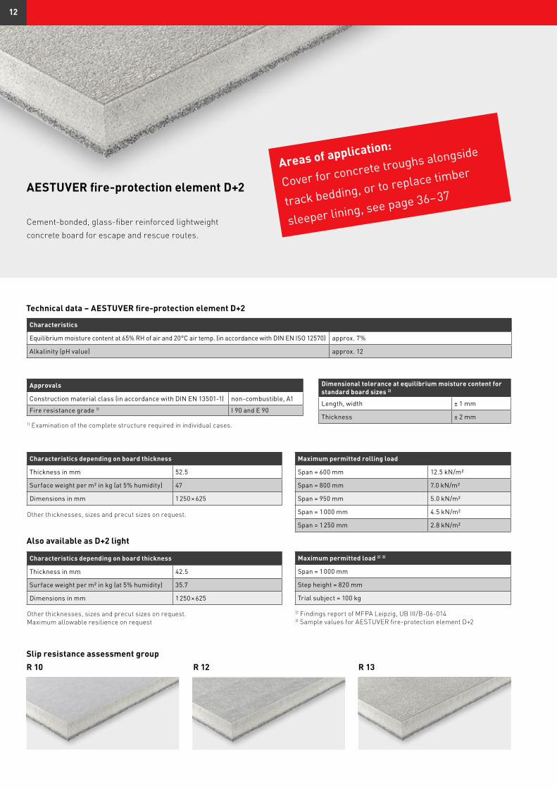
Technical data – AESTUVER fire-protection element D+2
Characteristics
Equilibrium moisture content at 65% RH of air and 20°C air temp. (in accordance with DIN EN ISO 12570) approx. 7%
Alkalinity (pH value) approx. 12
Approvals
Construction material class (in accordance with DIN EN 13501-1) non-combustible, A1
Fire resistance grade 1) I 90 and E 90
1) Examination of the complete structure required in individual cases.
Dimensional tolerance at equilibrium moisture content for standard board sizes 3)
Length, width ± 1 mm
Thickness ± 2 mm
Characteristics depending on board thickness
Thickness in mm 52.5
Surface weight per m² in kg (at 5% humidity) 47
Dimensions in mm 1 250 × 625
Other thicknesses, sizes and precut sizes on request.
Maximum permitted rolling load
Span = 600 mm 12.5 kN/m²
Span = 800 mm 7.0 kN/m²
Span = 950 mm 5.0 kN/m²
Span = 1 000 mm 4.5 kN/m²
Span = 1 250 mm 2.8 kN/m²
Slip resistance assessment groupR 10 R 12 R 13
Characteristics depending on board thickness
Thickness in mm 42.5
Surface weight per m² in kg (at 5% humidity) 35.7
Dimensions in mm 1 250 × 625
Other thicknesses, sizes and precut sizes on request. Maximum allowable resilience on request
Also available as D+2 light
AESTUVER fire-protection element D+2
Cement-bonded, glass-fiber reinforced lightweight concrete board for escape and rescue routes.
Areas of application:
Cover for concrete troughs alongside
track bedding, or to replace timber
sleeper lining, see page 36– 37
Maximum permitted load 2) 3)
Span = 1 000 mm
Step height = 820 mm
Trial subject = 100 kg
2) Findings report of MFPA Leipzig, UB III/B-06-0143) Sample values for AESTUVER fire-protection element D+2
12
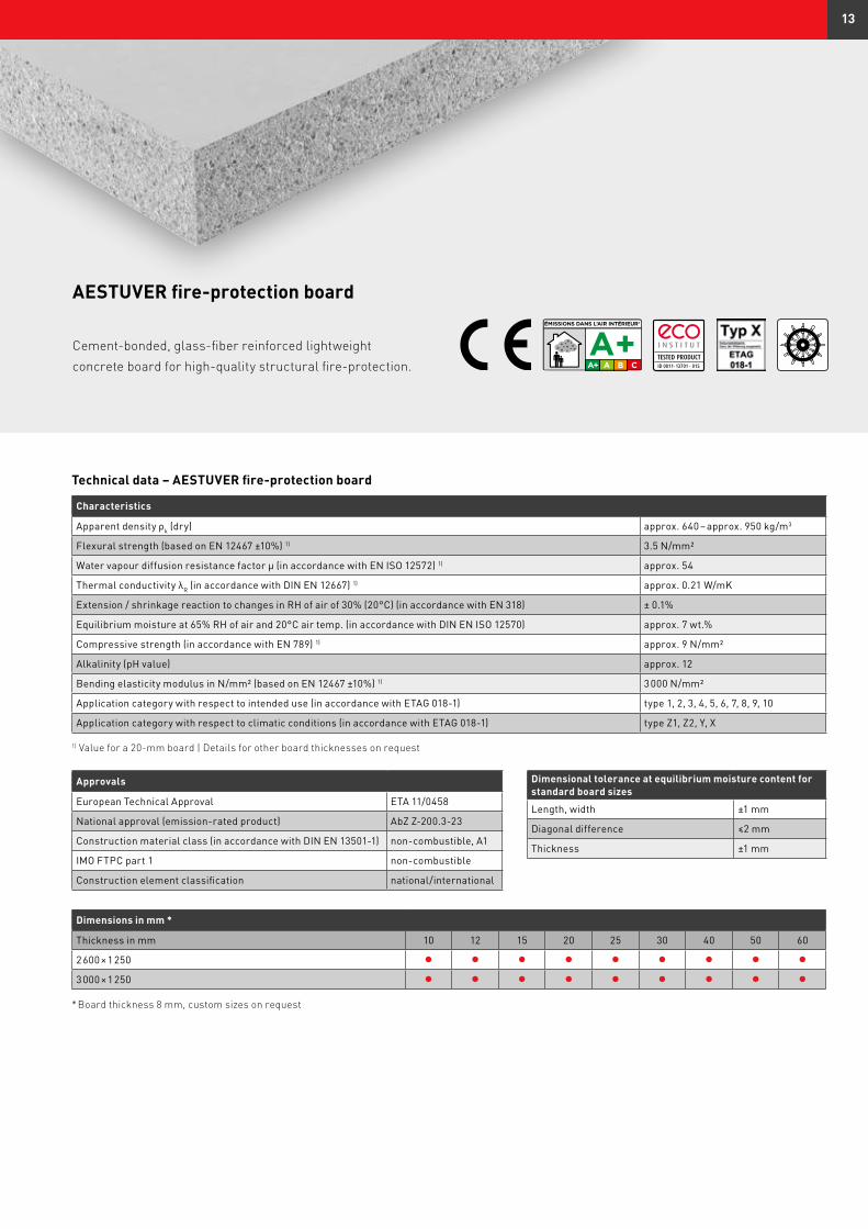
AESTUVER fire-protection board
Cement-bonded, glass-fiber reinforced lightweight concrete board for high-quality structural fire-protection.
Characteristics
Apparent density ρk (dry) approx. 640 – approx. 950 kg/m3
Flexural strength (based on EN 12467 ±10%) 1) 3.5 N/mm²
Water vapour diffusion resistance factor μ (in accordance with EN ISO 12572) 1) approx. 54
Thermal conductivity λR (in accordance with DIN EN 12667) 1) approx. 0.21 W/mK
Extension / shrinkage reaction to changes in RH of air of 30% (20°C) (in accordance with EN 318) ± 0.1%
Equilibrium moisture at 65% RH of air and 20°C air temp. (in accordance with DIN EN ISO 12570) approx. 7 wt.%
Compressive strength (in accordance with EN 789) 1) approx. 9 N/mm²
Alkalinity (pH value) approx. 12
Bending elasticity modulus in N/mm² (based on EN 12467 ±10%) 1) 3 000 N/mm²
Application category with respect to intended use (in accordance with ETAG 018-1) type 1, 2, 3, 4, 5, 6, 7, 8, 9, 10
Application category with respect to climatic conditions (in accordance with ETAG 018-1) type Z1, Z2, Y, X
1) Value for a 20-mm board | Details for other board thicknesses on request
Approvals
European Technical Approval ETA 11/0458
National approval (emission-rated product) AbZ Z-200.3-23
Construction material class (in accordance with DIN EN 13501-1) non-combustible, A1
IMO FTPC part 1 non-combustible
Construction element classification national/international
Dimensions in mm *
Thickness in mm 10 12 15 20 25 30 40 50 60
2 600 × 1 250 l l l l l l l l l
3 000 × 1 250 l l l l l l l l l
* Board thickness 8 mm, custom sizes on request
Dimensional tolerance at equilibrium moisture content for standard board sizes
Length, width ±1 mm
Diagonal difference ≤2 mm
Thickness ±1 mm
Technical data – AESTUVER fire-protection board
ID 0811- 13701 - 015
13
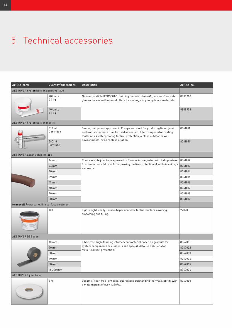
5 Technical accessories
Article-name Quantity/dimensions Description Article-no.
AESTUVER fire-protection adhesive 1300
20 Units à 1 kg
Noncombustible (EN13501-1, building material class A1), solvent-free water glass adhesive with mineral fillers for sealing and joining board materials.
8809903
40 Unitsà 1 kg
8809904
AESTUVER fire-protection mastic
310 ml Cartridge
Sealing compound approved in Europe and used for producing linear joint seals or fire barriers. Can be used as sealant, filler compound or coating material, as waterproofing for fire-protection joints in outdoor or wet environments, or as cable insulation.
8061011
580 mlFilm tube
8061020
AESTUVER expansion joint tape
16 mm Compressible joint tape approved in Europe, impregnated with halogen-free fire-protection additives for improving the fire-protection of joints in ceilings and walls.
8061012
24 mm 8061013
30 mm 8061014
39 mm 8061015
49 mm 8061016
60 mm 8061017
70 mm 8061018
80 mm 8061019
fermacell Powerpanel fine surface treatment
10 l Lightweight, ready-to-use dispersion filler for full-surface covering, smoothing and filling.
79090
AESTUVER DSB tape
10 mm Fiber-free, high-foaming intumescent material based on graphite for system components or elements and special, detailed solutions for structural fire-protection.
8062001
20 mm 8062002
30 mm 8062003
40 mm 8062004
50 mm 8062005
to 300 mm 8062006
AESTUVER T joint tape
5 m Ceramic-fiber-free joint tape, guarantees outstanding thermal stability with a melting point of over 1 330°C.
8063002
14
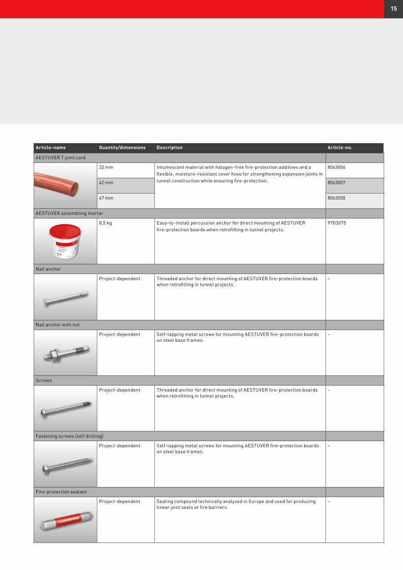
Article-name Quantity/dimensions Description Article-no.
AESTUVER T joint cord
32 mm Intumescent material with halogen-free fire-protection additives and a flexible, moisture-resistant cover hose for strengthening expansion joints in tunnel construction while ensuring fire-protection.
8063006
42 mm 8063007
47 mm 8063008
AESTUVER assembling mortar
8,5 kg Easy-to-install percussion anchor for direct mounting of AESTUVER fire-protection boards when retrofitting in tunnel projects.
9703075
Nail anchor
Project-dependent Threaded anchor for direct mounting of AESTUVER fire-protection boards when retrofitting in tunnel projects.
–
Nail anchor with nut
Project-dependent Self-tapping metal screws for mounting AESTUVER fire-protection boards on steel base frames.
–
Screws
Project-dependent Threaded anchor for direct mounting of AESTUVER fire-protection boards when retrofitting in tunnel projects.
–
Fastening screws (self drilling)
Project-dependent Self-tapping metal screws for mounting AESTUVER fire-protection boards on steel base frames.
–
Fire-protection sealant
Project-dependent Sealing compound technically analyzed in Europe and used for producing linear joint seals or fire barriers.
–
15
6 Installation instructions for AESTUVER board materials
6.1 General
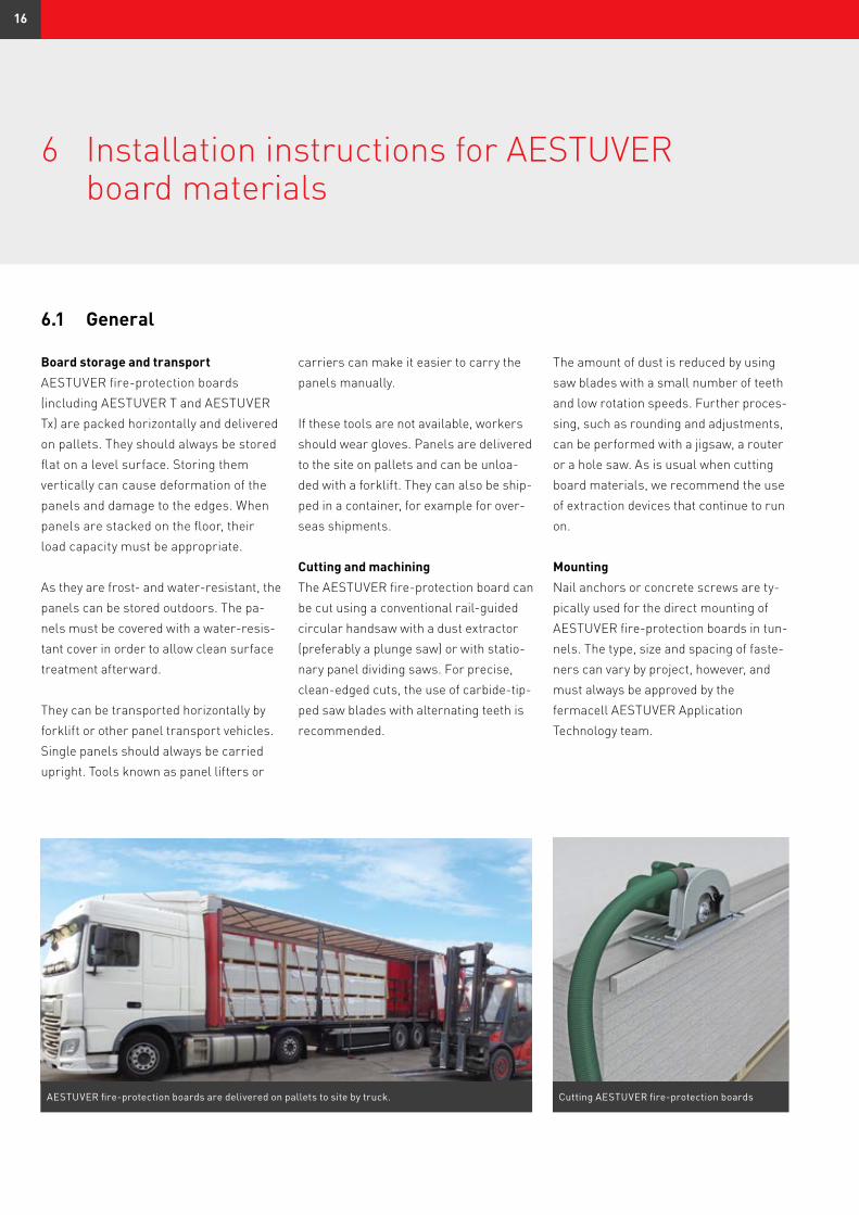
Board storage and transportAESTUVER fire-protection boards (including AESTUVER T and AESTUVER Tx) are packed horizontally and delivered on pallets. They should always be stored flat on a level surface. Storing them vertically can cause deformation of the panels and damage to the edges. When panels are stacked on the floor, their load capacity must be appropriate.
As they are frost- and water-resistant, the panels can be stored outdoors. The pa-nels must be covered with a water-resis-tant cover in order to allow clean surface treatment afterward.
They can be transported horizontally by forklift or other panel transport vehicles. Single panels should always be carried upright. Tools known as panel lifters or
carriers can make it easier to carry the panels manually.
If these tools are not available, workers should wear gloves. Panels are delivered to the site on pallets and can be unloa-ded with a forklift. They can also be ship-ped in a container, for example for over-seas shipments.
Cutting and machining The AESTUVER fire-protection board can be cut using a conventional rail-guided circular handsaw with a dust extractor (preferably a plunge saw) or with statio-nary panel dividing saws. For precise, clean-edged cuts, the use of carbide-tip-ped saw blades with alternating teeth is recommended.
The amount of dust is reduced by using saw blades with a small number of teeth and low rotation speeds. Further proces-sing, such as rounding and adjustments, can be performed with a jigsaw, a router or a hole saw. As is usual when cutting board materials, we recommend the use of extraction devices that continue to run on.
MountingNail anchors or concrete screws are ty-pically used for the direct mounting of AESTUVER fire-protection boards in tun-nels. The type, size and spacing of faste-ners can vary by project, however, and must always be approved by the fermacell AESTUVER Application Technology team.
AESTUVER fire-protection boards are delivered on pallets to site by truck. Cutting AESTUVER fire-protection boards
16
Backing strips can be fixed to the AESTUVER fire-protection boards using standard commercial steel staples, which makes it possible to prefabricate individual cladding elements.
Joint designAESTUVER fire-protection boards are butt-jointed (gap width ≤2 mm). Where necessary, wider gaps can be filled with AESTUVER assembling mortar or a simi-lar material. Approval must always be obtained from the fermacell AESTUVER Application Technology team.
Surface treatmentThe smooth surface of AESTUVER fire-protection boards makes them ideal for painting or coating.
The visible side of the AESTUVER fire-protection board has a smooth surface; the alkaline base thus does not need any filling prior to final surface finishing. However, we do recommend undercoa-ting with a base primer if the surface is to be painted or varnished. Dispersion-, resin- or acrylic-based fillers, paints and
varnishes from typical commercial manufacturers can be used.
For special applications, the panel surface may need to be impregnated with alkali-resistant products. Please follow the manufacturer’s instructions when applying the coating.
Panels must be dry and free of dust and grease prior to surface treatment. Coatings up to 0.5 mm thick will not infringe fire safety requirements with respect to fire resistance classification.
For esthetic reasons, fire-protection cladding in tunnel areas that are cons-tantly exposed to weather can be coated in order to prevent uneven penetration of moisture. It is highly recommended that panels and panel edges that are exposed to water spray be coated – for example, in tunnel mouths and at entry points. The length of the area to be coated must be defined for each specific project. It depends, in particular, on the distance that melt water is carried into the tunnel. In general, it is recommended that these
areas be coated up to a height of 3 me-ters above the surface of the roadway.
For frost and road salt resistance in road tunnels, AESTUVER fire-protection boards must be surface-coated. Approp-riate solutions must be clarified on a project-specific basis and approved by the fermacell AESTUVER Application Technology team.
For environments with demanding corrosion protection requirements, the substructure
and fixing must meet special quality requirements. The planning engineer must factor
in these requirements when stipulating which building materials are to be used and
determining appropriate protective measures.
17
6.2 Installation instructions for fire-protection cladding
on concrete
The AESTUVER fire-protection boards and backing strips must be clean, dry and free of dust.
Structural conditions in the tunnel (such as joints or integral components) must be considered in detail during planning and installation of the fire-protection boards.
A gap must be left around adjacent components in order to prevent climate variations from causing any movement of the structure or board materials..
AESTUVER fire-protection boards are installed in the shell construction with butt joints. All butt joints are then covered with backing strips(lengthwise and crosswise).
n Width: 100 mmn Thickness: 10 mm This protects the bottom of the panel (side that is visible in the tunnel) from being contaminated with wet cement.
n Length 1 = 625 mm The backing strip is applied to the joints on the short side of the panels (625 mm), offset 50 mm from the long edge of the panel. Adjacent backing strips must be spaced apart by 2 mm.
n Length 2 = 1 198 mm The backing strip is abutted to the shorter backing strips along the joints on the longer side of the board (1 300 mm). Adjacent backing strips must be spaced apart by 2 mm on both sides.
Each backing strip is fixed with staples (made of rustproof steel). n Staple spacing: approx. 50 mmn Staple length: Thickness of the backing strips + board thickness – 5 mm
RepairsMinor damage to AESTUVER fire-protec-tion boards that occurs during handling (such as minor spalling on the panel edges or fixings), damage to the surface (such as scratches) or closure of installa-tion cut-outs in the panels (such as for bolted connections at wall corners) can be repaired with AESTUVER assembling mortar. Small holes (≤8 mm) can also be filled with AESTUVER fire-protection mastic.
CleaningAESTUVER fire-protection boards can be cleaned using conventional cleaning me-thods, such as high-pressure water jets, steam jets or brushes. When using high-pressure water jets, we recommend the following distances between the nozzle and the panel surface:n Distance ≥50 cm for 100 barn Distance ≥20 cm for 20 bar
AESTUVER fire-protection boards requi-re no additional coating or hydrophobic treatment for the cleaning methods listed above.
DisposalAESTUVER fire-protection boards are a mineral building material with no compo-nents that are dangerous to health or groundwater; it can therefore be dispo-sed of at construction-waste landfill si-tes. Waste code (EWC): 170101 (concrete)
It is recommended to start with 625 mm long backing strips.
The smooth, printed side remains visible during the preparation process. The nonprinted side faces the interior of the tunnel (i.e., the roadway).
18
In order to mount AESTUVER fire-protection boards securely, uneven base surfaces must be smoothed out in the area of the mounting points as needed. Backing strips can be used for this purpose or, for smaller areas, AESTUVER assembling mortar can also be used.
6.3 Handling instructions for retrofitted fire-protection cladding
(direct mounting)
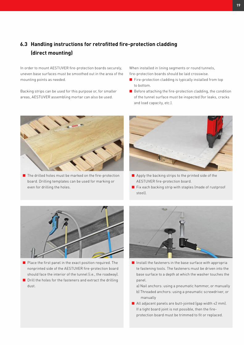
n The drilled holes must be marked on the fire-protection board. Drilling templates can be used for marking or even for drilling the holes.
When installed in lining segments or round tunnels, fire-protection boards should be laid crosswise.n Fire-protection cladding is typically installed from top to bottom.n Before attaching the fire-protection cladding, the condition of the tunnel surface must be inspected (for leaks, cracks and load capacity, etc.).
n Apply the backing strips to the printed side of the AESTUVER fire-protection board.n Fix each backing strip with staples (made of rustproof steel).
n Place the first panel in the exact position required. The nonprinted side of the AESTUVER fire-protection board should face the interior of the tunnel (i.e., the roadway).n Drill the holes for the fasteners and extract the drilling dust.
n Install the fasteners in the base surface with appropria te fastening tools. The fasteners must be driven into the base surface to a depth at which the washer touches the panel. a) Nail anchors: using a pneumatic hammer, or manually b) Threaded anchors: using a pneumatic screwdriver, or manuallyn All adjacent panels are butt-jointed (gap width ≤2 mm). If a tight board joint is not possible, then the fire- protection board must be trimmed to fit or replaced.
19
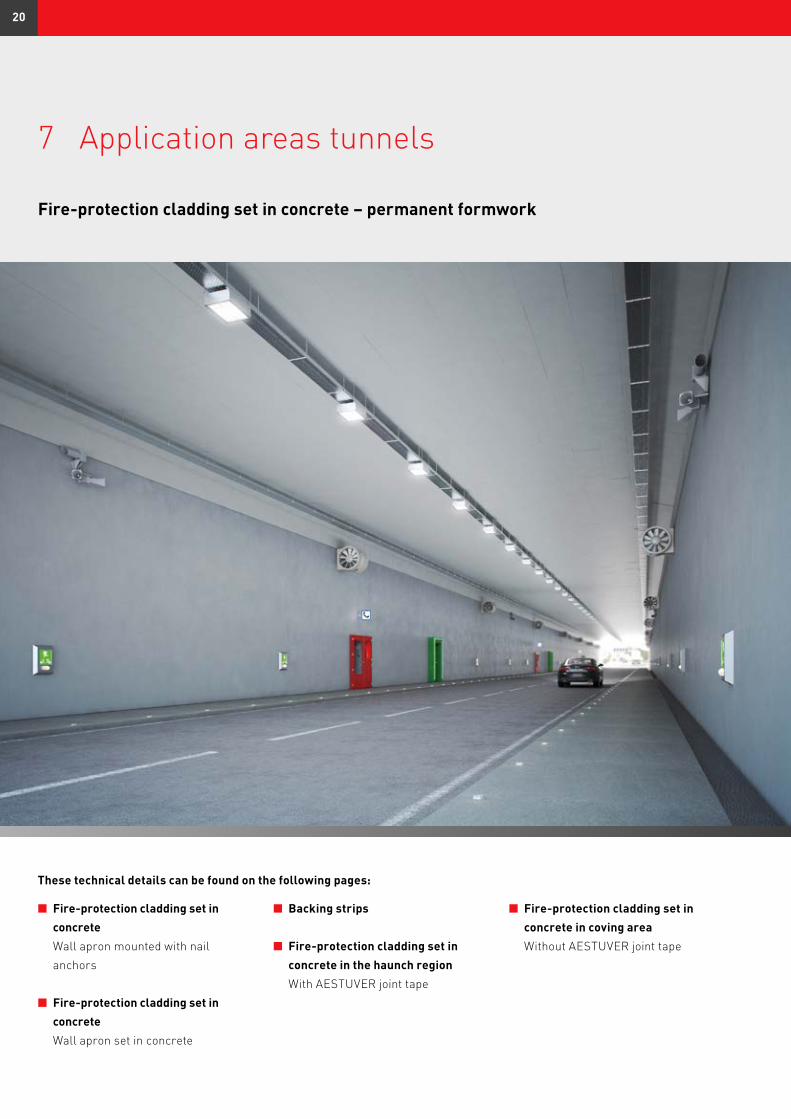
7 Application areas tunnels
n Fire-protection cladding set in concrete Wall apron mounted with nail anchors
n Fire-protection cladding set in concrete Wall apron set in concrete
n Backing strips
n Fire-protection cladding set in concrete in the haunch region With AESTUVER joint tape
These technical details can be found on the following pages:
n Fire-protection cladding set in concrete in coving area Without AESTUVER joint tape
Fire-protection cladding set in concrete – permanent formwork
20
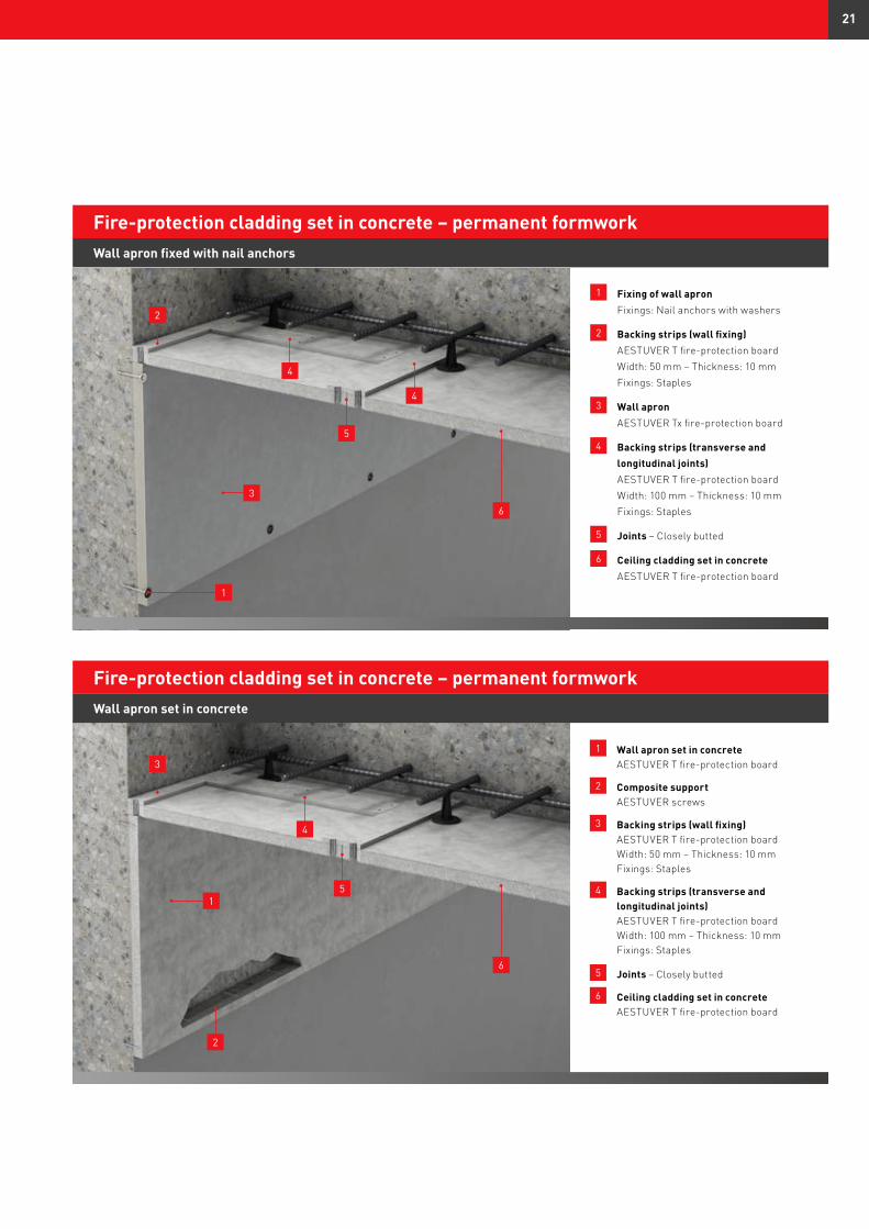
1 Fixing of wall apron Fixings: Nail anchors with washers
2 Backing strips (wall fixing) AESTUVER T fire-protection board Width: 50 mm – Thickness: 10 mm Fixings: Staples
3 Wall apron AESTUVER Tx fire-protection board
4 Backing strips (transverse and longitudinal joints) AESTUVER T fire-protection board Width: 100 mm – Thickness: 10 mm Fixings: Staples
5 Joints – Closely butted
6 Ceiling cladding set in concrete AESTUVER T fire-protection board
Wall apron fixed with nail anchors
Fire-protection cladding set in concrete – permanent formwork
1 Wall apron set in concrete AESTUVER T fire-protection board
2 Composite support AESTUVER screws
3 Backing strips (wall fixing) AESTUVER T fire-protection board Width: 50 mm – Thickness: 10 mm Fixings: Staples
4 Backing strips (transverse and longitudinal joints) AESTUVER T fire-protection board Width: 100 mm – Thickness: 10 mm Fixings: Staples
5 Joints – Closely butted
6 Ceiling cladding set in concrete AESTUVER T fire-protection board
Wall apron set in concrete
Fire-protection cladding set in concrete – permanent formwork
1
5
2
4
4
6
3
1
2
3
5
4
6
21
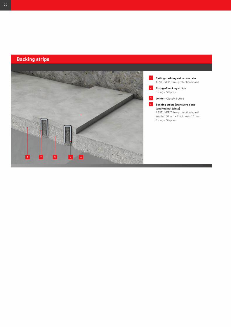
1 Ceiling cladding set in concrete AESTUVER T fire-protection board
2 Fixing of backing strips Fixings: Staples
3 Joints – Closely butted
4 Backing strips (transverse and longitudinal joints) AESTUVER T fire-protection board Width: 100 mm – Thickness: 10 mm Fixings: Staples
Backing strips
1 2 2 43
22
1
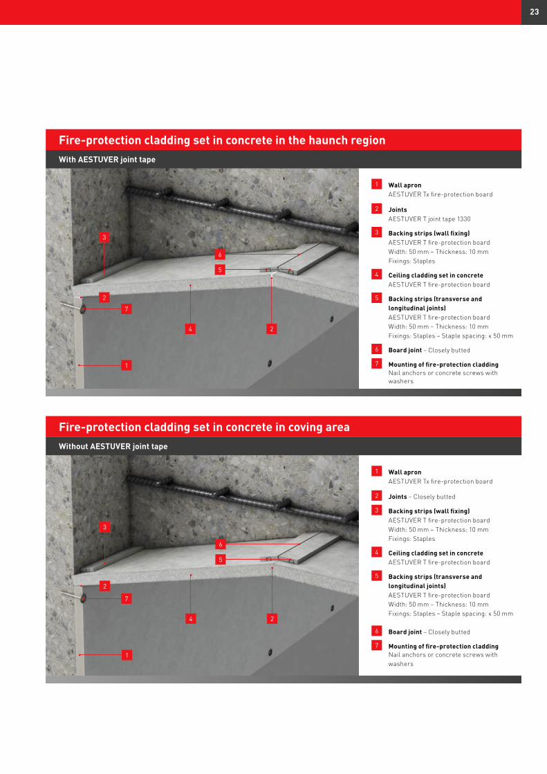
1 Wall apron AESTUVER Tx fire-protection board
2 Joints AESTUVER T joint tape 1330
3 Backing strips (wall fixing) AESTUVER T fire-protection board Width: 50 mm – Thickness: 10 mm Fixings: Staples
4 Ceiling cladding set in concrete AESTUVER T fire-protection board
5 Backing strips (transverse and longitudinal joints) AESTUVER T fire-protection board Width: 50 mm – Thickness: 10 mm Fixings: Staples – Staple spacing: ≤ 50 mm
6 Board joint – Closely butted
7 Mounting of fire-protection cladding Nail anchors or concrete screws with washers
With AESTUVER joint tape
Fire-protection cladding set in concrete in the haunch region
2
2
1 Wall apron AESTUVER Tx fire-protection board
2 Joints – Closely butted
3 Backing strips (wall fixing) AESTUVER T fire-protection board Width: 50 mm – Thickness: 10 mm Fixings: Staples
4 Ceiling cladding set in concrete AESTUVER T fire-protection board
5 Backing strips (transverse and longitudinal joints) AESTUVER T fire-protection board Width: 50 mm – Thickness: 10 mm Fixings: Staples – Staple spacing: ≤ 50 mm
6 Board joint – Closely butted
7 Mounting of fire-protection cladding Nail anchors or concrete screws with washers
Without AESTUVER joint tape
Fire-protection cladding set in concrete in coving area
5
6
3
1
2
2
5
6
3
4
4
7
7
23
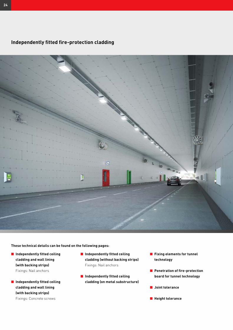
Independently fitted fire-protection cladding
n Independently fitted ceiling cladding and wall lining (with backing strips) Fixings: Nail anchors
n Independently fitted ceiling cladding and wall lining (with backing strips) Fixings: Concrete screws
n Independently fitted ceiling cladding (without backing strips) Fixings: Nail anchors
n Independently fitted ceiling cladding (on metal substructure)
n Fixing elements for tunnel technology
n Penetration of fire-protection board for tunnel technology
n Joint tolerance
n Height tolerance
These technical details can be found on the following pages:
24
1
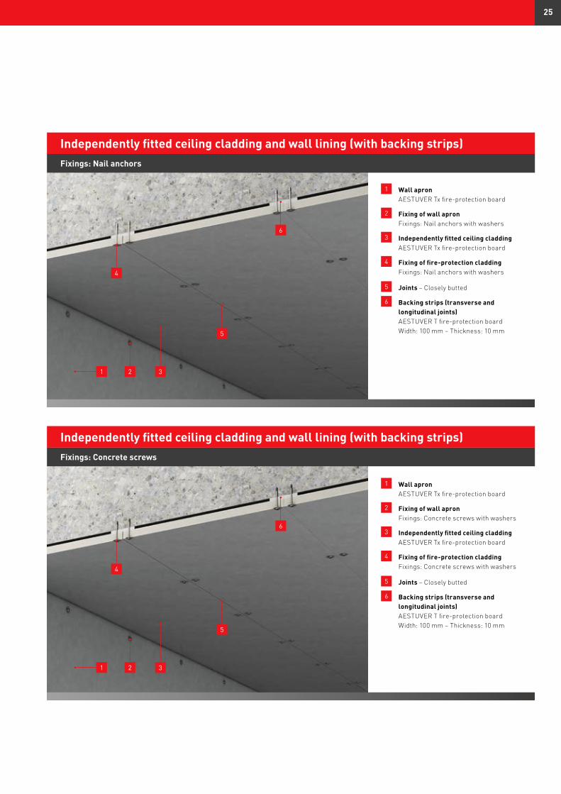
1 Wall apron AESTUVER Tx fire-protection board
2 Fixing of wall apron Fixings: Nail anchors with washers
3 Independently fitted ceiling cladding AESTUVER Tx fire-protection board
4 Fixing of fire-protection cladding Fixings: Nail anchors with washers
5 Joints – Closely butted
6 Backing strips (transverse and longitudinal joints) AESTUVER T fire-protection board Width: 100 mm – Thickness: 10 mm
Fixings: Nail anchors
Independently fitted ceiling cladding and wall lining (with backing strips)
2
1 Wall apron AESTUVER Tx fire-protection board
2 Fixing of wall apron Fixings: Concrete screws with washers
3 Independently fitted ceiling cladding AESTUVER Tx fire-protection board
4 Fixing of fire-protection cladding Fixings: Concrete screws with washers
5 Joints – Closely butted
6 Backing strips (transverse and longitudinal joints) AESTUVER T fire-protection board Width: 100 mm – Thickness: 10 mm
Fixings: Concrete screws
Independently fitted ceiling cladding and wall lining (with backing strips)
3
4
5
6
1 2 3
4
5
6
25
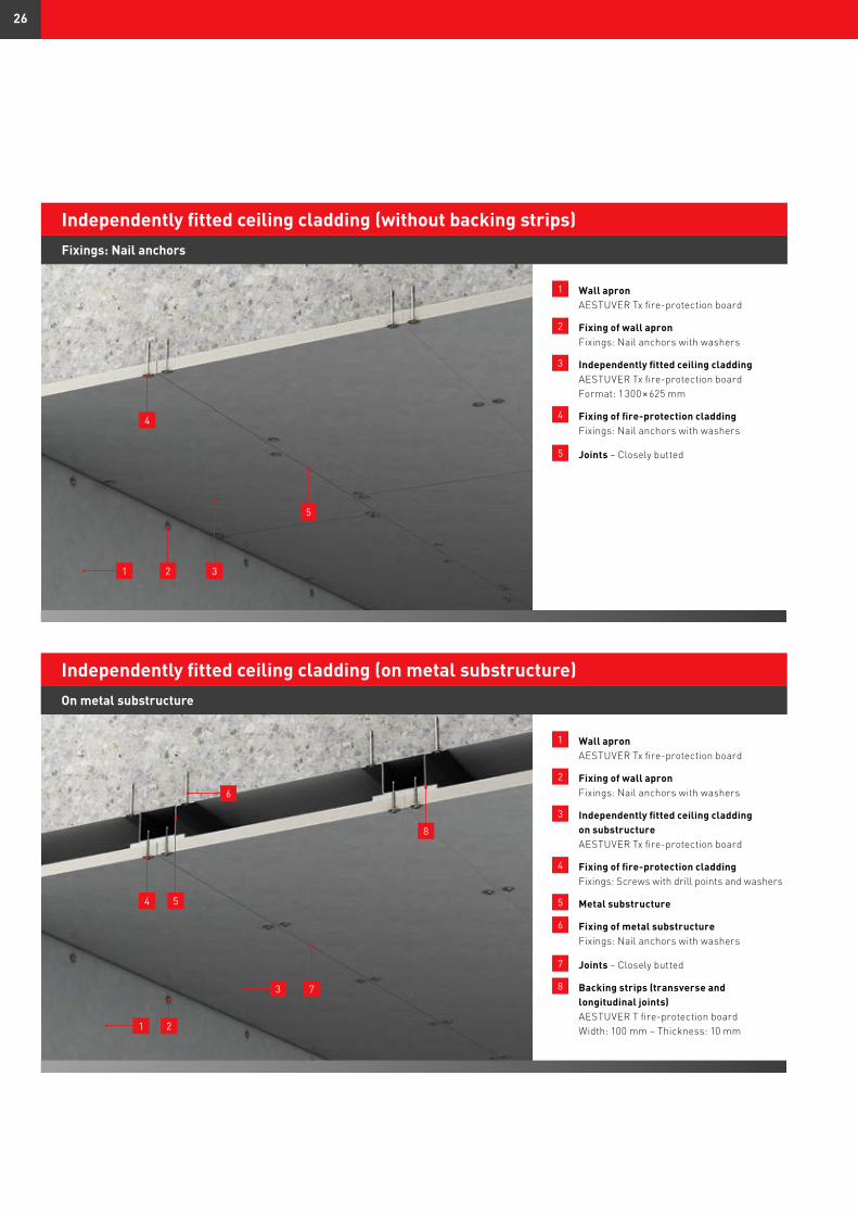
1 Wall apron AESTUVER Tx fire-protection board
2 Fixing of wall apron Fixings: Nail anchors with washers
3 Independently fitted ceiling cladding AESTUVER Tx fire-protection board Format: 1 300 × 625 mm
4 Fixing of fire-protection cladding Fixings: Nail anchors with washers
5 Joints – Closely butted
Fixings: Nail anchors
Independently fitted ceiling cladding (without backing strips)
1 Wall apron AESTUVER Tx fire-protection board
2 Fixing of wall apron Fixings: Nail anchors with washers
3 Independently fitted ceiling cladding on substructure AESTUVER Tx fire-protection board
4 Fixing of fire-protection cladding Fixings: Screws with drill points and washers
5 Metal substructure
6 Fixing of metal substructure Fixings: Nail anchors with washers
7 Joints – Closely butted
8 Backing strips (transverse and longitudinal joints) AESTUVER T fire-protection board Width: 100 mm – Thickness: 10 mm
Independently fitted ceiling cladding (on metal substructure)
4
7
5
6
8
1 2 3
4
5
3
1
On metal substructure
2
26
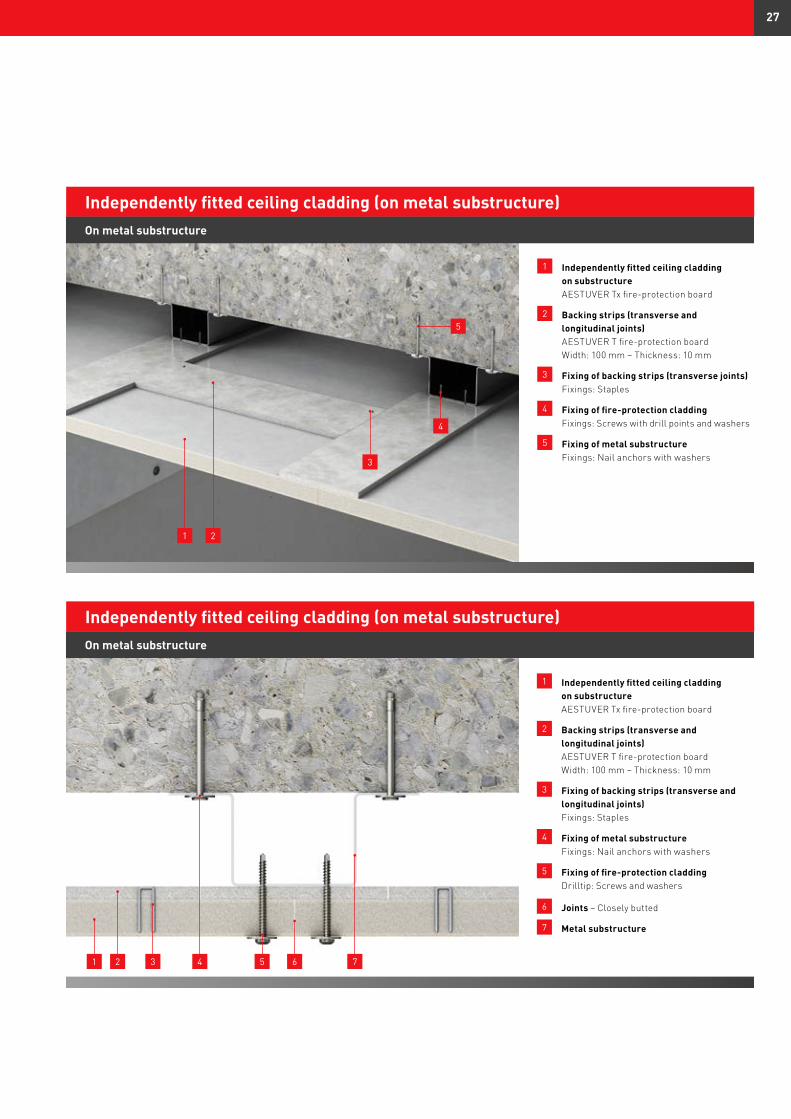
1 Independently fitted ceiling cladding on substructure AESTUVER Tx fire-protection board
2 Backing strips (transverse and longitudinal joints) AESTUVER T fire-protection board Width: 100 mm – Thickness: 10 mm
3 Fixing of backing strips (transverse joints) Fixings: Staples
4 Fixing of fire-protection cladding Fixings: Screws with drill points and washers
5 Fixing of metal substructure Fixings: Nail anchors with washers
Independently fitted ceiling cladding (on metal substructure)
1
1 Independently fitted ceiling cladding on substructure AESTUVER Tx fire-protection board
2 Backing strips (transverse and longitudinal joints) AESTUVER T fire-protection board Width: 100 mm – Thickness: 10 mm
3 Fixing of backing strips (transverse and longitudinal joints) Fixings: Staples
4 Fixing of metal substructure Fixings: Nail anchors with washers
5 Fixing of fire-protection cladding Drilltip: Screws and washers
6 Joints – Closely butted
7 Metal substructure
Independently fitted ceiling cladding (on metal substructure)
3
5
2
4
1 2 4 5 6 7
On metal substructure
On metal substructure
3
27
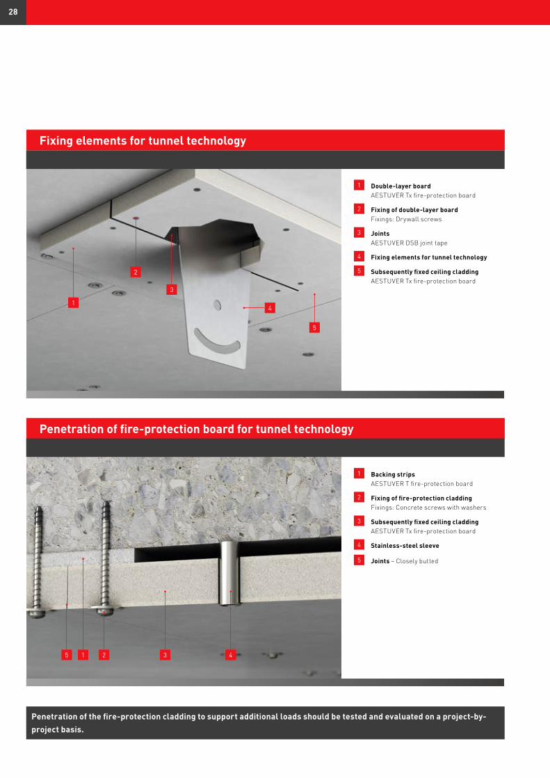
Penetration of the fire-protection cladding to support additional loads should be tested and evaluated on a project-by-project basis.
1 Double-layer board AESTUVER Tx fire-protection board
2 Fixing of double-layer board Fixings: Drywall screws
3 Joints AESTUVER DSB joint tape
4 Fixing elements for tunnel technology
5 Subsequently fixed ceiling cladding AESTUVER Tx fire-protection board
Fixing elements for tunnel technology
1 Backing strips AESTUVER T fire-protection board
2 Fixing of fire-protection cladding Fixings: Concrete screws with washers
3 Subsequently fixed ceiling cladding AESTUVER Tx fire-protection board
4 Stainless-steel sleeve
5 Joints – Closely butted
Penetration of fire-protection board for tunnel technology
1
2
3
4
5
5 1 2 43
28
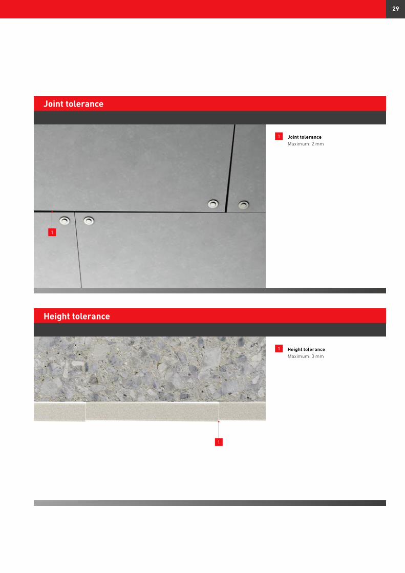
1 Joint tolerance Maximum: 2 mm
Joint tolerance
1 Height tolerance Maximum: 3 mm
Height tolerance
1
1
29
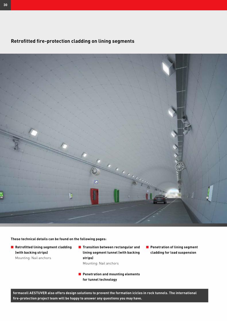
n Retrofitted lining segment cladding (with backing strips) Mounting: Nail anchors
n Transition between rectangular and lining segment tunnel (with backing strips) Mounting: Nail anchors
n Penetration and mounting elements for tunnel technology
These technical details can be found on the following pages:
Retrofitted fire-protection cladding on lining segments
fermacell AESTUVER also offers design solutions to prevent the formation icicles in rock tunnels. The international fire-protection project team will be happy to answer any questions you may have.
n Penetration of lining segment cladding for load suspension
30
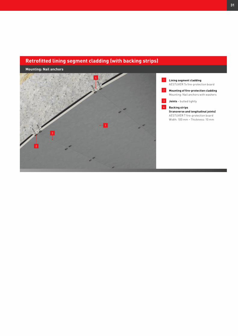
1 Lining segment cladding AESTUVER Tx fire-protection board
2 Mounting of fire-protection cladding Mounting: Nail anchors with washers
3 Joints – butted tightly
4 Backing strips (transverse and longitudinal joints) AESTUVER T fire-protection board Width: 100 mm – Thickness: 10 mm
Retrofitted lining segment cladding (with backing strips)
2
1
3
Mounting: Nail anchors
4
31
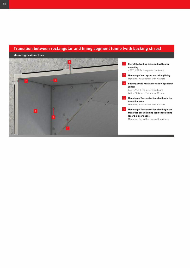
1 Retrofitted ceiling lining and wall apron mounting AESTUVER Tx fire-protection board
2 Mounting of wall apron and ceiling lining Mounting: Nail anchors with washers
3 Backing strips (transverse and longitudinal joints) AESTUVER T fire-protection board Width: 100 mm – Thickness: 10 mm
4 Mounting of fire-protection cladding in the transition area Mounting: Nail anchors with washers
5 Mounting of fire-protection cladding in the transition area on lining segment cladding (board in board edge) Mounting: Drywall screws with washers
Transition between rectangular and lining segment tunne (with backing strips)Mounting: Nail anchors
3
5
4
1
12
32
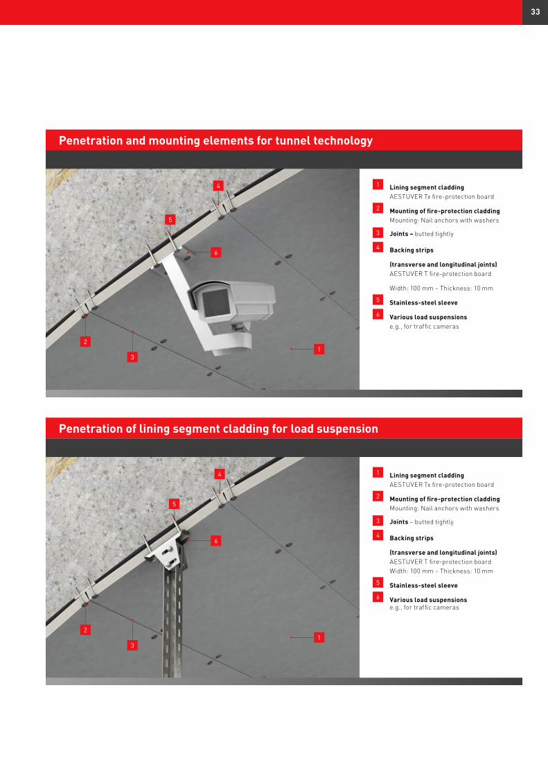
1 Lining segment cladding AESTUVER Tx fire-protection board
2 Mounting of fire-protection cladding Mounting: Nail anchors with washers
3 Joints – butted tightly
4 Backing strips
(transverse and longitudinal joints) AESTUVER T fire-protection board
Width: 100 mm – Thickness: 10 mm
5 Stainless-steel sleeve
6 Various load suspensions e.g., for traffic cameras
Penetration and mounting elements for tunnel technology
1 Lining segment cladding AESTUVER Tx fire-protection board
2 Mounting of fire-protection cladding Mounting: Nail anchors with washers
3 Joints – butted tightly
4 Backing strips
(transverse and longitudinal joints) AESTUVER T fire-protection board Width: 100 mm – Thickness: 10 mm
5 Stainless-steel sleeve
6 Various load suspensions e.g., for traffic cameras
Penetration of lining segment cladding for load suspension
2
3
6
1
4
5
2
3
6
1
4
5
33
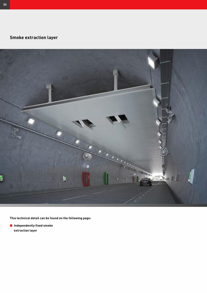
Smoke extraction layer
n Independently fixed smoke extraction layer
This technical detail can be found on the following page:
34
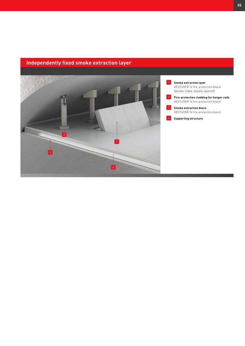
1 Smoke extraction layer AESTUVER Tx fire-protection board (double-sided, double-layered)
2 Fire-protection cladding for hanger rods AESTUVER Tx fire-protection board
3 Smoke extraction doors AESTUVER Tx fire-protection board
4 Supporting structure
Independently fixed smoke extraction layer
2
3
4
1
35
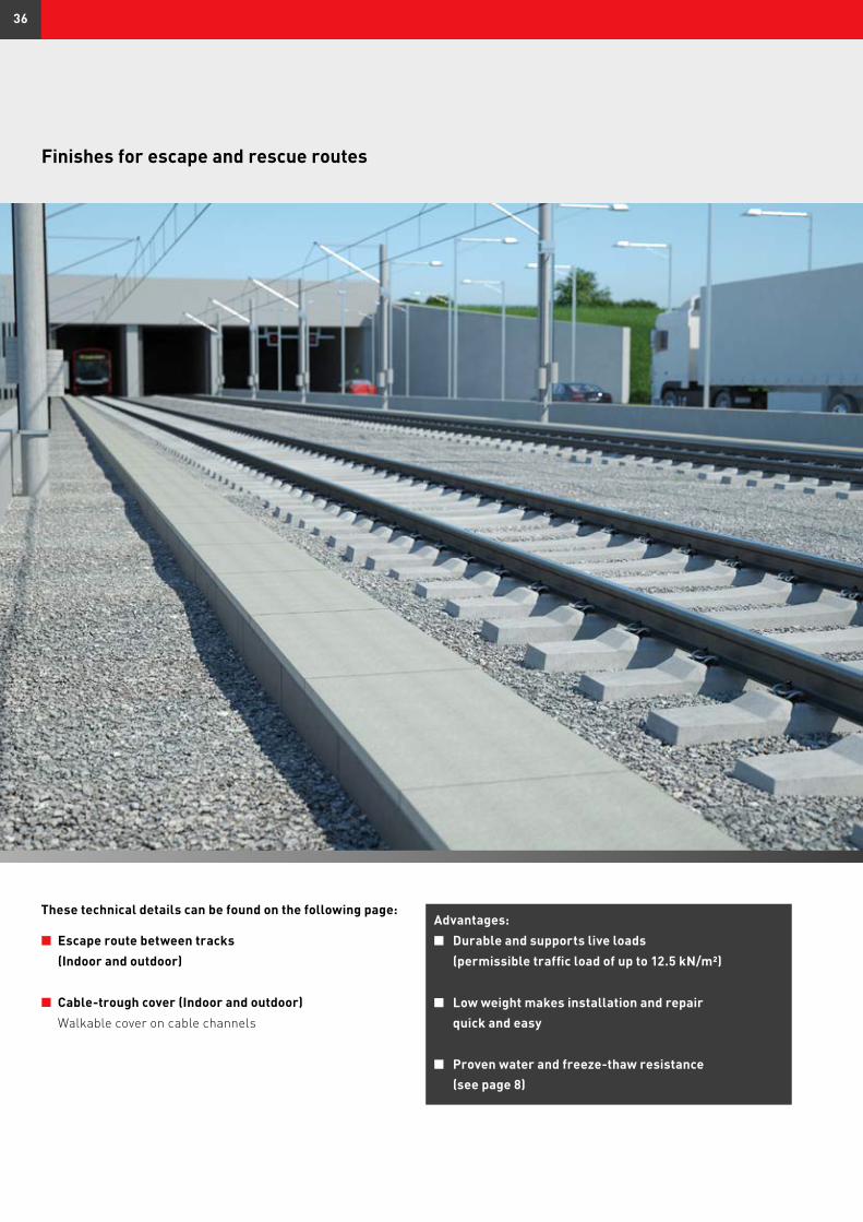
Finishes for escape and rescue routes
n Escape route between tracks (Indoor and outdoor)
n Cable-trough cover (Indoor and outdoor) Walkable cover on cable channels
These technical details can be found on the following page:Advantages:n Durable and supports live loads (permissible traffic load of up to 12.5 kN/m²)
n Low weight makes installation and repair quick and easy
n Proven water and freeze-thaw resistance (see page 8)
36
1
3
2
4
1
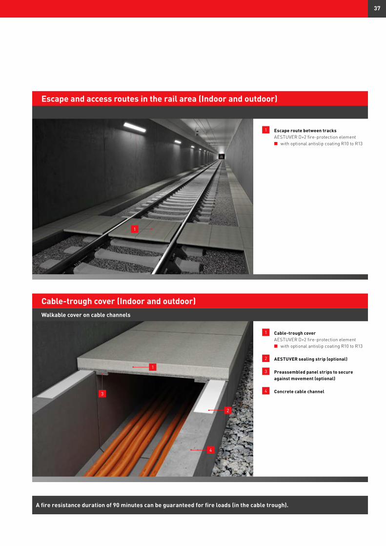
1 Escape route between tracks AESTUVER D+2 fire-protection element n with optional antislip coating R10 to R13
Escape and access routes in the rail area (Indoor and outdoor)
1 Cable-trough cover AESTUVER D+2 fire-protection element n with optional antislip coating R10 to R13
2 AESTUVER sealing strip (optional)
3 Preassembled panel strips to secure against movement (optional)
4 Concrete cable channel
Cable-trough cover (Indoor and outdoor)Walkable cover on cable channels
A fire resistance duration of 90 minutes can be guaranteed for fire loads (in the cable trough).
37
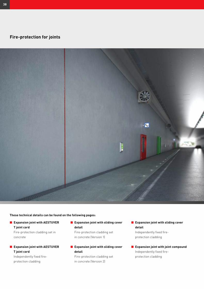
Fire-protection for joints
n Expansion joint with AESTUVER T joint cord Fire-protection cladding set in concrete
n Expansion joint with AESTUVER T joint cord Independently fixed fire- protection cladding
n Expansion joint with sliding cover detail Fire-protection cladding set in concrete (Version 1)
n Expansion joint with sliding cover detail Fire-protection cladding set in concrete (Version 2)
These technical details can be found on the following pages:
n Expansion joint with sliding cover detail Independently fixed fire- protection cladding
n Expansion joint with joint compound Independently fixed fire- protection cladding
38
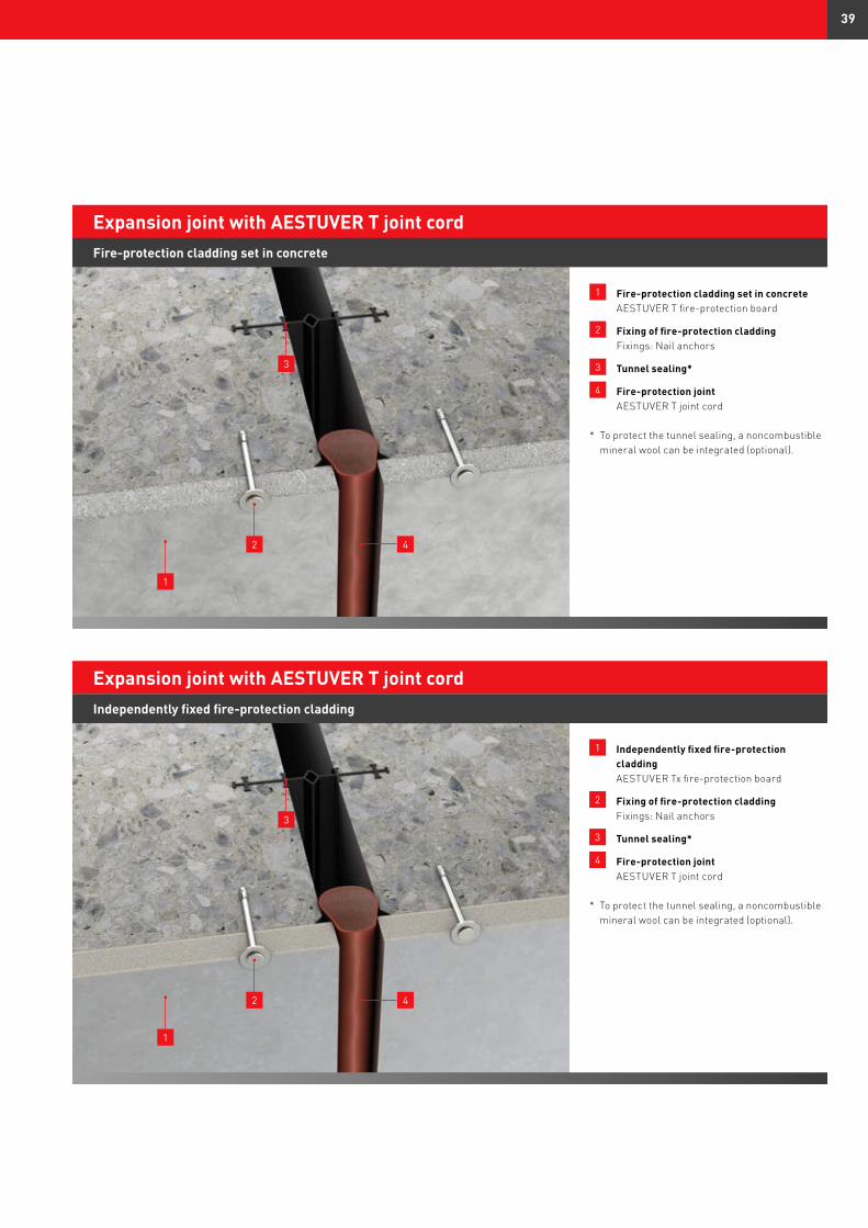
1 Fire-protection cladding set in concrete AESTUVER T fire-protection board
2 Fixing of fire-protection cladding Fixings: Nail anchors
3 Tunnel sealing*
4 Fire-protection joint AESTUVER T joint cord
* To protect the tunnel sealing, a noncombustible mineral wool can be integrated (optional).
Expansion joint with AESTUVER T joint cord
1 Independently fixed fire-protection cladding AESTUVER Tx fire-protection board
2 Fixing of fire-protection cladding Fixings: Nail anchors
3 Tunnel sealing*
4 Fire-protection joint AESTUVER T joint cord
* To protect the tunnel sealing, a noncombustible mineral wool can be integrated (optional).
Expansion joint with AESTUVER T joint cord
2
1
3
4
Fire-protection cladding set in concrete
Independently fixed fire-protection cladding
2
1
3
4
39
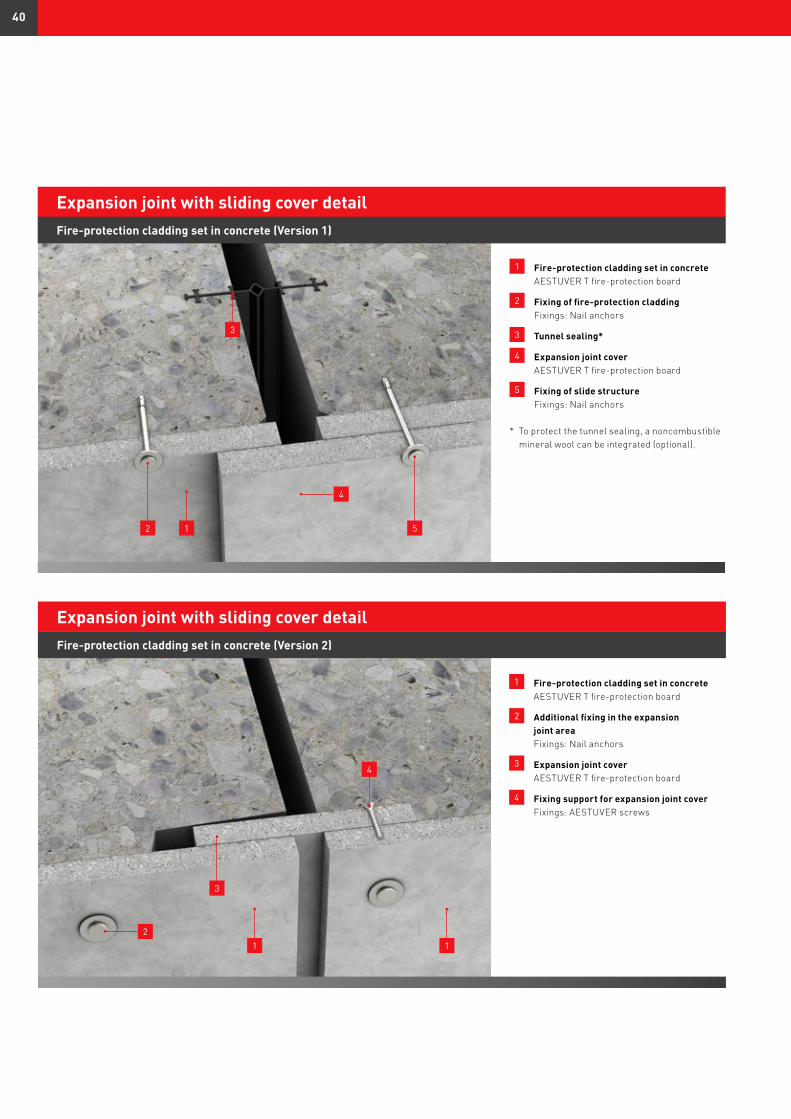
1 Fire-protection cladding set in concrete AESTUVER T fire-protection board
2 Additional fixing in the expansion joint area Fixings: Nail anchors
3 Expansion joint cover AESTUVER T fire-protection board
4 Fixing support for expansion joint cover Fixings: AESTUVER screws
Expansion joint with sliding cover detail
3
2
1 Fire-protection cladding set in concrete AESTUVER T fire-protection board
2 Fixing of fire-protection cladding Fixings: Nail anchors
3 Tunnel sealing*
4 Expansion joint cover AESTUVER T fire-protection board
5 Fixing of slide structure Fixings: Nail anchors
* To protect the tunnel sealing, a noncombustible mineral wool can be integrated (optional).
Expansion joint with sliding cover detailFire-protection cladding set in concrete (Version 1)
1
4
12
3
4
5
Fire-protection cladding set in concrete (Version 2)
1
40
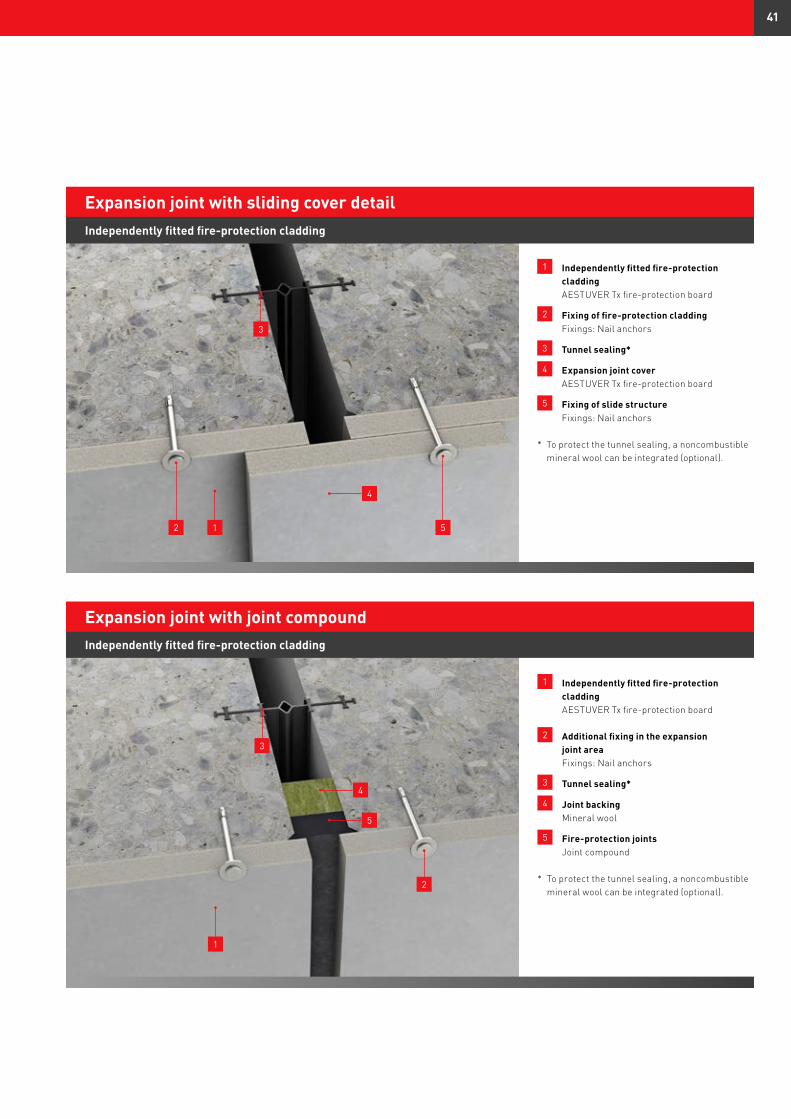
1 Independently fitted fire-protection cladding AESTUVER Tx fire-protection board
2 Fixing of fire-protection cladding Fixings: Nail anchors
3 Tunnel sealing*
4 Expansion joint cover AESTUVER Tx fire-protection board
5 Fixing of slide structure Fixings: Nail anchors
* To protect the tunnel sealing, a noncombustible mineral wool can be integrated (optional).
Expansion joint with sliding cover detailIndependently fitted fire-protection cladding
12
3
4
5
Expansion joint with joint compoundIndependently fitted fire-protection cladding
1 Independently fitted fire-protection cladding AESTUVER Tx fire-protection board
2 Additional fixing in the expansion joint area Fixings: Nail anchors
3 Tunnel sealing*
4 Joint backing Mineral wool
5 Fire-protection joints Joint compound
* To protect the tunnel sealing, a noncombustible mineral wool can be integrated (optional).
1
2
3
4
5
41
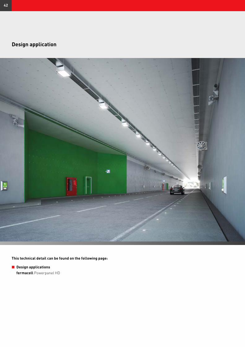
Design application
n Design applications fermacell Powerpanel HD
This technical detail can be found on the following page:
42
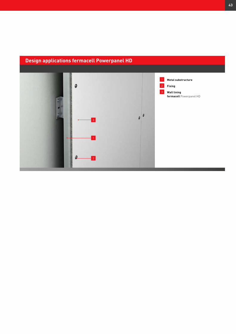
1 Metal substructure
2 Fixing
3 Wall lining fermacell Powerpanel HD
Design applications fermacell Powerpanel HD
1
2
3
43
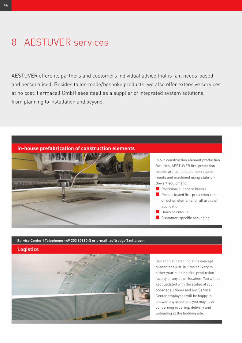
8 AESTUVER services
In-house prefabrication of construction elements
In our construction element production facilities, AESTUVER fire-protection boards are cut to customer require-ments and machined using state-of-the-art equipment.
Precision-cut board blanks Prefabricated fire-protection con-
struction elements for all areas of application
Holes or cutouts Customer-specific packaging
Service Center | Telephone: +49 203 60880-3 or e-mail: [email protected]
Logistics
Our sophisticated logistics concept guarantees just-in-time delivery to either your building site, production facility or any other location. You will be kept updated with the status of your order at all times and our Service Center employees will be happy to answer any questions you may have concerning ordering, delivery and unloading at the building site.
AESTUVER offers its partners and customers individual advice that is fair, needs-based
and personalised. Besides tailor-made/bespoke products, we also offer extensive services
at no cost. Fermacell GmbH sees itself as a supplier of integrated system solutions:
from planning to installation and beyond.
44

[email protected] | Subject: Tunnel fire-protection
Planning and project support
Planning to construct or already buil-ding a property? Searching for the right solution? We offer you free planning assistance and tailor-made system solutions for your building projects. A team of experienced engineers from Application Technology and Research and Development will assist you in solving individual challenges, so please take advantage of our many years of experience and expertise.
[email protected] | Subject: Tunnel fire-protection
Technical customer service at the building site
Our competent technical customer service team will be on hand to assist you at the building site. Whether you require assistance in design, planning or implementation, we can help.
[email protected] | Subject: Tunnel fire-protection
Exploratory tunnel-fire tests
Exploratory tunnel-fire tests can be performed in a modern, on-site furnace on both large and small scales, as required by the project.
Phot
o: ©
via
ppy
– Fo
tolia
.com
45
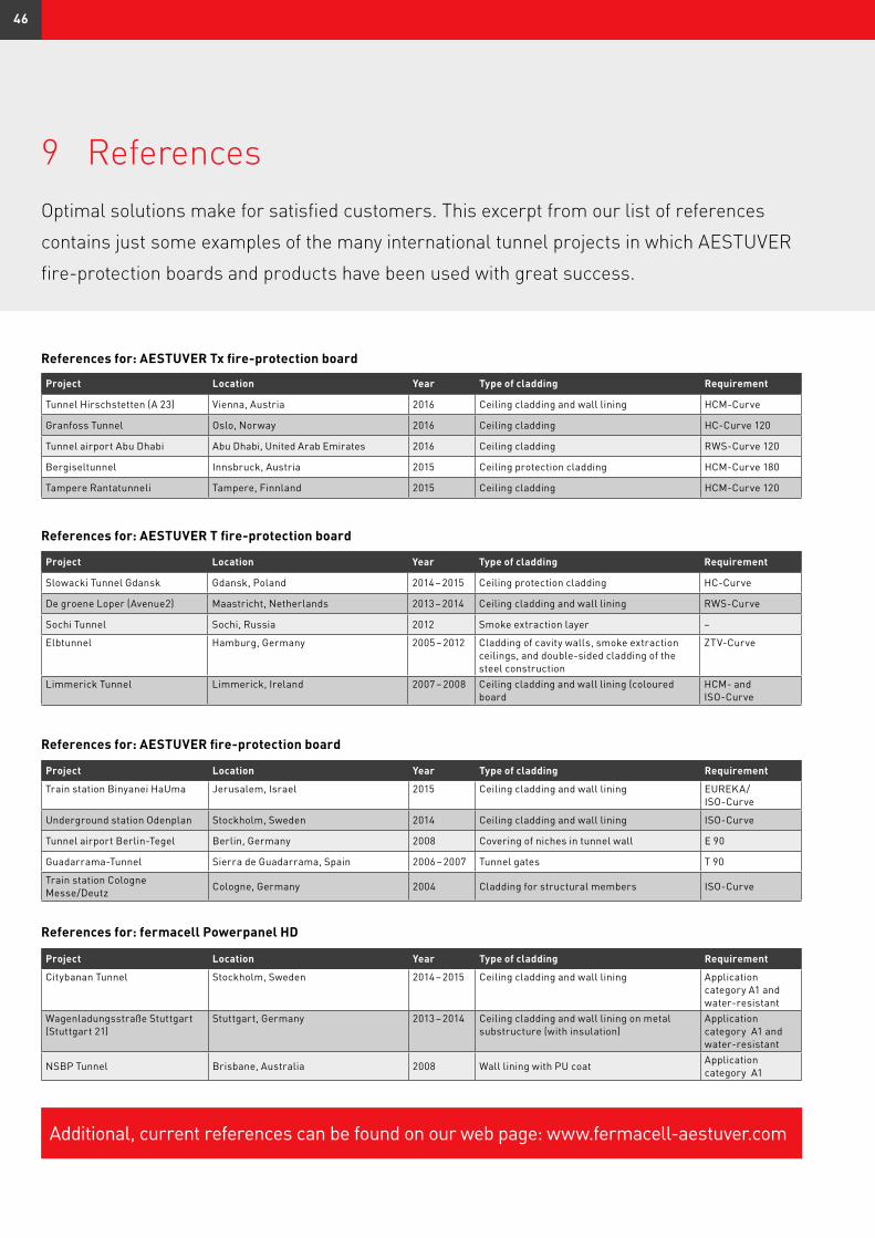
9 References
References for: AESTUVER Tx fire-protection board
Project Location Year Type of cladding Requirement
Tunnel Hirschstetten (A 23) Vienna, Austria 2016 Ceiling cladding and wall lining HCM-Curve
Granfoss Tunnel Oslo, Norway 2016 Ceiling cladding HC-Curve 120
Tunnel airport Abu Dhabi Abu Dhabi, United Arab Emirates 2016 Ceiling cladding RWS-Curve 120
Bergiseltunnel Innsbruck, Austria 2015 Ceiling protection cladding HCM-Curve 180
Tampere Rantatunneli Tampere, Finnland 2015 Ceiling cladding HCM-Curve 120
References for: AESTUVER T fire-protection board
Project Location Year Type of cladding Requirement
Slowacki Tunnel Gdansk Gdansk, Poland 2014 – 2015 Ceiling protection cladding HC-Curve
De groene Loper (Avenue2) Maastricht, Netherlands 2013 – 2014 Ceiling cladding and wall lining RWS-Curve
Sochi Tunnel Sochi, Russia 2012 Smoke extraction layer –
Elbtunnel Hamburg, Germany 2005 – 2012 Cladding of cavity walls, smoke extraction ceilings, and double-sided cladding of the steel construction
ZTV-Curve
Limmerick Tunnel Limmerick, Ireland 2007 – 2008 Ceiling cladding and wall lining (coloured board
HCM- and ISO-Curve
References for: AESTUVER fire-protection board
Project Location Year Type of cladding Requirement
Train station Binyanei HaUma Jerusalem, Israel 2015 Ceiling cladding and wall lining EUREKA/ ISO-Curve
Underground station Odenplan Stockholm, Sweden 2014 Ceiling cladding and wall lining ISO-Curve
Tunnel airport Berlin-Tegel Berlin, Germany 2008 Covering of niches in tunnel wall E 90
Guadarrama-Tunnel Sierra de Guadarrama, Spain 2006 – 2007 Tunnel gates T 90
Train station Cologne Messe/Deutz Cologne, Germany 2004 Cladding for structural members ISO-Curve
References for: fermacell Powerpanel HD
Project Location Year Type of cladding Requirement
Citybanan Tunnel Stockholm, Sweden 2014 – 2015 Ceiling cladding and wall lining Application category A1 and water-resistant
Wagenladungsstraße Stuttgart (Stuttgart 21)
Stuttgart, Germany 2013 – 2014 Ceiling cladding and wall lining on metal substructure (with insulation)
Application category A1 and water-resistant
NSBP Tunnel Brisbane, Australia 2008 Wall lining with PU coat Application category A1
Optimal solutions make for satisfied customers. This excerpt from our list of references
contains just some examples of the many international tunnel projects in which AESTUVER
fire-protection boards and products have been used with great success.
Additional, current references can be found on our web page: www.fermacell-aestuver.com
46

Notes
47

For additional information please visit the fermacell websitewww.fermacell-aestuver.com
Technical modifications subjectto changes. Last updated: 04/2016
The most recent edition applies.Should you require additionalinformation, please contact ourfermacell customer service.
fermacell® is a registered trademarkand a company of the XELLA group.
Fermacell GmbH
fermacell AESTUVER
Düsseldorfer Landstraße 395
D-47259 Duisburg
Germany
www.fermacell-aestuver.com
AT-003-00020/k/04.16