Fenger® FDM-8000i SD IP Digital Modulator - Kosmosat SA · The FDM-8000i SD IP Digital Modulator...
24
FDM-8000i Manual V1.0 INSTALLATION & CONFIGURATION MANUAL FDM-8000i 8-port SD Digital Modulator with IP
-
Upload
phungnguyet -
Category
Documents
-
view
230 -
download
0
Transcript of Fenger® FDM-8000i SD IP Digital Modulator - Kosmosat SA · The FDM-8000i SD IP Digital Modulator...
FDM-8000i Manual V1.0
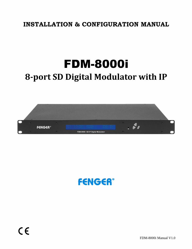
INSTALLATION & CONFIGURATION MANUAL
FDM-8000i
8-port SD Digital Modulator with IP

- 2 -
TABLE OF CONTENTS
SAFETY PRECAUTIONS ..................................................................................................................... 3
PACKAGE CONTENTS ........................................................................................................................ 4
PRODUCT DESCRIPTION ................................................................................................................... 4
SPECIFICATIONS ................................................................................................................................. 5
INSTALLATION .................................................................................................................................... 6
UNPACKING and INSPECTION ...................................................................................................... 6
PRODUCT PICTURES and DIAGRAMS......................................................................................... 6
HARDWARE INSTALLATION and CONNECTIONS .................................................................... 7
DEVICE Programming and Setup .......................................................................................................... 8
Connecting to the GUI Interface: ............................................................................................................ 8
Encoder Programming and Setup via GUI Interface: ............................................................................. 9
Overview Page of Fenger Encoder ..................................................................................................... 9
Common Setup ................................................................................................................................. 10
RF Setup ........................................................................................................................................... 11
Encoder Setup ................................................................................................................................... 12
IP Streaming Setup ........................................................................................................................... 13
Network Configuration ..................................................................................................................... 14
Administration .................................................................................................................................. 15
Front Panel LCD Encoder Menu Map .................................................................................................. 17
Modulator Configuration via Front Panel LCD .................................................................................... 18
Common Setup Menu ....................................................................................................................... 19
RF Setup Menu ................................................................................................................................ 19
Encoder Setup Menu ....................................................................................................................... 20
Web Management Network Setup .................................................................................................... 23
DIGITAL MODULATOR NOTES ....................................................................................................... 24

- 3 -
SAFETY PRECAUTIONS
The presence of this symbol is to alert the installer and user to the presence of uninsulated dangerous voltages within the product’s enclosure that may be of sufficient magnitude to produce a risk of electric shock.
TO REDUCE THE RISK OF FIRE OR ELECTRIC SHOCK, DO NOT EXPOSE THIS DEVICE TO RAIN OR MOISTURE. DO NOT OPEN THE UNIT. REFER SERVICING TO QUALIFIED PERSONNEL ONLY.
DO NOT apply power to the unit until all connections have been made, all components have been installed and all wiring has been properly terminated.
DO NOT terminate, change or uninstall any wiring without first disconnecting the unit’s power adapter from the device.
DO NOT connect the power supply to the device if the power cord is damaged.
DO NOT cut the power cord.
DO NOT plug the power cord into an AC outlet until all cables and connections to the device have been properly connected.
The device should be installed in an environment consistent with its operating temperature specifications. Placement next to heating devices and ducts is to be avoided as doing so may cause damage. The device should not be placed in areas of high humidity.
DO NOT cover any of the device’s ventilation openings.
DO NOT cover or obstruct the device’s fan or fan openings.
If the device has been in a cold environment allow it to warm to room temperature for at least 2 hours before connecting to an AC outlet.
- 4 -
PACKAGE CONTENTS
This package contains:
One FDM-8000i SD IP Digital Modulator
One Power Cord
One Installation Manual
Inspect the package before starting installation to ensure there is no damage and all supplied contents are present. Contact your distributor or dealer should the device be damaged or package contents are incomplete.
PRODUCT DESCRIPTION
FENGER’s FDM-8000i encoder/modulator converts Digital Video Broadcasting (DVB) standard definition video and audio signals to DVB-T. The unit features programmable channel and network names. Adjustable RF output (Normal, Inverted, and C.W.), adjustable logic channel numbering (LCN) and adjustable attenuation are standard features. The unit’s front-mounted LCD display and controls allow for easy configuration and adjustments.
The FDM-8000i SD IP Digital Modulator is perfect for multi-video distribution solutions in the commercial and institutional market (hotels, motels, sports bars, boats, restaurants, hospitals, casinos, business and university campus, etc.).
- 5 -
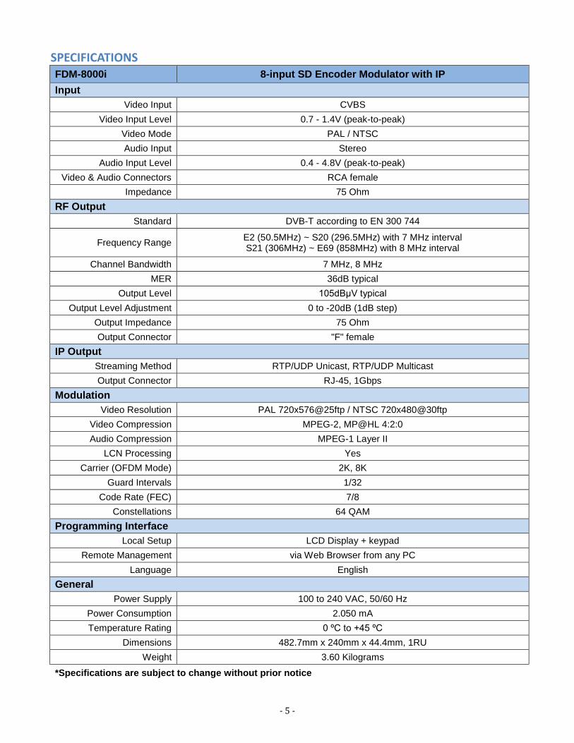
SPECIFICATIONS FDM-8000i 8-input SD Encoder Modulator with IP
Input
Video Input CVBS
Video Input Level 0.7 - 1.4V (peak-to-peak)
Video Mode PAL / NTSC
Audio Input Stereo
Audio Input Level 0.4 - 4.8V (peak-to-peak)
Video & Audio Connectors RCA female
Impedance 75 Ohm
RF Output
Standard DVB-T according to EN 300 744
Frequency Range E2 (50.5MHz) ~ S20 (296.5MHz) with 7 MHz interval S21 (306MHz) ~ E69 (858MHz) with 8 MHz interval
Channel Bandwidth 7 MHz, 8 MHz
MER 36dB typical
Output Level 105dBμV typical
Output Level Adjustment 0 to -20dB (1dB step)
Output Impedance 75 Ohm
Output Connector "F" female
IP Output
Streaming Method RTP/UDP Unicast, RTP/UDP Multicast
Output Connector RJ-45, 1Gbps
Modulation
Video Resolution PAL 720x576@25ftp / NTSC 720x480@30ftp
Video Compression MPEG-2, MP@HL 4:2:0
Audio Compression MPEG-1 Layer II
LCN Processing Yes
Carrier (OFDM Mode) 2K, 8K
Guard Intervals 1/32
Code Rate (FEC) 7/8
Constellations 64 QAM
Programming Interface
Local Setup LCD Display + keypad
Remote Management via Web Browser from any PC
Language English
General
Power Supply 100 to 240 VAC, 50/60 Hz
Power Consumption 2.050 mA
Temperature Rating 0 ºC to +45 ºC
Dimensions 482.7mm x 240mm x 44.4mm, 1RU
Weight 3.60 Kilograms
*Specifications are subject to change without prior notice
- 6 -
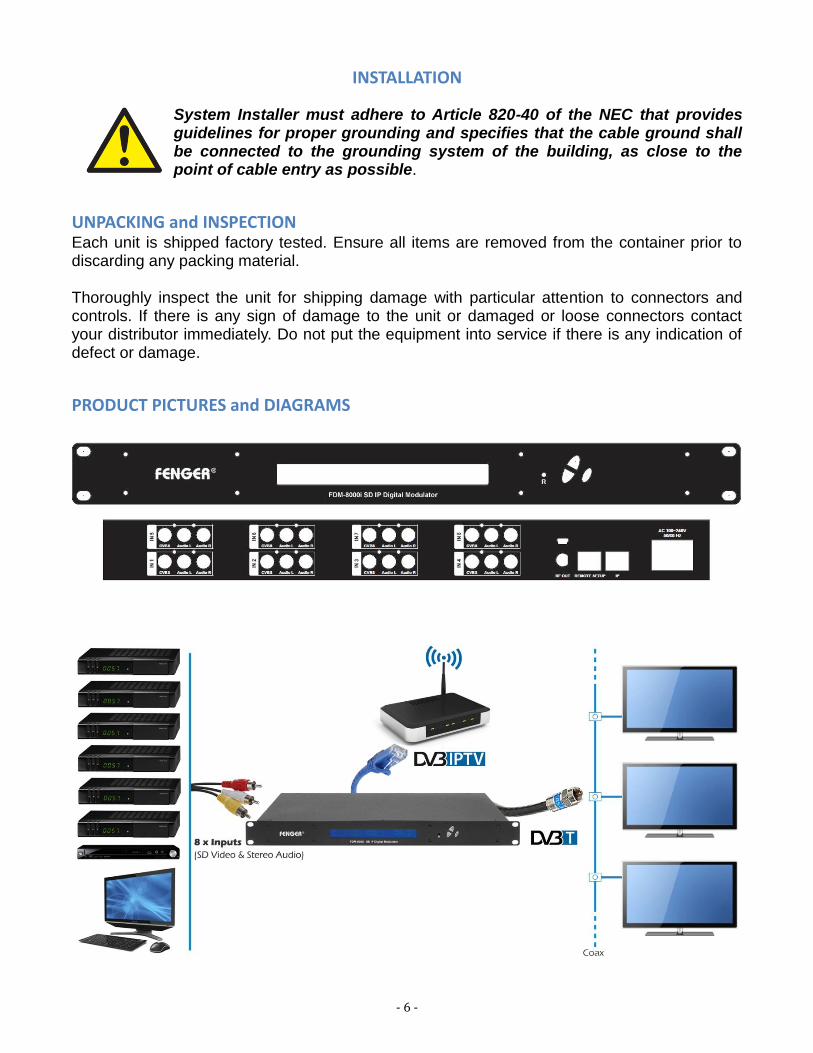
INSTALLATION
System Installer must adhere to Article 820-40 of the NEC that provides guidelines for proper grounding and specifies that the cable ground shall be connected to the grounding system of the building, as close to the point of cable entry as possible.
UNPACKING and INSPECTION Each unit is shipped factory tested. Ensure all items are removed from the container prior to discarding any packing material. Thoroughly inspect the unit for shipping damage with particular attention to connectors and controls. If there is any sign of damage to the unit or damaged or loose connectors contact your distributor immediately. Do not put the equipment into service if there is any indication of defect or damage.
PRODUCT PICTURES and DIAGRAMS

- 7 -
HARDWARE INSTALLATION and CONNECTIONS 1. The unit is designed to be rack mounted in a standard EIA 19” rack.
2. Use a 75Ω coaxial cable with RCA connectors to connect the video source (e.g., STB, DVD, VCR, Camera) to the unit’s yellow RCA VIDEO INPUT jack (IN1…IN8). Repeat this step for each video source connection. It is highly recommended that quality coaxial cable and connectors be used for all video source connections.
3. Use RCA cables to connect the audio source to the red / white AUDIO L and AUDIO R INPUT jacks (IN1…IN8). Use the red and white jacks for audio input or either one for a single input. Repeat this step for each audio source connection. Be sure the video and audio connections for each source are consistent with the unit’s inputs (IN1…IN8). It is highly recommended that quality cables and connectors be used for all audio source connections.
4. Use a quality 75Ω coaxial cable with “F” connectors from the unit’s RF OUT jack to the distribution system (combiner or reverse splitter).
5. Connect the included power cord to the unit’s POWER plug.
6. Connect the power cord to an appropriately rated AC power outlet.

- 8 -
DEVICE Programming and Setup To setup and program the Encoder you can use the GUI interface or the LCD Front Panel
Connecting to the GUI Interface: Connect an Ethernet cable directly (no Cross Over cable required) to the Web Management Port on the rear panel of the Encoder or connect the Ethernet cable to an Ethernet switch. Connect an Ethernet Cable to your PC.
Static IP address A static IP address must be used on the computer you use to configure the Encoder.
Refer to the computer’s operating software documentation for assistance on using static IP addresses.
Starting GUI Interface Open a web browser window Enter “http://192.168.1.9” in the web address field
Note: To setup the encoder using the Front Panel LCD see “Modulator Configuration via Front Panel LCD”.
- 9 -
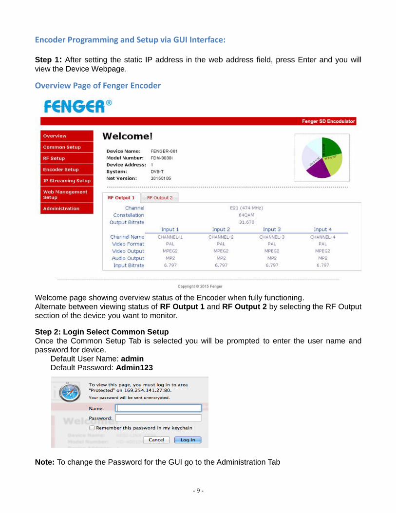
Encoder Programming and Setup via GUI Interface:
Step 1: After setting the static IP address in the web address field, press Enter and you will
view the Device Webpage.
Overview Page of Fenger Encoder
Welcome page showing overview status of the Encoder when fully functioning. Alternate between viewing status of RF Output 1 and RF Output 2 by selecting the RF Output section of the device you want to monitor. Step 2: Login Select Common Setup Once the Common Setup Tab is selected you will be prompted to enter the user name and password for device.
Default User Name: admin Default Password: Admin123
Note: To change the Password for the GUI go to the Administration Tab

- 10 -
Step 3: Common Setup Tab
Common Setup Use the Common Setup Page to set the Output channel, Attenuation, LCN Mode, and Device Address.
Step 4: Local Save Once all parameters are set you are required to do a Local Save. Notes on Changes: Changes made to an individual setup tab may require the installer to perform a Local Save AND Upload and Reboot to the device if only making changes to one parameter of the encoder. Example: Installer is required to change only the output channel for the device (No other changes to the device are required). Once the channel has been changed, the installer is required to perform 1: Local Save AND 2: Upload and Reboot. Notes on Channel Selection: The image shows the Output Channel is set to CH # E21. RF1 will output 1 COFDM signal carrying up to 4 digital audio/video channels (within your device's Bandwidth settings). The device will automatically set RF2 to Ch # E22.
- 11 -
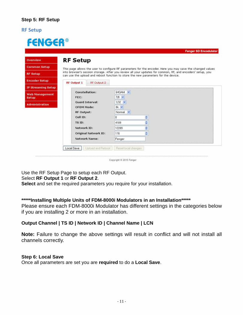
Step 5: RF Setup
RF Setup
Use the RF Setup Page to setup each RF Output. Select RF Output 1 or RF Output 2. Select and set the required parameters you require for your installation. *****Installing Multiple Units of FDM-8000i Modulators in an Installation*****
Please ensure each FDM-8000i Modulator has different settings in the categories below if you are installing 2 or more in an installation. Output Channel | TS ID | Network ID | Channel Name | LCN
Note: Failure to change the above settings will result in conflict and will not install all channels correctly. Step 6: Local Save Once all parameters are set you are required to do a Local Save.
- 12 -
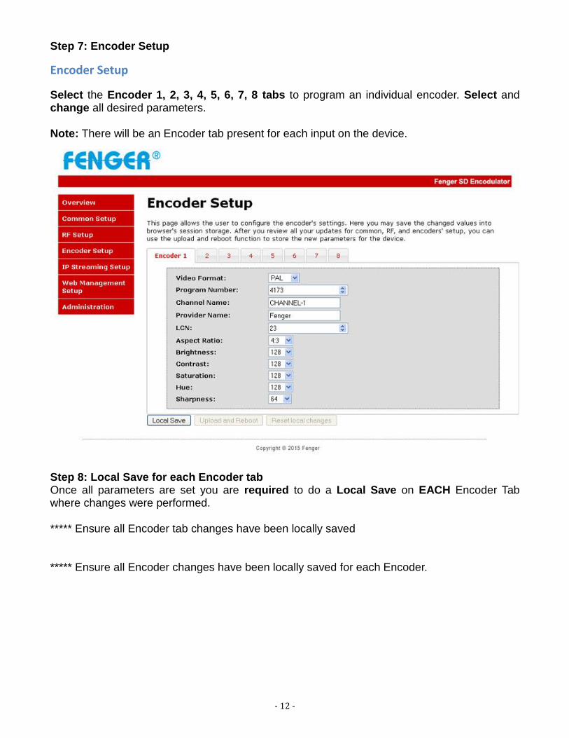
Step 7: Encoder Setup
Encoder Setup
Select the Encoder 1, 2, 3, 4, 5, 6, 7, 8 tabs to program an individual encoder. Select and change all desired parameters. Note: There will be an Encoder tab present for each input on the device.
Step 8: Local Save for each Encoder tab Once all parameters are set you are required to do a Local Save on EACH Encoder Tab where changes were performed. ***** Ensure all Encoder tab changes have been locally saved ***** Ensure all Encoder changes have been locally saved for each Encoder.

- 13 -
Step 9: IP Streaming
IP Streaming Setup
Select the Streaming 1, 2, 3, 4, 5, 6, 7, 8 tab to program an individual IP Streaming. Use the IP Streaming setup page to set your device's IP streaming IP Address, and select your streaming method protocol and Destination IP, Port, and TTL settings. Step 10: Local Save Once all parameters are set you are required to do a Local Save. ***** Ensure all Encoder changes have been locally saved before performing Step 11. Step 11: Upload and Reboot Once you have set all the encoder settings and performed a Local Save for each Setup tab. Select “Upload and Reboot” on the IP Streaming page after you have saved all your Local changes. This function will upload and save all parameters set in the Common, RF, Encoder, IP Streaming sections of the device. Your device will quickly reboot. Reminder: If changing only a setting on a specific setup page- remember to do a “Local Save” and “Upload and Reboot”.
We highly recommend you to save your encoder configuration files. See Administration tab for how to back up your settings.

- 14 -
Step 12: Network Configuration Tab
Network Configuration
Use the Network Setup Tab to configure the device’s IP address, Subnet Mask, Gateway, Enable/Disable DHCP, and set Host Name. Step 13: Save Network Configuration Save Config: Once all parameters are set you are required to select Save Config. This function will reboot and save the changes setting for the Network Configuration. Note: Only the Network Configuration changes will be saved.
- 15 -
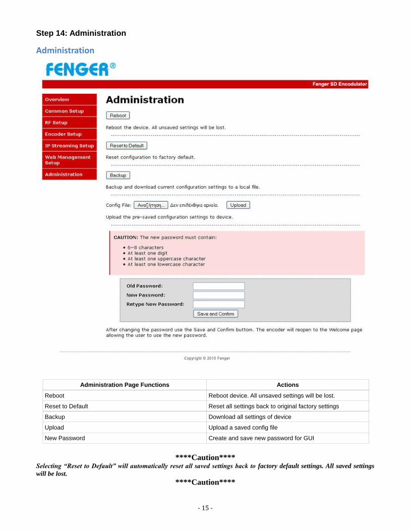
Step 14: Administration
Administration
Administration Page Functions Actions
Reboot Reboot device. All unsaved settings will be lost.
Reset to Default Reset all settings back to original factory settings
Backup Download all settings of device
Upload Upload a saved config file
New Password Create and save new password for GUI
****Caution****
Selecting “Reset to Default” will automatically reset all saved settings back to factory default settings. All saved settings
will be lost. ****Caution****
- 16 -
Step 15: If required, change GUI Password and Submit. Note: This password is for access to the GUI only. The LCD front Panel Password will not be changed and is set to prevent unauthorized users access to your device.
Saving your configuration files We highly recommend you to save your encoder configuration files. Simply Click the “Backup” button and the config files will be saved to your computer. To upload a configuration file- simply click “Choose File” then locate the file you want to upload. Click “Upload” to install the configuration files. This function is helpful to the installer when installing a large number of encoders in a single system.

- 17 -
Setup Using Front Panel LCD
Front Panel LCD Encoder Menu Map
Main Menu
Common
Setup
RF Setup Encoder
Setup
Exit IP Streaming
Setup
Output
Channel
Attenuation
LCN Mode
Device
Address
Default
Config
Back to Main
Select RF
Constellation
FEC
Guard
Interval
OFDM Mode
RF Output
Cell ID
TS ID
Network ID
Org Network
ID
Select
Encoder
Video
Format
Program
Num
Channel
Name
Provider
Name
LCN
Aspect Ratio
Video Output
HDCP
Audio Input
Audio
Output
Closed
Caption
Brightness
Contrast
Saturation
Network
Setup
Streaming
Setup
Back to Main
Back to Main
DHCP
Web Mngt
Setup
IP Address
Subnet Mask
Gateway
Network
Setup Menu
Streaming
Setup Menu
DHCP
IP Address
Subnet Mask
Gateway
Back to IP
Streaming
Select IP
Output
Enable
Streaming
Streaming
Method
Destination
IP
(IP Streaming Sub Menus)
Back to Main
Network
Name
Back to Main
Time to Live
Destination
Port
Back to IP
Streaming
Hue
- 18 -
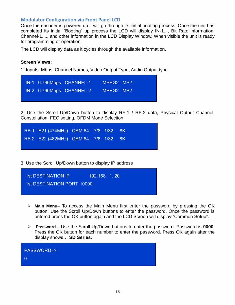
Modulator Configuration via Front Panel LCD Once the encoder is powered up it will go through its initial booting process. Once the unit has completed its initial “Booting” up process the LCD will display IN-1..., Bit Rate information, Channel-1...., and other information in the LCD Display Window. When visible the unit is ready for programming or operation.
The LCD will display data as it cycles through the available information.
Screen Views:
1: Inputs, Mbps, Channel Names, Video Output Type, Audio Output type
2: Use the Scroll Up/Down button to display RF-1 / RF-2 data, Physical Output Channel, Constellation, FEC setting, OFDM Mode Selection.
3: Use the Scroll Up/Down button to display IP address
Main Menu– To access the Main Menu first enter the password by pressing the OK button. Use the Scroll Up/Down buttons to enter the password. Once the password is entered press the OK button again and the LCD Screen will display “Common Setup”.
Password – Use the Scroll Up/Down buttons to enter the password. Password is 0000. Press the OK button for each number to enter the password. Press OK again after the display shows… SD Series.
IN-1 6.796Mbps CHANNEL-1 MPEG2 MP2
IN-2 6.796Mbps CHANNEL-2 MPEG2 MP2
RF-1 E21 (474MHz) QAM 64 7/8 1/32 8K
RF-2 E22 (482MHz) QAM 64 7/8 1/32 8K
1st DESTINATION IP 192.168. 1. 20
1st DESTINATION PORT 10000
PASSWORD=?
0

- 19 -
Common Setup MenuOutput Channel – Use the Scroll Up/Down button to change the output channel. Use the
Scroll Up/Down buttons to select the desired output channel. Once the desired output
channel is selected press the OK button to set the channel.
The LCD Display will show both the channel number and the frequency number of the
output channel (example: E21 474MHz)
Note: The RF2 Channel Physical output is determined by the selection of output channel of RF1
The Encoder prevents you from selecting the last channel in the device. **See Notes on
Channel Selection for more information on this topic
Attenuation – Use the Scroll Up/Down button to select Attenuation. Press the OK button
to enter the Attenuation menu. Use the Scroll/Up down button to select the desired
attenuation in 1dB increments from 0 to minus 20 dB. Once the desired attenuation level
is found press the OK button to set.
LCN – Use the Scroll Up/Down button to select LCN MODE. Press the OK button to
enter the LCN menu. Menu options are APN, NORDIG, ITC, EACEM, AU, and, NZ.
Factory default: ITC. Use the Scroll Up/Down button to select the desired LCN and press
the OK button to set.
Device Address – Use the Scroll Up/Down button to select Device Address. Press the
OK button to enter the Device Address menu. Use the Scroll Up/Down to select the
Desired Address ranging from 1 to 255 then press OK to set. A unique device address is
required if setting up more than 1 encoder per site. This allows the user to distinguish
each device.
Default Configuration –To reset the Encoder/Modulator back to the factory default
select the Default Configuration Menu. Press OK to enter the Default Configuration
Menu. Using the Up/Down button select YES to reset all programmed settings back to
the factory default setting. Factory Default: NO.
Caution: Once the “YES” button is pressed the unit will automatically reset to the factory default
settings. All settings or changes to the encoder/modulator will be lost.
Back to Main- Select Back to Main to escape the Common Setup Menu.
RF Setup Menu
Select RF- Press the OK button to enter the Select RF menu. Use the Scroll Up/Down
button to Select the RF section of the Encoder. Select 1 or Select 2.
Constellation – Use the Scroll Up/Down button to select Constellation. Press the OK
button to enter the Constellation menu. The unit is default to QAM64. Press the OK
button to set.
FEC- Use the Scroll Up/Down button to select the FEC menu. The unit is default to 7/8.
Press the OK button to set.
GUARD INTERVAL – Use the Scroll Up/Down button to select Guard Interval. Press
the OK button to enter the Guard Interval menu. The unit is default to 7/8. Press the OK
button to set.

- 20 -
OFDM - Use the Scroll Up/Down button to select the OFDM menu. Press the OK button
to enter the OFDM menu. Use the Scroll Up/Down to select the OFDM 2K or 8K. Press
OK to set.
RF Output – Use the Scroll Up/Down button to select RF Output. Press the OK button to
enter the RF Output menu. Menu options are Normal, Inverted and C.W. The factory
default is Normal. Use the Scroll Up/Down button to select the desired RF Output and
press the OK button to set.
CELL ID – Use the Scroll Up/Down button to select CELL ID. Press the OK button to
enter the CELL ID menu. Use the Scroll Up/Down button to select the desired CELL ID
ranging from 0 to 65535 then press the OK button to set. Factory default is 0.
TS ID – Use the Scroll Up/Down button to select TS ID. Press the OK button to enter the
TS ID menu. Use the Scroll Up/Down button to select the desired Stream ID ranging
from 0 to 65535 then press the OK button to set.
Network ID – Use the Scroll Up/Down button to select Network ID. Press the OK button
to enter the Network ID menu. Use the Scroll Up/Down button to select the desired
Network ID ranging from 0 to 65535 then press the OK button to set.
ORG Network ID – Use the Scroll Up/Down button to select ORG Network ID. Press
the OK button to enter the ORG Network ID menu. Use the Scroll Up/Down button to
select the desired ID ranging from 0 to 65535 then press the OK button to set.
Network Name – Use the Scroll Up/Down button to select Network Name. Press the OK
button to enter the Network Name menu. Use the Scroll Up/Down button to select the
first character for the desired Network Name then press the OK button to set. Repeat the
process for each character in the desired Network Name. A Network Name can consist up
to 16 characters.
Back to Main- Select Back to Main to escape the RF Setup Menu.
Encoder Setup Menu Select Encoder – Press the OK button to enter the Select Encoder menu. Use the Scroll
Up/Down button to Select the section of the Encoder. Select 1 to 8 encoder.
Video Format – Use the Scroll Up/Down button to select Video Format. Press the OK button to enter the Video Format menu. Use the Scroll Up/Down button to select the Video Format option: PAL, NTSC. Factory default: PAL. Press the OK button to set.
Program Num - Use the Scroll Up/Down button to set 1 Program Num (Number).
Press the OK button to enter the Program Num menu. Use the Scroll Up/Down to select
the Program Num ranging from 1 to 65535 then press OK to set.
Channel Name – Use the Scroll Up/Down button to select Channel Name. Press the OK
button to enter the Channel Name menu. Use the Scroll Up/Down menu to select the first
character of the desired Channel Name then press the OK button to set. Repeat the
process until the Channel Name is completed.
The Channel Name can be 7 characters long. Factory Default: CHANNEL-1,
CHANNEL-2, to CHANNEL-8.

- 21 -
PROVIDER NAME – Use the Scroll Up/Down button to select Provider Name. Press
the OK button to enter the Provider Name menu. Use the Scroll Up/Down menu to select
the first character of the desired Provider Name then press the OK button to set. Repeat
the process until the Provider Name is completed. The Provider Name can be 16
characters long.
LCN-Use the Scroll Up/Down button to set LCN. Press the OK button to enter The
Source ID menu. Use the Scroll Up/Down to set the Source ID. Range: 1 to 999. Press
OK to set.
Aspect Ratio – Use the Scroll Up/Down button to select Aspect Ratio. Press the OK
button to enter the Aspect Ratio menu. Use the Scroll Up/Down button to select the
desired Aspect Ratio option of 4:3 or 16:9 then press the OK button to set. Factory
default: 4:3.
Brightness – Use the Scroll Up/Down button to select Brightness. Press the OK button to
enter the Brightness menu. Use the Scroll Up/Down button to select the desired
Brightness value (0 to 255) and press the OK button to set. Factory default: 128.
Contrast – Use the Scroll Up/Down button to select Contrast. Press the OK button to
enter the Contrast menu. Use the Scroll Up/Down button to select the desired Contrast
value (0 to 255) and press the OK button to set. Factory default: 128.
Saturation – Use the Scroll Up/Down button to select Saturation. Press the OK button to
enter the Saturation menu. Use the Scroll Up/Down button to select the desired Saturation
value (0 to 255) and press the OK button to set. Factory default: 128.
Hue – Use the Scroll Up/Down button to select Hue. Press the OK button to enter the
Hue menu. Use the Scroll Up/Down button to select the desired Hue value (0 to 255) and
press the OK button to set. Factory default: 128.
Sharpness – Use the Scroll Up/Down button to select Sharpness. Press the OK button to
enter the Sharpness menu. Use the Scroll Up/Down button to select the desired Sharpness
value (0 to 127) and press the OK button to set. Factory default: 64.
Back to Main- Select Back to Main to escape the Encoder Setup Menu.
IP Streaming Setup
Network Setup
DHCP – Use the Scroll Up/Down button to select DHCP. Press the OK button to enter
the DHCP menu. Use the Scroll Up/Down button to Enable/Disable. Press the OK button
to set.
IP Address – Use the Scroll Up/Down button to select IP Address. Press the OK button
to enter the IP Address menu. Use the Scroll Up/Down button to enter the IP Address.
Use the Scroll Up/Down menu to select the desired IP Address then press the OK button
to set. Repeat the process until the IP Address is completed. Press the OK button to set.
Note: If DHCP is enabled you will not be able to set an IP address. Select DHCP disabled
if Static IP Address required.

- 22 -
Subnet Mask – Use the Scroll Up/Down button to select Subnet Mask. Press the OK
button to enter the Subnet Mask menu. Use the Scroll Up/Down button to enter the
Subnet Mask. Use the Scroll Up/Down menu to select the first number of the desired
Subnet Mask then press the OK button to set. Repeat the process until the Subnet Mask is
completed. Press the OK button to set.
Gateway – Use the Scroll Up/Down button to select Gateway Address. Press the OK
button to enter the Gateway Address menu. Use the Scroll Up/Down button to enter the
Gateway Address. Use the Scroll Up/Down menu to select the first number of the desired
Gateway Address then press the OK button to set. Repeat the process until the Gateway
Address is completed. Press the OK button to set.
Back to IP Streaming Setup- Select Back to Main to escape the Web Management
Network Setup Menu.
Streaming Setup
Select IP Output – Use the Scroll Up/Down button to enter the IP Output seletion. Select
IP output port 1 to 8 to set.
Enable IP Streaming – Use the Scroll Up/Down button to enter Enable IP Streaming
selection. Press OK button to select ENABLE/DISABLE the IP Streaming.
Streaming Method – Use the Scroll Up/Down button to select Streaming Method. Press
the OK button to enter the Streaming Method menu. Use the Scroll Up/Down button to
select the Streaming Method required. Select: RTP UNICAST, UDP UNICAST, RPT
MULTICAST, or UDP MULTICAST. Press the OK button to set.
1st Destination IP – Use the Scroll Up/Down button to select 1
st Destination IP
(Address). Press the OK button to enter the 1st Destination IP Address menu. Use the
Scroll Up/Down button to set the Destination IP Address. Note: By selecting Unicast in
the Streaming Method Menu the default address begins at 192.168.1.20. Use the Scroll
Up/Down button to set the Destination IP Address. Press the OK button to set. Multicast
begins at 224.1.1.1. Press the OK button to set.
Destination IP Address Range(s):
Unicast: 0.0.0.0 ~ 223.255.255.255
Multicast: 224.0.0.0 ~ 239.255.255.255
1st Destination Port Number – Use the Scroll Up/Down button to select DES Port
Number (Destination Port Number). Press the OK button to enter the 1st Destination Port
Number menu. Use the Scroll Up/Down button to set. Press the OK button to set.
For 2 IP Version Only ( 2nd
Destination IP / 2nd
Destination Port) Functions
2nd
Destination IP – Use the Scroll Up/Down button to select 2nd
Destination IP
(Address). Press the OK button to enter the 2nd
Destination IP Address menu. Use the
Scroll Up/Down button to set the Destination IP Address. Note: By selecting Unicast in
the Streaming Method Menu the default address begins at 192.168.1.21. Use the Scroll
Up/Down button to set the Destination IP Address. Press the OK button to set. Multicast
begins at 224.1.1.2. Press the OK button to set.
- 23 -
Time To Live – Use the Scroll Up/Down button to select Time To Live menu. Press the
OK button to enter the Time To Live .menu. Use the Scroll Up/Down button to select
TTL. Press the OK button to set. Default Settings: Unicast: 63. Multicast: 4. TTL Range:
1~ 255.
Back to IP Streaming Setup- Select Back to Main to escape the Streaming – IP
Streaming Sub Menu.
Web Management Network Setup DHCP – Use the Scroll Up/Down button to select DHCP. Press the OK button to enter
the DHCP menu. Use the Scroll Up/Down button to Enable/Disable. Press the OK button
to set.
IP Address – Use the Scroll Up/Down button to select IP Address. Press the OK button
to enter the IP Address menu. Use the Scroll Up/Down button to enter the IP Address.
Use the Scroll Up/Down menu to select the desired IP Address then press the OK button
to set. Repeat the process until the IP Address is completed. Press the OK button to set.
Note: If DHCP is enabled you will not be able to set an IP address. Select DHCP disabled
if Static IP Address required.
Subnet Mask – Use the Scroll Up/Down button to select Subnet Mask. Press the OK
button to enter the Subnet Mask menu. Use the Scroll Up/Down button to enter the
Subnet Mask. Use the Scroll Up/Down menu to select the first number of the desired
Subnet Mask then press the OK button to set. Repeat the process until the Subnet Mask is
completed. Press the OK button to set.
Gateway Address – Use the Scroll Up/Down button to select Gateway Address. Press
the OK button to enter the Gateway Address menu. Use the Scroll Up/Down button to
enter the Gateway Address. Use the Scroll Up/Down menu to select the first number of
the desired Gateway Address then press the OK button to set. Repeat the process until the
Gateway Address is completed. Press the OK button to set.
Back to Main - Select Back to Main to escape the Web Management Net Setup Menu.

- 24 -
DIGITAL MODULATOR NOTES
PRODUCT NOTES:
ITEM
VALUE
PASSWORD
SERIAL NUMBER
INSTALLATION DATE
PURCHASE DATE
VIDEO 1 INPUT
VIDEO 2 INPUT
VIDEO 3 INPUT
VIDEO 4 INPUT
VIDEO 5 INPUT
VIDEO 6 INPUT
VIDEO 7 INPUT
VIDEO 8 INPUT
************************************************************************************
DECLARATION OF CONFORMITY Hereby, KOSMOSAT SA confirms that the product FDM-8000i (SD Digital Modulator with IP) conforms to relevant EEC harmonized standards and consequently can carry CE-mark. Relevant harmonized standards: EN 55013:2001+A1:2003+A2:2006 Class B EN 55020:2007+A11:2011 EN 60065:2002
Copy of the Declaration of Conformity you may ask from the company’s offices in the address: 1 Nireos Str., Paleo Faliro, Attica 17561, or after request in the e-mail address: [email protected]