
Types of microscope Electron Microscope An electron microscope.
Microscope Components:
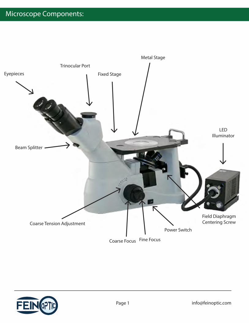
Trinocular Port
Fixed StageEyepieces
Metal Stage
Field DiaphragmCentering Screw
Power Switch
Fine FocusCoarse Focus
Coarse Tension Adjustment
Beam Splitter
LEDIlluminator
Microscope Components:
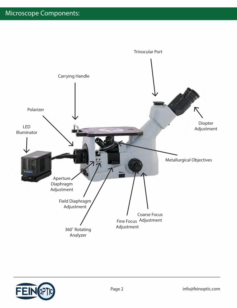
Carrying Handle
Polarizer
360˚ RotatingAnalyzer
Trinocular Port
DiopterAdjustment
Metallurgical Objectives
ApertureDiaphragmAdjustment
Field DiaphragmAdjustment
Fine Focus Adjustment
Coarse Focus Adjustment
LEDIlluminator
Before Use:
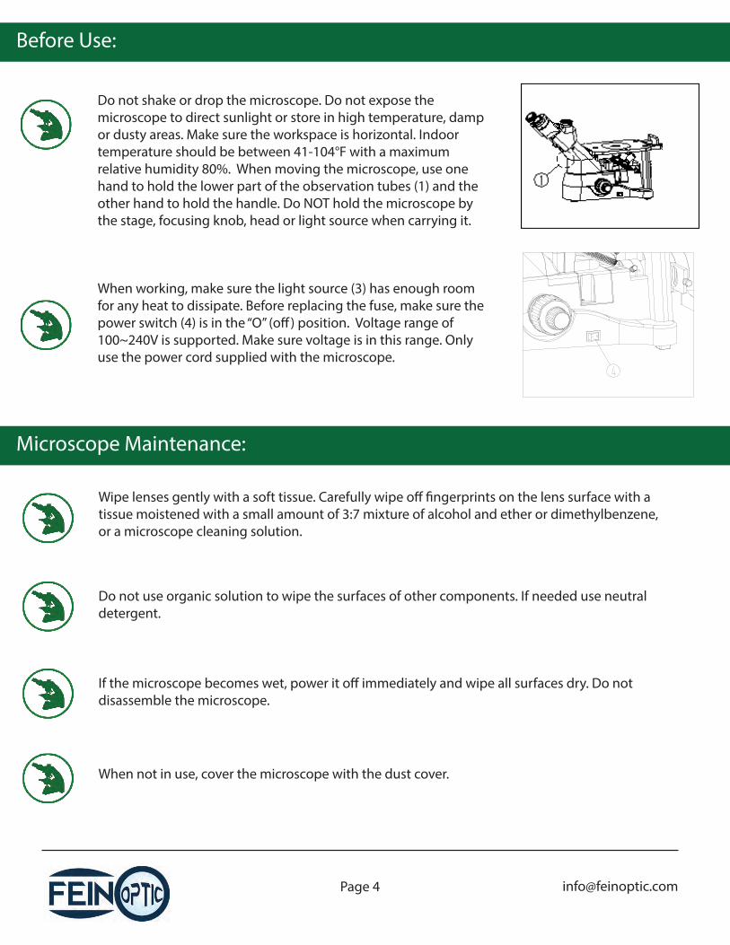
Do not shake or drop the microscope. Do not expose the microscope to direct sunlight or store in high temperature, damp or dusty areas. Make sure the workspace is horizontal. Indoor temperature should be between 41-104°F with a maximum relative humidity 80%. When moving the microscope, use one hand to hold the lower part of the observation tubes (1) and the other hand to hold the handle. Do NOT hold the microscope by the stage, focusing knob, head or light source when carrying it.
When working, make sure the light source (3) has enough room for any heat to dissipate. Before replacing the fuse, make sure the power switch (4) is in the “O” (o�) position. Voltage range of 100~240V is supported. Make sure voltage is in this range. Only use the power cord supplied with the microscope.
Microscope Maintenance:
Wipe lenses gently with a soft tissue. Carefully wipe o� �ngerprints on the lens surface with a tissue moistened with a small amount of 3:7 mixture of alcohol and ether or dimethylbenzene, or a microscope cleaning solution.
Do not use organic solution to wipe the surfaces of other components. If needed use neutral detergent.
If the microscope becomes wet, power it o� immediately and wipe all surfaces dry. Do not disassemble the microscope.
When not in use, cover the microscope with the dust cover.
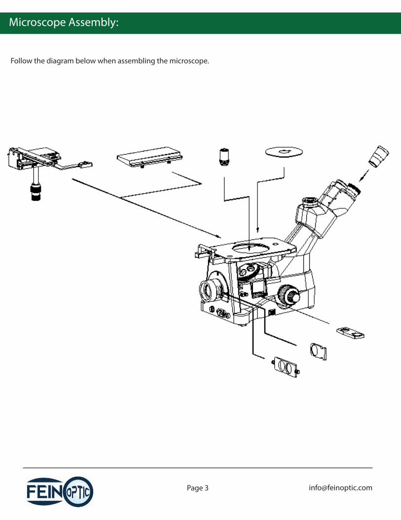
Microscope Assembly:
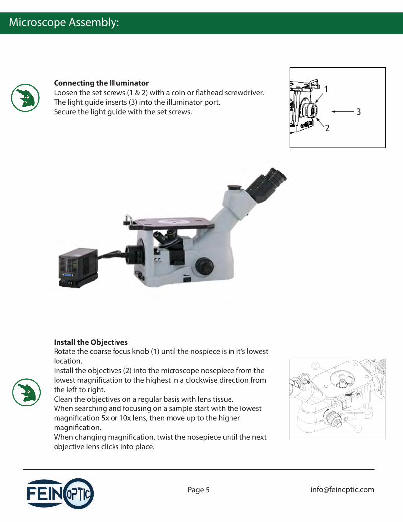
Connecting the IlluminatorLoosen the set screws (1 & 2) with a coin or �athead screwdriver. The light guide inserts (3) into the illuminator port.Secure the light guide with the set screws.
Install the ObjectivesRotate the coarse focus knob (1) until the nospiece is in it’s lowest location.Install the objectives (2) into the microscope nosepiece from the lowest magni�cation to the highest in a clockwise direction from the left to right.Clean the objectives on a regular basis with lens tissue.When searching and focusing on a sample start with the lowest magni�cation 5x or 10x lens, then move up to the higher magni�cation.When changing magni�cation, twist the nosepiece until the next objective lens clicks into place.
Microscope Assembly:
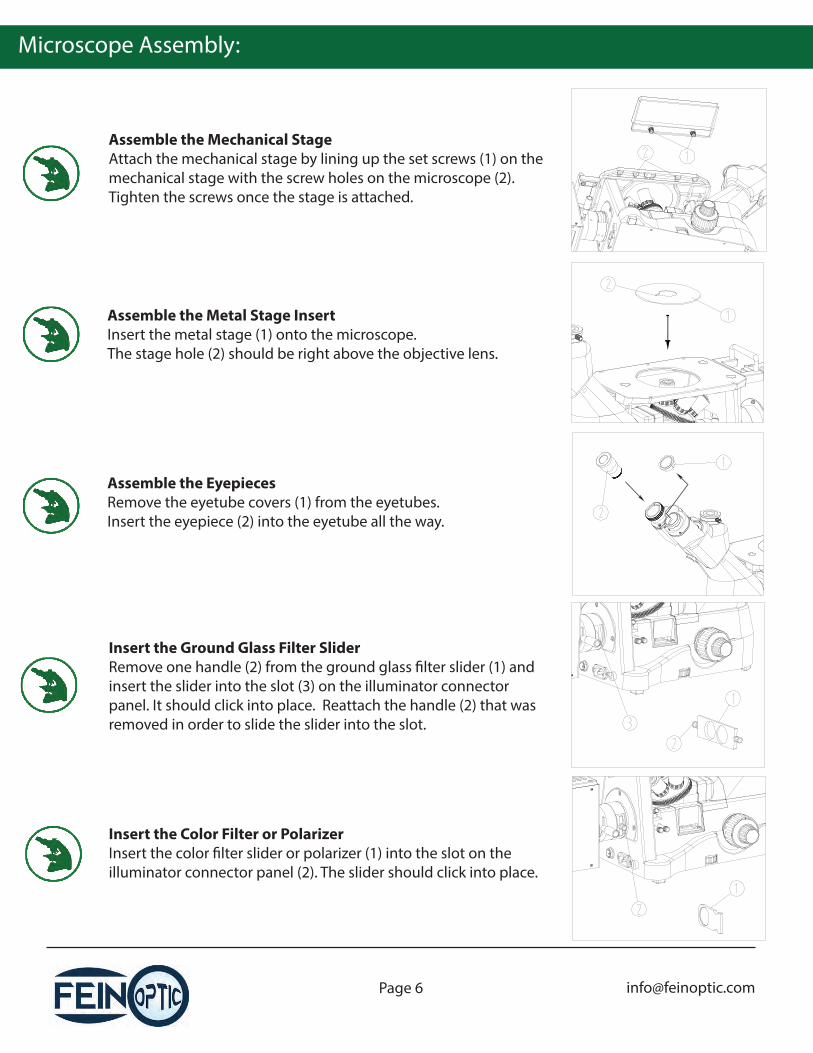
Assemble the Mechanical StageAttach the mechanical stage by lining up the set screws (1) on the mechanical stage with the screw holes on the microscope (2). Tighten the screws once the stage is attached.
Insert the Ground Glass Filter SliderRemove one handle (2) from the ground glass �lter slider (1) and insert the slider into the slot (3) on the illuminator connector panel. It should click into place. Reattach the handle (2) that was removed in order to slide the slider into the slot.
Assemble the Metal Stage InsertInsert the metal stage (1) onto the microscope.The stage hole (2) should be right above the objective lens.
Assemble the EyepiecesRemove the eyetube covers (1) from the eyetubes.Insert the eyepiece (2) into the eyetube all the way.
Insert the Color Filter or PolarizerInsert the color �lter slider or polarizer (1) into the slot on the illuminator connector panel (2). The slider should click into place.
Microscope Assembly:
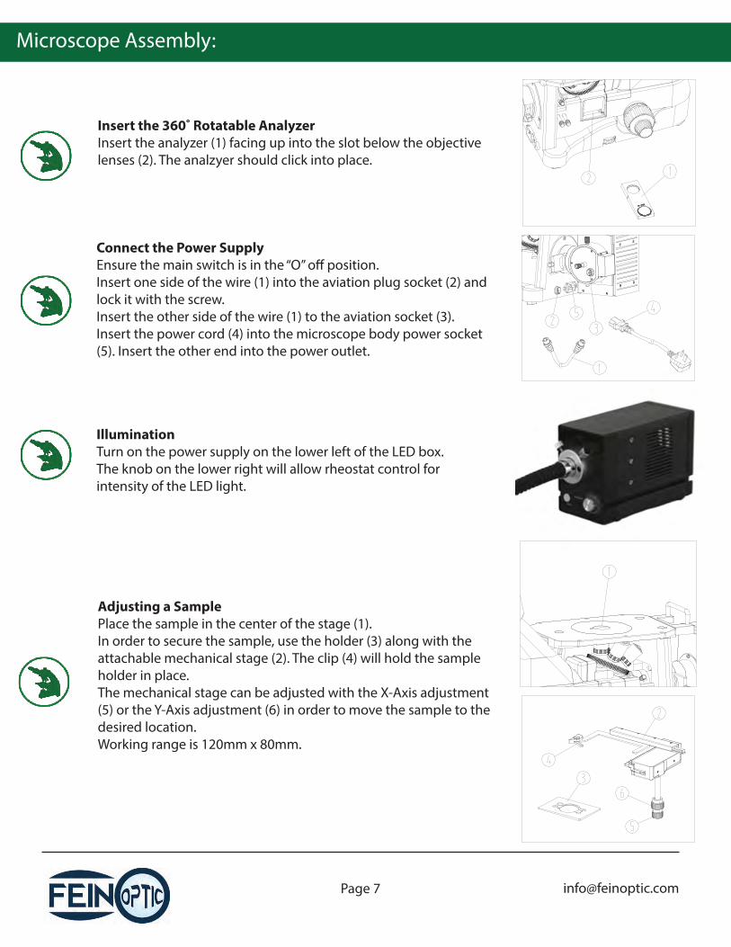
Insert the 360˚ Rotatable AnalyzerInsert the analyzer (1) facing up into the slot below the objective lenses (2). The analzyer should click into place.
Adjusting a SamplePlace the sample in the center of the stage (1).In order to secure the sample, use the holder (3) along with the attachable mechanical stage (2). The clip (4) will hold the sample holder in place.The mechanical stage can be adjusted with the X-Axis adjustment (5) or the Y-Axis adjustment (6) in order to move the sample to the desired location.Working range is 120mm x 80mm.
Connect the Power SupplyEnsure the main switch is in the “O” o� position.Insert one side of the wire (1) into the aviation plug socket (2) and lock it with the screw.Insert the other side of the wire (1) to the aviation socket (3).Insert the power cord (4) into the microscope body power socket (5). Insert the other end into the power outlet.
IlluminationTurn on the power supply on the lower left of the LED box.The knob on the lower right will allow rheostat control for intensity of the LED light.
Microscope Operation:
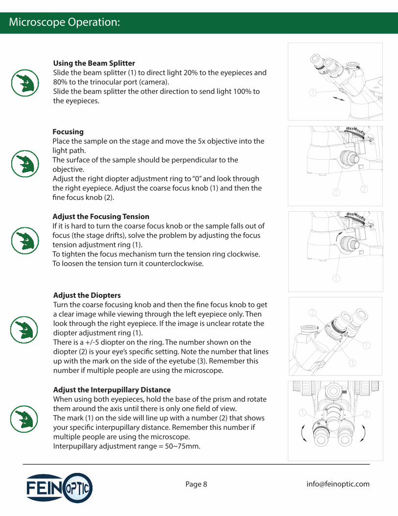
Using the Beam SplitterSlide the beam splitter (1) to direct light 20% to the eyepieces and 80% to the trinocular port (camera).Slide the beam splitter the other direction to send light 100% to the eyepieces.
Adjust the DioptersTurn the coarse focusing knob and then the �ne focus knob to get a clear image while viewing through the left eyepiece only. Then look through the right eyepiece. If the image is unclear rotate the diopter adjustment ring (1).There is a +/-5 diopter on the ring. The number shown on the diopter (2) is your eye’s speci�c setting. Note the number that lines up with the mark on the side of the eyetube (3). Remember this number if multiple people are using the microscope.
FocusingPlace the sample on the stage and move the 5x objective into the light path.The surface of the sample should be perpendicular to the objective.Adjust the right diopter adjustment ring to “0” and look through the right eyepiece. Adjust the coarse focus knob (1) and then the �ne focus knob (2).
Adjust the Focusing TensionIf it is hard to turn the coarse focus knob or the sample falls out of focus (the stage drifts), solve the problem by adjusting the focus tension adjustment ring (1).To tighten the focus mechanism turn the tension ring clockwise. To loosen the tension turn it counterclockwise.
Adjust the Interpupillary DistanceWhen using both eyepieces, hold the base of the prism and rotate them around the axis until there is only one �eld of view.The mark (1) on the side will line up with a number (2) that shows your speci�c interpupillary distance. Remember this number if multiple people are using the microscope.Interpupillary adjustment range = 50~75mm.
Microscope Operation:
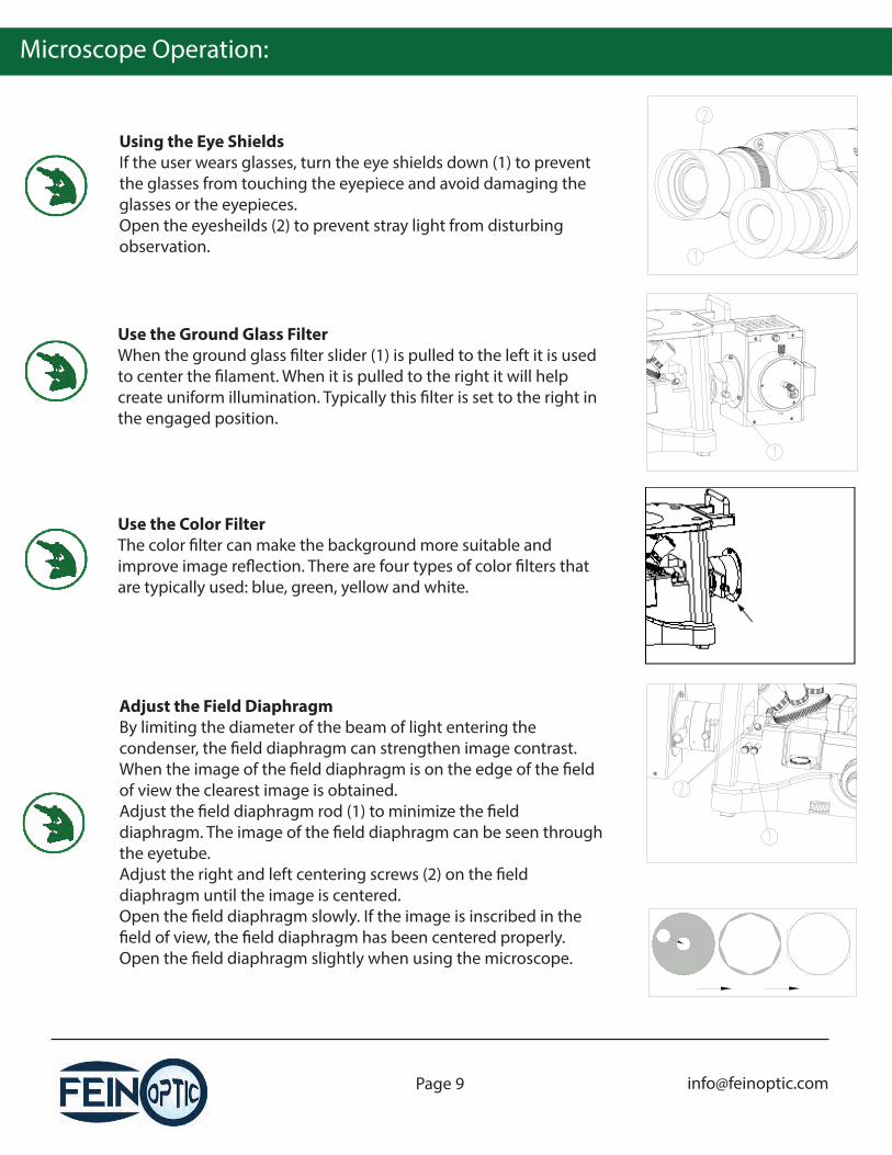
Using the Eye ShieldsIf the user wears glasses, turn the eye shields down (1) to prevent the glasses from touching the eyepiece and avoid damaging the glasses or the eyepieces.Open the eyesheilds (2) to prevent stray light from disturbing observation.
Adjust the Field DiaphragmBy limiting the diameter of the beam of light entering the condenser, the �eld diaphragm can strengthen image contrast. When the image of the �eld diaphragm is on the edge of the �eld of view the clearest image is obtained.Adjust the �eld diaphragm rod (1) to minimize the �eld diaphragm. The image of the �eld diaphragm can be seen through the eyetube.Adjust the right and left centering screws (2) on the �eld diaphragm until the image is centered.Open the �eld diaphragm slowly. If the image is inscribed in the �eld of view, the �eld diaphragm has been centered properly.Open the �eld diaphragm slightly when using the microscope.
Use the Ground Glass FilterWhen the ground glass �lter slider (1) is pulled to the left it is used to center the �lament. When it is pulled to the right it will help create uniform illumination. Typically this �lter is set to the right in the engaged position.
Use the Color FilterThe color �lter can make the background more suitable and improve image re�ection. There are four types of color �lters that are typically used: blue, green, yellow and white.

Microscope Operation:
Adjust the Aperture DiaphragmThe aperture diaphragm decides the numerical aperture (NA) of the illumination. If the NA of the illumination matches the NA of the objective, the best resolution is obtained with increased contrast and depth of �eld.Adjusting the aperture diaphragm is the same as adjusting the �eld diaphragm.Adjust the size of the aperture diaphragm for comfortable viewing.
Using the Simple Polarizing KitsThe simple polarizing kit includes the polarizer (1) and the 360˚ rotating analyzer (2).When using the polarizer remove the color �lter from the light path.Dialing the turntable on the 360˚ rotating analyzer can change the orthogonal states of the polarized light.When the turntable on the analyzer is set to “0” the analyzer and polarizer are in the orthogonal state.
Microscope C-Mount & Objectives:
LWD Plan Achromat
Semi APO Bright�eld
Objective Type Part # / Magni�cation Numerical Aperture Working Distance
FMPLN5 / 5xFMPLN10 / 10x FMPLN20 / 20xFMPLN50 / 50x
0.150.300.450.55
10.8mm12.2mm
4mm7.9mm
BF-SAPO-M20 / 20x 0.500.800.90
3.2mm1.2mm
1mm
BF-SAPO-M5 / 5x 0.15 19.5mmBF-SAPO-M10 / 10x 0.30 10.9mm
BF-SAPO-M50 / 50xBF-SAPO-M100 / 100x
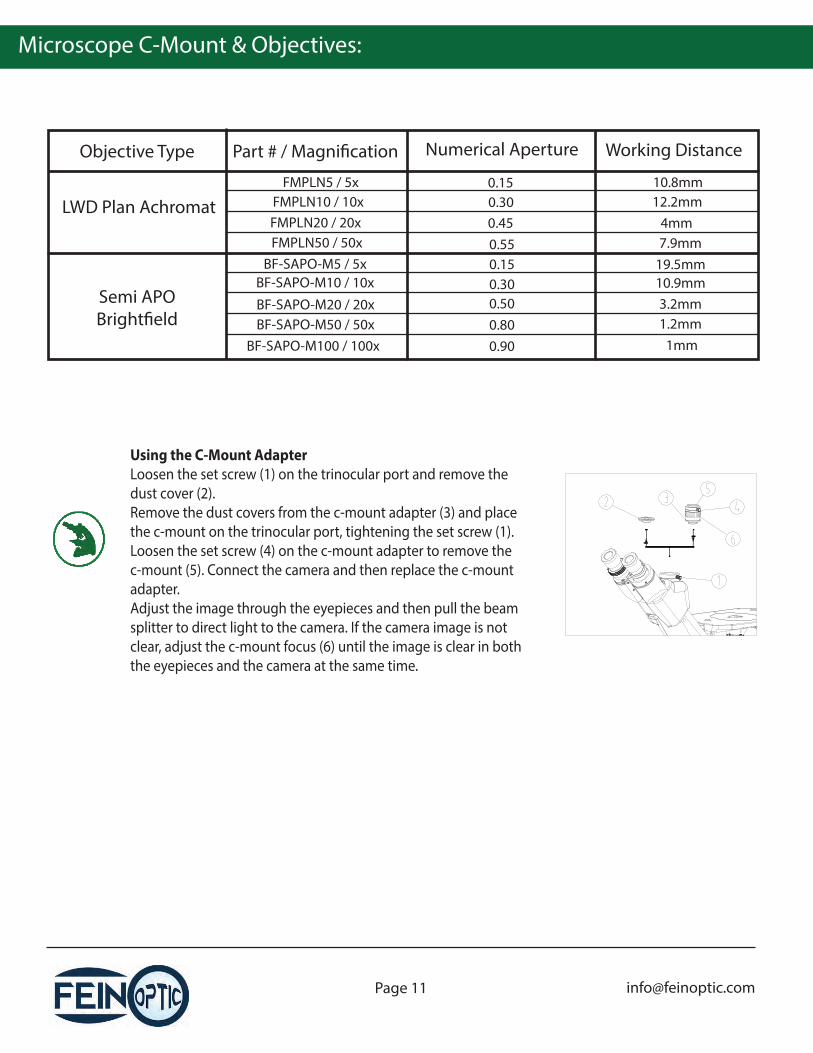
Using the C-Mount AdapterLoosen the set screw (1) on the trinocular port and remove the dust cover (2).Remove the dust covers from the c-mount adapter (3) and place the c-mount on the trinocular port, tightening the set screw (1).Loosen the set screw (4) on the c-mount adapter to remove the c-mount (5). Connect the camera and then replace the c-mount adapter.Adjust the image through the eyepieces and then pull the beam splitter to direct light to the camera. If the camera image is not clear, adjust the c-mount focus (6) until the image is clear in both the eyepieces and the camera at the same time.

Troubleshooting:
Optical Troubleshooting
Problem Cause Solution
Light is bright, but �eld of view is dark.
Field diaphragm is not large enough.
Rheostat on light is turned down.
Polarizer or analyzer blocking light.
Open the �eld diaphragm.
Adjust the rheostat.
Remove polarizer/analyzer.
Side of the �eld of view is dark or uneven.
Nosepiece is not clicked into position.Stain or dust has accumulated on the condenser, objective, eyepieces or light source.
Rotate nosepiece into place.Clean surfaces of condenser, objectives, eyepieces and light source.
Dust is observed in the �eld of view.
Dust has accumulated on the specimen.
Dust is on the objective or eyepiece.
Clean the sample.
Clean the objective and eyepieces.
Image is not clear.
A cover slip is being used. Remove cover slip.
The sample is not vertical to the objective. Adjust sample.
Aperture diaphragm not open.
Clean eyepiece / objective.
Beam splitter is not in correct position. Adjust beam splitter.
One side of �eld of view is dark or the image moves
while focusing.
Specimen is not �xed. Adjust sample on stage.
Nosepiece is not clicked into position. Click nosepiece into place.
Eyes fatigue quickly during use or the right
�eld of view doesn’t match with the left.
Interpupillary distance is not set properly. Adjust interpupillary distance.
Diopter adjustment is not set properly. Adjust the diopters.
Di�erent eyepieces are being used in the left and right eyetube.
Use the same eyepieces in each eyetube. Use the Fein Optic FPL-WF10x, FN22 Eyepieces.
Beam splitter is pulled out. Push the beam splitter in.
The �lter, polarizer or analyzer is not in position.
Remove / reinsert �lters and sliders.
Beam splitter is not in correct position. Adjust the beam splitter.
Adjust aperture diaphragm.
Stain or dust is on the lens.

Troubleshooting:
Mechanical & Electrical Troubleshooting
Problem Cause Solution
Stage drifts or falls. Tension knob is too loose. Tighten tension knob slightly.
Coarse focusing knob is too tight.
Tension knob is too tight. Loosen tension knob slightly.
Mechanical Troubleshooting: