Feed Mill Design - satradehub.org · construction must be compatible. ... Design capacity = 75 MTPH...
49
Feed Mill Design By Fred J. Fairchild, P. E. Department of Grain Science and Industry Kansas State University
Transcript of Feed Mill Design - satradehub.org · construction must be compatible. ... Design capacity = 75 MTPH...

Feed Mill Design
By
Fred J. Fairchild, P. E.
Department of Grain Science and
Industry
Kansas State University


Determine Needs
Determine Purpose
Design to
Requirements
Planning
Product Mix
Bulk Feeds
Mash
Pellets & Crumbles
Textured Feeds
Miscellaneous

Product Mix
Bagged Feeds
Mash
Pellets & Crumbles
Textured Feeds
Whole/Processed Grains
Premixes
Scratch Feed
Product Mix
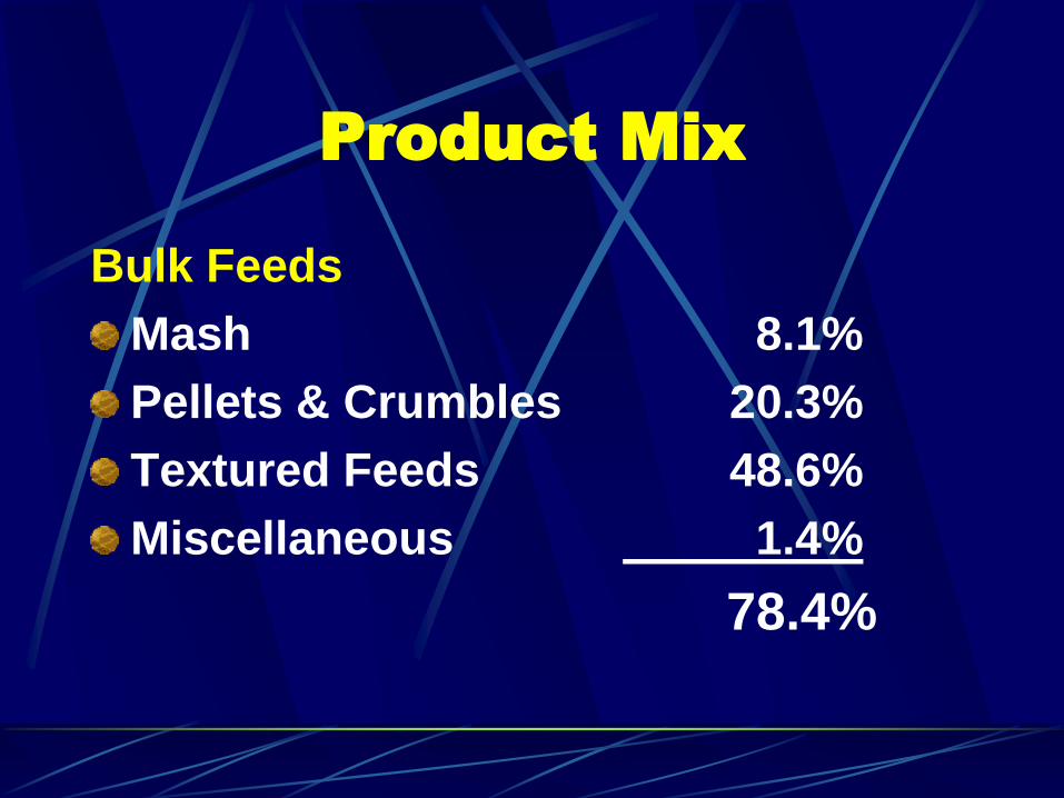
Bulk Feeds
Mash 8.1%
Pellets & Crumbles 20.3%
Textured Feeds 48.6%
Miscellaneous 1.4%
78.4%

Product Mix
Bagged Feeds
Mash 1.4%
Pellets & Crumbles 5.4%
Textured Feeds 8.1%
Whole/Processed Grains 2.7%
Premixes 1.4%
Scratch Feed 2.7%
21.6%

Product Mix
Bulk Feeds 78.4%
Bagged Feeds 21.6%
100.0%

Cost Centers
Receiving
Sizing
Flaking/Crimping
Batching/Mixing
Pelleting
Continuous Proportioning Mixing
Bagging
Warehousing
Bulk Loadout

Process Flow Diagram

Production Capacity
Initial:
2000 MTPW / 40 Hr./Wk. = 50.0 MTPH
(1 Shift @ 5 days per week)
Production Capacity
Intermediate:
3000 MTPW / 50 Hr./Wk. = 60.0 MTPH
(1 Shift + @ 5 days per week)

Production Capacity
Final:
5500 MTPW / 96 Hr./Wk. = 57.3 MTPH
(2 Shifts @ 6 days per week)

Design Production
Capacity
Required Capacity = 60 MTPH Average
Design Capacity = 60 MTPH/0.80*
Design Capacity = 75 MTPH
* 80% Efficiency Factor

System Capacities
Individual processing systems in the
total production process must be able
to support the plant production
requirements to avoid restricting
production rates.

System Capacities
Equipment sizing is based on the
production rate(s) required.
As an example:
If the majority of the formulas made
use a maximum of 65% ground grains,
the grinding equipment should
operate at no less than 70% of the
plant production capacity.

Bin Types
Round, Square, Rectangular
Metal or Steel

Bulk Ingredient Bin Sizing
Based on Delivery Unit Capacity
(Tons/Load)
Minimum of 1.5 times smallest delivery unit.
Sufficient capacity to store needed amount between deliveries.
Sufficient capacity to receive and store total shipment. (ie, unit train)
Sufficient capacity to meet variations in delivery schedules
Sufficient capacity to meet daily production needs.

Bulk Liquid Storage
Tank size based on size of shipment plus reserve.
Liquid and tank construction must be compatible.
Locate bulk tank for easy access by supply truck or rail car.

Tote Bags
Use for micro or low
use ingredients.
Can be used to
directly refill micro
batching system
bins.
Reduces labor and
disposal of paper
bags.

Receiving System
Minimum receiving capacity should be 2 times the plant production capacity.
Other factors affecting receiving capacity include:
Receiving operating hours
Availability of shipments
Size of shipment
Permitted unloading times

Receiving System
Large pit openings and deep pits can
accommodate full truck or rail car loads,
but require dust control systems to keep
free falling ingredient dust within the pit.
Dust control system requires 45 cm/m of
air per 1 square meter of grate area.
3M x 3M grate requires 406 cm/m of air for
dust control.

Receiving System
Alternate receiving system uses high
speed unloading equipment and
shallow or no pit.
Trucks and cars are dumped into
conveyors and form choke feed
stream that produces little dust.

Ingredient Processing
Hammermill
Hammermill capacity should be
designed to operate near full motor
capacity.
The addition of an air assist system on
the hammermill will increase capacirty
by 10-15% while narrowing the particle
size distribution band.

Ingredient Processing
Hammermill
Magnet
Feeder
Grinding
Chamber

Ingredient Processing
Hammermill
Air Assist System
Air required is .007-
.009 cubic meters of
air per square
centimeter of
hammermill screen
area.
Air assist forms
negative pressure
inside hammermill.

Ingredient Processing
Roller Mill
Requires less
energy than
hammermill.
Use 2 or 3 pairs of
rolls to grind in steps
for better particle
size control.
Does not grind
fiberous materials.

Ingredient Processing
Steam Flaking
Pre-conditioning by
adding water prior to
steam chest.
Steam chest should
have a minimum of
1 hour capacity at
processing rate.

Proportioning Systems
Batching System (scale hopper –
individual ingredient addition)
Continuous System (continuous feed –
simultaneous ingredient addition)

Proportioning
Batching System
Capacity must be
fast enough to keep
up with mixer cycle
times
Multiple scale
hoppers shorten
batching time
requirements.
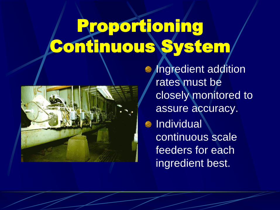
Proportioning
Continuous System
Ingredient addition
rates must be
closely monitored to
assure accuracy.
Individual
continuous scale
feeders for each
ingredient best.

Mixing
Batch System
Cycle time must be long enough to fully mix dry ingredients and added liquids.
Cycle time must allow time for filling and discharging the mixer.
Size of mixer based on required mixing time.
Standard ribbon mixer requires 3-5 minutes for mixing.
Twin rotor and special agitator mixers can fully mix in 1-1 ½ minutes.

Mixing
Batch System
Cycle time example:
Design capacity = 75 MTPH
Assume 4 metric ton capacity mixer
Batches per hour = 75/4 = 18.75
Cycle time = 60/18.75 = 3.2 minutes
Cycle time = 3.2 x 60 = 192 seconds

Mixing
Batch System
Cycle time = 3.2 x 60 = 192 seconds
Assumptions
Mxer fill time = 15 seconds
Mixer discharge time = 15 seconds
Mixing time = 192-30 = 162 seconds
Mixer must be able to fully mix in 2.7 minutes

Batching Scale & Mixer
Mixer
Scale Hopper
Inter-vent
Surge Bin
Liquid Manifold

Twin Rotor Mixer
Mixer
Inter-vent
Surge Bin

Pelleting System

Pelleting System
Capacity is dependent on drive
horsepower.
Capacity varies by ingredients used,
liquid added, and pellet size.
A minimum of 2 mash bins should be
located above mill.

Pelleting System
Horizontal Cooler
18-21 cubic meters per minute of air per metric ton of capacity.
High maintenance.
Conterflow Cooler
12-16 cubic meters per minute of air per metric ton of capacity
Low maintenance .

Bagging System
Manual bag
placement and
sealing.
Requires 1-2 people
to operate at
capacity. Manual System
6-8 bags per minute

Bagging System
Automatic bag
placement, filling
and sealing.
Requires restocking
of new bags in bag
hanger. Automated System
18-20 bags per minute

Bagging System
Bagging system capacity based on
amount to be bagged and time allowed
to do it.
A minimum of 2 supply bins should be
placed above packing system.
Supply bin capacity based on batch or
lot size to be bagged.

Warehousing

Warehousing
Allow adequate space for storage of individual bagged products and supplies.
Products should be arranged so oldest products are used first (FIFO).
Products should be located in warehouse to minimize travel distances to and fvrom storage area.
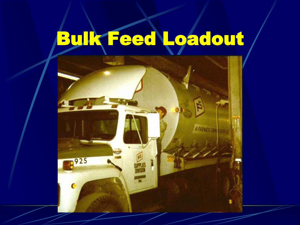
Bulk Feed Loadout

Bulk Feed Loadout
Scaled weight
required for selling
product.
1. Truck scale
2. Weigh Lorry
3. Batch weight

Bulk Feed Loadout Bins
Number of bulk product bins based on
amount of feed made, number of
products made, truck capacity, available
loading time, scheduling.
Capacity of bulk product bins based on
lot size, batch size or use requirements.
Summary
The product mix for the facility must be clearly identified and understood.
Production requirements for each type of product must be determined to identify equipment needed.
Plant capacities both current and future must be determined to make sure key systems will handle all capacity levels.

Summary
The process flow of the mill must be
defined and drawn before any physical
layout of the mill is started.
Provision for future equipment and
systems must be included in initial mill
design.