. The sliding](https://static.fdocuments.net/doc/165x107/5b31d5f57f8b9a81728bfff7/correlation-between-coefficient-of-simulation-52-of-fe14mn55si12cr5ni010c.jpg)
Features - Sealed Performance Batteries · Acc. to IEC 896-2 (25°C/77°F) 0.25C 0.15C 0.10C 1C...
2
L H HT W RECHARGEABLE DCG 12-70 12 Volt 70.0 A.H. @ 20-hr. rate to 1.80V 65.1 A.H. @ 10-hr. rate to 1.80V POWER-GEL SERIES GEL BATTERY ® ™ Power-Sonic Corporation Pb www.power-sonic.com ® Tolerances are +/- 0.08 in. (+/- 2mm) for height dimensions. All data subject to change without notice. Physical Dimensions: in(mm) Features Thixotropic gel electrolyte for enhanced performance Valve regulated, spill proof construction allows safe operation in any position Superior capabilities Power/volume ratio yielding unrivaled energy density Rugged ABS plastic (UL94-HB) case and cover Approved for transport by air. D.O.T., I.A.T.A., F.A.A. and C.A.B. certified U.L. recognized - MH 20845 CE compliant • • • • • • • • www.power-sonic.com To ensure safe and efficient operation always refer to the latest edition of our Technical Manual, as published on our website. All data subject to change without notice. Terminals (mm) Performance Specifications Nominal Voltage............................................................................ 12 volts (6 cells) Nominal Capacity 20-hr. (3.50A to 10.8 volts) ............................................................ 70.0 AH 10-hr. (6.51A to 10.5 volts) ............................................................. 65.1 AH 5-hr. (11.2A to 10.5 volts) ............................................................ 56.0 AH 3-hr. (16.2A to 10.5 volts) ............................................................ 48.6 AH 1-hr. (38.5A to 10.0 volts) ............................................................ 38.5 AH Approximate Weight .............................................................. 50.71 lbs. (23.0 kg) Energy Density (20-hr. rate) .................................... 1.52 W-h/in3 (92.83 W-h/l) Specific Energy (20-hr. rate) ................................. 16.93 W-h/lb (37.33 W-h/kg) Internal Resistance (approx.) ......................................................... 7.9 milliohms Shelf Life (% of nominal capacity at 68°F (20°C)) 1 Month ...................................................................................................... 97% 3 Months..................................................................................................... 91% 6 Months .................................................................................................... 83% Operating Temperature Range Charge .. ........................................................... -4°F (-20°C) to 122°F (50°C) Discharge ....................................................... -40°F (-40°C) to 140°F (60°C) Case ..................................................................................... ABS Plastic (UL94 HB) Recommended Power-Sonic Chargers ............................................................. n/a L: 10.20 (259) W: 6.61 (168) H: 8.19 (208) HT: 8.43 (214) DCG12-70 12 Volt 70.0 AH @ 20-hr. rate 65.1 AH @ 10-hr. rate 18 22 17.4 10 10 9 9 8.5 8.5 13 18 22 15.9 13 U: Positive Terminal T6 U: Negative Terminal 16 6 M6 T6: Threaded insert w. 6 mm stud fastener U: Universal terminals: Heavy-duty posts with ‘nut & bolt’ fasteners • •
Transcript of Features - Sealed Performance Batteries · Acc. to IEC 896-2 (25°C/77°F) 0.25C 0.15C 0.10C 1C...

L
HHT
W
RECHARGEABLE
DCG 12-7012 Volt 70.0 A.H. @ 20-hr. rate to 1.80V
65.1 A.H. @ 10-hr. rate to 1.80V
POWER-GEL SERIES
GEL BATTERY
®
™
Power-Sonic Corporation
BAT
T ERY
MUSTBERECYC
LED
PbNONSPILLABLE
www.power-sonic.com
MH20845
®
Tolerances are +/- 0.08 in. (+/- 2mm) for height dimensions. All data subject to change without notice.
Physical Dimensions: in(mm)
Features
Thixotropic gel electrolyte for enhanced performance Valve regulated, spill proof construction allows safe operation in any position
Superior capabilitiesPower/volume ratio yielding unrivaled energy density
Rugged ABS plastic (UL94-HB) case and cover Approved for transport by air. D.O.T., I.A.T.A., F.A.A. and C.A.B. certifi ed
U.L. recognized - MH 20845CE compliant
••
••••
••
www.power-sonic.comTo ensure safe and effi cient operation always refer to the latest edition of our Technical Manual, as published on our website.All data subject to change without notice.
Terminals (mm) Performance Specifi cations
Nominal Voltage ............................................................................ 12 volts (6 cells)
Nominal Capacity
20-hr. (3.50A to 10.8 volts) ............................................................ 70.0 AH
10-hr. (6.51A to 10.5 volts) ............................................................. 65.1 AH
5-hr. (11.2A to 10.5 volts) ............................................................ 56.0 AH
3-hr. (16.2A to 10.5 volts) ............................................................ 48.6 AH
1-hr. (38.5A to 10.0 volts) ............................................................ 38.5 AH
Approximate Weight .............................................................. 50.71 lbs. (23.0 kg)
Energy Density (20-hr. rate) .................................... 1.52 W-h/in3 (92.83 W-h/l)
Specifi c Energy (20-hr. rate) ................................. 16.93 W-h/lb (37.33 W-h/kg)
Internal Resistance (approx.) ......................................................... 7.9 milliohms
Shelf Life (% of nominal capacity at 68°F (20°C))
1 Month ...................................................................................................... 97%
3 Months ..................................................................................................... 91%
6 Months .................................................................................................... 83%
Operating Temperature Range
Charge .. ........................................................... -4°F (-20°C) to 122°F (50°C)
Discharge ....................................................... -40°F (-40°C) to 140°F (60°C)
Case .....................................................................................ABS Plastic (UL94 HB)
Recommended Power-Sonic Chargers .............................................................n/aL: 10.20 (259) W: 6.61 (168) H: 8.19 (208) HT: 8.43 (214)
DCG12-70 12 Volt 70.0 AH @ 20-hr. rate
65.1 AH @ 10-hr. rate
18 22
17.4
10 10
9 9
8.5
8.5
13
18 22
15.9
13
U: Positive TerminalT6 U: Negative Terminal
16
6
M6
T6: Threaded insert w. 6 mm stud fastener
U: Universal terminals: Heavy-duty posts with ‘nut & bolt’ fasteners
•
•
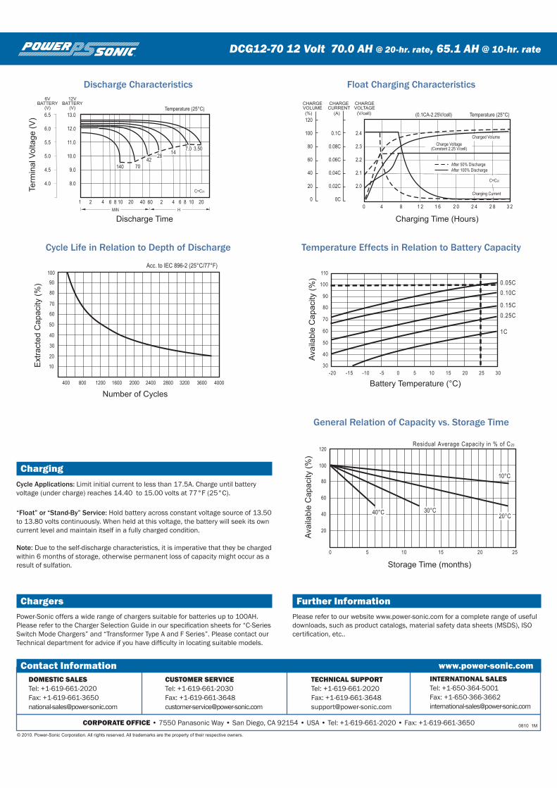
ChargingCycle Applications: Limit initial current to less than 17.5A. Charge until battery voltage (under charge) reaches 14.40 to 15.00 volts at 77°F (25°C).
“Float” or “Stand-By” Service: Hold battery across constant voltage source of 13.50 to 13.80 volts continuously. When held at this voltage, the battery will seek its own current level and maintain itself in a fully charged condition.
Note: Due to the self-discharge characteristics, it is imperative that they be charged within 6 months of storage, otherwise permanent loss of capacity might occur as a result of sulfation.
ChargersPower-Sonic offers a wide range of chargers suitable for batteries up to 100AH. Please refer to the Charger Selection Guide in our specification sheets for “C-Series Switch Mode Chargers” and “Transformer Type A and F Series”. Please contact our Technical department for advice if you have difficulty in locating suitable models.
®
DCG12-70 12 Volt 70.0 AH @ 20-hr. rate, 65.1 AH @ 10-hr. rate
0 5 10 15 20 25
20
40
60
80
100
120Residual Average Capacity in % of C20
Storage Time (months)
Avai
labl
e C
apac
ity (%
)
40°C 30°C20°C
10°C
30
40
60
80
20
10
50
70
90
100
25 30
30
40
60
80
110
50
70
90
100
-20 -15 0 15 20-10 -5 5 10
Battery Temperature (°C)
Avai
labl
e C
apac
ity (%
)
Number of Cycles
Ext
ract
ed C
apac
ity (%
)
400 800 1200 1600 2000 2400 2800 3200 3600 4000
Acc. to IEC 896-2 (25°C/77°F)
0.25C
0.15C
0.10C
1C
0.05C
1 2 4 6 8 10 20 40 60 2 4 6 8 10 20
HMIN
C=C20
Discharge Time
Term
inal
Vol
tage
(V)
Temperature (25°C)
6.5
6.0
5.5
5.0
4.5
4.0
13.0
12.0
11.0
10.0
9.0
8.0
6VBATTERY
(V)
12VBATTERY
(V)
3.507.014
2842
70140
0 4 8 1 2 1 6 2 0 2 4 2 8 3 2
Charging Time (Hours)
Temperature (25°C)
Charged Volume
Charge Voltage
(Constant 2.25 V/cell)
C=C20
After 50% Discharge
After 100% Discharge
Charging Current
(0.1CA-2.25V/cell)
120
100
80
60
40
20
0
0.1C
0.08C
0.06C
0.04C
0.02C
2.4
2.3
2.2
2.1
2.0
0C
CHARGEVOLUME
CHARGECURRENT
CHARGEVOLTAGE
(%) (A) (V/cell)
Discharge Characteristics
Cycle Life in Relation to Depth of Discharge Temperature Effects in Relation to Battery Capacity
Float Charging Characteristics
General Relation of Capacity vs. Storage Time
0 5 10 15 20 25
20
40
60
80
100
120Residual Average Capacity in % of C20
Storage Time (months)
Avai
labl
e C
apac
ity (%
)
40°C 30°C20°C
10°C
30
40
60
80
20
10
50
70
90
100
25 30
30
40
60
80
110
50
70
90
100
-20 -15 0 15 20-10 -5 5 10
Battery Temperature (°C)
Avai
labl
e C
apac
ity (%
)
Number of Cycles
Ext
ract
ed C
apac
ity (%
)
400 800 1200 1600 2000 2400 2800 3200 3600 4000
Acc. to IEC 896-2 (25°C/77°F)
0.25C
0.15C
0.10C
1C
0.05C
1 2 4 6 8 10 20 40 60 2 4 6 8 10 20
HMIN
C=C20
Discharge Time
Term
inal
Vol
tage
(V)
Temperature (25°C)
6.5
6.0
5.5
5.0
4.5
4.0
13.0
12.0
11.0
10.0
9.0
8.0
6VBATTERY
(V)
12VBATTERY
(V)
3.507.014
2842
70140
0 4 8 1 2 1 6 2 0 2 4 2 8 3 2
Charging Time (Hours)
Temperature (25°C)
Charged Volume
Charge Voltage
(Constant 2.25 V/cell)
C=C20
After 50% Discharge
After 100% Discharge
Charging Current
(0.1CA-2.25V/cell)
120
100
80
60
40
20
0
0.1C
0.08C
0.06C
0.04C
0.02C
2.4
2.3
2.2
2.1
2.0
0C
CHARGEVOLUME
CHARGECURRENT
CHARGEVOLTAGE
(%) (A) (V/cell)
Further InformationPlease refer to our website www.power-sonic.com for a complete range of useful downloads, such as product catalogs, material safety data sheets (MSDS), ISO certification, etc..
CORPORATE OFFICE • 7550 Panasonic Way • San Diego, CA 92154 • USA • Tel: +1-619-661-2020 • Fax: +1-619-661-3650
CUSTOMER SERVICETel: +1-619-661-2030 Fax: [email protected]
INTERNATIONAL SALESTel: +1-650-364-5001 Fax: [email protected]
DOMESTIC SALESTel: +1-619-661-2020Fax: [email protected]
TECHNICAL SUPPORTTel: +1-619-661-2020 Fax: [email protected]
Contact Information www.power-sonic.com
0810 1M
© 2010. Power-Sonic Corporation. All rights reserved. All trademarks are the property of their respective owners.


