Features · Random vibration test 5Hz to 150Hz, Z-Axis 1.01m/s² (0.103Grms), Y-Axis, X-Axis...
9
20 Watt 2“ x 1“ Single and Dual Output Features Regulated Converter • Wide 4:1 input voltage range • 2.25kVDC isolation • Efficiency up to 89% • Six-sided continuous shield • EN50155, UL/IEC/EN60950-1 certified Description The RP20-FR series wide range input DC/DC converters are certified to UL60950-1 and cUL 60950-1. This makes them ideal for all telecom and industrial applications where approved safety standards are required. The 110VDC input versions have been especially designed for railway applications. RP20-FR DC/DC Converter www.recom-power.com REV.: 6/2020 PD-1 EN50155 certified UL60950-1 certified IEC/EN60950-1 certified EN55032 compliant EN55024 compliant EN50121-3-2 compliant R E C O M C O N V E R T E R S C O M P L I A N T P R O D U C T S REACH REACH compliant compliant E196683 R E C O M C O N V E R T E R S C O M P L I A N T P R O D U C T S RoHS RoHS 2 2 + + compliant compliant 10 from 10 10 from 10 Y E A R w a r r a n t y 3 Selection Guide Model Numbering Notes: Note2: no suffix for CTRL function with positive logic (1=ON, 0=OFF) add suffix “N” for CTRL function with negative logic (0=ON, 1=OFF) or add suffix “XC” for omitted CTRL pin (refer to “Dimension Drawing (mm)”) Note3: add suffix “-HC” for premounted Heat-sink with clamps nom. Input Voltage nom. Output Voltage Single or Dual RP20-__ __ _FR/_- _ Part Number Input Output Output Input (1) Efficiency (1) Max. Capacitive Voltage Range Voltage Current Current typ. Load [VDC] [VDC] [mA] [mA] [%] [µF] RP20-243.3SFR (2,3) 9-36 3.3 4500 728 85 7000 RP20-2405SFR (2,3) 9-36 5 4000 947 88 5000 RP20-2412SFR (2,3) 9-36 12 1670 938 89 850 RP20-2415SFR (2,3) 9-36 15 1330 945 88 700 RP20-483.3SFR (2,3) 18-75 3.3 4500 364 85 7000 RP20-4805SFR (2,3) 18-75 5 4000 473 88 5000 RP20-4812SFR (2,3) 18-75 12 1670 469 89 850 RP20-4815SFR (2,3) 18-75 15 1330 467 89 700 RP20-1103.3SFR (2,3) 43-160 3.3 4500 159 85 7000 RP20-11005SFR (2,3) 43-160 5 4000 209 87 5000 RP20-11012SFR (2,3) 43-160 12 1670 207 88 850 RP20-11015SFR (2,3) 43-160 15 1330 206 88 700 RP20-2412DFR (2,3) 9-36 ±12 ±833 947 88 ±500 RP20-2415DFR (2,3) 9-36 ±15 ±667 937 89 ±350 RP20-4812DFR (2,3) 18-75 ±12 ±833 473 88 ±500 RP20-4815FDFR (2,3) 18-75 ±15 ±667 468 89 ±350 RP20-11012DFR (2,3) 43-160 ±12 ±833 207 88 ±500 RP20-11015DFR (2,3) 43-160 ±15 ±667 204 89 ±350 Ordering Examples RP20-2405SFR = 24V input, 5V output, single, positive Logic CTRL pin RP20-4812DFR/N-HC = 48V input, ±12V output, dual, negative Logic CTRL pin, Heat-sink premounted RP20-11005SFR/XC = 110V input, 5V output, single, no CTRL pin Notes: Note1: Maximum values at nominal input voltage and full load “Package (3) ” “CTRL Logic (2) ”
Transcript of Features · Random vibration test 5Hz to 150Hz, Z-Axis 1.01m/s² (0.103Grms), Y-Axis, X-Axis...
20 Watt2“ x 1“Single and DualOutput
Features
Regulated Converter
• Wide 4:1 input voltage range
• 2.25kVDC isolation
• Efficiency up to 89%
• Six-sided continuous shield
• EN50155, UL/IEC/EN60950-1 certified
DescriptionThe RP20-FR series wide range input DC/DC converters are certified to UL60950-1 and cUL 60950-1.This makes them ideal for all telecom and industrial applications where approved safety standards arerequired. The 110VDC input versions have been especially designed for railway applications.
RP20-FR
DC/DC Converter
www.recom-power.com REV.: 6/2020 PD-1
EN50155 certifiedUL60950-1 certifiedIEC/EN60950-1 certifiedEN55032 compliantEN55024 compliantEN50121-3-2 compliant
RE
COM
CONVERTERS
CO
MPLIANT PROD
U
CTS
REACHREACHcompliantcompliant
E196683
RE
COM
CONVERTERS
CO
MPLIANT PROD
U
CTS
RoHSRoHS 22++compliantcompliant10 from 1010 from 10
YEAR
war ran t
y3
Selection Guide
Model Numbering
Notes: Note2: no suffix for CTRL function with positive logic (1=ON, 0=OFF) add suffix “N” for CTRL function with negative logic (0=ON, 1=OFF) or add suffix “XC” for omitted CTRL pin (refer to “Dimension Drawing (mm)”) Note3: add suffix “-HC” for premounted Heat-sink with clamps
nom. Input Voltage
nom. Output Voltage
Single or Dual
RP20-__ __ _FR/_- _
Part Number Input Output Output Input (1) Efficiency (1) Max. Capacitive Voltage Range Voltage Current Current typ. Load [VDC] [VDC] [mA] [mA] [%] [µF]RP20-243.3SFR (2,3) 9-36 3.3 4500 728 85 7000RP20-2405SFR (2,3) 9-36 5 4000 947 88 5000 RP20-2412SFR (2,3) 9-36 12 1670 938 89 850RP20-2415SFR (2,3) 9-36 15 1330 945 88 700RP20-483.3SFR (2,3) 18-75 3.3 4500 364 85 7000RP20-4805SFR (2,3) 18-75 5 4000 473 88 5000RP20-4812SFR (2,3) 18-75 12 1670 469 89 850RP20-4815SFR (2,3) 18-75 15 1330 467 89 700RP20-1103.3SFR (2,3) 43-160 3.3 4500 159 85 7000RP20-11005SFR (2,3) 43-160 5 4000 209 87 5000RP20-11012SFR (2,3) 43-160 12 1670 207 88 850RP20-11015SFR (2,3) 43-160 15 1330 206 88 700RP20-2412DFR (2,3) 9-36 ±12 ±833 947 88 ±500RP20-2415DFR (2,3) 9-36 ±15 ±667 937 89 ±350RP20-4812DFR (2,3) 18-75 ±12 ±833 473 88 ±500RP20-4815FDFR (2,3) 18-75 ±15 ±667 468 89 ±350RP20-11012DFR (2,3) 43-160 ±12 ±833 207 88 ±500RP20-11015DFR (2,3) 43-160 ±15 ±667 204 89 ±350
Ordering ExamplesRP20-2405SFR = 24V input, 5V output, single, positive Logic CTRL pinRP20-4812DFR/N-HC = 48V input, ±12V output, dual, negative Logic CTRL pin, Heat-sink premountedRP20-11005SFR/XC = 110V input, 5V output, single, no CTRL pin
Notes: Note1: Maximum values at nominal input voltage and full load
“Package (3)”
“CTRL Logic (2)”

www.recom-power.com REV.: 6/2020 PD-2
DC/DC ConverterRP20-FR
SeriesSpecifications (measured @ Ta= 25°C, nom. Vin, full load unless otherwise stated)
BASIC CHARACTERISTICSParameter Condition Min. Typ. Max.
Input Filternom. Vin = 24VDC, nom. Vin = 48VDC
nom. Vin = 110VDCCommon Mode Choke
Pi-Type
Input Voltage Rangenom. Vin = 24VDCnom. Vin = 48VDC
nom. Vin = 110VDC
9VDC18VDC43VDC
24VDC48VDC
110VDC
36VDC75VDC160VDC
Input Surge Voltage 100s max.nom. Vin = 24VDCnom. Vin = 48VDC
nom. Vin = 110VDC
50VDC100VDC170VDC
Under Voltage Lockout (UVLO)
nom. Vin = 24VDCDC-DC ONDC-DC OFF 8VDC
9VDC
nom. Vin = 48VDCDC-DC ONDC-DC OFF 16VDC
18VDC
nom. Vin = 110VDCDC-DC ONDC-DC OFF 40VDC
43VDC
Output Voltage Trimming refer to “OUTPUT VOLTAGE TRIMMING” -10% +10%
Input Reflected Ripple Current 30mAp-p
Start-up TimePower up
ON/OFF CTRL30ms30ms
ON/OFF CTRL (4)
Positive LogicDC-DC ONDC-DC OFF
Open or 3.0VDC < VCTRL< 15VDCShort or 0VDC < VCTRL< 1.2VDC
Negative LogicDC-DC ONDC-DC OFF
Short or 0VDC < VCTRL< 1.2VDCOpen or 3.0VDC < VCTRL< 15VDC
Input Current of CTRL pin DC-DC ON -0.5mA +1.0mA
Standby Current DC-DC OFF 2.5mA
Internal Operating Frequency 297kHz 330kHz 363kHz
Ripple and Noisemeasured at 20MHz BW
with a 1µF/50V X7R MLCC3.3Vout, 5Vout12Vout, 15Vout
75mVp-p100mVp-p
continued on next page
Notes: Note4: If suffix “XC” is specified, pin6 will be absent. If fitted, the ON/OFF control function can be positive or negative logic. The pin voltage is referenced to -Vin pin
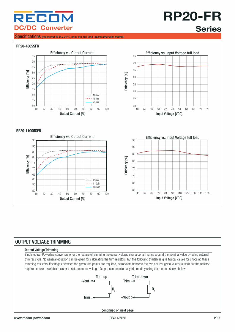
Efficiency vs. Output Current Efficiency vs. Input Voltage full load
9Vin24Vin36Vin
Effic
ienc
y [%
]
Output Current [%]10
50
55
60
65
70
75
90
95
20 40 60 80 10030 50 70 90
80
85
Effic
ienc
y [%
]
Input Voltage [VDC]9
65
60
70
75
80
85
95
15 18 24 30 3612 21 27 33
90
RP20-2405SFR
www.recom-power.com REV.: 6/2020 PD-3
DC/DC ConverterSpecifications (measured @ Ta= 25°C, nom. Vin, full load unless otherwise stated)
RP20-FRSeries
Efficiency vs. Output Current
Efficiency vs. Output Current
Efficiency vs. Input Voltage full load
Efficiency vs. Input Voltage full load
18Vin48Vin75Vin
Effic
ienc
y [%
]
Output Current [%]10
50
55
60
65
75
70
90
95
20 40 60 80 10030 50 70 90
80
85
43Vin110Vin160Vin
Effic
ienc
y [%
]
Output Current [%]10
50
55
60
65
70
75
95
90
85
20 40 60 80 10030 50 70 90
80
Effic
ienc
y [%
]
Input Voltage [VDC]18
65
60
70
75
80
85
95
30 36 48 60 66 7524 42 54 72
90
Effic
ienc
y [%
]
Input Voltage [VDC]43
65
60
70
75
80
85
95
62 72 96 125 16014352 84 110 136
90
RP20-4805SFR
RP20-11005SFR
OUTPUT VOLTAGE TRIMMING
continued on next page
Output Voltage TrimmingSingle output Powerline converters offer the feature of trimming the output voltage over a certain range around the nominal value by using external trim resistors. No general equation can be given for calculating the trim resistors, but the following trimtables give typical values for choosing these trimming resistors. If voltages between the given trim points are required, extrapolate between the two nearest given values to work out the resistor required or use a variable resistor to set the output voltage. Output can be externally trimmed by using the method shown below.
RU
RD
Trim
+VoutTrim
-VoutTrim up Trim down

www.recom-power.com REV.: 6/2020 PD-4
DC/DC ConverterSpecifications (measured @ Ta= 25°C, nom. Vin, full load unless otherwise stated)
RP20-FRSeries
Trim up 1 2 3 4 5 6 7 8 9 10 [%]
Vout = 3.333 3.366 3.399 3.432 3.465 3.498 3.531 3.564 3.597 3.63 [VDC]
RU = 385.07 191.51 126.99 94.73 75.37 62.47 53.25 46.34 40.96 36.66 [kW]
Trim down 1 2 3 4 5 6 7 8 9 10 [%]
Vout = 3.267 3.234 3.201 3.168 3.135 3.102 3.069 3.036 3.003 2.97 [VDC]
RD = 116.72 54.78 34.13 23.81 17.62 13.49 10.54 8.33 6.60 5.23 [kW]
Trim up 1 2 3 4 5 6 7 8 9 10 [%]
Vout = 5.05 5.10 5.15 5.20 5.25 5.30 5.35 5.4 5.45 5.50 [VDC]
RU = 253.45 125.70 83.18 61.83 49.05 40.53 34.45 29.89 26.34 23.50 [kW]
Trim down 1 2 3 4 5 6 7 8 9 10 [%]
Vout = 4.95 4.90 4.85 4.80 4.75 4.70 4.65 4.60 4.55 4.50 [VDC]
RD = 248.34 120.59 78.01 56.72 43.94 35.42 29.34 24.78 21.23 18.39 [kW]
Trim up 1 2 3 4 5 6 7 8 9 10 [%]
Vout = 12.12 12.24 12.36 12.48 12.60 12.72 12.84 12.96 13.08 13.20 [VDC]
RU = 203.22 99.06 64.33 46.97 36.56 29.61 24.65 20.93 18.04 15.72 [kW]
Trim down 1 2 3 4 5 6 7 8 9 10 [%]
Vout = 11.88 11.76 11.64 11.52 11.40 11.28 11.16 11.04 10.92 10.8 [VDC]
RD = 776.56 380.72 248.78 182.81 143.22 116.83 97.99 83.84 72.85 64.06 [kW]
Trim up 1 2 3 4 5 6 7 8 9 10 [%]
Vout = 15.15 15.3 15.45 15.60 15.75 15.90 16.05 16.20 16.35 16.50 [VDC]
RU = 161.56 78.22 50.45 36.56 28.22 22.67 18.70 15.72 13.41 11.56 [kW]
Trim down 1 2 3 4 5 6 7 8 9 10 [%]
Vout = 14.85 14.70 14.55 14.40 14.25 14.10 13.95 13.80 13.65 13.50 [VDC]
RD = 818.22 401.56 262.67 193.22 151.56 123.78 103.94 89.06 77.48 68.22 [kW]
RP20-xx3.3SFR
RP20-xx05SFR
RP20-xx12SFR
RP20-xx15SFR
REGULATIONSParameter Condition ValueOutput Accuracy ±1.0%
Line Regulationlow line to high line,
full loadSingle Dual
±0.2%±0.5%
Load Regulation
0% to 100% loadSingle Dual
±0.2%±1.0%
10% to 90% loadSingle Dual
±0.1%±0.8%
Cross Regulation asymmetrical 25%<>100% load ±5.0%
Transient Response Recovery Time 25% load step change 250µs typ.
www.recom-power.com REV.: 6/2020 PD-5
DC/DC ConverterSpecifications (measured @ Ta= 25°C, nom. Vin, full load unless otherwise stated)
RP20-FRSeries
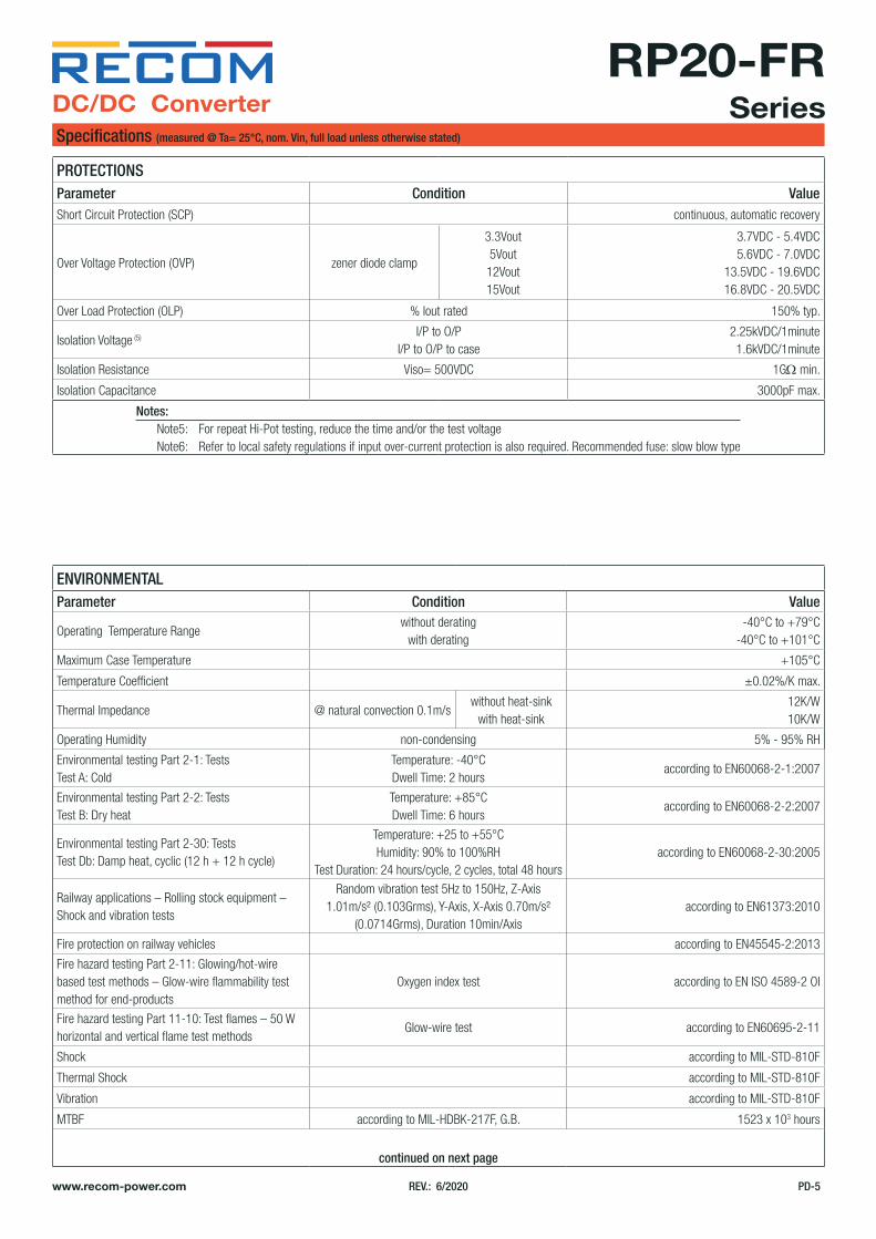
PROTECTIONSParameter Condition ValueShort Circuit Protection (SCP) continuous, automatic recovery
Over Voltage Protection (OVP) zener diode clamp
3.3Vout5Vout
12Vout15Vout
3.7VDC - 5.4VDC5.6VDC - 7.0VDC
13.5VDC - 19.6VDC16.8VDC - 20.5VDC
Over Load Protection (OLP) % Iout rated 150% typ.
Isolation Voltage (5)I/P to O/P
I/P to O/P to case2.25kVDC/1minute
1.6kVDC/1minute
Isolation Resistance Viso= 500VDC 1GW min.
Isolation Capacitance 3000pF max.
ENVIRONMENTALParameter Condition Value
Operating Temperature Rangewithout derating
with derating-40°C to +79°C
-40°C to +101°C
Maximum Case Temperature +105°C
Temperature Coefficient ±0.02%/K max.
Thermal Impedance @ natural convection 0.1m/swithout heat-sink
with heat-sink12K/W10K/W
Operating Humidity non-condensing 5% - 95% RH
Environmental testing Part 2-1: TestsTest A: Cold
Temperature: -40°C Dwell Time: 2 hours
according to EN60068-2-1:2007
Environmental testing Part 2-2: TestsTest B: Dry heat
Temperature: +85°C Dwell Time: 6 hours
according to EN60068-2-2:2007
Environmental testing Part 2-30: TestsTest Db: Damp heat, cyclic (12 h + 12 h cycle)
Temperature: +25 to +55°C Humidity: 90% to 100%RH
Test Duration: 24 hours/cycle, 2 cycles, total 48 hoursaccording to EN60068-2-30:2005
Railway applications – Rolling stock equipment – Shock and vibration tests
Random vibration test 5Hz to 150Hz, Z-Axis 1.01m/s² (0.103Grms), Y-Axis, X-Axis 0.70m/s²
(0.0714Grms), Duration 10min/Axisaccording to EN61373:2010
Fire protection on railway vehicles according to EN45545-2:2013
Fire hazard testing Part 2-11: Glowing/hot-wire based test methods – Glow-wire flammability test method for end-products
Oxygen index test according to EN ISO 4589-2 OI
Fire hazard testing Part 11-10: Test flames – 50 W horizontal and vertical flame test methods
Glow-wire test according to EN60695-2-11
Shock according to MIL-STD-810F
Thermal Shock according to MIL-STD-810F
Vibration according to MIL-STD-810F
MTBF according to MIL-HDBK-217F, G.B. 1523 x 103 hours
continued on next page
Notes: Note5: For repeat Hi-Pot testing, reduce the time and/or the test voltage Note6: Refer to local safety regulations if input over-current protection is also required. Recommended fuse: slow blow type

www.recom-power.com REV.: 6/2020 PD-6
DC/DC ConverterSpecifications (measured @ Ta= 25°C, nom. Vin, full load unless otherwise stated)
RP20-FRSeries
Notes: Note7: Derating graphs are valid only for the shown part numbers. If you need detailed derating-information about a part-number not shown here please contact RECOM Techsupport for detailed information
Derating Graph (7)
-40 60 8079
100101
12040200-200
20
40
60
80
100
Ambient Temperature [°C]
Outp
ut P
ower
[%]
-40 60 8085
100101
12040200-200
20
40
60
80
100
Ambient Temperature [°C]
Outp
ut P
ower
[%]
RP20-2415SFR RP20-2415SFR-HC
SAFETY AND CERTIFICATIONSCertificate Type (Safety) Condition Standard
Information Technology Equipment, General Requirements for Safety E196683UL60950-1, 2nd Edition, 2014
CAN/CSA-C22.2 No. 60950-1-07, 2nd Edition, 2014
Information Technology Equipment, General Requirements for Safety (LVD)
TW1708011-001IEC60950-1:2005, 2nd Edition + A2:2013
EN60950-1:2006 + A2:2013
Railway Applications - Electrical Equipment used on rolling stock 15A100702E-C EN50155:2007
EAC RU-AT.49.09571 TP TC 004/2011
RoHS2 RoHS-2011/65/EU + AM-2015/863
EMC Compliance (Railway) Condition Standard / CriterionRailway Applications - Electromagnetic Compatibility EN50121-3-2:2006
ESD Electrostatic Discharge Immunity TestAir ±2, ±4, ±8kV
Contact ±2, ±4, ±6kVEN61000-4-2, Criteria A
Radiated, Radio-Frequency, Electromagnetic Field Immunity Test20V/m (80-1000MHz)
10V/m (1400-2100MHz)5V/m (2100-2500MHz)
EN61000-4-3, Criteria A
Fast Transient and Burst Immunity (8) DC Power Port: ±2kV EN61000-4-4, Criteria A
Surge Immunity (8)DC Power Port: L-L ±0.5, 1kV
DC Power Port: L-E ±0.5, 1, 2kVEN61000-4-5, Criteria A
Immunity to Conducted Disturbances, Induced by Radio-Frequency Fields DC Power Port: 10V EN61000-4-6, Criteria A
continued on next page

www.recom-power.com REV.: 6/2020 PD-7
DC/DC ConverterSpecifications (measured @ Ta= 25°C, nom. Vin, full load unless otherwise stated)
RP20-FRSeries
EMC Compliance (Multimedia) Condition Standard / CriterionIndustrial, scientific and medical equipment - Radio frequencydisturbance characteristics - Limits and methods of measurement
without external filterwithout external filter
EN55011, Class AEN55011, Class B
Electromagnetic compatibility of multimedia equipment - Emission requirements (24Vin and 48Vin)
without external filterwithout external filter
EN55032, Class AEN55032, Class B
Electromagnetic compatibility of multimedia equipment - Emission requirements (110Vin)
without external filterwith external filter
EN55032, Class AEN55032, Class B
Information Technology Equipment - Immunity Characteristics - Limits and Methods of Measurement
EN55024:2010 + A1:2015
ESD Electrostatic Discharge Immunity TestAir ±2, ±4, ±8kV
Contact ±2, ±4, ±6kVIEC61000-4-2:2008, Criteria A
Radiated, Radio-Frequency, Electromagnetic Field Immunity Test 20V/m (80-1000MHz) IEC61000-4-3:2006 + A2:2010, Criteria A
Fast Transient and Burst Immunity DC Power Port: ±2kV IEC61000-4-4:2012, Criteria A
Surge Immunity DC Power Port: ±0.5, ±1, ±2kV IEC61000-4-5:2014, Criteria A
Immunity to Conducted Disturbances, Induced by Radio-Frequency Fields DC Power Port: 10V IEC61000-4-6:2013, Criteria A
Power Magnetic Field Immunity 50Hz 1A/m IEC61000-4-8:2009, Criteria A
Notes: Note8: An external input filter capacitor is required if the module has to meet EN61000-4-4, -5 The filter Recom suggests: 24VDC and 48VDC input. Nippon chemi-con KY series, 220µF/100V 110VDC input: Rubycon BXF series, 100µF/250V
F1 L1
Com
C1 C2 C3 C4
-Vout
+Vout
-Vin
+Vin
C5
F1 L1
C1 C2 C3 C4
-Vin
+Vin
C5
+Vout+Vin
-Vout-Vin
-Vout
+Vout+Vout+Vin
-Vout-Vin
Com
F1 L1
Com
C1 C2 C3 C4
-Vout
+Vout
-Vin
+Vin
C5
F1 L1
C1 C2 C3 C4
-Vin
+Vin
C5
+Vout+Vin
-Vout-Vin
-Vout
+Vout+Vout+Vin
-Vout-Vin
Com
EMI Filtering according to EN55032 Class B (110Vin Single)
MODEL C1 C2/C3/C4 C5 L1
RP20-110xxSFRRP20-110xxDFR
39µF/250VAl Cap. (lie down)
Rubycon BX
0.47µF/250V1812 MLCC
1000pF/3kV1808 MLCC
CMC: 470µHref.: WE-SL5 744272471
EMI Filtering according to EN55032 Class B (110Vin Dual)
Component List

www.recom-power.com REV.: 6/2020 PD-8
DC/DC ConverterSpecifications (measured @ Ta= 25°C, nom. Vin, full load unless otherwise stated)
RP20-FRSeries
DIMENSIONS and PHYSICAL CHARACTERISTICSParameter Type Value
Materialcasebase
potting
nickel coated copperFR4 PCB
silicone (UL94 V-0)
Dimensions (LxWxH)without Heat-sink
with Heat-sink50.8 x 25.4 x 10.2mm56.8 x 25.4 x 16.8mm
Weightwithout Heat-sink
with Heat-sink30g
40.89g
Ø 1.0±0.1
5.610
.2
8 x 2.54= 20.32 15.20
Top View
2.54
7.62
10.2
50.8 25.4
5.08
12.7
0
2
3
4
5
1Bottom View
14
5
2
6
2.54
2.54
63
Pinning InformationPin # Single Dual
1 +Vin +Vin
2 -Vin -Vin
3 +Vout +Vout
4 Trim (4) Com
5 -Vout -Vout6 CTRL(2) CTRL(2)
Tolerance: xx.x= ±0.5mm xx.xx= ±0.25mm
Dimension Drawing (mm)
Recommended Footprint Details
Dimension Drawing with Heat-sink (mm)
Ø 1.0±0.18 x 2.54= 20.32 15.20
Top View
2.54
7.62
10.2
5.08
12.7
0
2
3
4
5
1Bottom View
14
5
2
6
2.54
2.54
63
5.6
16.8
10.2
56.8
25.4
50.8
24.2
5.85
Top ViewHeat-sink

www.recom-power.com REV.: 6/2020 PD-9
DC/DC ConverterSpecifications (measured @ Ta= 25°C, nom. Vin, full load unless otherwise stated)
RP20-FRSeries
The product information and specifications may be subject to changes even without prior written notice.The product has been designed for various applications; its suitability lies in the responsibility of each customer. The products are not authorized for use in safety-critical applications without RECOM’s explicit written consent. A safety-critical application is an application where a failure may reasonably be expected to endanger or cause loss of life, inflict bodily harm or damage property. The applicant shall indemnify and hold harmless RECOM, its affiliated companies and its representatives against any damage claims in connection with the unauthorized
use of RECOM products in such safety-critical applications.
PACKAGING INFORMATIONParameter Type Value
Packaging Dimension (LxWxH)tubetray
without heat-sinkwith heat-sink
255.0 x 55.0 x 22.0mm302.5 x 222.0 x 20.0mm
Packaging Quantitytubetray
without heat-sinkwith heat-sink
9pcs20pcs
Storage Temperature Range -55°C to +125°C
Storage Humidity non-condensing 5% - 95% RH