Feasibility study of a WCDMA direct air-to-ground link in ... · WCDMA (Wideband Code Division...
80
Feasibility study of a WCDMA direct air-to-ground link in the UMTS licensed band Master’s Thesis by Dora Swamy Naidu Raghavarapu Hauptreferent : Prof. Dr.rer.nat. Friedrich Jondral Betreuer : Dipl.-Ing. Daniel Medina Beginn : 25.01.06 Abgabe : 25.07.06
Transcript of Feasibility study of a WCDMA direct air-to-ground link in ... · WCDMA (Wideband Code Division...
Feasibility study of a
WCDMA direct air-to-ground link
in the UMTS licensed band
Master’s Thesis by
Dora Swamy Naidu Raghavarapu
Hauptreferent : Prof. Dr.rer.nat. Friedrich JondralBetreuer : Dipl.-Ing. Daniel Medina
Beginn : 25.01.06Abgabe : 25.07.06

Acknowledgments
This master’s thesis is presented in partial fulfillment of the requirements for the degree of Masterof Science in the subject of “Information and Communication Engineering”. It has come to asuccessful completion not only with an individual effort, but also with the help of the followingpersons.
With a deep sense of gratitude, I wish to express my most sincere thanks to my supervisors,Dipl.-Ing. Daniel Medina and Dipl.-Ing. Alexander Arkhipov, for their immense help in plan-ning and executing the work in time. The confidence and dynamism with which Dr. MichaelSchnell guided the work requires no elaboration. On the other hand, profound knowledge andtimely wit came as a boon under the guidance of Prof. Dr. Friedrich Jondral.
I would also like to thank Dr. Armin Dammann and the other colleagues of the Departmentof Communication Systems. Without their help, this thesis would have been incomplete.
The episode of acknowledgment would not be complete without mentioning my fellow researchstudents at the Institute of Communications and Navigation in DLR.
I am grateful to my parents, who taught me the value of hard work by their own example. Iwould like to share this moment of happiness with my father, mother, brother and sister-in-law.
Finally, I would like to thank all those whose direct or indirect support helped me reach thismilestone in time.
Munich, July 17, 2006

Contents
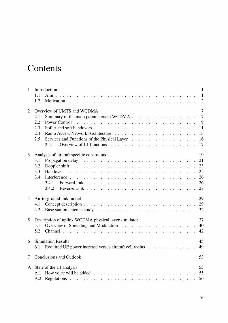
1 Introduction 11.1 Aim . . . . . . . . . . . . . . . . . . . . . . . . . . . . . . . . . . . . . . . . . 11.2 Motivation . . . . . . . . . . . . . . . . . . . . . . . . . . . . . . . . . . . . . . 2
2 Overview of UMTS and WCDMA 72.1 Summary of the main parameters in WCDMA . . . . . . . . . . . . . . . . . . . 72.2 Power Control . . . . . . . . . . . . . . . . . . . . . . . . . . . . . . . . . . . . 92.3 Softer and soft handovers . . . . . . . . . . . . . . . . . . . . . . . . . . . . . . 112.4 Radio Access Network Architecture . . . . . . . . . . . . . . . . . . . . . . . . 132.5 Services and Functions of the Physical Layer . . . . . . . . . . . . . . . . . . . 16
2.5.1 Overview of L1 functions . . . . . . . . . . . . . . . . . . . . . . . . . 17
3 Analysis of aircraft specific constraints 193.1 Propagation delay . . . . . . . . . . . . . . . . . . . . . . . . . . . . . . . . . . 213.2 Doppler shift . . . . . . . . . . . . . . . . . . . . . . . . . . . . . . . . . . . . 233.3 Handover . . . . . . . . . . . . . . . . . . . . . . . . . . . . . . . . . . . . . . 253.4 Interference . . . . . . . . . . . . . . . . . . . . . . . . . . . . . . . . . . . . . 26
3.4.1 Forward link . . . . . . . . . . . . . . . . . . . . . . . . . . . . . . . . 263.4.2 Reverse Link . . . . . . . . . . . . . . . . . . . . . . . . . . . . . . . . 27
4 Air-to-ground link model 294.1 Concept description . . . . . . . . . . . . . . . . . . . . . . . . . . . . . . . . . 294.2 Base station antenna study . . . . . . . . . . . . . . . . . . . . . . . . . . . . . 32
5 Description of uplink WCDMA physical layer simulator 375.1 Overview of Spreading and Modulation . . . . . . . . . . . . . . . . . . . . . . 405.2 Channel . . . . . . . . . . . . . . . . . . . . . . . . . . . . . . . . . . . . . . . 42
6 Simulation Results 456.1 Required UE power increase versus aircraft cell radius . . . . . . . . . . . . . . 49
7 Conclusions and Outlook 53
A State of the art analysis 55A.1 How voice will be added . . . . . . . . . . . . . . . . . . . . . . . . . . . . . . 55A.2 Regulations . . . . . . . . . . . . . . . . . . . . . . . . . . . . . . . . . . . . . 56
V
Contents
A.3 Some Players . . . . . . . . . . . . . . . . . . . . . . . . . . . . . . . . . . . . 56A.3.1 Connexion by Boeing . . . . . . . . . . . . . . . . . . . . . . . . . . . 56A.3.2 OnAir . . . . . . . . . . . . . . . . . . . . . . . . . . . . . . . . . . . . 57A.3.3 AirCell . . . . . . . . . . . . . . . . . . . . . . . . . . . . . . . . . . . 57A.3.4 Verizon AirFone . . . . . . . . . . . . . . . . . . . . . . . . . . . . . . 58
A.4 Auction News . . . . . . . . . . . . . . . . . . . . . . . . . . . . . . . . . . . . 59
B Performance of RAKE Receiver 61
C Mathematical derivations 63
Bibliography 65
VI

List of Figures
1.1 UMTS air interface architecture applied to aircraft . . . . . . . . . . . . . . . . . 11.2 Vodafone’s UMTS (red) and GSM (blue) coverage in Germany . . . . . . . . . 31.3 Maximum physical channel bit rates in UMTS with HSDPA/HSUPA . . . . . . . 5
2.1 Allocation of bandwidth in WCDMA in the time-frequency-code space . . . . . 72.2 UMTS frequency allocation in Germany . . . . . . . . . . . . . . . . . . . . . . 82.3 Closed loop Power control in WCDMA . . . . . . . . . . . . . . . . . . . . . . 102.4 Softer Handover . . . . . . . . . . . . . . . . . . . . . . . . . . . . . . . . . . . 112.5 Soft Handover . . . . . . . . . . . . . . . . . . . . . . . . . . . . . . . . . . . . 122.6 Inter-RNC soft handover . . . . . . . . . . . . . . . . . . . . . . . . . . . . . . 132.7 UMTS System Architecture . . . . . . . . . . . . . . . . . . . . . . . . . . . . 14
3.1 Illustration of airspace cell structure . . . . . . . . . . . . . . . . . . . . . . . . 193.2 Probability density function of flight path length within same cell . . . . . . . . . 203.3 Worstcase scenario . . . . . . . . . . . . . . . . . . . . . . . . . . . . . . . . . 213.4 Propagation delay definition according to 3GPP . . . . . . . . . . . . . . . . . . 223.5 PRACH propagation delay measurement report mapping . . . . . . . . . . . . . 223.6 Transmit Power Control Timing . . . . . . . . . . . . . . . . . . . . . . . . . . 233.7 Evolution of Doppler shift as aircraft flies by over base station . . . . . . . . . . 243.8 Doppler shift . . . . . . . . . . . . . . . . . . . . . . . . . . . . . . . . . . . . 243.9 Excerpt from 3GPP Iur interface specification . . . . . . . . . . . . . . . . . . . 26
4.1 Geometry involved in the terrestrial and aircraft components . . . . . . . . . . . 294.2 Typical directional pattern of a base station panel antenna for mobile communi-
cations . . . . . . . . . . . . . . . . . . . . . . . . . . . . . . . . . . . . . . . . 334.3 Interference estimation formula . . . . . . . . . . . . . . . . . . . . . . . . . . . 344.4 Interference at base station receiver as aircraft flies by for three typical antennas
(the graphs on the right are closeups) . . . . . . . . . . . . . . . . . . . . . . . 35
5.1 Description of the Simulator . . . . . . . . . . . . . . . . . . . . . . . . . . . . 385.2 Overview of Spreading . . . . . . . . . . . . . . . . . . . . . . . . . . . . . . . 41
6.1 Bit and block error rate curves for user data rate of 384 Kbps, AWGN channel . . 456.2 Bit and block error rate curves for user data rate of 12.2 Kbps, AWGN channel . 476.3 Bit and block error rate curves for user data rate of 384 Kbps, MP channel, TPC
OFF . . . . . . . . . . . . . . . . . . . . . . . . . . . . . . . . . . . . . . . . . 47
VIII
List of Figures
6.4 Bit and block error curves rate for user data rate of 384 Kbps, MP channel, TPCON . . . . . . . . . . . . . . . . . . . . . . . . . . . . . . . . . . . . . . . . . . 48
6.5 Dependency of the airspace cell size with the cost in terms of mobile terminalpower increase for AWGN channel with 0 ◦ antenna downtilt . . . . . . . . . . . 50
6.6 Dependency of the airspace cell size with the cost in terms of mobile terminalpower increase for AWGN channel with 16 ◦ antenna downtilt . . . . . . . . . . 50
6.7 Dependency of the airspace cell size with the cost in terms of mobile terminalpower increase for AWGN and MP channel (TPC) with 0 ◦ antenna downtilt . . . 51
B.1 Uncoded bit error rate check . . . . . . . . . . . . . . . . . . . . . . . . . . . . 62
C.1 Computation of fR(r) . . . . . . . . . . . . . . . . . . . . . . . . . . . . . . . . 63
IX

Abbreviations
Acronym Description3GPP 3rd Generation Partnership ProjectAWGN Additive White Gaussian NoiseBER Bit Error RateBLER Block Error RateBoD Bandwidth on DemandBPSK Binary Phase Shift KeyingBS Base StationCDMA Code Division Multiple AccessDL DownlinkDCH Dedicated ChannelDCCH Dedicated Control ChannelDPCCH Dedicated Physical Control ChannelDPDCH Dedicated Physical Data ChannelDS-CDMA Direct Spread Code Division Multiple AccessDSCH Downlink Shared ChannelDTCH Dedicated Traffic ChannelE-DCH Enhanced Uplink DCHEDGE Enhanced Data Rates for GSM EvolutionEIRP Effective Isotropic Radiated PowerFCC Federal Communication CommissionFDD Frequency Division DuplexFDMA Frequency Division Multiple AccessGGSN Gateway GPRS Source NodeGPRS General Packet Radio SystemGPS Global Positioning SystemGSM Global System for Mobile CommunicationsHSDPA High Speed Downlink Packet AccessHS-DSCH High Speed Downlink Shared ChannelHSUPA High Speed Uplink Packet AccessIP Internet ProtocolLAN Local Area NetworkMAC Medium Access ControlME Mobile EquipmentMRC Maximum Ratio Combining
XI
Abbreviations
Acronym DescriptionMS Mobile StationMSC Mobile Services Switching CentrePC Power ControlPCCC Parallel Concatenated Convolutional CoderPLMN Public Land Mobile NetworkPRACH Physical Random Access ChannelPS Packet SwitchedPSCH Physical Shared ChannelPSTN Public Switched Telephone NetworkQAM Quadrature Amplitude ModulationQoS Quality of ServiceQPSK Quadrature Phase Shift KeyingRAN Radio Access NetworkRNC Radio Network ControllerSF Spreading FactorSGSN Serving GPRS Support NodeSIR Signal to Interference RatioSNR Signal to Noise RatioTDMA Time Division Multiple AccessTPC Transmission Power ControlTTI Transmission Time IntervalUE User EquipmentUL UplinkUMTS Universal Mobile Telecommunication ServicesUTRA UMTS Terrestrial Radio AccessUTRAN UMTS Terrestrial Radio Access NetworkWCDMA Wideband CDMA, Code Division Multiple AccessWLAN Wireless Local Area Network
XII


Abbreviations
XIV
1 Introduction
1.1 Aim
The aim of this master’s thesis is to assess the suitability of UMTS for aeronautical communi-cations. Specifically, we wish to determine how existing UMTS networks may be accessed byaircraft with a direct air-to-ground communication link to provide onboard connectivity (e.g. In-ternet access).
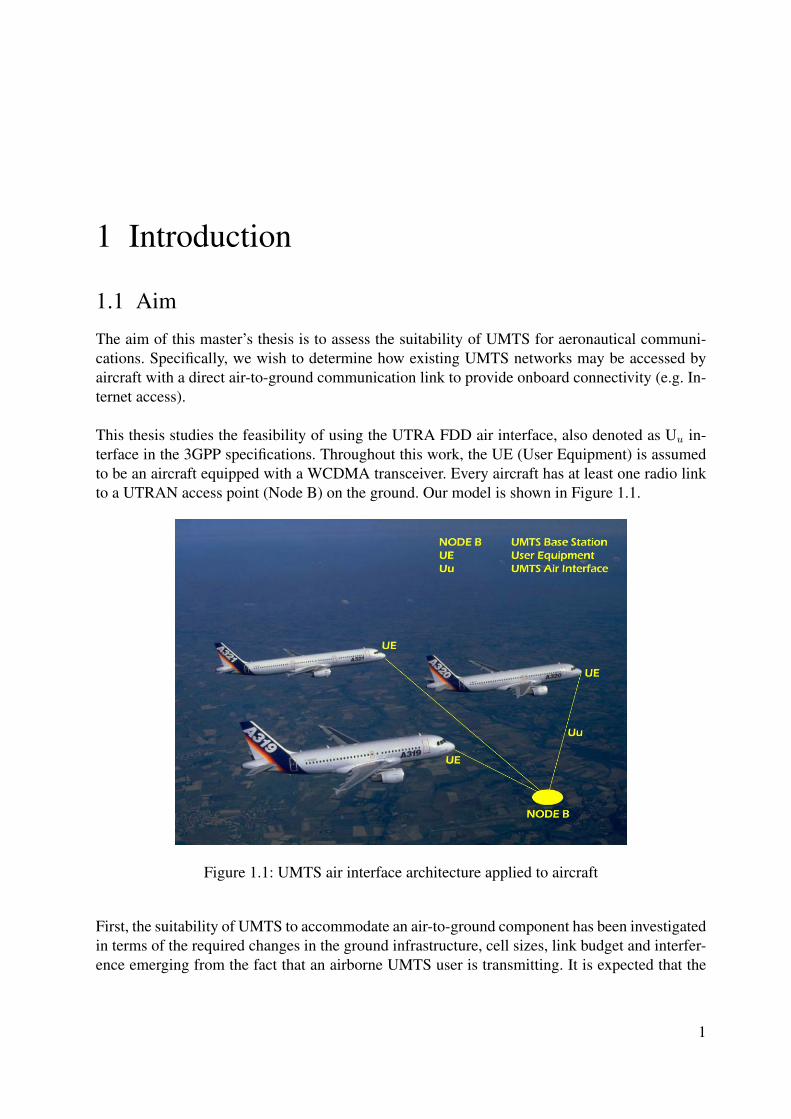
This thesis studies the feasibility of using the UTRA FDD air interface, also denoted as Uu in-terface in the 3GPP specifications. Throughout this work, the UE (User Equipment) is assumedto be an aircraft equipped with a WCDMA transceiver. Every aircraft has at least one radio linkto a UTRAN access point (Node B) on the ground. Our model is shown in Figure 1.1.
Figure 1.1: UMTS air interface architecture applied to aircraft
First, the suitability of UMTS to accommodate an air-to-ground component has been investigatedin terms of the required changes in the ground infrastructure, cell sizes, link budget and interfer-ence emerging from the fact that an airborne UMTS user is transmitting. It is expected that the
1
1 Introduction
ground infrastructure has to be adapted to the aeronautical extension by applying separate an-tennas pointing toward the sky and, thus, extending UMTS into the third dimension. Reasonablecell sizes for this extension have been defined, taking into account the mobility characteristics ofaircraft.
Second, a physical layer simulator for uplink UTRA FDD has been implemented in JAVA.The transmitter of this simulator comprises the UMTS specific channel coding, interleaving andspreading, whereas the receiver consists of the respective despreader, deinterleaver and decoder.Simulations have been performed to determine the necessary transmit power increase at a terres-trial transmitter which is required to maintain link performance in presence of aircraft generatedinterference. Using these results, the interference assessment has been identified.
1.2 Motivation
Today, aircraft seem to be the last remaining islands left for mobile communications and Internetaccess to reach. Research is going on to determine how multimedia communication services canbe provided to passengers on board in a cost-efficient fashion. Inflight internet has become a real-ity only very recently, with the emergence of the first satellite-based systems, such as "Connexionby Boeing". These systems, however, rely on expensive infrastructure (satellites), and thereforeresult inevitably in a high price for the end user.
UMTS, one of the most important third generation terrestrial mobile communication systems,is now available in many parts of Europe and the rest of the world. This, together with the factthat many short range aircraft fly mainly over landmasses, where one or more public land mobilenetworks are in operation on the ground, motivates this investigation to find out how, if possible,aircraft could be interfaced into the ground infrastructure as if they were flying mobile nodes,reusing as much as possible existing technology (both hardware and software).
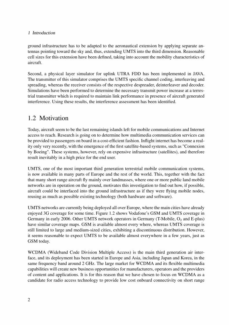
UMTS networks are currently being deployed all over Europe, where the main cities have alreadyenjoyed 3G coverage for some time. Figure 1.2 shows Vodafone’s GSM and UMTS coverage inGermany in early 2006. Other UMTS network operators in Germany (T-Mobile, O2 and E-plus)have similar coverage maps. GSM is available almost every where, whereas UMTS coverage isstill limited to large and medium-sized cities, exhibiting a discontinuous distribution. However,it seems reasonable to expect UMTS to be available almost everywhere in a few years, just asGSM today.
WCDMA (Wideband Code Division Multiple Access) is the main third generation air inter-face, and its deployment has been started in Europe and Asia, including Japan and Korea, in thesame frequency band around 2 GHz. The large market for WCDMA and its flexible multimediacapabilities will create new business opportunities for manufacturers, operators and the providersof content and applications. It is for this reason that we have chosen to focus on WCDMA as acandidate for radio access technology to provide low cost onboard connectivity on short range
2
1.2 Motivation
Figure 1.2: Vodafone’s UMTS (red) and GSM (blue) coverage in Germany
flights with a direct air-to-ground communication link.
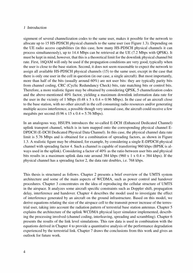
Another reason for choosing UMTS as a candidate for a direct air-to-ground link can be seenby considering the data rates that this technology can offer. In general, an aircraft will have afairly high demand in terms of data rate, since several passengers may be using the common air-to-ground link simultaneously. Second generation systems, like GSM, were originally designedfor efficient delivery of voice services. UMTS networks are, on the contrary, designed from thebeginning for flexible delivery of any type of service.The current 3GPP specification (release 7) contains, among others, two significant extensionsto the original 1999 release, which are known in the telecom industry as HSDPA (High SpeedDownlink Packet Access) and HSUPA (High Speed Uplink Packet Access). HSDPA consistsbasically in introducing a new downlink transport channel known as HS-DSCH (High SpeedDownlink Shared Channel) which is mapped onto the physical channel HS-PDSCH (HS-DSCHPhysical Downlink Shared Channel), capable of transferring 960,000 physical (coded) bits persecond (this is with 16QAM; if QPSK is used instead, 480,000 bps). Multicoding, that is, as-
3
1 Introduction
signment of several channelization codes to the same user, makes it possible for the network toallocate up to 15 HS-PDSCH physical channels to the same user (see Figure 1.3). Depending onthe UE radio access capabilities (in this case, how many HS-PDSCH physical channels it canprocess simultaneously), up to 14.4 Mbps can be retrieved at the UE (7.2 Mbps with QPSK). Itmust be kept in mind, however, that this is a theoretical limit for the downlink physical channel bitrate. First, 16QAM will only be used if the propagation conditions are very good, typically whenthe user is close to the base station. Second, it does not seem reasonable to expect the network toassign all available HS-PDSCH physical channels (15) to the same user, except in the case thatthere is only one user in the cell in question (in our case, a single aircraft). But most importantly,more than half of the bits (usually around 60%) are not user bits: they are typically parity bitsfrom channel coding, CRC (Cyclic Redundancy Check) bits, rate matching bits or control bits.Therefore, a more realistic figure may be obtained by considering QPSK, 5 channelization codesand the above-mentioned 40% factor, yielding a maximum downlink information data rate forthe user in the vicinity of 1 Mbps (0.48 x 5 x 0.4 = 0.96 Mbps). In the case of an aircraft closeto the base station, with no other aircraft in the cell consuming radio resources and/or generatingmultiple access interference, a possible though very unusual case, the aircraft could receive a fewmegabits per second (0.96 x 15 x 0.4 = 5.76 Mbps).
In an analogous way, HSUPA introduces the so-called E-DCH (Enhanced Dedicated Channel)uplink transport channel, which is in turn mapped onto the corresponding physical channel E-DPDCH (E-DCH Dedicated Physical Data Channel). In this case, the physical channel data ratelimit is 5.76 Mbps and is obtained for a combination of spreading factors, as shown in Figure1.3. A realistic figure may be obtained, for example, by considering a single E-DPDCH physicalchannel with spreading factor 4. Such a channel is capable of transferring 960 kbps (BPSK is al-ways used in the uplink). Considering a factor of 40% as the ratio between user bits and physicalbits results in a maximum uplink data rate around 384 kbps (960 x 1 x 0.4 = 384 kbps). If thephysical channel has a spreading factor 2, the data rate doubles, i.e. 768 kbps.
This thesis is structured as follows. Chapter 2 presents a brief overview of the UMTS systemarchitecture and some of the main aspects of WCDMA, such as power control and handoverprocedures. Chapter 3 concentrates on the idea of reproducing the cellular structure of UMTSin the airspace. It analyzes some aircraft specific constraints such as Doppler shift, propagationdelay, interference and handover. Chapter 4 describes the model used to investigate the effectof interference generated by an aircraft on the ground infrastructure. Based on this model, wederive equations relating the size of the airspace cell to the transmit power increase of the terres-trial user, taking into account the radiation pattern of terrestrial base station antennas. Chapter 5explains the architecture of the uplink WCDMA physical layer simulator implemented, describ-ing the processing involved (channel coding, interleaving, spreading and scrambling). Chapter 6presents the results of the link level simulations. This raw data is used in combination with theequations derived in Chapter 4 to provide a quantitative analysis of the performance degradationexperienced by the terrestrial link. Chapter 7 draws the conclusions from this work and gives anoutlook for future work.
4
1.2 Motivation
Figure 1.3: Maximum physical channel bit rates in UMTS with HSDPA/HSUPA
5

1 Introduction
6
2 Overview of UMTS and WCDMA
This chapter presents a brief overview of UMTS and explains the main system design parametersrelated to the WCDMA air interface.
2.1 Summary of the main parameters in WCDMA
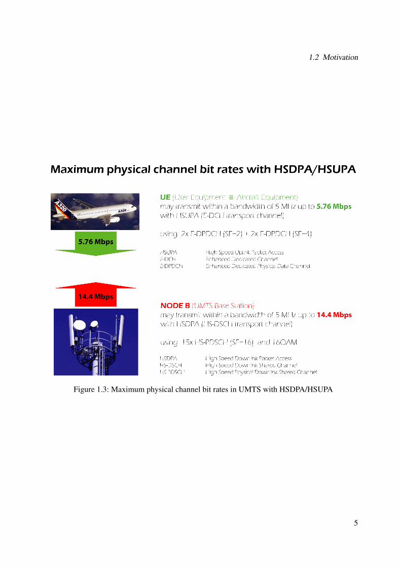
WCDMA is a Wideband Direct-Sequence Code Division Multiple Access (DS-CDMA) system,i.e. user information bits are spread over a wide bandwidth by multiplying the user data withquasi-random bits (called chips) derived from CDMA spreading codes. In order to support veryhigh bit rates (up to 2 Mbps), the use of variable spreading factors and multicode connections issupported.
Figure 2.1: Allocation of bandwidth in WCDMA in the time-frequency-code space
As shown in Figure 2.1, the chip rate of 3.84 Mcps leads to a carrier bandwidth of approximately5 MHz. DS-CDMA systems with a bandwidth of about 1 MHz, such as IS-95 are commonlyreferred to as narrowband CDMA systems. The inherently wide carrier bandwidth of WCDMAsupports high user data rates and also certain performance benefits, such as increased multipathdiversity. Subject to his operating license, the network operator can deploy multiple 5 MHz car-riers to increase capacity, possibly in the form of hierarchical cell layers. Figure 2.2 shows the
7
2 Overview of UMTS and WCDMA
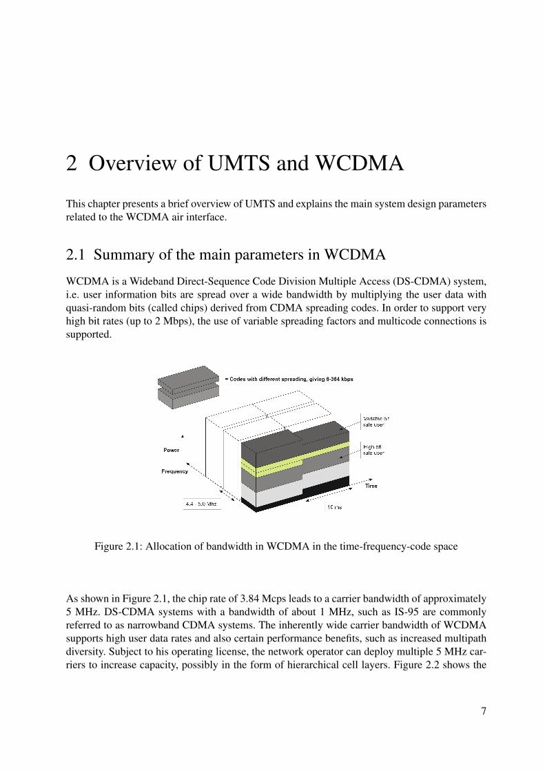
UMTS spectrum in Germany. Currently, there are four network operators providing UMTS ser-vices in FDD mode (T-Mobile, Vodafone, O2 and E-Plus), each with a paired 10-MHz band, i.e.two channels.
Figure 2.2: UMTS frequency allocation in Germany
WCDMA also supports highly variable user data rates, in other words, the concept of obtain-ing Bandwidth on Demand (BoD) is well supported. The user data rate is kept constant duringeach 10 ms frame. However, the data capacity among the users can change from frame to frame.This fast radio capacity allocation will typically be controlled by the network to achieve optimumthroughput for packet data services.
WCDMA supports two basic modes of operation: Frequency Division Duplex (FDD) and TimeDivision Duplex (TDD). In the FDD mode, separate 5 MHz carrier frequencies are used for theuplink and downlink respectively, whereas in the TDD only one 5 MHz is time shared betweenthe uplink and the downlink.
WCDMA supports the operation of asynchronous base stations, so that, unlike in the synchronousIS-95 system, there is no need for a global time reference such as GPS. It also employs coher-ent detection on uplink and downlink based on the use of pilot symbols or common pilot. TheWCDMA air interface has been crafted in such a way that advanced CDMA receiver concepts,such as multiuser detection and smart adaptive antennas, can be deployed by the network opera-tor as a system option to increase capacity and or coverage. WCDMA is developed in conjunctionwith GSM. Therefore, handovers between GSM and WCDMA are supported in order to be ableto leverage the GSM coverage for the introduction of WCDMA. The following sections explain
8
2.2 Power Control
some important phenomena of UTRA.
2.2 Power Control
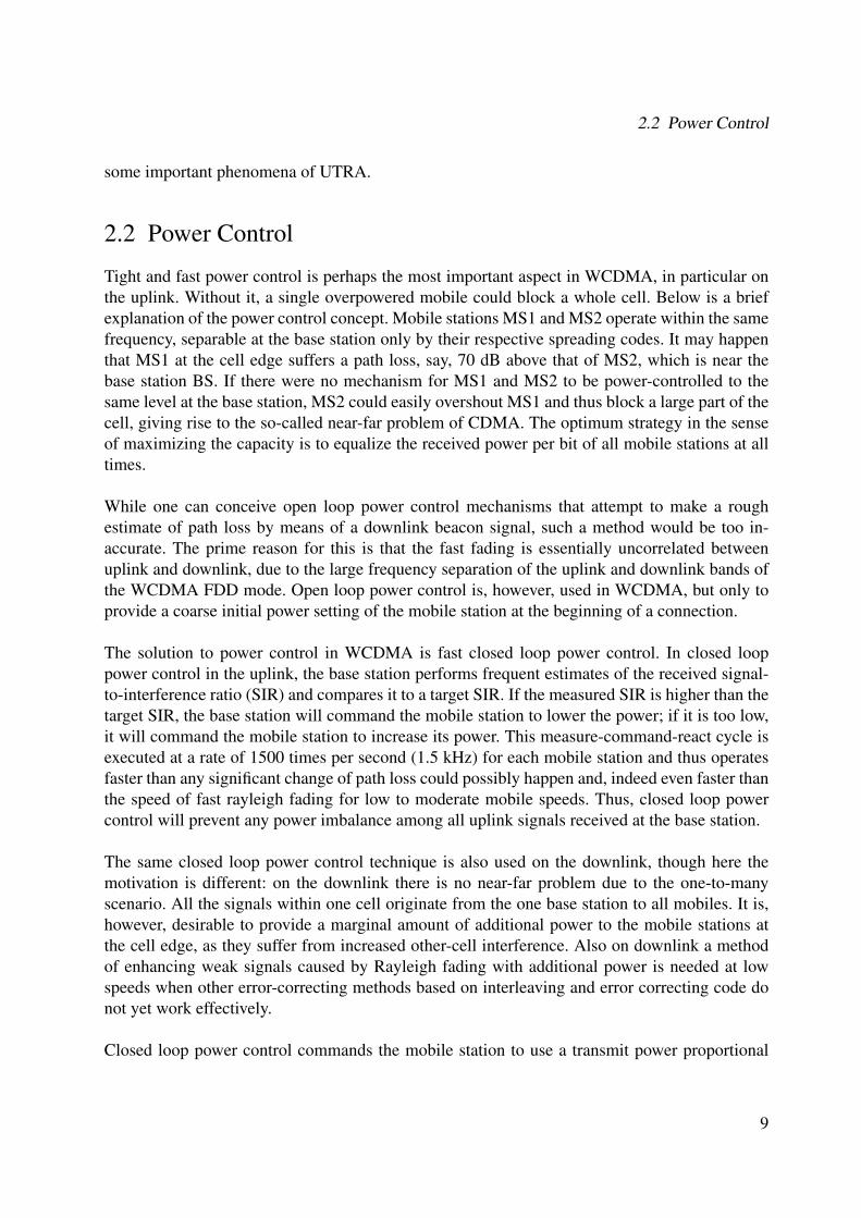
Tight and fast power control is perhaps the most important aspect in WCDMA, in particular onthe uplink. Without it, a single overpowered mobile could block a whole cell. Below is a briefexplanation of the power control concept. Mobile stations MS1 and MS2 operate within the samefrequency, separable at the base station only by their respective spreading codes. It may happenthat MS1 at the cell edge suffers a path loss, say, 70 dB above that of MS2, which is near thebase station BS. If there were no mechanism for MS1 and MS2 to be power-controlled to thesame level at the base station, MS2 could easily overshout MS1 and thus block a large part of thecell, giving rise to the so-called near-far problem of CDMA. The optimum strategy in the senseof maximizing the capacity is to equalize the received power per bit of all mobile stations at alltimes.
While one can conceive open loop power control mechanisms that attempt to make a roughestimate of path loss by means of a downlink beacon signal, such a method would be too in-accurate. The prime reason for this is that the fast fading is essentially uncorrelated betweenuplink and downlink, due to the large frequency separation of the uplink and downlink bands ofthe WCDMA FDD mode. Open loop power control is, however, used in WCDMA, but only toprovide a coarse initial power setting of the mobile station at the beginning of a connection.
The solution to power control in WCDMA is fast closed loop power control. In closed looppower control in the uplink, the base station performs frequent estimates of the received signal-to-interference ratio (SIR) and compares it to a target SIR. If the measured SIR is higher than thetarget SIR, the base station will command the mobile station to lower the power; if it is too low,it will command the mobile station to increase its power. This measure-command-react cycle isexecuted at a rate of 1500 times per second (1.5 kHz) for each mobile station and thus operatesfaster than any significant change of path loss could possibly happen and, indeed even faster thanthe speed of fast rayleigh fading for low to moderate mobile speeds. Thus, closed loop powercontrol will prevent any power imbalance among all uplink signals received at the base station.
The same closed loop power control technique is also used on the downlink, though here themotivation is different: on the downlink there is no near-far problem due to the one-to-manyscenario. All the signals within one cell originate from the one base station to all mobiles. It is,however, desirable to provide a marginal amount of additional power to the mobile stations atthe cell edge, as they suffer from increased other-cell interference. Also on downlink a methodof enhancing weak signals caused by Rayleigh fading with additional power is needed at lowspeeds when other error-correcting methods based on interleaving and error correcting code donot yet work effectively.
Closed loop power control commands the mobile station to use a transmit power proportional
9
2 Overview of UMTS and WCDMA
to the inverse of the received power (or SIR). Figure 2.3 illustrates the concept of closed looppower control in UMTS. Provided the mobile stations have enough head room to ramp the powerup, only very little residual fading is left and the channel becomes an essentially non-fading chan-nel as seen from the base station receiver. While this fading removal is highly desirable from thereceiver point of view, it comes out at the expense of increased average transmit power at thetransmitting end. This means that a mobile station in a deep fade, i.e. using a large transmissionpower, will cause increased interference to other cells.
Figure 2.3: Closed loop Power control in WCDMA
Before leaving the area of closed loop power control, attention is drawn toward one more re-lated control loop connected with it: outer loop power control. Outer loop power control adjuststhe target SIR setpoint in the base station according to the needs of the individual radio link andaims at a constant quality, usually defined as a certain target bit error rate (BER) or block errorrate (BLER), which depends on the mobile speed and the multipath profile. Now, if one wereto set the target SIR setpoint for the worst case, i.e. high mobile speeds, one would waste muchcapacity for those connections at low speeds. Thus, the best strategy is to let the target SIR set-point float around the minimum value that just fulfills the required target quality. The target SIRsetpoint will change over time.
Outer loop control is typically implemented by having the base station tag each uplink user datawith a frame reliability indicator, such as a CRC check result obtained during the decoding ofthat particular user data frame. Should the frame quality indicator indicate to the Radio NetworkController (RNC) that the transmission quality is decreasing, the RNC in turn will command thebase station to increase the target SIR setpoint by a certain amount. The reason for having outer
10
2.3 Softer and soft handovers
loop control reside in the RNC is that this function should be performed after a possible softhandover combining.
2.3 Softer and soft handovers
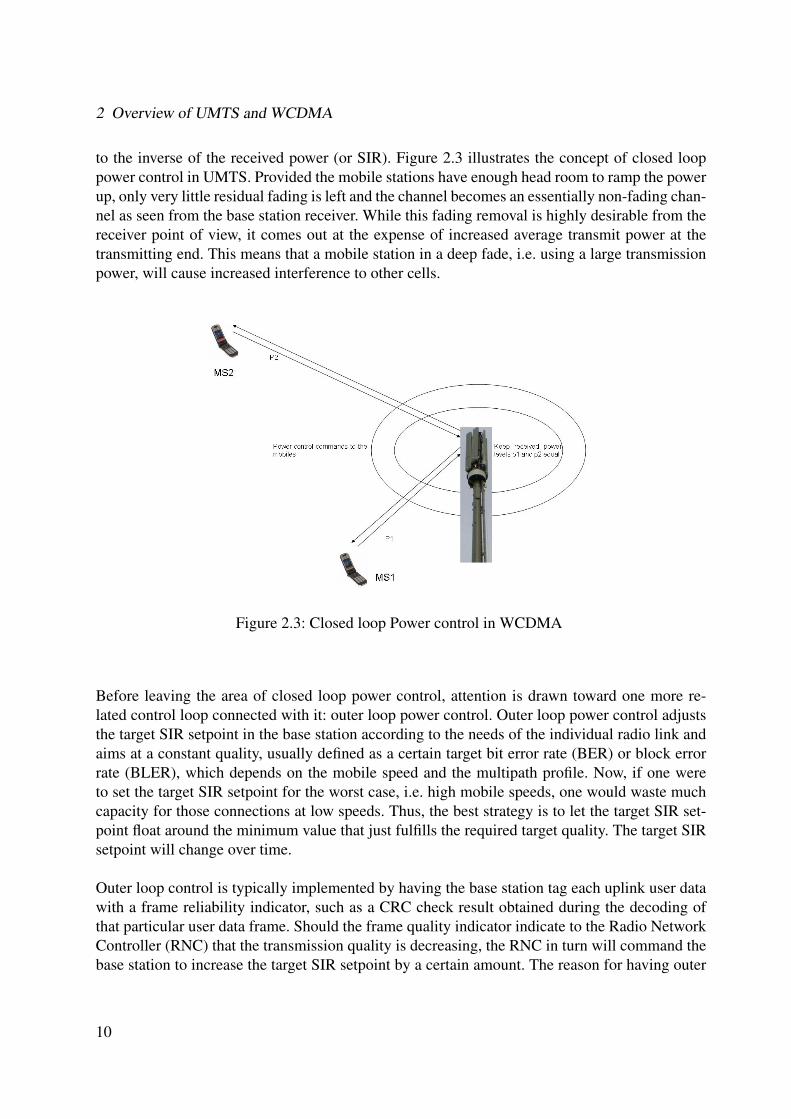
During softer handover, a mobile station is in the overlapping cell coverage area of two adjacentsectors of a base station. The communication between mobile station and base station take placeconcurrently via two air interface channels, one for each sector separately. This requires the useof two separate codes in the downlink direction, so that the mobile station can distinguish thesignals. The two signals are received in the mobile station by means of rake processing, verysimilar to multipath reception, except that the fingers need to generate the respective code foreach sector for the appropriate despreading operation. Figure 2.4 shows the softer handover sce-nario.
Figure 2.4: Softer Handover
In the uplink direction, a similar process takes place at the base station: the code channel ofthe mobile station is received in each sector, then routed to the same baseband rake receiverand the maximal ratio combined there in the usual way. During softer handover, only one powercontrol loop per connection is active. Softer handover typically occurs in about 5-15 % of con-nections.
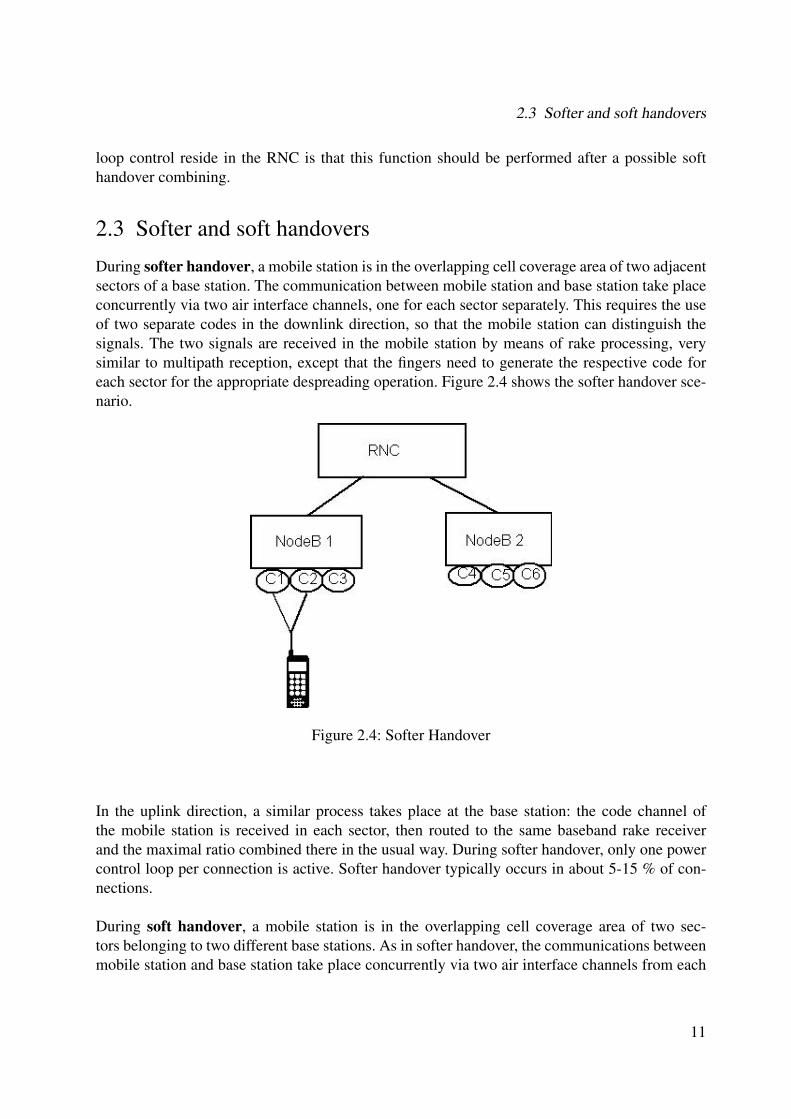
During soft handover, a mobile station is in the overlapping cell coverage area of two sec-tors belonging to two different base stations. As in softer handover, the communications betweenmobile station and base station take place concurrently via two air interface channels from each
11
2 Overview of UMTS and WCDMA
base station separately. As in softer handover, both channels (signals) are received at the mobilestation by maximal ratio combining rake processing. Seen from the mobile, there are very fewdifferences between softer and soft handover.
Figure 2.5: Soft Handover
However, in the uplink direction, soft handover differs significantly from softer handover: thecode channel of the mobile station is received from both base stations, but the received data isthen routed to the RNC for combining. This is typically done so that the same frame reliabilityindicator as provided for outer loop power control is used to select the better frame between thetwo possible candidates within the RNC. This selection takes place after each interleaving pe-riod, i.e. every 10-80 ms. Figure 2.5 shows the soft handover scenario.
During soft handover, two power control loops per connection are active, one for each basestation. Soft handover occurs in 20-40 % of connections. To cater for soft handover connections,the following additional resources need to be provided by the system and must be considered inthe planning phase:
• Additional rake receiver channels in the base stations.
• Additional transmission links between base stations and RNC.
• Additional rake fingers in the mobile stations.
We can also find that in UMTS soft and softer handover can take place in combination with eachother. It is same as softer handover but in this case the cells belong to more than one nodeB andthe combining is then done at the RNC. In general it is possible to have softer and soft handovers
12
2.4 Radio Access Network Architecture
simultaneously.
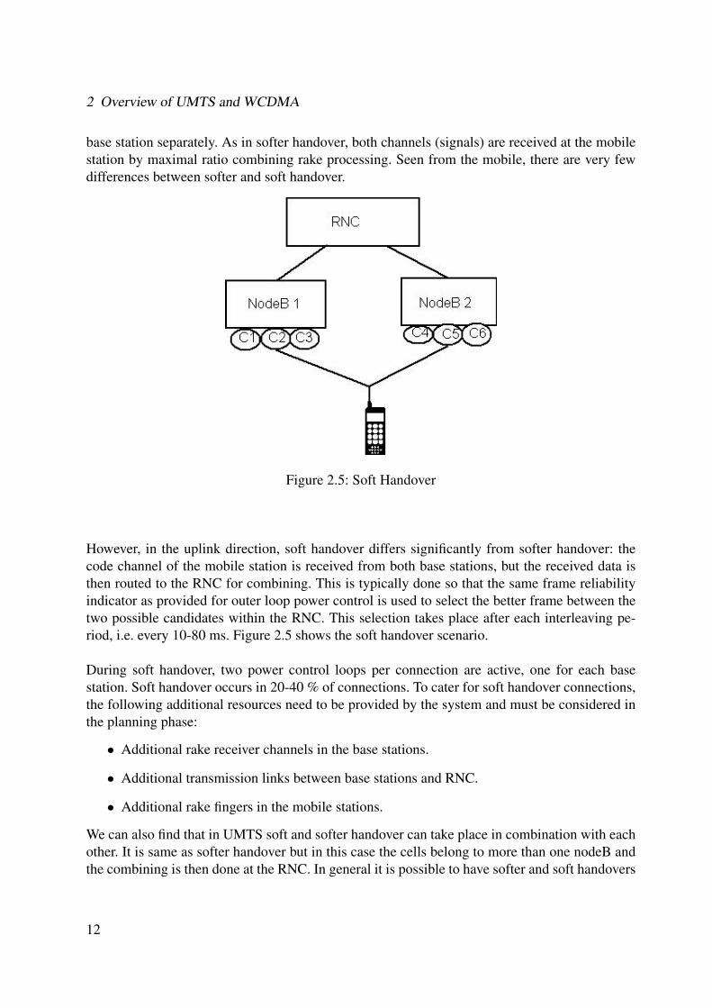
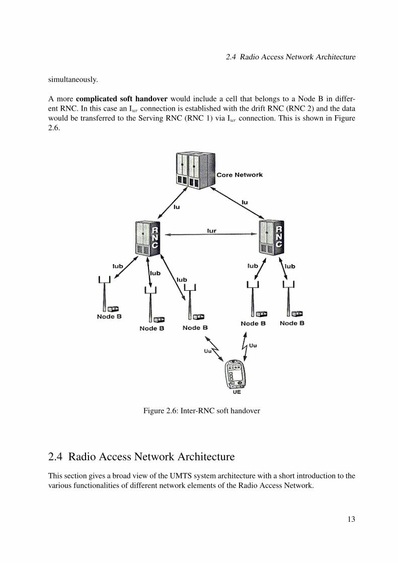
A more complicated soft handover would include a cell that belongs to a Node B in differ-ent RNC. In this case an Iur connection is established with the drift RNC (RNC 2) and the datawould be transferred to the Serving RNC (RNC 1) via Iur connection. This is shown in Figure2.6.
Figure 2.6: Inter-RNC soft handover
2.4 Radio Access Network Architecture
This section gives a broad view of the UMTS system architecture with a short introduction to thevarious functionalities of different network elements of the Radio Access Network.
13
2 Overview of UMTS and WCDMA
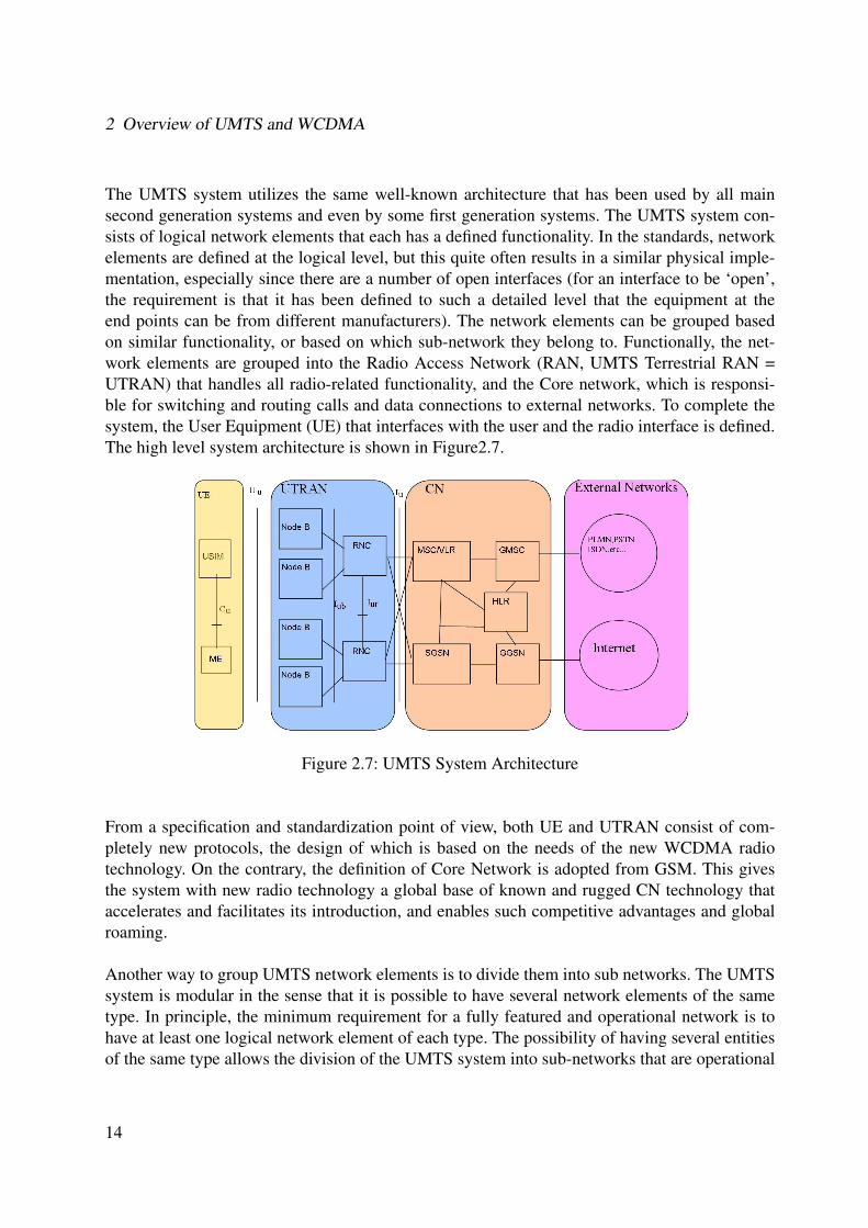
The UMTS system utilizes the same well-known architecture that has been used by all mainsecond generation systems and even by some first generation systems. The UMTS system con-sists of logical network elements that each has a defined functionality. In the standards, networkelements are defined at the logical level, but this quite often results in a similar physical imple-mentation, especially since there are a number of open interfaces (for an interface to be ‘open’,the requirement is that it has been defined to such a detailed level that the equipment at theend points can be from different manufacturers). The network elements can be grouped basedon similar functionality, or based on which sub-network they belong to. Functionally, the net-work elements are grouped into the Radio Access Network (RAN, UMTS Terrestrial RAN =UTRAN) that handles all radio-related functionality, and the Core network, which is responsi-ble for switching and routing calls and data connections to external networks. To complete thesystem, the User Equipment (UE) that interfaces with the user and the radio interface is defined.The high level system architecture is shown in Figure2.7.
Figure 2.7: UMTS System Architecture
From a specification and standardization point of view, both UE and UTRAN consist of com-pletely new protocols, the design of which is based on the needs of the new WCDMA radiotechnology. On the contrary, the definition of Core Network is adopted from GSM. This givesthe system with new radio technology a global base of known and rugged CN technology thataccelerates and facilitates its introduction, and enables such competitive advantages and globalroaming.
Another way to group UMTS network elements is to divide them into sub networks. The UMTSsystem is modular in the sense that it is possible to have several network elements of the sametype. In principle, the minimum requirement for a fully featured and operational network is tohave at least one logical network element of each type. The possibility of having several entitiesof the same type allows the division of the UMTS system into sub-networks that are operational
14

2.4 Radio Access Network Architecture
either on their own or together with other sub networks and that they are distinguished from eachother with unique identities. Such a sub network is called UMTS PLMN (Public Land MobileNetwork), typically one PLMN is operated by a single operator and is connected other PLMN aswell as to other types of network, such as ISDN, PSTN, the internet and so on. Figure2.7 showselements in a PLMN and in order to illustrate the connections, shows also connections to externalnetworks.
A short introduction to all the elements is given below.
The UE consists of two parts:The Mobile Equipment (ME) is the radio terminal used for radio communication over the Uu
interface.The UMTS Subscriber Identity Module (USIM) is a smartcard that holds the subscriber identity,performs authentication algorithms and stores authentication and encryption keys and some sub-scription information that is needed at the terminal.
UTRAN also consists of two distinct elements:The Node B converts the data flow between the Iub and Uu interfaces. It also participates in radioresource management.The Radio Network Controller (RNC) owns and controls the radio resources in its domain (theNode B’s connected to it). RNC is the service access point for all its services UTRAN providesthe CN, for example, management of connections to the UE.
The main elements of the GSM CN are as follows:HLR (Home Location Register) is a database located in the user’s home system that stores themaster copy of the user’s service profile. The service profile consists of, for example, informa-tion on allowed services, forbidden roaming areas, and supplementary service information suchas status of call forwarding and the call forwarding number. It is created when a new user sub-scribes to the system and remains stored as long as the subscription is active. For the purposeof routing incoming transaction to the UE (calls or short messages), the HLR also stores the UElocation on the level of MSC/VLR and/or SGSN, i.e. on the level of the serving system.
MSC/VLR (Mobile Services Switching Center/Visitor Location Register) is the switch (MSC)and database (VLR) that serves the UE in its current location for Circuit Switched (CS) services.The MSC function is used to switch the CS transactions, and the VLR function holds a copy ofthe visiting user’s service profile, as well as more precise information on the UE’s location withinthe serving system. The part of the network that is accessed via the MSC/VLR is often referredto the CS domain. MSC also has a role in the early UE handling.
GMSC (Gate way MSC) is the switch at the point where UMTS PLMN is connected to exter-nal CS networks. All incoming and outgoing CS connections go through GMSC. SGSN (ServingGPRS Support Node) functionality is similar to that of MSC/VLR but is typically used for packetswitched (PS) services. The part of the network that is accessed via the SGSN is often referred to
15
2 Overview of UMTS and WCDMA
as the PS domain. Similar to MSC, SGSN support is needed for the early UE handling operation.GGSN (Gateway GPRS Support Node ) has functionality that is close to that of GMSC but is inrelation to PS services.
The external networks can be divided into two groups:CS Networks: These provide circuit switched connections, like existing telephony service. ISDNand PSTN are examples of CS networks.PS networks: These provide connections for packet data services. The internet is one example ofa PS network.
The UMTS standards are structured so that internal functionality of the network elements isnot specified in detail. Instead, the interfaces between logical network elements have been de-fined. The following main open interfaces are specified:
Cu Interface: This is the electrical interface between the USIM smartcard and the ME. The inter-face follows a standard format for smartcards.Uu Interface: This is the WCDMA radio interface. The Uu interface through which the UE ac-cesses the fixed point point of the system and is probably the most important open interface inUMTS. There are likely to be many more UE manufacturers than manufacturers of fixed net-works elements.Iu Interface: This connects UTRAN to CN. Similarly, to the corresponding interfaces in GSM, a(Circuit Switched ) and Gb (Packet Switched ), the open Iu interface gives UMTS operators thepossibility of acquiring UTRAN and CN from different manufacturers. The enabled competitionin this area has been one of the success factors of GSM.Iur Interface: This is the open interface that allows soft handover between RNC’s from differentmanufacturers and therefore complements the open Iu interface.Iub Interface: The Iub connects a Node B and an RNC. UMTS is the first commercial mobiletelephony system where the controller base station interface is standardized as a fully open inter-face. Like the other open interfaces, open Iub is expected to further motivate competition betweenmanufacturers in this area. It is likely that the new manufacturers concentrating exclusively onNode B’s will enter the market.
2.5 Services and Functions of the Physical Layer
The Physical Layer (Layer 1) is the lowest layer in the Open System Interconnection (OSI) Ref-erence Model and it supports all functions required for the transmission of bit streams on thephysical medium.The physical layer offers data transport services to higher layers. The access tothese services is through the use of transport channels via the MAC (Medium Access Control)sub layer. The characteristics of a transport channel are defined by its transport format (or formatset), specifying the physical layer processing to be applied to the transport channel in question,such as convolutional channel coding and interleaving and any service specific rate matching asneeded.
16
2.5 Services and Functions of the Physical Layer
The physical layer operates exactly according to the L1 radio frame timing. A transport block isdefined as the data accepted by the physical layer to be jointly CRC protected. The transmissionblock timing is then tied exactly to the TTI timing, e.g. every transmission block is generatedprecisely every TTI.
A UE can set up multiple transport channels simultaneously, each having own transport char-acteristics (e.g.offering different error correction capability). Each transport channel can be usedfor information stream transfer of one radio bearer or for layer 2 and higher layer signallingmessages. The multiplexing of transport channels onto the same or different physical channels iscarried out by L1.
2.5.1 Overview of L1 functions
The Physical layer performs the following main functions:
• FEC encoding/decoding of transport channels
• Measurements and indication to higher layers (e.g. FER, SIR, interference power, trans-mission power, etc...)
• Macro diversity distribution/combining and soft handover execution.
• Error detection on transport channels.
• Multiplexing of transport channels and demultiplexing of coded composite transport chan-nels.
• Rate Matching
• Mapping coded composite transport channels on physical channels.
• Modulation and spreading/demodulation and despreading of physical channels.
• Frequency and time (chip, bit, slot, frame) synchronisation.
• Closed-loop power control.
• Power weighting and combining of physical channels.
• RF processing.
• Support of uplink synchronisation (TDD only)
• Timing advance on uplink channels (TDD only)
17
2 Overview of UMTS and WCDMA
18
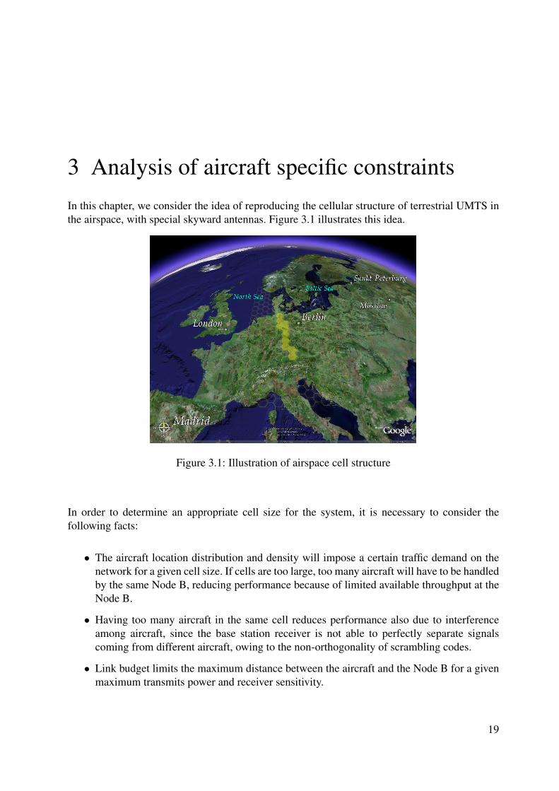
3 Analysis of aircraft specific constraintsIn this chapter, we consider the idea of reproducing the cellular structure of terrestrial UMTS inthe airspace, with special skyward antennas. Figure 3.1 illustrates this idea.
Figure 3.1: Illustration of airspace cell structure
In order to determine an appropriate cell size for the system, it is necessary to consider thefollowing facts:
• The aircraft location distribution and density will impose a certain traffic demand on thenetwork for a given cell size. If cells are too large, too many aircraft will have to be handledby the same Node B, reducing performance because of limited available throughput at theNode B.
• Having too many aircraft in the same cell reduces performance also due to interferenceamong aircraft, since the base station receiver is not able to perfectly separate signalscoming from different aircraft, owing to the non-orthogonality of scrambling codes.
• Link budget limits the maximum distance between the aircraft and the Node B for a givenmaximum transmits power and receiver sensitivity.
19
3 Analysis of aircraft specific constraints
• Existing terrestrial base station antennas typically have some skyward side lobes. If aircrafttransmit at the same frequencies as mobile terminals on the ground, the performance of theterrestrial network in the uplink will be degraded. If aircraft cells are too large, the transmitpower at the aircraft will necessarily be very high, making this degradation intolerable.
• Aircraft flight speed is relatively high (around 900 km/h, or 15 km/min). If cells are toosmall, handovers will occur too often.
• The idea is to cover a reasonably large area (Europe) while minimizing deployment costs.If cells are too small, many base stations will be required, making the system economicallyunviable.
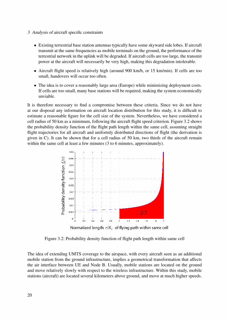
It is therefore necessary to find a compromise between these criteria. Since we do not haveat our disposal any information on aircraft location distribution for this study, it is difficult toestimate a reasonable figure for the cell size of the system. Nevertheless, we have considered acell radius of 50 km as a minimum, following the aircraft flight speed criterion. Figure 3.2 showsthe probability density function of the flight path length within the same cell, assuming straightflight trajectories for all aircraft and uniformly distributed directions of flight (the derivation isgiven in C). It can be shown that for a cell radius of 50 km, two thirds of the aircraft remainwithin the same cell at least a few minutes (3 to 6 minutes, approximately).
Figure 3.2: Probability density function of flight path length within same cell
The idea of extending UMTS coverage to the airspace, with every aircraft seen as an additionalmobile station from the ground infrastructure, implies a geometrical transformation that affectsthe air interface between UE and Node B. Usually, mobile stations are located on the groundand move relatively slowly with respect to the wireless infrastructure. Within this study, mobilestations (aircraft) are located several kilometers above ground, and move at much higher speeds.
20
3.1 Propagation delay
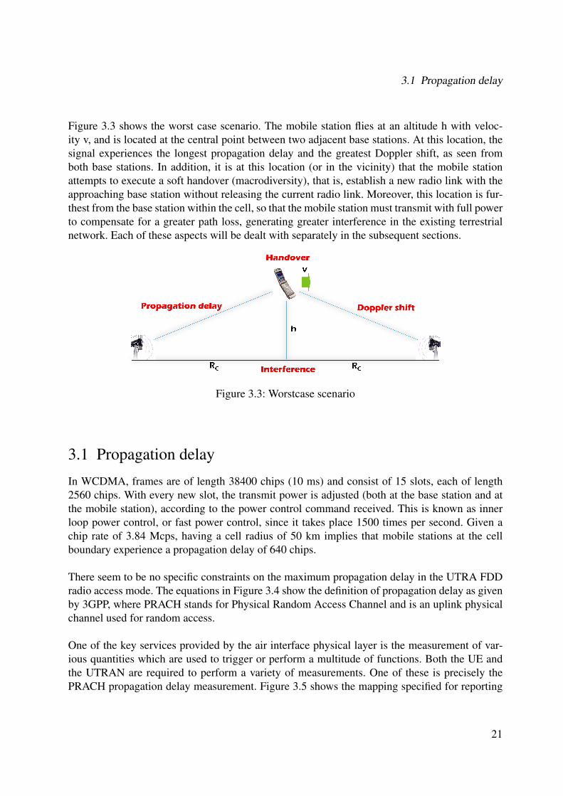
Figure 3.3 shows the worst case scenario. The mobile station flies at an altitude h with veloc-ity v, and is located at the central point between two adjacent base stations. At this location, thesignal experiences the longest propagation delay and the greatest Doppler shift, as seen fromboth base stations. In addition, it is at this location (or in the vicinity) that the mobile stationattempts to execute a soft handover (macrodiversity), that is, establish a new radio link with theapproaching base station without releasing the current radio link. Moreover, this location is fur-thest from the base station within the cell, so that the mobile station must transmit with full powerto compensate for a greater path loss, generating greater interference in the existing terrestrialnetwork. Each of these aspects will be dealt with separately in the subsequent sections.
Figure 3.3: Worstcase scenario
3.1 Propagation delay
In WCDMA, frames are of length 38400 chips (10 ms) and consist of 15 slots, each of length2560 chips. With every new slot, the transmit power is adjusted (both at the base station and atthe mobile station), according to the power control command received. This is known as innerloop power control, or fast power control, since it takes place 1500 times per second. Given achip rate of 3.84 Mcps, having a cell radius of 50 km implies that mobile stations at the cellboundary experience a propagation delay of 640 chips.
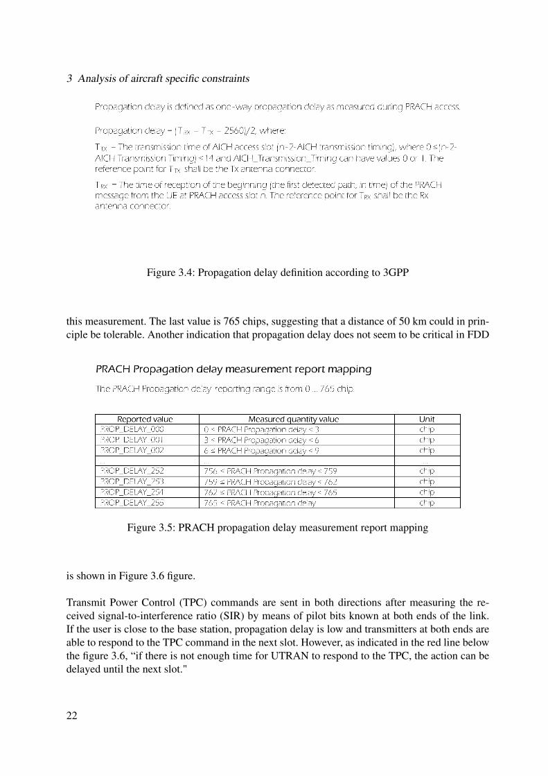
There seem to be no specific constraints on the maximum propagation delay in the UTRA FDDradio access mode. The equations in Figure 3.4 show the definition of propagation delay as givenby 3GPP, where PRACH stands for Physical Random Access Channel and is an uplink physicalchannel used for random access.
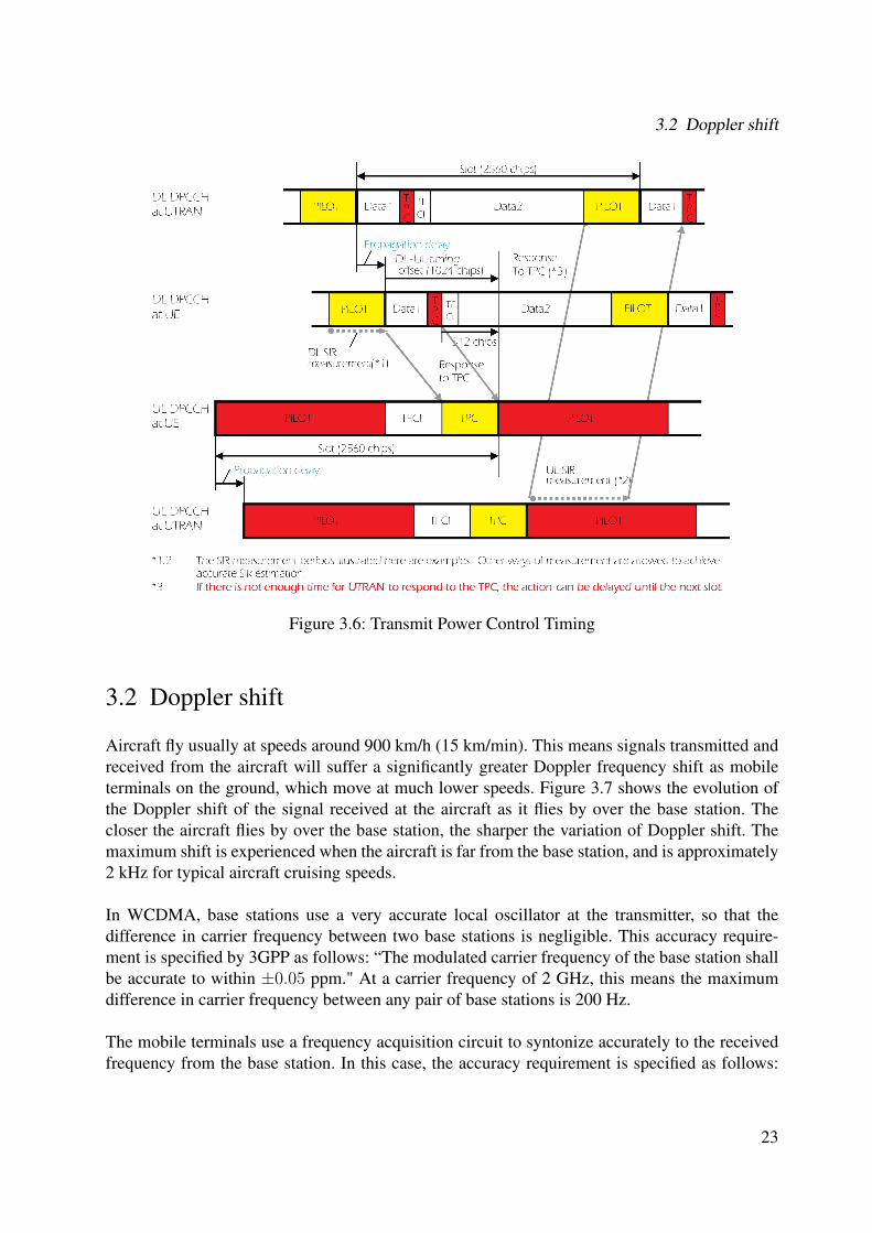
One of the key services provided by the air interface physical layer is the measurement of var-ious quantities which are used to trigger or perform a multitude of functions. Both the UE andthe UTRAN are required to perform a variety of measurements. One of these is precisely thePRACH propagation delay measurement. Figure 3.5 shows the mapping specified for reporting
21
3 Analysis of aircraft specific constraints
Figure 3.4: Propagation delay definition according to 3GPP
this measurement. The last value is 765 chips, suggesting that a distance of 50 km could in prin-ciple be tolerable. Another indication that propagation delay does not seem to be critical in FDD
Figure 3.5: PRACH propagation delay measurement report mapping
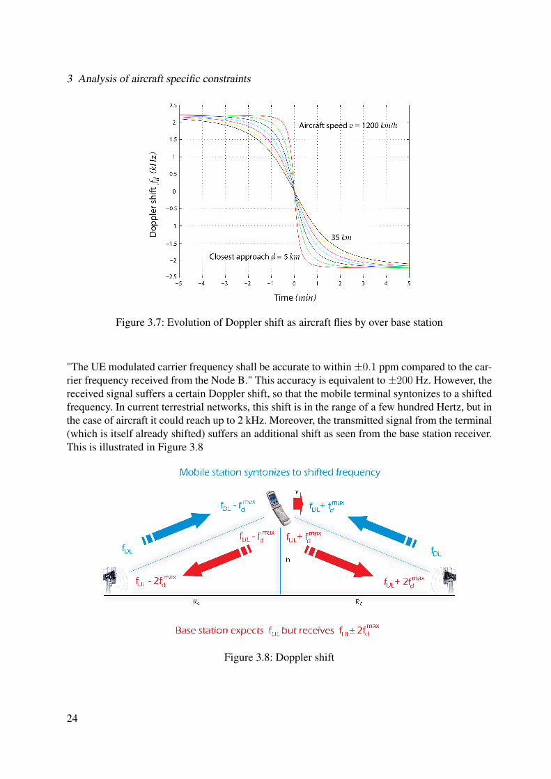
is shown in Figure 3.6 figure.
Transmit Power Control (TPC) commands are sent in both directions after measuring the re-ceived signal-to-interference ratio (SIR) by means of pilot bits known at both ends of the link.If the user is close to the base station, propagation delay is low and transmitters at both ends areable to respond to the TPC command in the next slot. However, as indicated in the red line belowthe figure 3.6, “if there is not enough time for UTRAN to respond to the TPC, the action can bedelayed until the next slot."
22
3.2 Doppler shift
Figure 3.6: Transmit Power Control Timing
3.2 Doppler shift
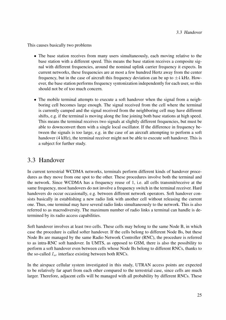
Aircraft fly usually at speeds around 900 km/h (15 km/min). This means signals transmitted andreceived from the aircraft will suffer a significantly greater Doppler frequency shift as mobileterminals on the ground, which move at much lower speeds. Figure 3.7 shows the evolution ofthe Doppler shift of the signal received at the aircraft as it flies by over the base station. Thecloser the aircraft flies by over the base station, the sharper the variation of Doppler shift. Themaximum shift is experienced when the aircraft is far from the base station, and is approximately2 kHz for typical aircraft cruising speeds.
In WCDMA, base stations use a very accurate local oscillator at the transmitter, so that thedifference in carrier frequency between two base stations is negligible. This accuracy require-ment is specified by 3GPP as follows: “The modulated carrier frequency of the base station shallbe accurate to within ±0.05 ppm." At a carrier frequency of 2 GHz, this means the maximumdifference in carrier frequency between any pair of base stations is 200 Hz.
The mobile terminals use a frequency acquisition circuit to syntonize accurately to the receivedfrequency from the base station. In this case, the accuracy requirement is specified as follows:
23
3 Analysis of aircraft specific constraints
Figure 3.7: Evolution of Doppler shift as aircraft flies by over base station
"The UE modulated carrier frequency shall be accurate to within ±0.1 ppm compared to the car-rier frequency received from the Node B." This accuracy is equivalent to±200 Hz. However, thereceived signal suffers a certain Doppler shift, so that the mobile terminal syntonizes to a shiftedfrequency. In current terrestrial networks, this shift is in the range of a few hundred Hertz, but inthe case of aircraft it could reach up to 2 kHz. Moreover, the transmitted signal from the terminal(which is itself already shifted) suffers an additional shift as seen from the base station receiver.This is illustrated in Figure 3.8
Figure 3.8: Doppler shift
24
3.3 Handover
This causes basically two problems
• The base station receives from many users simultaneously, each moving relative to thebase station with a different speed. This means the base station receives a composite sig-nal with different frequencies, around the nominal uplink carrier frequency it expects. Incurrent networks, these frequencies are at most a few hundred Hertz away from the centerfrequency, but in the case of aircraft this frequency deviation can be up to ±4 kHz. How-ever, the base station performs frequency syntonization independently for each user, so thisshould not be of too much concern.
• The mobile terminal attempts to execute a soft handover when the signal from a neigh-boring cell becomes large enough. The signal received from the cell where the terminalis currently camped and the signal received from the neighboring cell may have differentshifts, e.g. if the terminal is moving along the line joining both base stations at high speed.This means the terminal receives two signals at slightly different frequencies, but must beable to downconvert them with a single local oscillator. If the difference in frequency be-tween the signals is too large, e.g. in the case of an aircraft attempting to perform a softhandover (4 kHz), the terminal receiver might not be able to execute soft handover. This isa subject for further study.
3.3 Handover
In current terrestrial WCDMA networks, terminals perform different kinds of handover proce-dures as they move from one spot to the other. These procedures involve both the terminal andthe network. Since WCDMA has a frequency reuse of 1, i.e. all cells transmit/receive at thesame frequency, most handovers do not involve a frequency switch in the terminal receiver. Hardhandovers do occur occasionally, e.g. between different network operators. Soft handover con-sists basically in establishing a new radio link with another cell without releasing the currentone. Thus, one terminal may have several radio links simultaneously to the network. This is alsoreferred to as macrodiversity. The maximum number of radio links a terminal can handle is de-termined by its radio access capabilities.
Soft handover involves at least two cells. These cells may belong to the same Node B, in whichcase the procedure is called softer handover. If the cells belong to different Node Bs, but theseNode Bs are managed by the same Radio Network Controller (RNC), the procedure is referredto as intra-RNC soft handover. In UMTS, as opposed to GSM, there is also the possibility toperform a soft handover even between cells whose Node Bs belong to different RNCs, thanks tothe so-called Iur interface existing between both RNCs.
In the airspace cellular system investigated in this study, UTRAN access points are expectedto be relatively far apart from each other compared to the terrestrial case, since cells are muchlarger. Therefore, adjacent cells will be managed with all probability by different RNCs. These
25
3 Analysis of aircraft specific constraints
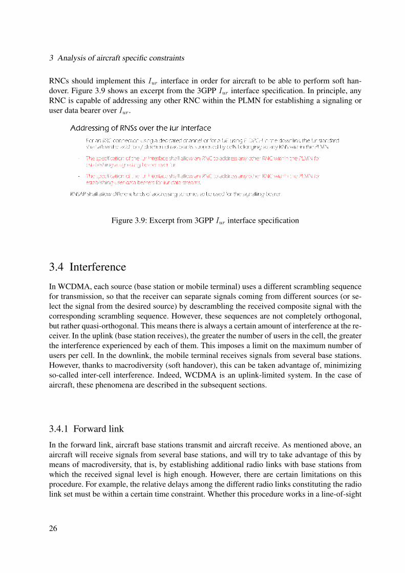
RNCs should implement this Iur interface in order for aircraft to be able to perform soft han-dover. Figure 3.9 shows an excerpt from the 3GPP Iur interface specification. In principle, anyRNC is capable of addressing any other RNC within the PLMN for establishing a signaling oruser data bearer over Iur.
Figure 3.9: Excerpt from 3GPP Iur interface specification
3.4 Interference
In WCDMA, each source (base station or mobile terminal) uses a different scrambling sequencefor transmission, so that the receiver can separate signals coming from different sources (or se-lect the signal from the desired source) by descrambling the received composite signal with thecorresponding scrambling sequence. However, these sequences are not completely orthogonal,but rather quasi-orthogonal. This means there is always a certain amount of interference at the re-ceiver. In the uplink (base station receives), the greater the number of users in the cell, the greaterthe interference experienced by each of them. This imposes a limit on the maximum number ofusers per cell. In the downlink, the mobile terminal receives signals from several base stations.However, thanks to macrodiversity (soft handover), this can be taken advantage of, minimizingso-called inter-cell interference. Indeed, WCDMA is an uplink-limited system. In the case ofaircraft, these phenomena are described in the subsequent sections.
3.4.1 Forward link
In the forward link, aircraft base stations transmit and aircraft receive. As mentioned above, anaircraft will receive signals from several base stations, and will try to take advantage of this bymeans of macrodiversity, that is, by establishing additional radio links with base stations fromwhich the received signal level is high enough. However, there are certain limitations on thisprocedure. For example, the relative delays among the different radio links constituting the radiolink set must be within a certain time constraint. Whether this procedure works in a line-of-sight
26
3.4 Interference
environment (with no fading) remains to be investigated. Inter-cell interference could play animportant role due to the line-of-sight nature of all links in the system.
If terrestrial frequencies are used, an additional probelem araises. Some existing terrestrial basestation antennas radiate partially skywards.The aircraft would therefore receive a significantamount of interference from these antennas, even at 10 km altitude, since there is line of sight.This could in principle be overcome by allowing a greater maximum transmit power at the air-craft base stations.Power control would ensure that signal-to-interference ratio at the receiver ishigh enough for the required performance.
3.4.2 Reverse Link
In the reverse link, aircraft transmit and aircraft base stations receive. Again, a base station willreceive a composite signal from several aircraft. If the number of aircraft grows, the performancewill become worse due to the non-orthogonality of the scrambling sequences. Power control willreact to this phenomenon and have users increase their power.Users at the cell boundary, notbeing able to increase their any more, will lose their connection. This dependency between thenumber of users and the cell size is known as cell breathing, and should be taken into account toavoid coverage gaps in high density scenarios.
If terrestrial frequencies are used, existing terrestrial base stations will also receive the compositesignal from aircraft, since they usually have a few skyward lobes. Power control will have mobileterminals increase their power to maintain the target signal-to-interference ratio, but users on thecell boundary won’t be able to increase their power any more, so they will lose their connection.In other words, the cell will shrink, possibly giving rise to coverage gaps.
27
3 Analysis of aircraft specific constraints
28
4 Air-to-ground link model
4.1 Concept description
In this section, we intend to show the relationship between the maximum allowable airspace cellradius (within which the aircraft link exhibits the desired performance) and the cost in terms oftransmit power increase required at the mobile terminal in order to maintain the performanceof the terrestrial link in presence of interference from the aircraft at the base station receiver. Inorder to do so, we will use the raw data obtained by conducting the simulations using the simula-tor that will be described in the chapter 5 and a few theoretical formulae that will be derived next.
Figure 4.1: Geometry involved in the terrestrial and aircraft components
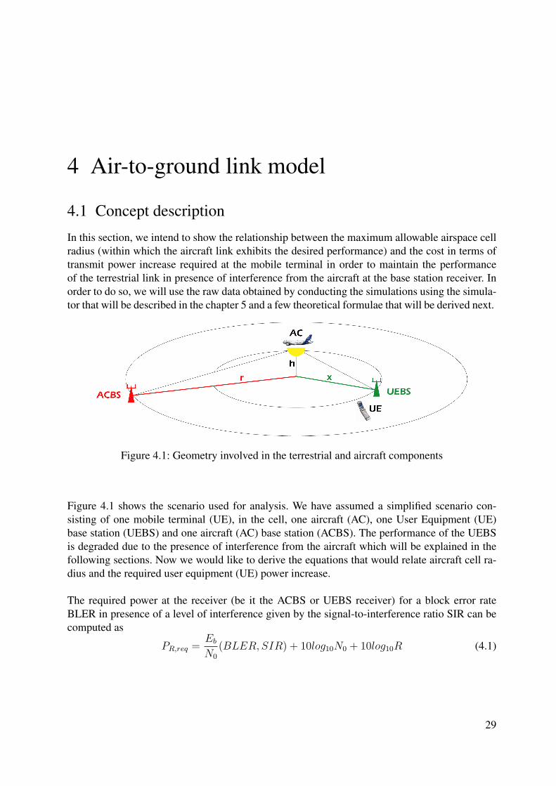
Figure 4.1 shows the scenario used for analysis. We have assumed a simplified scenario con-sisting of one mobile terminal (UE), in the cell, one aircraft (AC), one User Equipment (UE)base station (UEBS) and one aircraft (AC) base station (ACBS). The performance of the UEBSis degraded due to the presence of interference from the aircraft which will be explained in thefollowing sections. Now we would like to derive the equations that would relate aircraft cell ra-dius and the required user equipment (UE) power increase.
The required power at the receiver (be it the ACBS or UEBS receiver) for a block error rateBLER in presence of a level of interference given by the signal-to-interference ratio SIR can becomputed as
PR,req =Eb
N0
(BLER, SIR) + 10log10N0 + 10log10R (4.1)
29
4 Air-to-ground link model
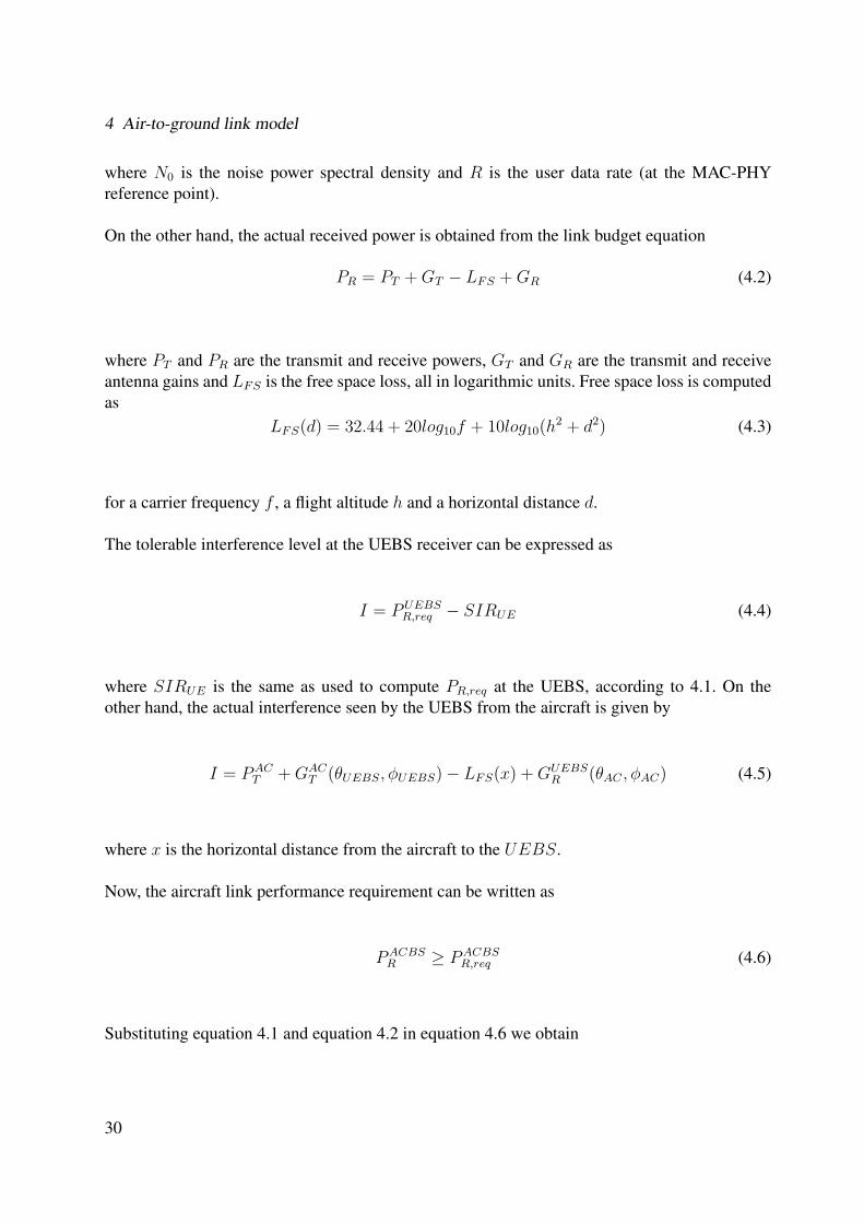
where N0 is the noise power spectral density and R is the user data rate (at the MAC-PHYreference point).
On the other hand, the actual received power is obtained from the link budget equation
PR = PT + GT − LFS + GR (4.2)
where PT and PR are the transmit and receive powers, GT and GR are the transmit and receiveantenna gains and LFS is the free space loss, all in logarithmic units. Free space loss is computedas
LFS(d) = 32.44 + 20log10f + 10log10(h2 + d2) (4.3)
for a carrier frequency f , a flight altitude h and a horizontal distance d.
The tolerable interference level at the UEBS receiver can be expressed as
I = PUEBSR,req − SIRUE (4.4)
where SIRUE is the same as used to compute PR,req at the UEBS, according to 4.1. On theother hand, the actual interference seen by the UEBS from the aircraft is given by
I = PACT + GAC
T (θUEBS, φUEBS)− LFS(x) + GUEBSR (θAC , φAC) (4.5)
where x is the horizontal distance from the aircraft to the UEBS.
Now, the aircraft link performance requirement can be written as
PACBSR ≥ PACBS
R,req (4.6)
Substituting equation 4.1 and equation 4.2 in equation 4.6 we obtain
30
4.1 Concept description
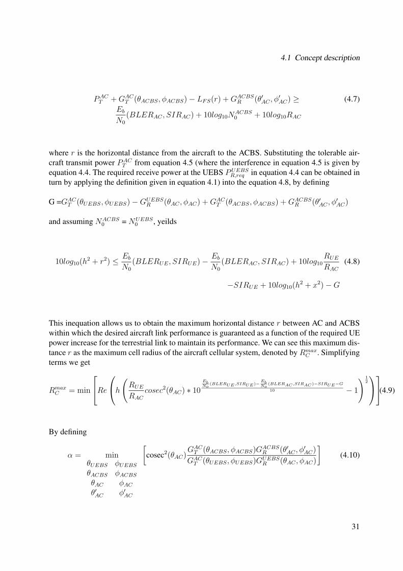
PACT + GAC
T (θACBS, φACBS)− LFS(r) + GACBSR (θ′AC , φ′
AC) ≥ (4.7)Eb
N0
(BLERAC , SIRAC) + 10log10NACBS0 + 10log10RAC
where r is the horizontal distance from the aircraft to the ACBS. Substituting the tolerable air-craft transmit power PAC
T from equation 4.5 (where the interference in equation 4.5 is given byequation 4.4. The required receive power at the UEBS PUEBS
R,req in equation 4.4 can be obtained inturn by applying the definition given in equation 4.1) into the equation 4.8, by defining
G =GACT (θUEBS, φUEBS)−GUEBS
R (θAC , φAC) + GACT (θACBS, φACBS) + GACBS
R (θ′AC , φ′AC)
and assuming NACBS0 = NUEBS
0 , yeilds
10log10(h2 + r2) ≤ Eb
N0
(BLERUE, SIRUE)− Eb
N0
(BLERAC , SIRAC) + 10log10RUE
RAC
(4.8)
−SIRUE + 10log10(h2 + x2)−G
This inequation allows us to obtain the maximum horizontal distance r between AC and ACBSwithin which the desired aircraft link performance is guaranteed as a function of the required UEpower increase for the terrestrial link to maintain its performance. We can see this maximum dis-tance r as the maximum cell radius of the aircraft cellular system, denoted by Rmax
C . Simplifyingterms we get
RmaxC = min
Re
h
(RUE
RAC
cosec2(θAC) ∗ 10
EbNo
(BLERUE,SIRUE)−EbNo
(BLERAC,SIRAC )−SIRUE−G
10 − 1
) 12
(4.9)
By defining
α = minθUEBS φUEBS
θACBS φACBS
θAC φAC
θ′AC φ′AC
[cosec2(θAC)
GACT (θACBS, φACBS)GACBS
R (θ′AC , φ′AC)
GACT (θUEBS, φUEBS)GUEBS
R (θAC , φAC)
](4.10)
31
4 Air-to-ground link model
and assuming the argument of the square root in equation 4.9 is positive, the maximum cell ra-dius when a single aircraft is present (SIRAC = ∞)
RmaxC = h
[α
RUE
RAC
∗ 10∆PUE
T +EbN0
(BLERUE,∞)−EbN0
(BLERAC,∞)−SIRUE
10 − 1
] 12
(4.11)
We can particularize this formula for hemispheric antenna patterns at AC and ACBS, as wellconsidering the worst case UEBS azimuth angle,by setting
GACT (θ, φ) = GAC
T = 3dBi
GACBSR (θ, φ) = GACBS
R = 3dBi
GUEBSR (θ, φ) = GUEBS
R (θ)
Substituting the above antenna patterns into equation 4.10, we get a simplified expression forα
α = minθ
[2cosec2(θ)
GUEBSR (θ)
](4.12)
Moreover, if both UE and AC have the same data rate and performance requirement, simpli-fying equation 4.11 yields
Rmaxc = h
[α ∗ 10
∆PUET −SIRUE
10 − 1
] 12
(4.13)
As this formula 4.13 indicates, the maximum cell radius grows linearly with flight altitude andhas approximately a square-root dependency with the power increase at the mobile terminal.
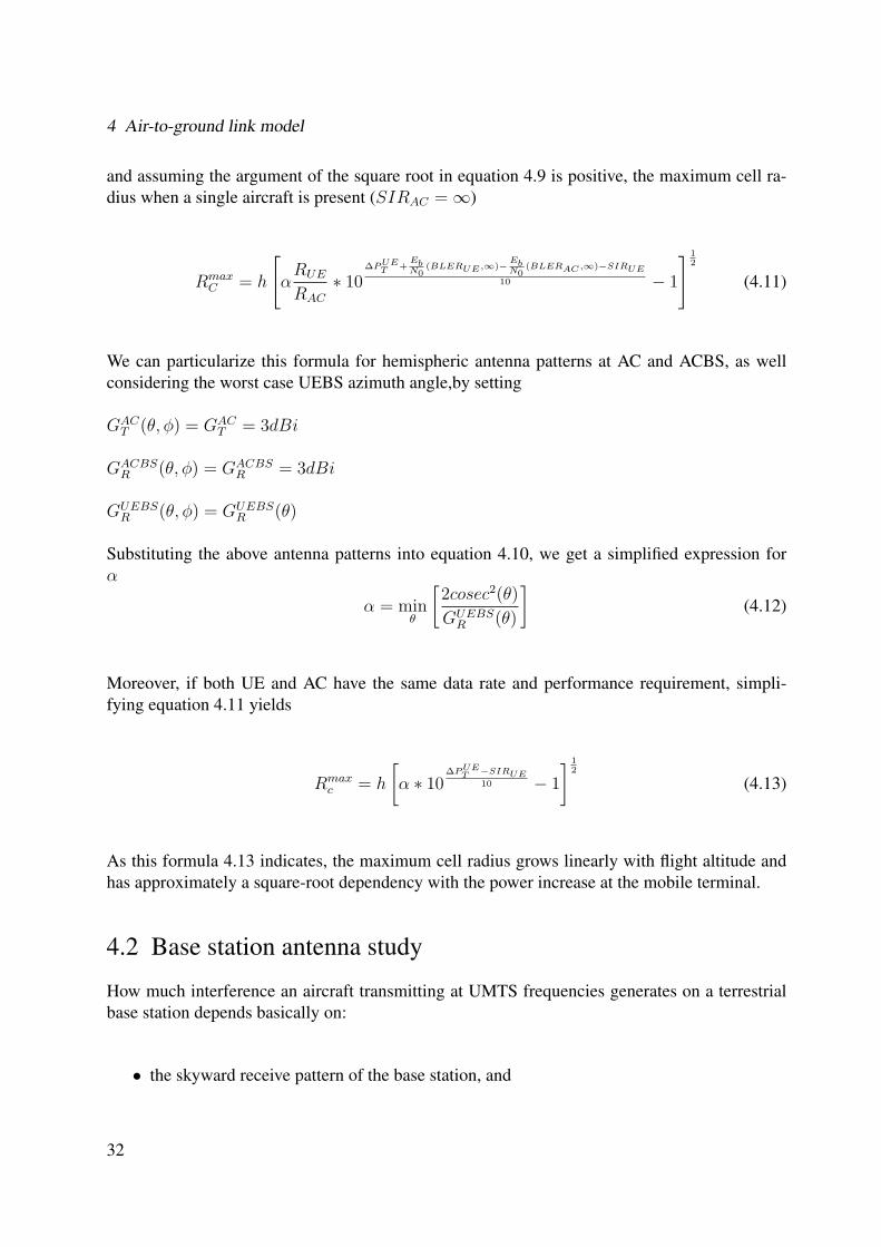
4.2 Base station antenna study
How much interference an aircraft transmitting at UMTS frequencies generates on a terrestrialbase station depends basically on:
• the skyward receive pattern of the base station, and
32
4.2 Base station antenna study
• the degree of quasi-orthogonality of the scrambling sequences used by mobile terminalsand aircraft.
Figure 4.2: Typical directional pattern of a base station panel antenna for mobile communications
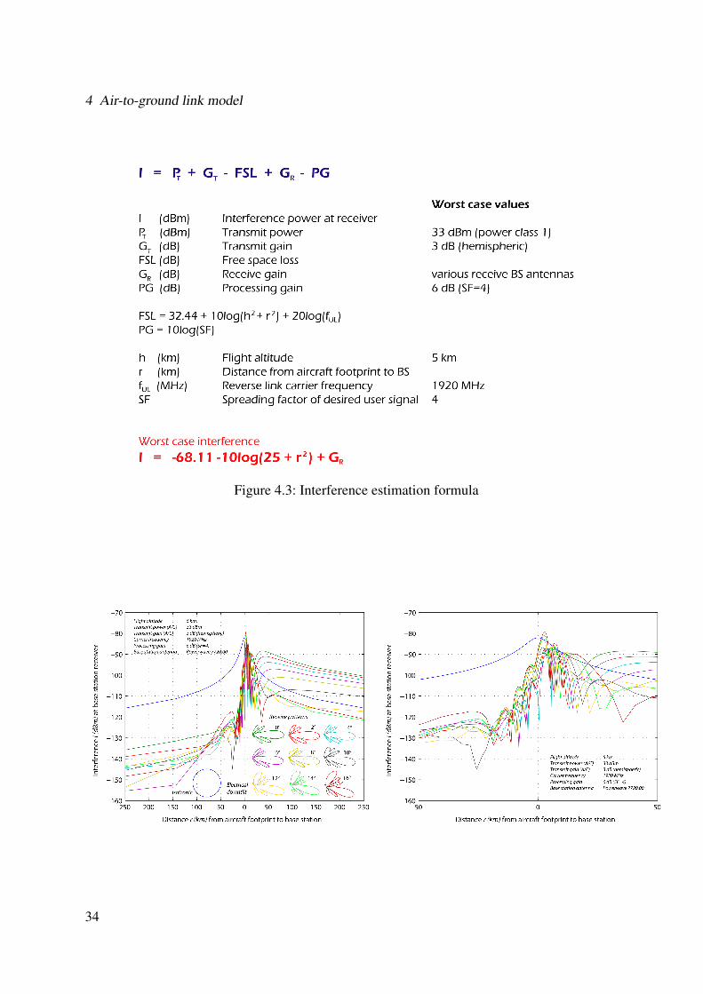
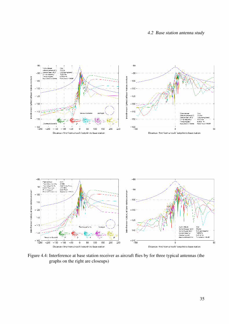
This section is dedicated to the first item. Figure 4.2 shows the three-dimensional radiation pat-tern of a typical base station panel antenna for mobile communications. The level of interferencereceived at the base station will vary depending on the position of the aircraft relative to the an-tenna. For example, if the aircraft is behind the antenna, interference is expected to be relativelylow, whereas directly in front of the main lobe, interference may increase significantly. Sincemost antennas are directional in azimuth, the worst scenario is chosen to be at 0 ◦ azimuth, seenin grey in Figure 4.2. Since there are many antennas on the ground within reach of the aircraftsignal, some of them will be pointing in the direction of the aircraft (in azimuth), wherever theaircraft is. Interference at the base station can be estimated according to the formula shown inFigure 4.3. Note: The processing gain PG is considered in order to obtain an estimate of theinterference level after chip processing at the WCDMA RAKE receiver. Applying this formulato a selection of typical base station antenna patterns obtained from a renowned mobile commu-nications antenna manufacturer, we get the graphs shown in Figure 4.4.
As seen from the figures the first antenna (top left) presents significant skyward side lobes, par-ticularly for high electrical down tilts. The other two antennas exhibit skyward side lobes withsmaller beamwidths. However, the most critical part of the pattern as regards interference fromaircraft seems to be the main lobe, especially when no down tilt is used at the antenna. Most an-tennas probably won’t receive much signal from the zenith, but they will definitely receive with ahigh gain from a horizontal elevation angle. This is a crucial factor in determining the feasibilityof an aircraft component in the UMTS licensed band.
33
4 Air-to-ground link model
Figure 4.3: Interference estimation formula
34
4.2 Base station antenna study
Figure 4.4: Interference at base station receiver as aircraft flies by for three typical antennas (thegraphs on the right are closeups)
35

4 Air-to-ground link model
36
5 Description of uplink WCDMA physicallayer simulator
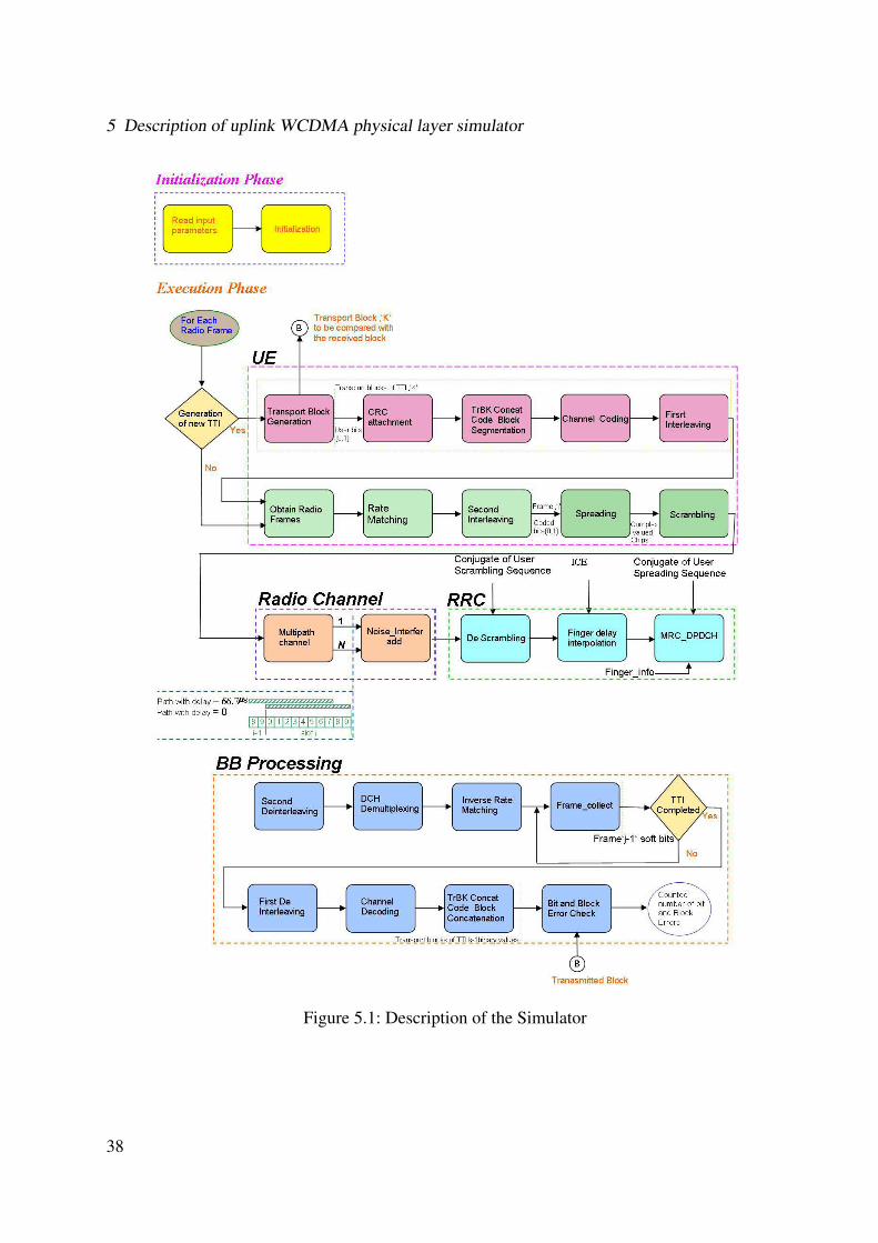
As a second task of this thesis, a physical layer simulator for uplink UTRA FDD has been imple-mented in JAVA. The simulator is designed for the four uplink reference measurement channels,as specified by the 3GPP that can be used for different UMTS Quality of Service (QoS). Asshown in Figure 5.1, the simulator consists of an initialization phase and an execution phase.During the initialization phase, we input all the values required to start the simulation which areread from a parameter file and these values can be changed accordingly for each simulation runbased on the reference measurement channel.
The execution phase consists of a loop that runs over the number of radio frames, which ispassed as a parameter and whose value can be varied, for achieving the desired performancerequirement of different UMTS Quality of Service. This is the main loop, during the executionof which we perform the operations that are done in the physical layer of the UE (User Equip-ment or transmitter). The data is then transmitted through different types of radio channels. Theinterference from the aircraft is considered at the receiver (Node B) of the terrestrial user. This isthen followed by a sub method in the main loop that describe the processing that takes place inthe Node B (base station), this sub method ends up in evaluating the errors (both bit and block)in the data received at the Node B (receiver) as compared to the original transmitted data.
Generally in UTRA the data generated at higher layers is carried over the air with transportchannels. Transport channels are mapped in the physical layer to different physical channels.Two types of transport channels exist, dedicated transport (dedicated) channel and common chan-nel. Here we consider only the dedicated transport channels for our implementation because thededicated transport channels carry all the information intended for the given user coming fromlayers above the physical layer, including the data for the actual service as well as higher layercontrol information which are mapped to dedicated control channel (DCCH), carrying the usercontrol data and dedicated transport channel (DTCH), carrying the user information data. Thedata generated in the DTCH is important as the execution phase ends up in performing the bitand block error rate evaluations of the user information data.
The data generation in the transport channels is executed by another sub loop inside the mainframe loop that runs twice for the user control and information data. During the execution ofeach run a new set of data for the specific transport channel is generated based on the conditionthat whether it is the periodicity at which a transport block (TB) is transferred by the physicallayer on the radio interface and this is always a multiple of the minimum interleaving period of
37
5 Description of uplink WCDMA physical layer simulator
Figure 5.1: Description of the Simulator
38
one radio frame (10ms).
After the generation of new set of data on each transport channel the data of each transportchannel (TrCH) must be processed.
Adding Cyclic Redundancy Check (CRC) bits to each transport block. The CRC bits help inthe error detection of the transport blocks. The size of the CRC could be 24, 16, 12, 8 or 0 bitsand it is generally signalled from higher layers, which is passed as a parameter for each transportchannel (TrCH).
After adding the CRC bits, concatenation of all the transport blocks in a transmission time in-terval (TTI) is performed. Code block segmentation operation is done if the number of bits ina TTI is larger than the size of a code block. The code block size varies depending on the typeof channel coding used for the transport channel. The code block size is ‘804’ if convolutionalcoding is used and it is ‘5114’ if turbo coding is used.
Code blocks are then delivered to the channel coding block. The following channel codingschemes have been applied to the data of the transport channels:
• Convolutional codingConvolutional coding with constraint length 9 and coding rate 1
3is applied. For this type of
coding scheme ‘8’ tail bits, equal to the length of the shift register used in the convolutionalencoder having a binary value ‘0’ must be added to the code blocks before the encoding,to ensure that the encoding process ends up in a a zero or initial state. The generatorpolynomials which describe the connection among shift registers and modulo 2 addersused for the Convolutional coding are 557(octal), 663(octal), 711(octal).
• Turbo codingThe scheme of turbo coder is a ‘Parallel Concatenated Convolutional Code’(PCCC) withtwo 8-state constituent encoders and one turbo code interleaver. The coding rate of turbocoder is 1
3. After the encoding operation, the encoders are forced back to the zero state and
this process is called trellis termination. The trellis termination is performed by padding12 bits of value ‘0’ after the encoding of the information bits.
The size of the encoded block,‘Yi’ is dependent on the coding scheme
• convolutional coding with rate 1/2 Yi=2*(size of code block)+16
• convolutional coding with rate 1/3 Yi=3*(size of code block)+24
• turbo coding with rate 1/3 Yi=3*(size of code block)+12
The choice of the channel coder can be done during the initialization phase depending on the typeof the coding used for the transport channel. After the channel encoding of each block of userinformation and control data, a ‘first interleaving’ operation is performed for reducing the burst
39
5 Description of uplink WCDMA physical layer simulator
errors introduced by the channel and the interleaver that has been used for our implementation isa block interleaver with inter column permutations, as specified by the 3GPP. The sub loop endsup in generating the users information and control data. This data requires a further processingin the physical layer before being transmitted over the channel.
When the transmission time interval of the transport Channel is longer than 10 ms, the inputbit sequence is segmented and mapped onto consecutive radio frames. Every 10 ms, one radioframe from each transport channel is multiplexed serially, first the user information data followedby the user control data. Rate matching operation is performed on the multiplexed data. In thisimplementation we perform the rate matching operation, when the rate matching pattern is usedto puncture the input data and we add a binary value of zero, when we need to repeat some datavalues of the user frame in order to conform to the specifications. The result of the rate matchingoperation is to obtain a coded composite transport channel (CCTrCH). The so formed compositetransport channels are interleaved by a ‘second interleaver’ which is a block interleaver that per-forms inter column permutations.
Now a mapping of the transport channels to the physical channels is carried in order to be trans-mitted over the air. A physical channel, in general is defined by its carrier frequency, channel-ization code (CDMA) and relative phase for the uplink connection. This phase is either 0 or π
2
corresponding to the in phase or quadrature component. In this implementation we consider thefollowing Physical Channels
DPDCH–Dedicated Physical Data Channel:-this carries the user control and information data. There may be zero, one or many DPDCHon each connection.
DPCCH–Dedicated Physical Control Channel:-this carries control information related to the physical layer. There is only one DPCCH oneach connection.
Transmission Characteristics:
The following transmission characteristics are used for all the Physical channels
• Modulationchip rate:3.84 Mcps
• Modulation:QPSK data and spreading modulation
The physical channels must be transformed to the transmission characteristics by applying thespreading operation which is described in the following section.
5.1 Overview of Spreading and Modulation
The spreading consists of two operations.
40
5.1 Overview of Spreading and Modulation
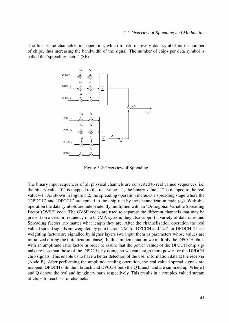
The first is the channelization operation, which transforms every data symbol into a numberof chips, thus increasing the bandwidth of the signal. The number of chips per data symbol iscalled the ‘spreading factor’ (SF).
Figure 5.2: Overview of Spreading
The binary input sequences of all physical channels are converted to real valued sequences, i.e,the binary value “0” is mapped to the real value +1, the binary value “1” is mapped to the realvalue−1 . As shown in Figure 5.2, the spreading operation includes a spreading stage where the‘DPDCH’ and ‘DPCCH’ are spread to the chip rate by the channelization code (cd). With thisoperation the data symbols are independently multiplied with an ‘Orthogonal Variable SpreadingFactor’(OVSF) code. The OVSF codes are used to separate the different channels that may bepresent on a certain frequency in a CDMA system, they also support a variety of data rates andSpreading factors, no matter what length they are. After the channelization operation the realvalued spread signals are weighted by gain factors ‘βc’ for DPCCH and ‘βd’ for DPDCH. Theseweighting factors are signalled by higher layers (we input them as parameters whose values areinitialized during the initialization phase). In this implementation we multiply the DPCCH chipswith an amplitude ratio factor in order to assure that the power values of the DPCCH chip sig-nals are less than those of the DPDCH, by doing, so we can assign more power for the DPDCHchip signals. This enable us to have a better detection of the user information data at the receiver(Node B). After performing the amplitude scaling operation, the real valued spread signals aremapped, DPDCH onto the I branch and DPCCH onto the Q branch and are summed up. Where Iand Q denote the real and imaginary parts respectively. This results in a complex valued streamof chips for each set of channels.
41
5 Description of uplink WCDMA physical layer simulator
The second operation is the scrambling operation, which is the key operation of the UTRAFDD. With the scrambling operation, all users can transmit on the same frequency and are dif-ferentiated by using a unique scrambling code (complex valued sequence). The receiver has thescrambling sequence of the user, descrambles the received signal to recovers the original data.The user data may be scrambled by either a long or a short scrambling code. In this implemen-tation we have used long scrambling codes which are essentially ‘Gold codes’. It is known fromtheory that largest sets of Gold codes have low cross correlational properties, so that as manyusers can use the channel with minimum mutual interference, which allows a less complicatedbase station design at the receiver without using an advanced receiver or interference canceler.There are (16777216) long scrambling codes. The long scrambling sequences are constructedfrom position wise modulo 2 sum of 38400 chip segments of two binary m-sequences, gener-ated by means of two generator polynomials of degree 25. The generated scrambling sequence isa pseudo random noise sequence (Gold sequence) improving the spectral properties of the signal.
In this implementation, we generate a new pair of scrambling sequences both for the user andthe interferer after every 100 runs of simulation (radio frames) because it might happen that oneparticular pair of generated scrambling sequences might have good auto and cross correlationproperties as compared to the other. By doing so we average the orthogonal properties of thescrambling codes which aids in producing precise results.
After spreading, the user data must be transmitted through the radio channel. Although the chan-nel is quite often out of the designer’s scope, a realistic channel model is an essential prerequisitefor the design of any communication system. In the study of signals and systems, the channel isviewed in terms of its input, its output and some description of how the input affects the output.If a channel was just a filter (Linear-time invariant system), then it could be completely char-acterized by its impulse response or frequency response. However, channels in practice have anextra ingredient: noise. For our implementation we use two types of channels that are mentionedin the following section.
5.2 Channel
AWGN channel : Additive White Gaussian Noise Channel is mainly used to estimate the channelcoders.
The variance of the noise generated by the AWGN channel is calculated from
• Eb
Nois the ratio of bit energy to noise power spectral density in (dB)
• Ec is the power of the input chip
• Lc is the number of chips in the transmitted signal
42
5.2 Channel
• Linf is the size of the user data per TTI
Eb
No
=
[Ec
No
] [Lchip
Linf
](5.1)
According to formula (5.1) ‘N0’ is the total one sided noise power spectral density of all noisesources.
Multipath Channel : This is the more realistic channel found in today’s mobile communicationsystems where the transmitted signal arrives at the receiver via multiple propagation paths at dif-ferent delays. There are two important characteristics of the multipath channel, one characteristicis the time spread introduced in the signal that is transmitted through the multipath channel i.e. ifwe transmit an extremely short pulse, ideally an impulse, over a time varying mutipath channel,the received signal might appear as a train of pulses occurring after different delays. The secondcharacteristic is due to the time variations in the structure of the medium. As a result of suchvariations, the nature of multipath varies with time. A ‘tapped delay line model’ was used forthe multipath channel which can be configured by passing parameters from outside of the block.Four cases were used that are specified according to the 3GPP specifications and multipath chan-nel block also adds noise, the variance of the noise is calculated according to formula (5.1).
Now the desired user signal is corrupted by the channel noise. This arrives at the base station(Node B). Here we have to consider the interference from the aircraft.The interference additionis performed directly by adding to the user data, the data from the aircraft at the receiver (NodeB). The interferer signal is normalized with this SIR value which can be passed as a parameterfrom outside and whose value can be varied depending on the number of aircraft.
The degraded user data (both the information and the control data) is now at the base stationwhich must be processed to extract the user information data.
At the receiver (base station or Node B) the sequence of operations done are inverse to thosethat are performed at the transmitter (User Equipment). First the received signal is descrambledby using the complex conjugate of the same scrambling sequence that is is used for the user atthe transmitter. Following the descrambling operation, the RAKE reception and maximum ratiocombining is carried if multipath channel is used for simulation. Otherwise, the descrambleddata is multiplied by the complex conjugate of the same spreading array that is used to spreadthe user data at the transmitter, to obtain an estimate of the user frame. The estimated user frameis deinterleaved by using the same intercolumn permutations that is used at the transmitter. Nextthe estimated frames are concatenated to obtain an estimate of the user transport blocks that wereactually delivered to the physical channel. After the concatenation of the user estimated framesthe first de interleaving operation is performed which is exactly the inverse of the interleavingoperation performed at the transmitter by using the same intercolumn permutations.
43
5 Description of uplink WCDMA physical layer simulator
Until now all the estimates of the user information data are in soft values and not in bits, nextwe do the channel decoding operation and we use soft decision decoding which yields a betterperformance than the hard decision decoding.
The output of the channel decoding are a sequence of estimates of the user data bit stream whichmust be sent into the bit error and block error rate evaluation blocks which yields the number ofbits and blocks that were different from original information data and these calculations are doneexcluding the Cyclic redundancy check bits.
44
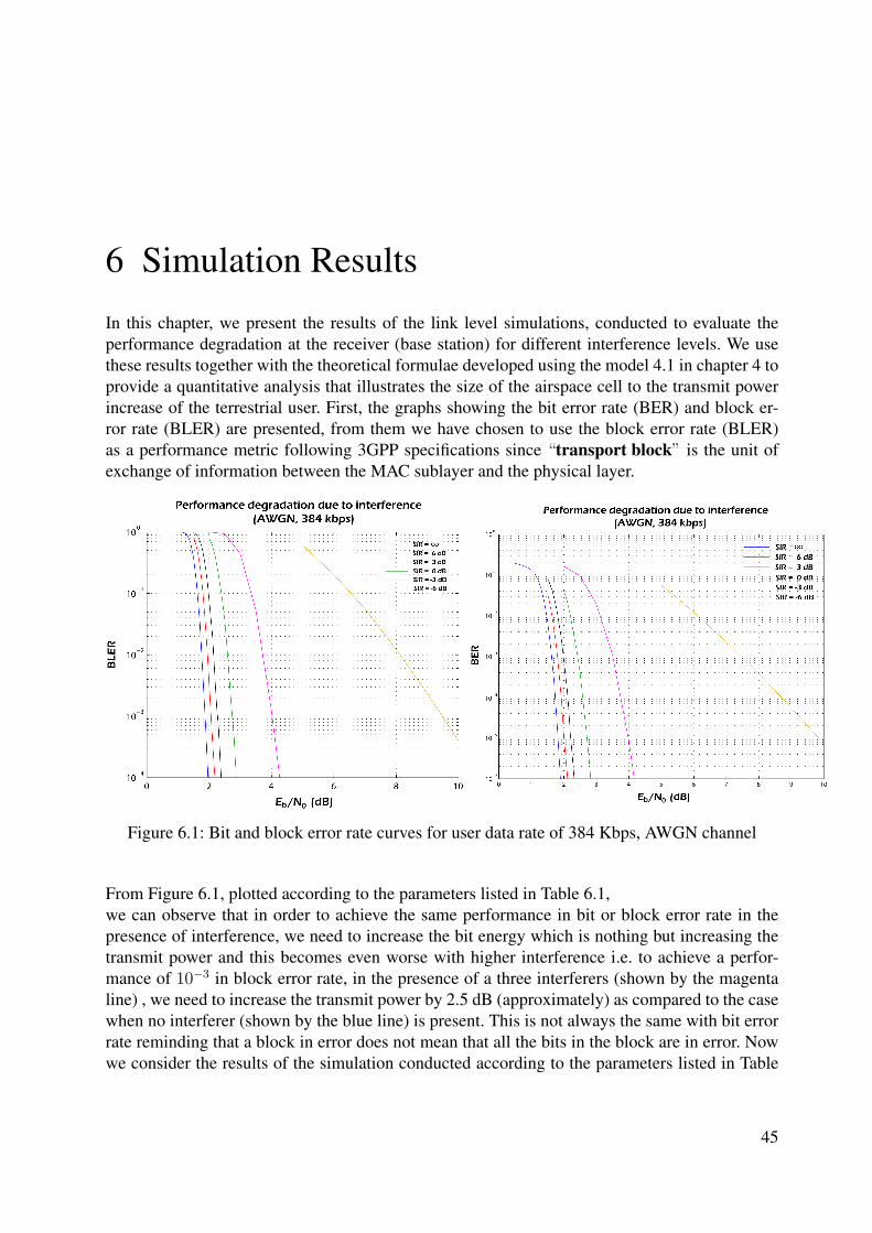
6 Simulation Results
In this chapter, we present the results of the link level simulations, conducted to evaluate theperformance degradation at the receiver (base station) for different interference levels. We usethese results together with the theoretical formulae developed using the model 4.1 in chapter 4 toprovide a quantitative analysis that illustrates the size of the airspace cell to the transmit powerincrease of the terrestrial user. First, the graphs showing the bit error rate (BER) and block er-ror rate (BLER) are presented, from them we have chosen to use the block error rate (BLER)as a performance metric following 3GPP specifications since “transport block” is the unit ofexchange of information between the MAC sublayer and the physical layer.
Figure 6.1: Bit and block error rate curves for user data rate of 384 Kbps, AWGN channel
From Figure 6.1, plotted according to the parameters listed in Table 6.1,we can observe that in order to achieve the same performance in bit or block error rate in thepresence of interference, we need to increase the bit energy which is nothing but increasing thetransmit power and this becomes even worse with higher interference i.e. to achieve a perfor-mance of 10−3 in block error rate, in the presence of a three interferers (shown by the magentaline) , we need to increase the transmit power by 2.5 dB (approximately) as compared to the casewhen no interferer (shown by the blue line) is present. This is not always the same with bit errorrate reminding that a block in error does not mean that all the bits in the block are in error. Nowwe consider the results of the simulation conducted according to the parameters listed in Table
45
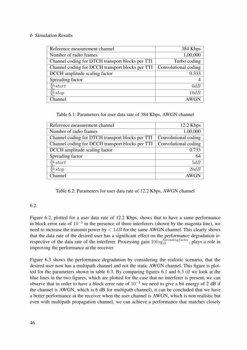
6 Simulation Results
Reference measurement channel 384 KbpsNumber of radio frames 1,00,000Channel coding for DTCH transport blocks per TTI Turbo codingChannel coding for DCCH transport blocks per TTI Convolutional codingDCCH amplitude scaling factor 0.333Spreading factor 4Eb
Nostart 0dB
Eb
Nostop 10dB
Channel AWGN
Table 6.1: Parameters for user data rate of 384 Kbps, AWGN channel
Reference measurement channel 12.2 KbpsNumber of radio frames 1,00,000Channel coding for DTCH transport blocks per TTI Convolutional codingChannel coding for DCCH transport blocks per TTI Convolutional codingDCCH amplitude scaling factor 0.733Spreading factor 64Eb
Nostart 5dB
Eb
Nostop 20dB
Channel AWGN
Table 6.2: Parameters for user data rate of 12.2 Kbps, AWGN channel
6.2.
Figure 6.2, plotted for a user data rate of 12.2 Kbps, shows that to have a same performancein block error rate of 10−3 in the presence of three interferers (shown by the magenta line), weneed to increase the transmit power by < 1dB for the same AWGN channel. This clearly showsthat the data rate of the desired user has a significant effect on the performance degradation ir-respective of the data rate of the interferer. Processing gain 10logSpreadingfactor
10 , plays a role inimproving the performance at the receiver.
Figure 6.3 shows the performance degradation by considering the realistic scenario, that thedesired user now has a multipath channel and not the static AWGN channel. This figure is plot-ted for the parameters shown in table 6.3. By comparing figures 6.1 and 6.3 (if we look at theblue lines in the two figures, which are plotted for the case that no interferer is present, we canobserve that in order to have a block error rate of 10−3 we need to give a bit energy of 2 dB ifthe channel is AWGN, which is 6 dB for multipath channel), it can be concluded that we havea better performance at the receiver when the user channel is AWGN, which is non realistic buteven with multipath propagation channel, we can achieve a performance that matches closely
46
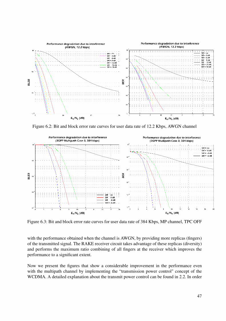
Figure 6.2: Bit and block error rate curves for user data rate of 12.2 Kbps, AWGN channel
Figure 6.3: Bit and block error rate curves for user data rate of 384 Kbps, MP channel, TPC OFF
with the performance obtained when the channel is AWGN, by providing more replicas (fingers)of the transmitted signal. The RAKE receiver circuit takes advantage of these replicas (diversity)and performs the maximum ratio combining of all fingers at the receiver which improves theperformance to a significant extent.
Now we present the figures that show a considerable improvement in the performance evenwith the multipath channel by implementing the “transmission power control" concept of theWCDMA. A detailed explanation about the transmit power control can be found in 2.2. In order
47
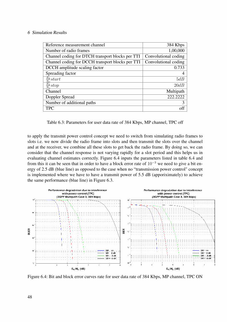
6 Simulation Results
Reference measurement channel 384 KbpsNumber of radio frames 1,00,000Channel coding for DTCH transport blocks per TTI Convolutional codingChannel coding for DCCH transport blocks per TTI Convolutional codingDCCH amplitude scaling factor 0.733Spreading factor 4Eb
Nostart 5dB
Eb
Nostop 20dB
Channel MultipathDoppler Spread 222.2222Number of additional paths 3TPC off
Table 6.3: Parameters for user data rate of 384 Kbps, MP channel, TPC off
to apply the transmit power control concept we need to switch from simulating radio frames toslots i.e. we now divide the radio frame into slots and then transmit the slots over the channeland at the receiver, we combine all these slots to get back the radio frame. By doing so, we canconsider that the channel response is not varying rapidly for a slot period and this helps us inevaluating channel estimates correctly. Figure 6.4 inputs the parameters listed in table 6.4 andfrom this it can be seen that in order to have a block error rate of 10−3 we need to give a bit en-ergy of 2.5 dB (blue line) as opposed to the case when no “transmission power control" conceptis implemented where we have to have a transmit power of 5.5 dB (apporiximately) to achievethe same performance (blue line) in Figure 6.3.
Figure 6.4: Bit and block error curves rate for user data rate of 384 Kbps, MP channel, TPC ON
48
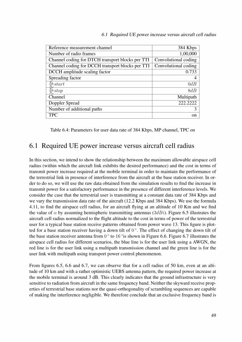
6.1 Required UE power increase versus aircraft cell radius
Reference measurement channel 384 KbpsNumber of radio frames 1,00,000Channel coding for DTCH transport blocks per TTI Convolutional codingChannel coding for DCCH transport blocks per TTI Convolutional codingDCCH amplitude scaling factor 0.733Spreading factor 4Eb
Nostart 0dB
Eb
Nostop 8dB
Channel MultipathDoppler Spread 222.2222Number of additional paths 3TPC on
Table 6.4: Parameters for user data rate of 384 Kbps, MP channel, TPC on
6.1 Required UE power increase versus aircraft cell radius
In this section, we intend to show the relationship between the maximum allowable airspace cellradius (within which the aircraft link exhibits the desired performance) and the cost in terms oftransmit power increase required at the mobile terminal in order to maintain the performance ofthe terrestrial link in presence of interference from the aircraft at the base station receiver. In or-der to do so, we will use the raw data obtained from the simulation results to find the increase intransmit power for a satisfactory performance in the presence of different interference levels. Weconsider the case that the terrestrial user is transmitting at a constant data rate of 384 Kbps andwe vary the transmission data rate of the aircraft (12.2 Kbps and 384 Kbps). We use the formula4.11, to find the airspace cell radius, for an aircraft flying at an altitude of 10 Km and we findthe value of α by assuming hemispheric transmitting antennas (3dBi). Figure 6.5 illustrates theaircraft cell radius normalized to the flight altitude to the cost in terms of power of the terrestrialuser for a typical base station receive patterns obtained from power wave 13. This figure is plot-ted for a base station receiver having a down tilt of 0 ◦. The effect of changing the down tilt ofthe base station receiver antenna from 0 ◦ to 16 ◦is shown in Figure 6.6. Figure 6.7 illustrates theairspace cell radius for different scenarios, the blue line is for the user link using a AWGN, thered line is for the user link using a multipath transmission channel and the green line is for theuser link with multipath using transport power control phenomenon.
From figures 6.5, 6.6 and 6.7, we can observe that for a cell radius of 50 km, even at an alti-tude of 10 km and with a rather optimistic UEBS antenna pattern, the required power increase atthe mobile terminal is around 3 dB. This clearly indicates that the ground infrastructure is verysensitive to radiation from aircraft in the same frequency band. Neither the skyward receive prop-erties of terrestrial base stations nor the quasi-orthogonality of scrambling sequences are capableof making the interference negligible. We therefore conclude that an exclusive frequency band is
49
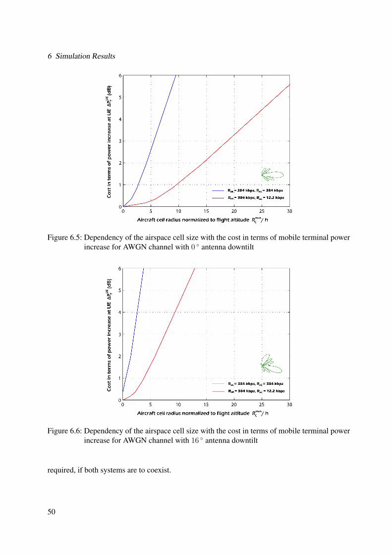
6 Simulation Results
Figure 6.5: Dependency of the airspace cell size with the cost in terms of mobile terminal powerincrease for AWGN channel with 0 ◦ antenna downtilt
Figure 6.6: Dependency of the airspace cell size with the cost in terms of mobile terminal powerincrease for AWGN channel with 16 ◦ antenna downtilt
required, if both systems are to coexist.
50
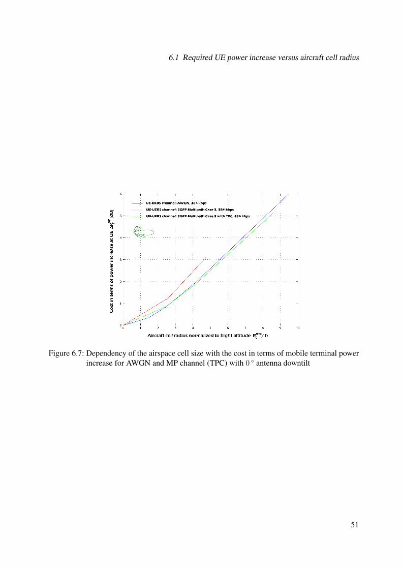
6.1 Required UE power increase versus aircraft cell radius
Figure 6.7: Dependency of the airspace cell size with the cost in terms of mobile terminal powerincrease for AWGN and MP channel (TPC) with 0 ◦ antenna downtilt
51
6 Simulation Results
52
7 Conclusions and Outlook
In this thesis, we have investigated the possibility of using UMTS for direct air-to-ground com-munications. This thesis has focused on the WCDMA air interface between Node B and UE atthe physical layer, assuming that an aircraft takes the role of a UE.
In chapter (2), we mention the main design aspects of WCDMA that support a variety of func-tions like high variable user data rates, the basic modes of operation (FDD, TDD), the operationasynchronous base stations etc. The principle of power control has been discussed. The powercontrol concept is critical, since it is the main form of resource allocation which is particularlyimportant on the uplink where we have the many to one scenario. Without power control a singleover powered mobile will block the whole cell. We also describe about different kinds of han-dover principles (soft, softer and inter RNC) that the UE can perform to maintain an ongoing call.We present the UMTS system architecture with a short introduction to all the network elementsof the architecture and the different interfaces between these elements.
In chapter (3), we consider the idea of reproducing the cellular structure of the terrestrial UMTSin the airspace. Some aircraft specific constraints, such as Doppler shift, propagation delay, han-dover and interference have been identified and analyzed. Doppler shift occurs in terrestrial net-works on a much smaller scale, since mobile stations on the ground move at much lower speeds.However, WCDMA receivers are equipped with powerful frequency acquisition circuits, capableof counteracting this effect. We have also shown that propagation delay has no significant effecton the power control mechanism. Finally, we have seen how UMTS networks can perform han-dover procedures between remote parts of the network, thanks to the Iur interface.
Chapter (4) presents a prototype that illustrates the direct air-to-ground communication link.Based on this model, we derive the equations relating the airspace cell radius and the cost interms of transmitter power increase at the terrestrial UE in the presence of interference from theaircraft. Later, we have concentrated on the receive patterns of the base station antennas, thatprovide us a first impression of the increase in the level of interference based on the position ofthe aircraft relative to the base station due to the skyward receive properties of the base stationantennas. We mention the formula for evaluating the interference from the aircraft at the basestation based on the link budget calculation and from this formula, we estimate the values forthe worst case interference. Chapter(5) describes in detail about the simulator that has been usedthroughout this thesis work for conducting link level simulations.
During this thesis, we have focused much of our study on analyzing the possibility of usingUMTS terrestrial frequencies for an aircraft component. It can be observed from the simulation
53
7 Conclusions and Outlook
results shown in chapter(6), that an aircraft component transmitting at these frequencies woulddegrade the performance of the existing network to an intolerable extent due to interference. Thisis mainly because the skyward characteristics of the mobile communication antennas deployedon the ground are such that any signal being transmitted at the UMTS reverse link frequenciesfrom the sky would cause significant interference on the base stations.
The terrestrial network would react to this interference automatically by means of power con-trol, commanding all users to increase their power. This produces the so-called “cell breathing”effect, which in this case makes the cell shrink, potentially leaving some users out of coverage,or reducing the data rate they can achieve. In order for the aircraft to degrade the performanceof the terrestrial network only to a tolerable extent, it would need to transmit at extremely lowpower. The airspace cells would then have to be so small that the system would be impractical.
A lot of research work remains to be done. An important aspect in network planning is the distri-bution of users over the area where the network will be deployed. In this respect, an interestinginput for a further study would be the aircraft distribution over the European airspace, particu-larly at rush hours, so that typical and maximum aircraft densities can be estimated. From thisdata, traffic demand and multiple access interference considerations would lead to an estimationof the appropriate cell size for the aircraft cellular system.
The results of this study should now be focussed on the survey of potential frequency bands,as well as an investigation of alternative technologies, in particular for the radio interface be-tween aircraft and ground network.
54
A State of the art analysis
There are currently several companies in the United States intending to provide voice calls andInternet access on airplanes. They all agree that 2006 won’t be the year that cell phones and othervoice devices are widely usable on aircraft. They also agree that 2007 is a much more likely time-frame due.
The delay has less to do with developing technology than it does with regulatory and spec-trum issues and satellite issues. And time also is needed to sort out the social issues related toproviding voice service in the air. Many fliers have expressed deep concern about the noise andinconvenience of having a plane full of people talking on their phones at the same time.
However, the time is coming when voice calls and Internet access in the air will be common.First will come data access via Wi-Fi, a type of access that already can be found on a couplehundred long-haul planes today.
A.1 How voice will be added
Cell services will be added to existing aircraft by installing an on-board picocell, or a tiny cellulartransmitter that would support GSM in Europe and both GSM and CDMA in the U.S. Depend-ing on an airline’s needs, the picocell could support just U.S. cell frequencies aboard domesticairliners or all frequencies used worldwide for cellular transmissions.
The picocell converts cellular packets into pure data for air-to-ground or air-to-satellite trans-mission. A ground station then pops the calls back into the phone system for completion. By thetime the on-board equipment is installed, it’s likely that older 2.5G and newer 3G services likeGPRS, EV-DO, UMTS or HSDPA will be available.
Equipment manufacturers, airlines, and in-air telecom firms have completed tests in the U.S.and abroad to demonstrate that the technology already exists to make these offerings work andthat they are safe to operate on planes.
55
A State of the art analysis
A.2 Regulations
Three roadblocks remain to rolling out these in-the-air voice and data services for which thetechnology already exists. The first is an auction by the Federal Communications Commission(FCC) of a small swath of spectrum in the 800 MHz range, which the FCC is repurposing fordirect air-to-ground communications. The auction will take place on May 10, 2006 and therecould be one or two winners.
The second involves both the Federal Aviation Administration (FAA) and the FCC. The FAAwants continued testing to ensure that operation of cell phones on planes won’t cause any unin-tentional interference with on-board avionics, as well as ensuring that, for security reasons, theservice has the right controls. A pilot, for example, should be able to sever the voice link forpassengers.
The FCC’s interest lies in licenses that cellular carriers own for frequencies on the ground thatwinning bidders for the air-to-ground spectrum would like to use on an aircraft so that existingcellular devices would work. (Similar issues in other countries may be resolved sooner).
The other broad area of concern can best be classified as social issues. Many, including somein the airline industry, have expressed concern about how annoying it could be to be in a planefull of people having cell phone conversations.
A.3 Some Players
Of the several companies likely to make hay from the U.S. bidding, only Connexion by Boeinghas a currently-operating data service on commercial flights, and only on long-haul fights bynon-U.S. carriers. The other important firms are OnAir, AirCell and Verizon AirFone, each ofwhich currently operates in a unique niche in the aeronautical telecom or data worlds.
A.3.1 Connexion by Boeing
Connexion uses a satellite downlink to provide access. Its service is installed on an estimated 200planes operated by seven airlines, including extensive long-haul routes run by Lufthansa. Twomore airlines will be added soon, while more are committed for future deployment. Connexionhas a slight incumbent benefit as a division of airplane maker Boeing.
The service offers 5 Mbps downstream and 1 Mbps upstream, although each user may be throt-tled to lower download speeds. Voice-over-IP is a popular use for the service, which can cost$10 to $35 per flight depending on payment plan and flight duration. While Connexion hasn’tformally stated it will bid on the air-to-ground spectrum, they do plan to add voice service onceregulatory issues are resolved.Connexion serves just nine airlines, all non-U.S., on 170 flights. Its
56
A.3 Some Players
business plan focuses on long-haul flights by wide-body aircraft and doesn’t include significantNorth American domestic traffic.
A.3.2 OnAir
Satellite-based rival OnAir is a joint venture formed early 2005 from the assets of Tenzing, anearly Connexion competitor that was formed by ex-Boeing employees, along with Airbus andSITA, a European airline-owned systems integrator.
OnAir is in a holding pattern at the moment as its satellite partner Inmarsat launches fourth-generation broadband "birds" with beam-focusing abilities. The second of three satellites launchedin early November, but shakedown will take some time. OnAir expects limited aeronautic broad-band to be turned on by late 2006; this will allow them to offer GSM-based cellular voice servicein Europe. It will offer data services via modules that will ultimately offer 432 Kbps each perplane, with longer-haul aircraft having two or four modules (864 Kbps or 1.7 Mbps).
OnAir is not expected to be part of the U.S. spectrum auctions but could partner with a winningbidder to allow overseas flights to hand off from expensive satellite to cheaper ground bandwidth.
A.3.3 AirCell
US-based AirCell has a long history of operating air-to-ground telecommunications stationsacross the country for private flights. The company has an advantage: as an equipment maker,they’ll benefit from selling gear to a winning spectrum bidder even if their bid fails.
AirCell has installed special upturned antennas on an existing 125 cellular base stations acrossthe US, with which it plans to backhaul data and voice over WiFi connections, passing themon into the PSTN network, without the need for a satellite. In late 2005 AirCell announced thesuccessful completion of its extended airborne demonstration program that allowed potential air-line customers and others to experience the AirCell Broadband System’s technology in flight.Targeted for commercial deployment in 2007, the AirCell Broadband System will enable air-line passengers to use their own Wi-Fi and cellular devices such as laptops, PDAs, phones andBlackberries in a fully integrated wireless cabin over an affordable, broadband air-to-ground link.
AirCell has accumulated hundreds of hours of hands-on flight test experience with airbornewireless broadband, and the demonstration program marked a number of important technologicalfirsts achieved by the company: the first end-to-end demonstration of wireless broadband usinga direct air-to-ground link; the first use of advanced wireless technology for a broadband air-to-ground link; the first support of CDMA, GSM, VoIP and Wi-Fi over a common air-to-groundpipe; the smallest broadband antenna ever used in aviation (weighs 5 ounces; 4" tall); the highestspeeds, altitudes and distances ever reached for EVDO technology.
The infrastructure on the plane consists of a picocell and a hotspot environment for mobile and
57
A State of the art analysis
WiFi, forwarding data to a front-end converter which sends an IP signal over a 3 megabit pipe tothe antennas on the ground.
The flight demonstration program showcased an advanced technology prototype of the AirCellBroadband System. Key demonstration system components and technical features included:
• A Broadband Air-to-Ground Link that uses custom-designed EVDO wireless technology.The link provides a high-speed connection directly from the aircraft to the ground, deliv-ering a "to-the-seat" user experience similar to a DSL link on the ground.
• A Cabin Telecommunications Router (CTR) that provides a high-speed, in-cabin hotspotfor Wi-Fi-equipped devices (802.11b/g) including Voice over Internet Protocol (VoIP)phones.
• Multiple Cabin Picocells supporting CDMA and GSM voice communications for commer-cial cell phones.
AirCell remains the only company ever to receive regulatory approval to use cellular frequen-cies for airborne telecommunications. Having operated its own terrestrial network in the UnitedStates for many years, AirCell has more patents and experience applying cellular technology inthe airborne environment than any organization in the world.
Building on its success, the company is now leveraging this unique experience in developingits next generation of airborne connectivity – bringing affordable broadband voice and data ser-vices to airline passengers. Operating over a new, next-generation digital network in North Amer-ica, the AirCell Broadband System is targeted for commercial deployment in 2007. Pending theacquisition of the spectrum license from the FCC, the AirCell network will initially cover thecontinental U.S. and will be expandable to include Canada, Mexico and the Caribbean. AirCell’ssystem will be US- or, at best, North America-specific, whereas the satellite-based services canclearly extend across the globe. There is a possibility that OnAir could use the AirCell networkfor the North American portion of long-haul flights, then switch to satellite when necessary. Thiswould lower its costs for that portion, enabling either more competitive pricing or fatter margins,depending on the competitive environment when it comes to market, which is also set for thesecond half of 2006.
A.3.4 Verizon AirFone
Verizon AirFone has the incumbent advantage – it still has seatback phones on many airlinersand has had no airborne competitors for several years. Calls from seatbacks and armrests overthe U.S. are almost entirely made over their existing network.
Verizon AirFone will retain a sliver of frequency for use with their older technology for callingregardless of the auction’s outcome, but the company is eager to upgrade services. It is expected
58
A.4 Auction News
that it would take about a year from the close of an FCC auction to have equipment manufac-tured, tested in the air, and up and running on a commercial basis. Verizon is well positioned tobid in the auction and could win the full bandwdith. It has a significant advantage on the manyplanes already equipped with their service. A new antenna would need to be added on the plane’sbelly.
Verizon expects at least 2.4 Mbps connections to the ground through a network of 130 to 150base stations. Even with a number of planes in the air connecting to the same base stations, theuser would experience very high speeds, comparable to DSL.
If Verizon wins control of the air-to-ground channel, it is expected that Boeing would cut adeal with the wireless company so that its Connexion customers could use the Verizon networkaboard aircraft flying domestically and not equipped with the satellite system.
That would leave Boeing tiny profit margins for service on those domestic flights, but at leastwould provide full coverage so that Connexion wouldn’t lose customers.
Verizon aims to begin service just a year after it wins the license. The company can use itscell towers as sites for the ground stations.
Verizon plans to partner with other wireless companies so that passengers can access the ser-vice through their own providers. It will be able to offer passengers rates comparable to hotelInternet rates, which he cited as $11 to $15 a day. Connexion charges $27 for a day.
All major U.S. carriers have expressed interest in the Verizon system, including prospectiveConnexion customers who want to integrate the two systems - using Connexion for transoceanicflight and air-to-ground domestically. No one really knows how high the auction bids will gobecause the air-to-ground airwaves will service a niche market of uncertain size.
The FCC does not pin a value on the airwaves, but spectrum auctions typically fetch a priceabout five times the pre-set minimum opening bid. Based on that rule of thumb, the bidding forthe key air-to-ground airwaves could go to around $15 million. But that’s only the beginningof the required investment. Whoever wins must then build ground infrastructure, court airlinecustomers, install equipment on airplanes and market to passengers.
A.4 Auction News
The Federal Communications Commission’s (FCC) auction of two nationwide Air-Ground spec-trum licenses in the 800 MHz band ended on June 2, 2006, the auction began on May 10,2006 and closed after 144 rounds of bidding. The winning bidders for the two licenses wereAC BidCo LLC and LiveTV,LLC. Ac Bidco, which teamed up with AirCell Inc., has won thethree megahertz of spectrum. That is enough capacity to offer in-flight Internet services. LiveTV
59
A State of the art analysis
has won the one megahertz spectrum will become a wholly subsidiary of JetBlue Airways whichis Newyork’s low-fare airline. This spectrum is enough for services such as communications withcockpit from the ground.
The four MHz of Air-Ground spectrum in the 800 MHz band can be used to provide a rangeof communications services to passengers on commercial and other aircraft, including broad-band internet access. The auction however does not affect the Federal Aviation Administration’s(FAA’s) and aircraft operator’s rules and policies restricting the use of personal electronic devices(PEDs) on aircraft. In addition, the auction does not affect the FCC’s ban on the use of wirelesstelephones on airplanes, which is intended to help prevent possible interference to terrestrialwireless systems.
60
B Performance of RAKE Receiver
Now, we present the simulation results, used to evaluate the functionality of the RAKE receivercircuit used in the simulator 5 and to compare it with the theoretical Rake receiver performanceobtained from 21.
Let us consider the transmission of binary signals (S1, S2) that have equal energy and are an-tipodal (S1 = - S2). In order to derive the error rate performance of the RAKE receiver, we haveassumed that the channel estimates are perfect. This is possible if the channel fading is suffi-ciently low, i.e. ∆tc
T≥ 100 where T is the signaling interval and ∆tc is the coherence time of
the channel. Furthermore, we assume that the spreading codes generated from pseudo randomsequences are perfectly orthogonal, which result in signals that have good cross and auto corre-lation properties. The formulae below B gives us a procedure to calculate the error probabilityusing the RAKE receiver.
BER =1
2
L∑k=1
Xk
[1−
√γk(1− ρr)
2 + γk(1− ρr)
](B.1)
where ‘L’ defines the number of paths or fingers, ρr is ‘-1’ for antipodal signals
Xk is defined as
Xk =L∏
i = 1i 6= k
γk
γk − γi
(B.2)
and γk is the average SNR for the kth path, defined as
γk =Eb
No
(linear)E(αk)2 (B.3)
Where E(αk)2 is the mean square value of the channel impulse response of the kth path.
61
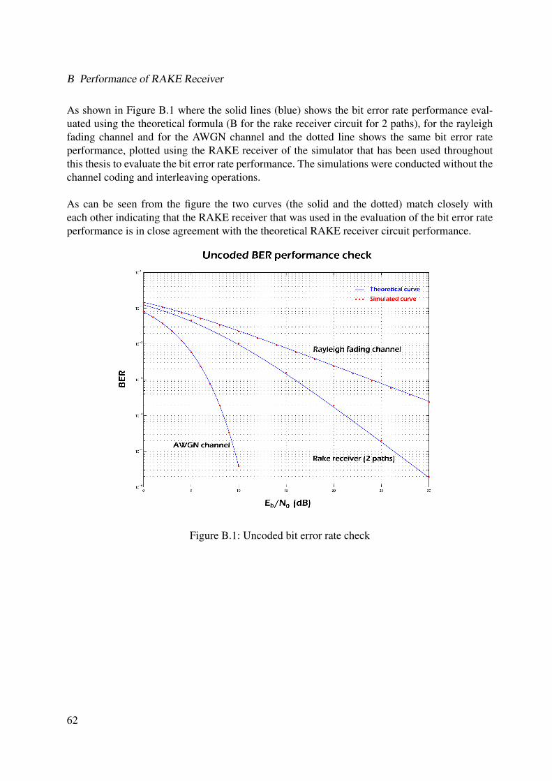
B Performance of RAKE Receiver
As shown in Figure B.1 where the solid lines (blue) shows the bit error rate performance eval-uated using the theoretical formula (B for the rake receiver circuit for 2 paths), for the rayleighfading channel and for the AWGN channel and the dotted line shows the same bit error rateperformance, plotted using the RAKE receiver of the simulator that has been used throughoutthis thesis to evaluate the bit error rate performance. The simulations were conducted without thechannel coding and interleaving operations.
As can be seen from the figure the two curves (the solid and the dotted) match closely witheach other indicating that the RAKE receiver that was used in the evaluation of the bit error rateperformance is in close agreement with the theoretical RAKE receiver circuit performance.
Figure B.1: Uncoded bit error rate check
62
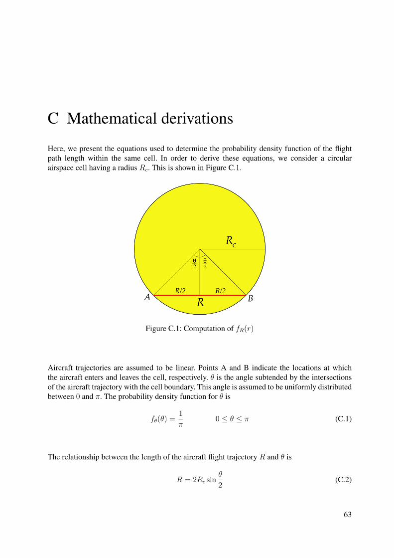
C Mathematical derivations
Here, we present the equations used to determine the probability density function of the flightpath length within the same cell. In order to derive these equations, we consider a circularairspace cell having a radius Rc. This is shown in Figure C.1.
Figure C.1: Computation of fR(r)
Aircraft trajectories are assumed to be linear. Points A and B indicate the locations at whichthe aircraft enters and leaves the cell, respectively. θ is the angle subtended by the intersectionsof the aircraft trajectory with the cell boundary. This angle is assumed to be uniformly distributedbetween 0 and π. The probability density function for θ is
fθ(θ) =1
π0 ≤ θ ≤ π (C.1)
The relationship between the length of the aircraft flight trajectory R and θ is
R = 2Rc sinθ
2(C.2)
63
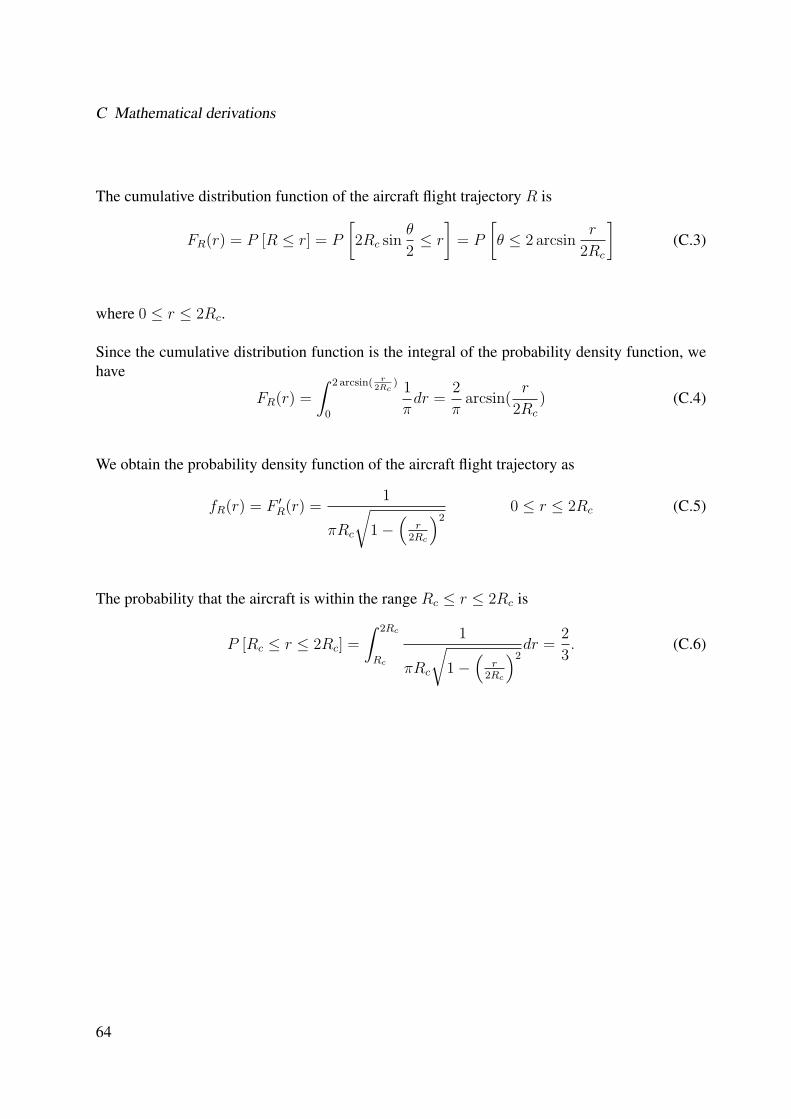
C Mathematical derivations
The cumulative distribution function of the aircraft flight trajectory R is
FR(r) = P [R ≤ r] = P
[2Rc sin
θ
2≤ r
]= P
[θ ≤ 2 arcsin
r
2Rc
](C.3)
where 0 ≤ r ≤ 2Rc.
Since the cumulative distribution function is the integral of the probability density function, wehave
FR(r) =
∫ 2 arcsin( r2Rc
)
0
1
πdr =
2
πarcsin(
r
2Rc
) (C.4)
We obtain the probability density function of the aircraft flight trajectory as
fR(r) = F ′R(r) =
1
πRc
√1−
(r
2Rc
)20 ≤ r ≤ 2Rc (C.5)
The probability that the aircraft is within the range Rc ≤ r ≤ 2Rc is
P [Rc ≤ r ≤ 2Rc] =
∫ 2Rc
Rc
1
πRc
√1−
(r
2Rc
)2dr =
2
3. (C.6)
64
Bibliography
[1] "Base station (BS) radio transmission and reception (FDD)", 3GPP Technical Specifica-tion 25.104 available at http://www.3gpp.org/ftp/Specs/html-info/25101.htm
[2] "User Equipment (UE) radio transmission and reception (FDD)", 3GPP Technical Speci-fication 25.101 available at http://www.3gpp.org/ftp/Specs/html-info/25101.htm
[3] "Multiplexing and channel coding (FDD)", 3GPP Technical Specification 25.212 availableat http://www.3gpp.org/ftp/Specs/html-info/25212.htm
[4] "Spreading and modulation (FDD)", 3GPP Technical Specification 25.213 availabale athttp://www.3gpp.org/ftp/Specs/html-info/25213.htm
[5] "Physical channels and mapping of transport channels onto physical channels (FDD)",3GPP Technical Specification 25.211 available at http://www.3gpp.org/ftp/Specs/html-info/25211.htm
[6] "Physical layer - General description", 3GPP Technical Specification 25.201 available athttp://www.3gpp.org/ftp/Specs/html-info/25201.htm
[7] "Radio interface protocol architecture", 3GPP Technical Specification 25.301 available athttp://www.3gpp.org/ftp/Specs/html-info/25301.htm
[8] "UTRAN Iur interface general aspects and principles", 3GPP Technical Specification25.420 available at http://www.3gpp.org/ftp/Specs/html-info/25420.htm
[9] "AirCell readies direct air-to-ground WiFi for US flights", 26th April 2005, available atwww.cbronline.com
[10] "AirCell demonstrates in-flight wireless broadband using EVDO", 25th October 2005,available at www.evdoinfo.com
[11] "Voice and data up in the air", Glenn Fleishman, 15th November 2005,available atwww.mobilepipeline.com
[12] "Rival emerges to Boeing’s in-flight broadband", 23rd January 2006, available athttp://seattletimes.nwsource.com
[13] Radiation Pattern 3.0, Powerwave Technologies, available athttp://ww2.allgon.se/SYrp3/index.html
65
Bibliography
[14] "790-2500 MHz Base Station Antennas for Mobile Communications", Kathrein, availableat www.kathrein.de
[15] UMTS World antenna page: www.umtsworld.com/industry/antenna.htm
[16] UMTSlink, www.umtslink.at
[17] UMTS World, www.umtsworld.com
[18] "WCDMA for UMTS: Radio Access for Third Generation Mobile Communications",edited by Harry Holma and Antti Toskala, Nokia (Finland), 2000 John Wiley and Sons,Ltd.
[19] "UMTS and mobile computing", A. J. Huber and J. F. Huber, 2002 Artech House.
[20] "UMTS networks: architecture, mobility and services", H. Kaaranen et al., 2001 JohnWiley and Sons, Ltd.
[21] "Digital communications", John G. Proakis, 3rd edition,McGRAW-HILL internationaleditions
66