Feasibility of Surfactant-Free Supported Emulsion …...Feasibility of Surfactant-Free Supported...
30
Feasibility of Surfactant-Free Supported Emulsion Liquid Membrane Extraction Shih-Yao B. Hu, Jin Li, and John M. Wiencek* The University of Iowa Department of Chemical and Biochemical Engineering Running Title: Surfactant-Free SELM Extraction *Corresponding Author John M. Wiencek 4122 Seamans Center Iowa City, IA 52242-1527 [email protected] Voice: (319) 353-2377 FAX: (319) 335-1415 Hu, Li & Wiencek 1/1 https://ntrs.nasa.gov/search.jsp?R=20030016582 2020-04-09T16:52:08+00:00Z
Transcript of Feasibility of Surfactant-Free Supported Emulsion …...Feasibility of Surfactant-Free Supported...

Feasibility of Surfactant-Free Supported Emulsion Liquid
Membrane Extraction
Shih-Yao B. Hu, Jin Li, and John M. Wiencek*
The University of Iowa
Department of Chemical and Biochemical Engineering
Running Title: Surfactant-Free SELM Extraction
*Corresponding Author
John M. Wiencek
4122 Seamans Center
Iowa City, IA 52242-1527
Voice: (319) 353-2377
FAX: (319) 335-1415
Hu, Li & Wiencek 1/1
https://ntrs.nasa.gov/search.jsp?R=20030016582 2020-04-09T16:52:08+00:00Z
Abstract
Supported emulsion liquid membrane (SELM) is an effective means to conduct liquid-
liquid extraction. SELM extraction is particularly attractive for separation tasks in the
microgravity environment where density difference between the solvent and the internal phase of
the emulsion is inconsequential and a stable dispersion can be maintained without surfactant. In
this research, dispersed two-phase flow in SELM extraction is modeled using the Lagrangian
method. The results show that SELM extraction process in the microgravity environment can be
simulated on earth by matching the density of the solvent and the stripping phase. Feasibility of
surfactant-free SELM (SFSELM) extraction is assessed by studying the coalescence behavior of
the internal phase in the absence of the surfactant. Although the contacting area between the
solvent and the internal phase in SFSELM extraction is significantly less than the area provided
by regular emulsion due to drop coalescence, it is comparable to the area provided by a typical
hollow-fiber membrane. Thus, the stripping process is highly unlikely to become the rate-
limiting step in SFSELM extraction. SFSELM remains an effective way to achieve simultaneous
extraction and stripping and is able to eliminate the equilibrium limitation in the typical solvent
extraction processes. The SFSELM design is similar to the supported liquid membrane design in
some aspects.
Keywords" extraction, hollow fiber, emulsion, propionic acid, microgravity, liquid membrane,
surfactant.
Hu, Li & Wiencek 2/2

Introduction
Supported emulsion liquid membrane (SELM) extraction is an effective technique to
conduct liquid-liquid extraction. In a typical SELM extraction, a water-in-off emulsion liquid
membrane (ELM) is first formulated by dispersing an aqueous solution into an organic solvent.
The aqueous phase, stabilized by surfactant, forms numerous micro-droplets within the
continuous, organic phase. The emulsion is then brought into contact with an aqueous feed
stream via a microporous hollow-fiber membrane. The solute dissolves into the organic solvent,
then is transported to the surface of the internal aqueous droplets, and finally partitions into the
internal aqueous droplets. Because of the stripping mechanism provided by the internal phase,
the solute concentration in the organic solvent is maintained at a low level and a high extraction
efficiency can be sustained for a long period of time. The SELM design inherits all the benefits
of membrane-based extraction, namely dispersion-fi-ee operation and easy scale-up, while
eliminating the equilibrium limitation of common extraction process. SELM also minimizes the
leakage and swelling problems associated with dispersive ELM extractions. SELM has been
successfully used for the extraction of heavy metals and organics (1,2,3).
A tradeoffof SELM's high extraction capacity is that the ELM must be demulsified to
recover the product. Due to density differentials between the solvent and the internal phase,
surfactant is usuaUy required to maintain a stable dispersion. Demulsification may be achieved
chemicaUy or by heat treatment (4). Electrostatic coalescence has been used extensively for the
demulsification of coarse, water-in-oil emulsion industrially (5). Success has also been reported
on a membrane-based demulsification method (6).
Recently, the authors proposed the possibility of surfactant-free SELM (SFSELM)
extraction in the microgravity environment (7). Because the density differential will not result in
Hu, Li & Wiencek 3/3

phasesegregationin themicrogravityenvironment,astabledispersionof thestrippingphase
withinthesolventmaybemaintainedevenwithoutsurfactant.Thebenefitof SELMcanbe
realizedwithoutthedrawbackof thedemulsificationprocess.SFSELMextractionprovidesan
efficientwayformediarecycleandcanhavesignificantimpactonthesustainabilityof
bioreactorsaboardspacecrafts.Highground-to-orbitlaunchcostsaswellastheutility costsof
refrigerationfor storagemakesthemediarequirementquitesubstantialmspaceexperiments.
Purificationandreuseof complexmediaareneededforlongdurationcellcultureinouterspace.
Onearth,mediais typicallydiscardedafterasingleuse,whichusuallyleadsto expensive
wastewatertreatmentafterwards;therefore,it isalsobeneficialto recyclemediaonearthaswell.
SFSELMextractiononearthisalsopossibleif thedensitiesof thesolventandthestripping
phasearecloselymatched.
In thisresearch,thefeasibilityof SFSELMextractionisassessed.Theresearchconsists
of twopart. Thefirst partisaproof-of-conceptstudythatdealswith thedroplettrajectoryin
SFSELMextractionundervariousconditions.Besidesstabilizingtheimmiscibledispersionin
theemulsion,thepresenceofsurfactant also minimizes the size of the stripping phase droplets.
The free dispersion of emulsion provides enormous contacting area for the stripping step and
minimizes the mass transfer resistance. The main concern of SFSELM extraction is, thus, the
loss of contacting area due to the elimination of surfactant. The second part of the research
studies the effect of drop coalescence on the contacting area between the solvent and the internal
phase.
Hu, Li & Wiencek 4/4

Effect of Density Differentials on Drop Trajectory
SFSELM is basically a dispersed two-phase system. Analogies of the fluid mechanics in
SFSELM may be drawn from commonly used chemical process such as the bubble column and
the fluidized bed. Various approaches have been used to model such dispersed two-phase flow
systems. The most notable ones are the Eulerian method (8), the Algebraic Slip Mixture Model
(ASMM) (9), and the Lagrangian method (10). The Lagrangian method allows the tracking of
the trajectory of each particle and is used ihere. In the Lagrangian method, the carrier phase is
treated as a continuum and is subject to the mass, momentum and energy conservation equations.
The effect of the dispersed phase is coupled into these equations as source terms. Thus, the
continuity equation at steady state may be written in tensor notation as
a ou,)_+m (1)Oxj
where p is the density of the continuous phase and u is the velocity of the continuous phase. _m
is the source term that accounts for the mass exchange between the continuous phase and the
dispersed phase. The subscriptj indicates the spatial coordinates;j = 1, 2 and 3 corresponds to
the X, Yand Z direction respectively. Unlike in the case of bubble column reactor, mass
exchange between the solvent and the stripping phase is usually insignificant in liquid-liquid
SELM extraction and the source term is negligible; i.e. _m = 0. In addition, constant density
may be assumed for liquid flow. The continuity equation thus reduces to
aua = 0 (2)3xj
The equation of momentum conservation in the i direction at steady state may be written as
Hu, Li & Wiencek 5/5

wherep is the pressure and _: is the normal and shear stress and g is the gravitational
acceleration. The subscript i represent the X, Y or Z direction. _M is the source term
representing momentum transfer between the carrier phase and the dispersed phase, which is
typically the result of drag force. The system is assumed to be isothermal so the energy
conservation equation is neglected.
written as
(3)
For Newtonian flow of constant density, equation (3) may be
( au, "] Op O2u ,
P_x: u' ) = - ----- + # N--_ + Pg' +*_Ox, ax:
where # is the viscosity of the continuous phase. As the name suggests, the trajectory of the
dispersed phase is modeled using the Lagrangian approach on each droplet:
(4)
"- (5)
where u p, is the droplet velocity in the i direction and pP is the droplet density. X, the particle
relaxation time, is defined as
4pPD p2- (6)
3pCz_ Re p
where D p is the droplet diameter, CD is the drag coefficient and Re.° is the droplet Reynolds
number (Re p = (u-uP)iYp/#). Equation (6) is a simple momentum balance based on Newton's
second law of motion; the first term on the right-hand side is the drag force while the second
term contains the buoyancy and gravitational forces. The impact of the droplets on the
continuous phase is accounted for through the source term _M in equation (3) and (4). When the
Hu, Li & Wiencek 6/6

system'ismodelednumerically,thecomputationaldomainisdividedintoanarrayof small
controlvolumesandthesourcetermmaybecoupledintotheeachcontrolvolumeby
O,M(E)= 1 _ p p (u, u,;)
E k=!
where E denotes a control volume of interest, Vis the size of the control volume, nE is the
number of droplets within the control volume, k denotes a certain trajectory and _kis the number
ofch-oplets within the control volume that follow the same trajectory, Vp is the droplet volume,
and _tk is the residence time of droplets within the control volume that follow the trajectory k. A
particle is monitored as soon as it is introduced into the computational domain and the trajectory
of the particle may be obtained by integrating equation (5) from an initial location. An unsteady-
state simulation is also possible. However, tracking of the numerous droplets and trajectories is
computationally expensive and is beyond the scope of this study. The system is modeled using_
the commercial software package Fluent (Fluent, Inc., NH).
The simulations assume that the ELM flows through the lumen side of a hollow fiber
membrane. The conditions used were similar to previous experimental studies (1,7).
Specifically, the fiber lumen has a length of 24 cm and a diameter of 0.06 cm. Volumetric flow
rate through the fiber is 0.0196 cm3/sec and the volume fraction of the internal phase is 0.1. The
geometry of the model system has been reduced to two-dimensional space for simplicity. The
computational domain is a 24 cm x 0.06 cm rectangle that corresponds to the axial d_ection, x,
and the radial direction, R, in the fiber lumen. Typical diameter of a coarse emulsion droplet is 1
gm. The diameters of droplets in a surfactant-free dispersion of immiscible phase are
significantly larger. The drop size of such dispersion is commonly characterized by the Sauter
mean diameter. Correlations are available to estimate the Santer mean diameter by taking into
Hu, Li & Wiencek 7/7

accounttheinterfacialtension,viscosity,mixingspeed,thankandimpellerdiamters,andphase
ratio(11). Typically,thedropdiameterisapproximately0.01cm. If theinternaldroplets
disperseuniformly,thelengthfractionoccupiedbytheinternalphaseineachdimensionwill be
(0.1)1/3.Thus,thereareabout3droplets(0.06x(0.1)1/3+0.01=2.78)intheR direction at any
given axial location on average. In the simulation, the internal droplets are introduced into the
computational domain at 3 evenly spaced locations along the R direction at the inlet. The
velocity profile at the inlet is assumed to be laminar, which is typical in most HFC applications.
Specifically, u = 13.87-15410.79×r 2, where u is the velocity (cngsec) in the axial direction and r
is the radius (0 < r < 0.03 cm). The velocity of the droplets is assumed to be the same as velocity
of the adjacent continuous phase entering the computational domain. At the wall, the no-slip
boundary condition is invoked for the continuous phase. The model system uses n-tetradecane
and a mixture ofchlorobenzene and 1-octnol as the continuous phase and 1 N sodium hydroxide
as the dispersed phase. Density ofn-tetradecane, as measured by an Anton Paar DMA 500
Density Meter (Anton Paar, Valparaiso, IN), is 0.765 g/ml. A mixture of 81.62 wt. %
chlorobenzene and 18.38 wt. % 1-octanol has a density of 1.040 g/ml, which matches the density
of 1N sodium hydroxide solution. The viscosity ofn-tetradecane was measured to be 1.37 cP
using a Fisherbrand calibrated Ubbelohde viscometer. The viscosity of the chlorotSenzene
mixture is 1.047 cP.
Figure 1 shows the trajectories of water droplets in a water/n-tetradecane dispersion. The
HFC is horizontally mounted. The arrow right above the x-axis is used as a reference for the
velocity vectors and has a magnitude of 50 cm/sec. Due to the density difference between water
and n-tetradecane, the droplets quickly settle at the bottom of the fiber lumen. Note that the x-
axis is reduced by a scale of 0.001 so the figure can have a legible aspect ratio. Although the
Hu, Li & Wiencek 8/8

velocityvectorspointdownwardonlyslightly,thetrajectoriesfallrathersharply.Such
trajectoriessuggestthatthedropletswill accumulateinsidethefiberlumenandformslugs
eventually,andsignificantlyreducethecontactingareabetweenthesolventandthestripping
phase.
Figure2showsthetrajectoriesof waterdropletsinadensity-matching,chlorobenzene/n-
octanolmixture.Asexpected,thetrajectoriesof thedispersedphasefollowthestreamlinesof
thecontinuousphase.Noaccumulationof theinternalphaseis found.Figure2 wasobtainedby
settingtheHFCmodulehorizontallywiththegravitationforcein thenegativeR direction.
Changes in the mounting direction do not affect the outcome of the simulation. In fact, the exact
same figure may be obtained by using a water/n-tetradecane mixture (i.e. with density
differentials) with zero gravitational force. These results suggest that density-matching is a valid
way to simulate SFSELM process in the microgravity environment on earth. A result similar to
Figure 2 is obtained by using a water/n-tetradecane mixture with the HFC module vertically
mounted. The magnitude of the velocity vectors of the droplets will be slightly larger but remain
on the streamlines of the continuous phase. However, the geometry used in this simulation is
extremely simplified. In a real HFC module, the entrance and the exit to the hollow-fiber
membrane bundle usually have substantial change in geometry. These changes lead to irregular
restriction and expansion of the flow path. Our experimental observations in a similar geometry
show that, although the flow remain largely laminar, back-mixing becomes significant when
there is a density differential and the streamline and trajectories are no longer straight.
Hu, Li & Wiencek 9/9

Effect of Coalescence on the Internal Phase Surface Area
The previous section shows that density-matching is a valid way to simulate the
microgravity environment on earth. The most critical concern regarding SFSELM extraction
however, is whether the design can provide enough stripping capacity for effective extraction,
which depends mainly on the coalescence behavior of the internal phase. The breakage and
coalescence phenomenon in dispersed two-phase systems has been studied extensively
(12,13,14,15). Most studies in the literature concentrate on bubble column reactor or agitated
contactors. While many of the theories are applicable to SFSELM, flows in bubble column and
agitated contactor are mostly turbulent. On the other hand, flows in hoUow-fiber contactor are
largely laminar due to the small membrane diameter and slow flow rate. Thus, theories
developed for bubble columns and agitated contactors need to be selectively adopted and
modified to be applied to SFSELM. In turbulent flow, the energy is frequently strong enough to
cause drop breakage, which is unlikely in laminar dispersed flow. Mechanisms that result in
drop coalescence in turbulent flows include turbulence, buoyancy, and laminar shear (16). In
SFSELM, laminar shear is the only likely mechanism for coalescence, i.e., droplets in faster-
moving area catch up with droplets in slower-moving area and coalesce with them. Because the
flow is laminar, droplets will not collide due to the macro and micro mixing as in a turbulent
flow. Buoyancy is not a concern either because the densities are matched. The coalescence of
two droplets takes place in three steps: (1) initial contact of the two drops; (2) drainage and
thinning of the liquid film between the two drops; and (3) thickness of the liquid film reduces to
a critical level, breakage of the film occurs, and the drops coalesce (12). Step (1) is related to the
collision frequency of the drops, _. Collision alone does not guarantee the coalescence of two
droplets. Once a collision happens, the drops must remain in contact for a period of time for the
Hu, Li & Wiencek 10/10

drainageandruptureto occur.Thus,step(2)and(3)maybequantifiedbyacollision
"efficiency",e. The overall coalescence rate, F, can then be represented by (16)
=Cmoe o (8)
The subscript m and n denote the sizes of droplets involved in a coalescence event.
Simultaneous coalescence between three and more drops is highly unlikely and will not
considered here. In this approach, collision events are dictated by the collision frequency, _mn;
collision efficiency, emn, indicates whether coalescence occurred and is considered
independently. The collision frequency from laminar shear may be approximated by (17)
_mn =4NmNn(rm p -.[-FP) 3 -0ux (9)
where Pm and r_ are the radii of drops of size m and n, and Armand N_ are the population
14densities of drops of size m and n. The collision effÉciency, Emn,may expressed as
=exp(-amo/3 o) (10)
where am_ is the time required for coalescence, or coalescence time, and 3_ is the contacting
time between the droplets. The coalescence time can be calculated from 16
/ 3 -,1/2
=[r_-_p| lnho (11)
amo (160 )
where o-is the interfacial tension, ho is the irfitial film thickness, hfis the final film thickness at
which film rupture occurs, and the equivalent radius rmn is defined as
1(1 + 1 )-I (12)
Contact time in laminar flow is not readily available from the literature but can be easily
derived. Consider two droplets, A and B, in a two-dimensional space that depicts the lumen side
Hu, Li & Wiencek - 11/11

of ahollow-fibermembraneasshowninFigure3. Theflow isassumedto besymmetricalin the
radialdirectionandindependentof theangulardirectioninthecylindricalcoordinate.The
drops,separatedbyadistanceof ARin theR direction, are moving in the x-direction at different
speeds. The radii of the drops are r°,, and r_n. Collision occurs when (rPm+ho+Pn)sinO < AR
according to the definition from equation (8) to (12), which can be approximated by
(Pm+Pn)sin0 _<AR since h0 is relatively small. When the two drops collide, the contacting area
of both drops will deform, a liquid disk will form between the drops and the draining process
begins. As mentioned earlier, if the drops remain in contact long enough, the thickness of the
disk will decrease to a critical point, the film will rupture and the two drops merge into a single
drop. If the two drops do not coalesce, drop B would have catch up to drop A by a distance of
2(rP,,+/',).cos0 x/3m, during the contact time. Since AR = (P,,+Pn).sin0, the contacting time
between the two drops is
2cotO
/3ran= 0Ux (_ +rp ) (13)OR
The contacting time,/3,,,, will have a value of 0 when 0 is 90 ° (AR = Pm+rP,) and is infinite when
0 is 0 (AR = 0). Substituting equation (13) into equation (10); one gets
- --jtanvj (14)
¢,,,(0) will have a value of 1 when 0 = 0 and is 0 when 0 = _/2. The average value e,,, may be
obtained by
Hu, Li & Wiencek 12/12

2 r_/2 (0)d0=TJo (15)
The integration in equation (15) cannot be easily evaluated analytically. Thus, a numerical
method will be employed.
The general trend of coalescence efficiency is shown in Figure 4. The parameter _cmay
be considered as the combined effect of coalescence time and shear rate. When the value of _is
small, collision is effective _om most approaching angles. When _cis large, collision leads to
coalescence only when the approaching angle is small, when surfactant is used, the interfacial
tension o"in equation (11) is minimized. The time required for droplet coalescence, _n,
becomes extremely large. As a result, the value of _cis large and the collisions become very
inefficient. A high shear rate also decreases the collision efficiency by decreasing the contacting
time. However, the collision frequency in equation (9) will increase. Another factor that affects
the collision efficiency is the drop size; the larger the drops, the less likely that coalescence will
Occur.
To investigate the coalescence behavior of the droplets, a population balance must be
derived for the internal droplets. Consider an organic-aqueous mixture flowing through the
lumen side of a hollow fiber membrane. The membrane has an inner diameter of 2R0 and a
length of L. The flow is assumed to be symmetrical in the radial direction. A tube-shaped,
infinitesimal volume inside the fiber lumen can be defined as shown in Figure 5. Flow velocity
and droplet size distribution may be considered constant within this infinitesimal volume. The
population balance within this volume for a drop of size m may be written as
Hu, Li & Wiencek 13/13

n,nan- ' ndnIThe first and second terms in equation (16) represent the number of droplets entering and leaving
the control volume by convection. The first integration on the right-hand side is the rate of
formation of drops of size m by the coalescence of smaller drops per unit volume. The last term
accounts for the rate of disappearing of drops of size m due to coalescence. Steady state is
assumed so there is no accumulation term in the equation. Equation (16) may be written as an
ordinary differential equation
dNm
dx 1 [fo/2 F(,,_,)d n- loft, dn] (17)U x
with a boundary condition ofNm = N,, ° at the inlet. Note that Nm, us and F depend on R as well.
Because the flow velocity is zero in the radial direction, the population density in a "tube" as
shown in Figure 5 is independent of the population density in an adjacent tube theoretically. The
population density at a specific R thus depends only on the axial position x. Nm as a function ofx
and R can be obtained by integrating equation (17). Once Nm is available, the specific contacting
area between the internal phase and the solvent per unit volume may be calculated from
2 _o . )dRj° R (_ooNmamam (18)
where am is the surface area of a droplet of size m. A is a function ofx. Velocity prone of a
steady-state laminar flow inside a circular pipe is well known (18)
/]where ub is the bulk or average flow velocity in the tube.
Hu, Li & Wiencek 14/14
Thesimulationis implementedusingtheMatlabprogramminglanguage(The
MathWorks,Inc.,Natick,MA). To simplifythecalculation,alldropsenteringthehollow-fiber
membraneareassumedto havethesamediameterof 100gm. At 10%volumeratio,the
populationdensityof thesedropsis 1.91×10⁵drops/cm3. Populationdensitiesof dropletsof
varioussizesalongtheaxialdirectionaretrackedbyintegratingequation(17). In thelasttwo
termsof equation(17),collisioneventsbetweenallpossibledropletsizecombinationsmustbe
evaluated.Thenumberof dropletsizesthatneedsto betrackedincreasestwofoldwitheach
iterationwhilethenumberof collision events that needs to be tracked increases exponentially. It
is unrealistic to carry out such simulation beyond several iterations. It is obvious that some
reasonable assumption needs to be implemented to make such calculations practical. Drops
having an N less than 17.7 cm -3, the inverse of the volume of the fiber lumen, are not utilized to
calculate subsequent collision events. Because the population density of these drops is already
low, the probability that these drops participate in collision events is also low.
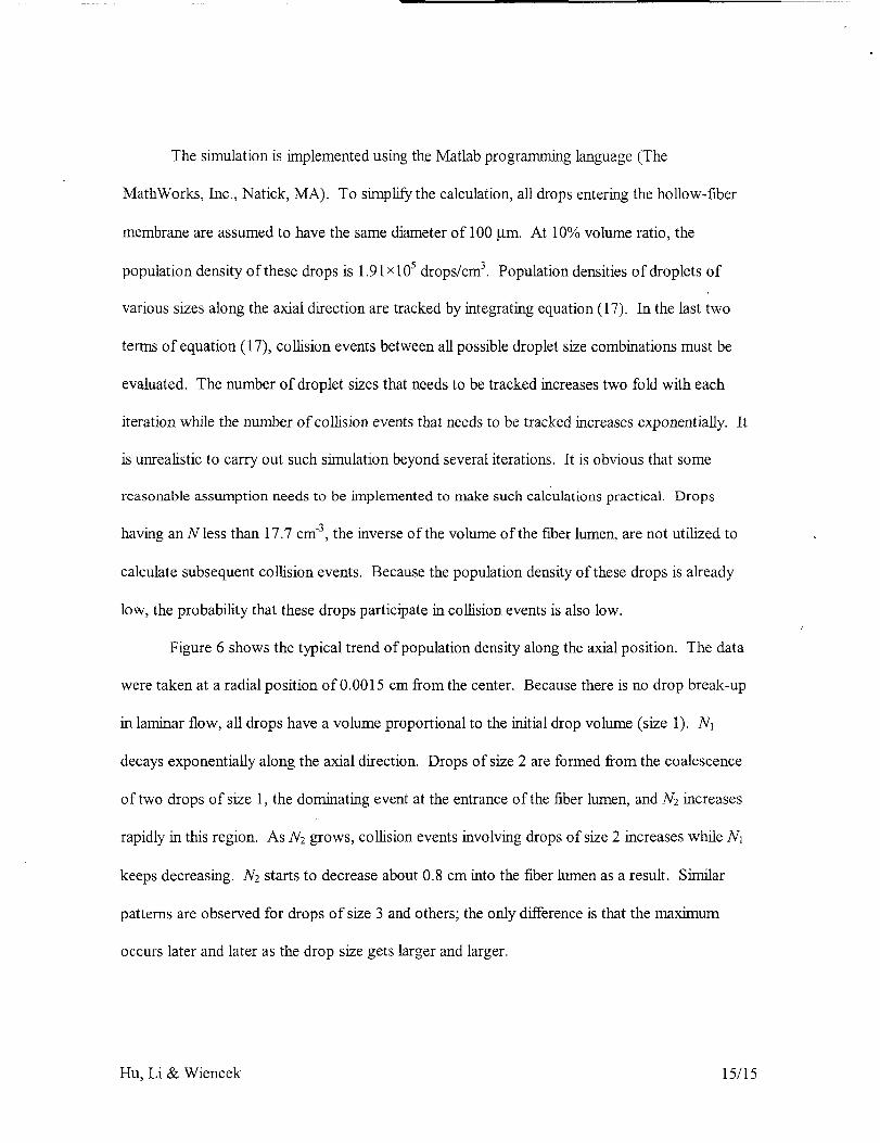
Figure 6 shows the typical trend of population density along the axial position. The data
were taken at a radial position of 0.0015 cm from the center. Because there is no drop break-up
in laminar flow, all drops have a volume proportional to the initial drop volume (size 1). N1
decays exponentially along the axial direction. Drops of size 2 are formed from the coalescence
of two drops of size 1, the dominating event at the entrance of the fiber lumen, and Nz increases
rapidly in this region. As N2 grows, collision events involving drops of size 2 increases while N1
keeps decreasing. N2 starts to decrease about 0.8 cm into the fiber lumen as a result. Similar
patterns are observed for drops of size 3 and others; the only difference is that the maximum
occurs later and later as the drop size gets larger and larger.
Hu, Li & Wiencek 15/15

Figure7 showsthattheshearratehasasignificantimpacton thecoalescencerate. The
five linesinFigure7 indicatethechangesinN1 at five different radial position in the tube. A
laminar flow in a circular tube has parabolic velocity distribution as indicated by equation (19).
The shear rate is zero at the center and reaches the maximum at the wall. As discussed earlier, a
high shear rate decreases the contacting time and thus decreases the collision efficiency. On the
other hand, high shear rate results in high collision frequency as well. Since coalescence rate is
the product of collision rate and collision efficiency, the net effect of high shear rate on the
coalescence rate could be either positive or negative. In Figure 7, the closer the drops is to the
wall, the faster they coalescence. Such responses suggest that collision rate is the dominating
effect on coalescence in this case. A closer inspection reveals that the collision efficiency of
drops of size 1 is about 0.995 at all radial position at the entrance. This means when two drops
collide, they almost always coalesce. This is mostly due to the high interfacial tension between
the internal phase and the solvent. As a result, coalescence rate depends mainly on collision rate
and coalescence rate increases as the shear rate increase.
Figure 8 shows the changes in specific contacting area, the contacting area between the
solvent and the internal phase per unit volume ofmLxture, along the axial position. The specific
contacting area decreases dramatically after the mixture enters the tube. This is mainly due to
the high coalescence rate of drops of size 1. Assuming spherical geometry, several smaller drops
always provide larger surface area than a single large drop at the same total volume. The
decrease in specific contacting area shown in Figure 8 is even faster than the decrease in
population density of drops of size 1 shown in Figure 6. This is because the total surface area is
proportional to the square of total drop number. After a few centimeters, the specific contacting
area stabilizes at around 12.7 cm2/cm 3. The average value throughout the fiber lumen is 13.03
Hu, Li & Wiencek 16/16

cma/cm3. Typicaldiameterof coarseemulsiondropletisabout1gm. At avolumefraction
(internalphase/emulsion)of 0.1,therewill be1.91x1011dropletspermilliliterof emulsion,
whichprovideaspecificcontactingareaof 6000cm2/cm3. Thisnumberissignificantlylarger
thanthe 13.03cm2/cm3obtainedfromSFSELM.Ontheotherhand,withouttakingporosityin
to account,thefiberlumenprovidesaspecificcontactingareaof only66.7cm2/cm3. Oncethe
porosityis takenintoaccount,thespecificareaprovidedbythehollow-fibermembraneshould
becomparableor lessthanthatprovidedbySFSELMbecauseextractioncanonlyhappenatthe
poreopenings.Thethicknessof thehollow-fibermembraneisalsosignificantlylargerthanthe
thicknessof theboundarylayersurroundingthestrippingphasedroplets.In addition,the
partitioncoefficientin theextractionstepis typicallylowdueto toxicityconsiderationswhen
selectingthesolvent(7). Thestrippingstep,ontheotherhand,alwayshasapartitioncoefficient
thathighlyfavorsthestrippingphase.All thesefactorswill contributeto theoverallmass
transferresistancein thehollow-fibermembrane.Thus,thestrippingprocessintheSFSELM
designisunlikelyto becomearate-limitingstepof theextractionprocess.In theworstcase
scenario,theSFSELMdesignsimplybecomesthesameasthesupportedliquidmembrane
(SLM)design(19). However,lossof solventdueto its solubilityinwaterisamajorconcernin
SLMextraction.20TheSFSELMdesignwill nothavethisproblembecausethesolventis
constantlyreplenishedto themembranepores.In short,SFSELMisafeasiblewayto conduct
solventextractionwithsimultaneousstrippingfor extractiontasksin themicrogravity
environment.
Hu,Li & Wiencek 17/17

Summary
The feasibility of SFSELM extraction was assessed in this research. SF'SELM extraction
was conceived as a mean to conduct extractive fermentation in the microgravity environment.
Due to the absence of the gravitational force, a stable water-in-oil dispersion can be maintained
without the use of surfactant. Such a design preserves the advantages of SELM extraction,
namely eliminating the equilibrium constraint of solvent extraction and stable operation, while
simpli_ing the product recovery process because no demulsification is necessary. Trajectories
of the dispersed phase in a SFSELM flow was studied using the Lagrangian method. Effects of
density differential between the two phases, HFC module orientation, and gravitational force
were examined. It was found that matching the density of the two phases has the same effect of
zero gravity. The result suggests that SFSELM extraction in the microgravity environment can
be simulated by matching the density of the internal phase and the solvent. One shortcoming of
SFSELM is the reduced contacting area between the solvent and the internal phase, which may
limit the stripping efficiency. In addition, drop coalescence becomes a significant phenomenon
because the interfacial tension is no longer minimized without surfactant. In a SFSELM flow,
the main mechanism of drop coalescence is laminar shear, i.e. drops in the faster-flowing region
catch up to drops in the slower flowing region and collide. The coalescence phenomenon is
studied by taking into account of collision frequency and collision efficiency. It was found that,
without surfactant, the collision efficiency is nearly 100% in a typical SFSELM flow. Collision
frequency is the dominant effect that determines the coalescence rate. Coalescence is most
prominent in regions where velocity gradient is large, such as near the wall in a laminar flow.
Nevertheless, the contacting area between the internal phase and the solvent is comparable to the
area for extraction offered by the hollow-fiber membrane. Thus, the SFSELM design should be
Hu, Li & Wiencek 18/18

ableto sustainthestrippingprocess,providinganefficientwayto conductsolventextractionand
simplifyingthedownstreamproductrecoveryprocessi themicrogravityenvironment.
Acknowledgement
The authors would like to thank NASA for the funding of this project.
List of Symbols
A
a
c_D
E
g
ho, hf
L
n
N
P
R
r
Ro
Re
rm,
t
U
V
X
xj
Specific contacting area between the solvent and the internal phase, cm2/cm 3
Surface area of a single internal phase droplet
Drag coefficient
Particle or drop diameter, cm
Designate a control volume of interest
Gravitational acceleration, crrds 2
Initial and final film thickness during coalescence, cm
Fiber length
Number of droplets
PopulaUon density of the internal phase droplets, 1/cm 3
Pressure, dyne/cm 2
Radial direction within the membrane lumen, cm
Radius of an internal phase droplet
Radius of the fiber lumen, cm
Reynolds number
Equivalent radius, cm
Time, s
Flow or particle velocity, cm/s
Volume, cm 3
Axial direction inside the fiber lumen, cm
xl, x2, x3, represent x, y and z respectively, cm
Greek
F
(X
&
¢77
K"
Z
#0
P
Letters
Source term in the governing equations; _m is the mass source (g/cm 3 s) and _M is the momentum source
(dyne/cm 3)
Coalescence rate, 1/cm 3-s
Coalescence time, s
Contacting time, s
Residence time of droplets within a control volume
Collision efficiency
Collision frequency, 1/cm 3-s
Number of droplets within a control volume
Combined effect of coalescence time and shear rate
Particle relaxation time, s
Viscosity, g/cm.s
Approaching angle during drop collisions
Density, g/cm 3
Hu, Li & Wiencek 19/19

o"
"c
Interracial tension, dyne/cm 2
Normal and shear stress, dyne/cm 2
Superscripts and Subscripts
b Bulk or average property inside the fiber lumen
E Property within the control volume E
i,j Direction in the Cartesian coordinate; i orj = 1, 2 and 3 corresponds to the X,Y and Z direction
respectively.
k Property of a specific drop trajectory
m, n Designate drop of certain sizes. Analytically, m and n can range from 0 to infimte. In the numerical
simulation, m and n represent how many times a drop Is larger than drops at the entrance All drops at the
entrance have a size of 1. m = 121, for example means a drop is 121 time larger volume-wise than the
drops at the entrance
p Property of an internal phase droplet
Hu, Li & Wiencek 20/20

References
1 Hu, S B. and Wiencek, J. M., AIChEJ. 44, 570, 1998.
2 Breembroek, G. R. M., van Straalen, A., Witkamp, G. J. and van Rosmalen, G. M., J. Membr. Sci. 146, 185, 1998.
3 Nanoti, A., Ganguly, S. K., Goswarni, A. N. and Rawat, B. S., Ind. Eng. Chem. Res. 36, 4369, 1997.
4 Lissant, K., Demulsification - Industrial Applications, in Surfactant Science Series, Vol. 13,1992.
5J. Draxler, J., Furst, W. and Marr, R., Separation of Metal Species by Emulsion Liquid Membrane, J. Membr. Sci.
38, 281, 1988.
6 Yirmizi, N. P., Raghuraman, B. and Wiencek, J., Demulsification of water/oil/solid emulsions by hollow-fiber
membranes, AIChEJ. 42, 1263, 1996.
7 Li, J., Hu, S. B. and Wiencek, J. M., Development of a Supported Emulsion Liquid Membrane System for
Proplonic Acid Separation in a Microgravity Environment, Biotechnol. Bioprocess Eng. 6, 4261, 2001.
8 Anderson, T. B. and Jackson, R., A fluld dynamical description of fluidized beds, Ind. Eng. Chem. Fundam. 6,
527, 1967.
9 Manninen, M, Taivassalo, V. and Kallio, S., On the Mixture Model for Multiphase Flow, VIT Publications,
Technical Research Centre of Finland, 1996.
10 Migdal, D. and Agosta, D., A Source Flow Model for Continuum Gas-Particle Flow, Trans. ASME, J. Appl.
Mech. 34E,, 1967.
11 Skelland, A. and Lee, J., Drop Size and Continuous-Phase Mass Transfer in Agitated Vessels, AIChE J. 27, 99,
1981.
12 Valentas, K. J. and Amundson, N. R., Breakage and Coalescence in Dispersed Phase Systems, I&EC Fund 5,
533, 1966.
13 Ktrkpatrick, R. D. and Lockett, M., The Influence of Approach Velocity on Bubble Coalescence, Chem. Eng. Sci.
29, 2363, 1974.
14 Coulaloglou, C. and Tavlarides, L. L., Description of Interaction Processes in Agltated Liquid-Liquid
Dispersions, Chem. Eng. Scz 32, 1289, 1977
15 Millies, M. and Mewes, D., Interfacial area density in bubbly flow, Chem. Eng Process. 38, 307, 1999.
16 Prince, M. J. and Blanch, H. W., Bubble Coalescence and Break-Up in Air-Sparged Bubble Columns, AIChE J.
36, 1485, 1990
17 Friedlander, S. K., in Smoke, Dust, andHaze, 2ndEd., pp.200, 2000.
18 Bird, R. B., Stewart, W. E. and Lightfoot, E. N., Transport Phenomena, John Wdey & Son, 1960.
19 Ward, W. J. and Robb, W. L., Carbon Dloxlde-Oxygen Separation: Facilitated Transport of Carbon Dioxide
across a Liquid Film, Science 156, 1481, 1967.
20 Danesi, P. R., Yinger, R. and Rickert, P. G., Lifetime of Supported Liquid Membranes: The Influence of
Interracial Properties, Chemical Composition and Water Transport on the Long-Term Stability of the
Membrane, J. Membr. Sci, 31, 117, 1987.
Hu, Li & Wiencek 21/21

Figure Captions
Figure l. Trajectories of water droplets in n-tetradecane in a horizontally momated HFC.
Figure 2. Trajectory of water droplets in a density-matching mixture.
Figure 3. Derive contacting time between droplets in laminar flow.
Figure 4. Effect of coalescence time and shear rate on collision efficiency.
Figure 5. An infinitesimal, tube-shaped geometry in the fiber lumen is used for population
balance of the internal phase.
Figure 6. Population densities of drops of size 1, 2 and 3 at a radius of 0.0015 cm.
Figure 7. Population densities of drop of size 1 at various axial and radial positions.
Figure 8. Specific contacting area between solvent and the internal phase in SFSELM
Hu, Li & Wiencek 22/22

Figure 1. Trajectories of water droplets in n-tetradecane in a horizontally mounted HFC.
0.03 ]
0.02
N
E 0.01- ',,O
,.- \N
O 'x--_
"--m 0 _ \0 \
_. \'\
-0.01 - \,'_----_ \,\r,_ _ _ \,7__::_,,.-
', \
\
-0.02 _ '--
*, \.,r__._"
C _ ',-0.03 _ '- .... : --
/ 50 cm/seci
0.020 0.004 0.008 0.012 0.016
Axial Position xl0 -3 (cm)
Hu, Li & Wiencek 23/23

Figure 2. Trajectory of water droplets in a density-matching mixture.
0.02
E 0.01r..3
c-o
"_ 00
13..
-o -0.0103
r_
-0.02
-0.0350 cm/sec
0
I
0.004 0.008 0.012 0.016
Axial Position xl0 -3 (cm)
Hu, Li & Wiencek 24/24

Figure 3. Derive contacting time between droplets in laminar flow.
.... ---ilR- ...... -_ ux
R
_U x+_.AR
_R
Hu, Li & Wiencek
25/25

Figure 4. Effect of coalescence time and shear rate on collision efficiency.
1.2
1.0
0.8
0.6
0.4
0.2
0.0
0 I 0
A : 0.01
0.2 0.4 0.6 0.8 1.0 1.2 1.4 1.6 1.8 2.0
0
Hu, Li & Wiencek 26/26

Figure 5. An infinitesimal, tube-shaped geometry in the fiber lumen is used for population balance of the
internal phase.
Fiber Wall, R = R o
x=O
,%Nm/x,R
x=L
Fiber Wall, R = R o
x x+Ax
Hu, Li & Wiencek 27/27

Figure 6. Population densities of drops of size 1, 2 and 3 at a radius of 0.0015 cm.
18
_- 16
E14
Q.0I--
D 12
g 10¢--(D
D 8EO
°--,,i,,,,o
O13..
xlO 4
Size 1
Size 2
Size 3
6
4
[,...,...
i ",\
0 6 12 18 24
Axial Position (cm)
Hu, Li & Wiencek 28/28

Figure 7. Population densities of drop of size 1 at various axial and radial positions.
18
16d
E 1400Q.o_- 12
"l:J
10if}c-
a 8t-O:,= 663
4Orl
2
x 10 4
.......... °
X "x
0
"''4.
"4 ___
"--------m.
0.2 0.4 0.6 0.8 1
Axial Position (cm)
Hu, Li & Wiencek 29/29

Figure8. SpecificcontactingareabetweensolventandtheinternalphaseinSFSELM
6O
v
40<131c"
30O
c"O
O 20O
o10
o3
0
\,
I I I
0 6 12
Axial Position (cm)
18 24
Hu, Li & Wiencek 30/30


![Open Droplets: Programming chemical ow in micro uidics€¦ · 1 Introduction An emulsion is the dispersion of one uid into an-other, stabilised by surfactant molecules [2, 3]. Emul-sions](https://static.fdocuments.net/doc/165x107/5ecdddae2bb9fa1fcc69f235/open-droplets-programming-chemical-ow-in-micro-uidics-1-introduction-an-emulsion.jpg)