FEA Analysis of Novel Design of Cylindrical Roller Bearing
48
Cleveland State University Cleveland State University EngagedScholarship@CSU EngagedScholarship@CSU ETD Archive 2011 FEA Analysis of Novel Design of Cylindrical Roller Bearing FEA Analysis of Novel Design of Cylindrical Roller Bearing Prasanna Subbarao Bhamidipati Cleveland State University Follow this and additional works at: https://engagedscholarship.csuohio.edu/etdarchive Part of the Mechanical Engineering Commons How does access to this work benefit you? Let us know! How does access to this work benefit you? Let us know! Recommended Citation Recommended Citation Bhamidipati, Prasanna Subbarao, "FEA Analysis of Novel Design of Cylindrical Roller Bearing" (2011). ETD Archive. 629. https://engagedscholarship.csuohio.edu/etdarchive/629 This Thesis is brought to you for free and open access by EngagedScholarship@CSU. It has been accepted for inclusion in ETD Archive by an authorized administrator of EngagedScholarship@CSU. For more information, please contact [email protected].
Transcript of FEA Analysis of Novel Design of Cylindrical Roller Bearing
Cleveland State University Cleveland State University
EngagedScholarship@CSU EngagedScholarship@CSU
ETD Archive
2011
FEA Analysis of Novel Design of Cylindrical Roller Bearing FEA Analysis of Novel Design of Cylindrical Roller Bearing
Prasanna Subbarao Bhamidipati Cleveland State University
Follow this and additional works at: https://engagedscholarship.csuohio.edu/etdarchive
Part of the Mechanical Engineering Commons
How does access to this work benefit you? Let us know! How does access to this work benefit you? Let us know!
Recommended Citation Recommended Citation Bhamidipati, Prasanna Subbarao, "FEA Analysis of Novel Design of Cylindrical Roller Bearing" (2011). ETD Archive. 629. https://engagedscholarship.csuohio.edu/etdarchive/629
This Thesis is brought to you for free and open access by EngagedScholarship@CSU. It has been accepted for inclusion in ETD Archive by an authorized administrator of EngagedScholarship@CSU. For more information, please contact [email protected].
FEA ANALYSIS OF NOVEL DESIGN OF CYLINDRICAL ROLLER
BEARING
PRASANNA SUBBARAO BHAMIDIPATI
Bachelor of Science in Mechanical engineering
R.C.E, affiliated to Jawaharlal Nehru technological university
Hyderabad, India
May, 2006
submitted in partial fulfillment of requirements for the degree
MASTER OF SCIENCE IN MECHANICAL ENGINEERING
at the
CLEVELAND STATE UNIVERSITY
December 2011
This thesis has been approved
for the Department of MECHANICAL ENGINEERING
And the College of Graduate Studies by
________________________________________________________________________
Thesis Committee Chairperson, Dr. Majid Rashidi
________________________________________________________________________
Department, Date
Dr. Rama S.R. Gorla
________________________________________________________________________
Department, Date
Dr. Asuquo Ebiana
________________________________________________________________________
Department, Date
DEDICATED TO……..
To my parent and my brother who made my
life possible and encouraged me in all the
stages in my life
“Sharma Bhamidipati”
“Naga Lakshmi Bhamidipati”
“Sai Uday Bhamidipati”
To my uncle‟s family who made me
believe that “I can do it” and for the
continues support to my family
“Subrahmanyam V.V.R.S and family”
To my fiancée for her continuous support and
understanding
“ Apoorva Balantrapu”
To entire teaching staff of Mechanical
engineering department at Cleveland
state university for all support
“C.S.U -Mechanical Engineering
Department ”
ACKNOWLEDGEMENT
First, I would like to express my sincere gratitude to my advisor Dr. Majid Rashidi for
his guidance, support and patience throughout this work. I have benefited a lot from his
knowledge, insight and commitment towards helping his students and I would like to
thank for all his guidance in my study. This would have been not possible without Dr.
Majid Rashidi support and help.
I also would like to thank Dr. Rama S.R. Gorla, Dr. Asuquo Ebiana for being a part of
thesis committee and for taking time to review my thesis.
I want to take this opportunity to thank entire department of Mechanical
Engineering at Cleveland State University for all the support and special thanks to Dr.
William Atherton M.E, chairman for all valuable suggestions.
On top of all, I owe a particular debt of gratitude and appreciation to my family for their
consistent encouragement and advice through my life.
V
FEA ANALYSIS OF NOVEL DESIGN OF CYLINDRICAL ROLLER
BEARING
PRASANNA SUBBARAO BHAMIDIPATI
ABSTRACT
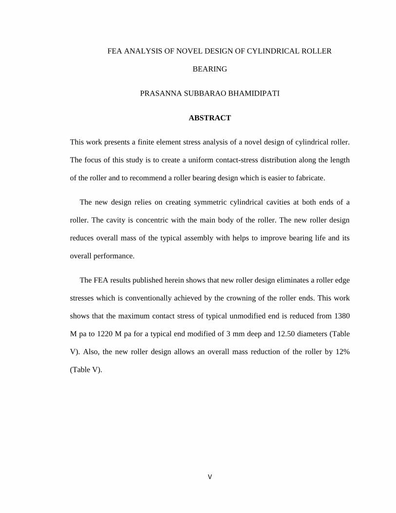
This work presents a finite element stress analysis of a novel design of cylindrical roller.
The focus of this study is to create a uniform contact-stress distribution along the length
of the roller and to recommend a roller bearing design which is easier to fabricate.
The new design relies on creating symmetric cylindrical cavities at both ends of a
roller. The cavity is concentric with the main body of the roller. The new roller design
reduces overall mass of the typical assembly with helps to improve bearing life and its
overall performance.
The FEA results published herein shows that new roller design eliminates a roller edge
stresses which is conventionally achieved by the crowning of the roller ends. This work
shows that the maximum contact stress of typical unmodified end is reduced from 1380
M pa to 1220 M pa for a typical end modified of 3 mm deep and 12.50 diameters (Table
V). Also, the new roller design allows an overall mass reduction of the roller by 12%
(Table V).
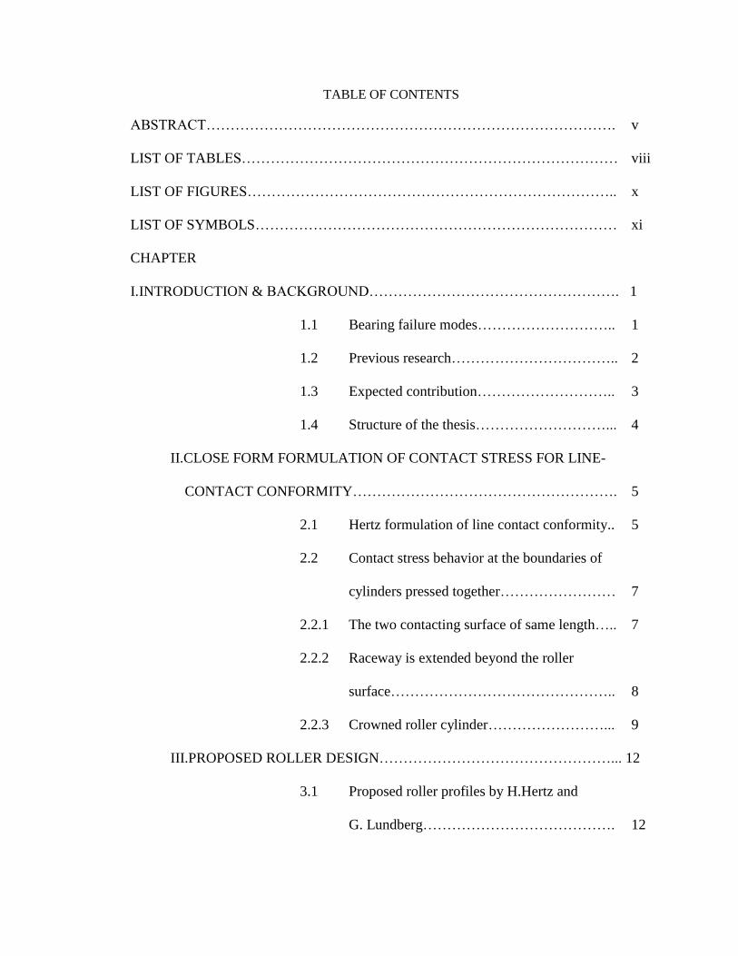
TABLE OF CONTENTS
ABSTRACT…………………………………………………………………………. v
LIST OF TABLES…………………………………………………………………… viii
LIST OF FIGURES………………………………………………………………….. x
LIST OF SYMBOLS………………………………………………………………… xi
CHAPTER
I.INTRODUCTION & BACKGROUND……………………………………………. 1
1.1 Bearing failure modes……………………….. 1
1.2 Previous research…………………………….. 2
1.3 Expected contribution……………………….. 3
1.4 Structure of the thesis………………………... 4
II.CLOSE FORM FORMULATION OF CONTACT STRESS FOR LINE-
CONTACT CONFORMITY……………………………………………….
5
2.1 Hertz formulation of line contact conformity.. 5
2.2 Contact stress behavior at the boundaries of
cylinders pressed together……………………
7
2.2.1 The two contacting surface of same length….. 7
2.2.2 Raceway is extended beyond the roller
surface………………………………………..
8
2.2.3 Crowned roller cylinder……………………... 9
III.PROPOSED ROLLER DESIGN…………………………………………... 12
3.1 Proposed roller profiles by H.Hertz and
G. Lundberg………………………………….
12
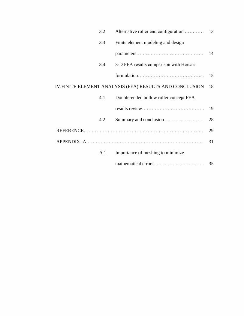
3.2 Alternative roller end configuration ………… 13
3.3 Finite element modeling and design
parameters……………………………………
14
3.4 3-D FEA results comparison with Hertz‟s
formulation…………………………………...
15
IV.FINITE ELEMENT ANALYSIS (FEA) RESULTS AND CONCLUSION 18
4.1 Double-ended hollow roller concept FEA
results review…………………………………
19
4.2 Summary and conclusion……………………. 28
REFERENCE………………………………………………………………… 29
APPENDIX -A……………………………………………………………….. 31
A.1 Importance of meshing to minimize
mathematical errors…………………………..
35
viii
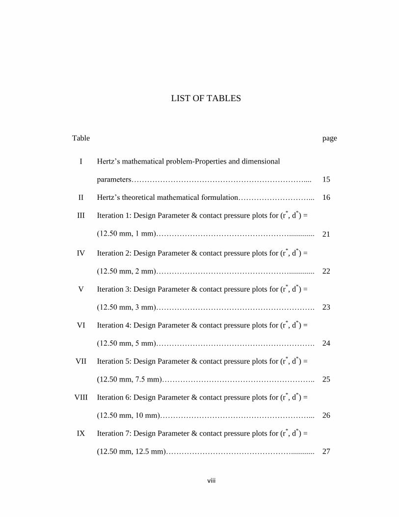
LIST OF TABLES
Table page
I Hertz‟s mathematical problem-Properties and dimensional
parameters…………………………………………………………....
15
II Hertz‟s theoretical mathematical formulation………………………... 16
III Iteration 1: Design Parameter & contact pressure plots for (r*, d
*) =
(12.50 mm, 1 mm)…………………………………………….............
21
IV Iteration 2: Design Parameter & contact pressure plots for (r*, d
*) =
(12.50 mm, 2 mm)…………………………………………….............
22
V Iteration 3: Design Parameter & contact pressure plots for (r*, d
*) =
(12.50 mm, 3 mm)…………………………………………………….
23
VI Iteration 4: Design Parameter & contact pressure plots for (r*, d
*) =
(12.50 mm, 5 mm)…………………………………………………….
24
VII Iteration 5: Design Parameter & contact pressure plots for (r*, d
*) =
(12.50 mm, 7.5 mm)…………………………………………………..
25
VIII Iteration 6: Design Parameter & contact pressure plots for (r*, d
*) =
(12.50 mm, 10 mm)…………………………………………………...
26
IX Iteration 7: Design Parameter & contact pressure plots for (r*, d
*) =
(12.50 mm, 12.5 mm)…………………………………………............
27
ix
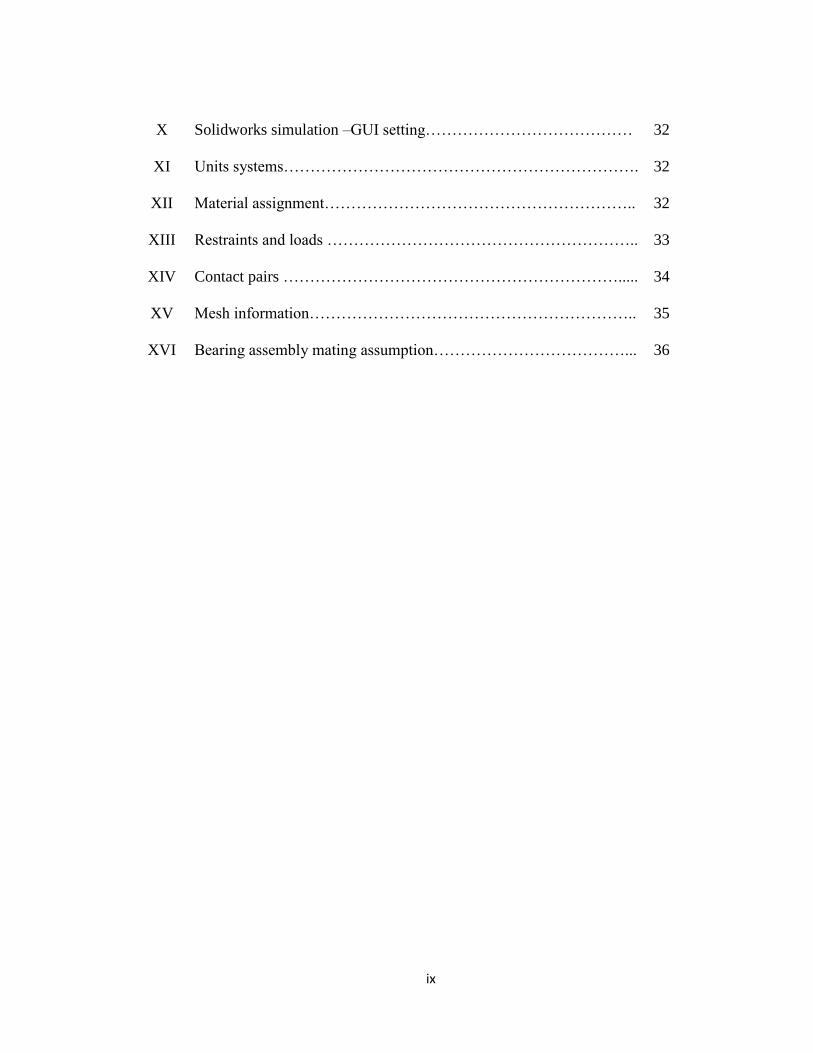
X Solidworks simulation –GUI setting………………………………… 32
XI Units systems…………………………………………………………. 32
XII Material assignment………………………………………………….. 32
XIII Restraints and loads ………………………………………………….. 33
XIV Contact pairs ………………………………………………………..... 34
XV Mesh information…………………………………………………….. 35
XVI Bearing assembly mating assumption………………………………... 36
x
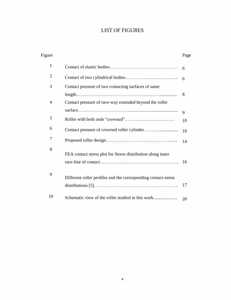
LIST OF FIGURES
Figure Page
1 Contact of elastic bodies……………………………………… 6
2 Contact of two cylindrical bodies…………………………….. 6
3 Contact pressure of two contacting surfaces of same
length……………………………………………….................
8
4 Contact pressure of race-way extended beyond the roller
surface………………………………........................................
9
5 Roller with both ends “crowned”…………………………… 10
6 Contact pressure of crowned roller cylinder……….................. 10
7 Proposed roller design………………………………………... 14
8 FEA contact stress plot for Stress distribution along inner
race-line of contact…………………………………………….
16
9 Different roller profiles and the corresponding contact-stress
distributions [5]………………………………………………..
17
10 Schematic view of the roller studied in this work..................... 20
xi
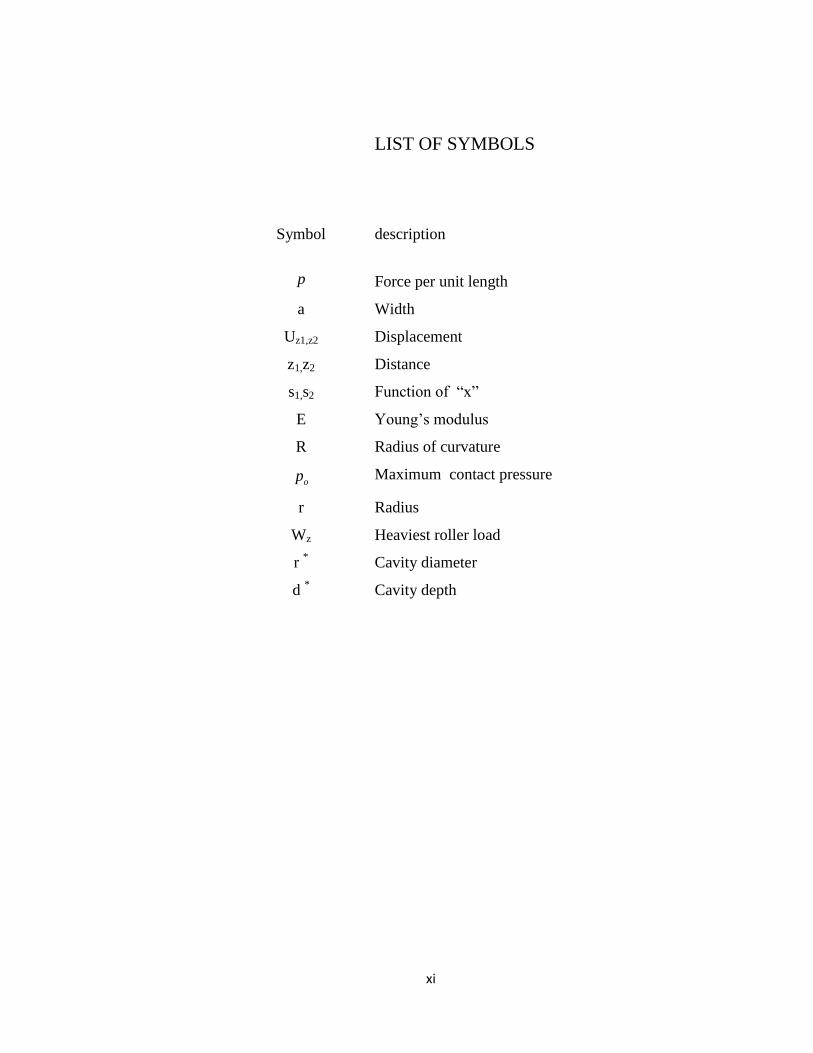
LIST OF SYMBOLS
Symbol description
p Force per unit length
a Width
Uz1,z2 Displacement
z1,z2 Distance
s1,s2 Function of “x”
E Young‟s modulus
R Radius of curvature
op Maximum contact pressure
r Radius
Wz Heaviest roller load
r *
Cavity diameter
d *
Cavity depth
1
CHAPTER I
INTRODUCTION & BACKGROUND
1.1 Bearing failure modes:
When a bearing is properly designed, manufactured, installed, and maintained, then
the natural cause of bearing failure is typically the fatigue life of its rolling elements and
races. The environment within which the bearing operates also determines the bearing
life.
The contact stresses developed in the rolling elements and races of a typical bearing is
cyclic in nature. This in turn will result in a potential fatigue failure for these elements.
The fatigue life a bearing is influenced by the operating speed, load conditions, bearing
material, clearance of the mating parts, contact surface geometry, and the environment in
which the bearing operates.
2
The fatigue failure modes, mentioned above, could be categorized according the
following list:
Rolling element surface fatigue
Common wears of the interacting surfaces (races and rollers)
Cross-sectional cracking and fretting.
The cross-sectional cracking and fretting could be caused by unusual and/or abnormal
operating conditions that were not considered during the bearing design. Excessive
“hoop-stresses”, caused by centrifugal forces, could lead to race-way fractures [Zaretsky
and Loe, 1987].
1.2 Previous research:
It has been a common practice for many decades to utilize cylindrical shaped
roller bearing elements in machinery in order to evenly distribute the bearing load across
the line contact between the rollers and race-ways. However, designing a bearing such
that a uniform contact stress distribution is resulted along the contact lines of a roller
bearing is highly unrealistic. This difficulty stems from the fact that the two ends of a
typical roller act as stress-concentration zones, causing the contact stresses to have spikes
at the roller end points. The conventional method of rectifying this undesirable condition
is to modify the geometric configuration of the ends of the roller in a way that a sharp or
abrupt transition from the contact line to the cross-section of the roller is avoided. This
geometric modification is called “crowning” of the roller. Figure 9, show contrasts
between an unmodified and a crowned roller respectively, with their corresponding
contact stress distributions.
3
A substantial amount of research work has been done to study structural integrity
and behavior of cylindrical rolling elements, which have been crucial parts of a typical
bearing from contact stress point of view. Many researchers and designers have
developed various analytical, numerical, and experimental techniques in order to predict
and improve contact stress distributions along the contact line of rolling element
bearings. For, example Dareing and Zimovsly [1964] proposed analytical techniques in
order to computationally predict the contact stress distribution along the contact line of a
rolling element that is not crowed. Hardnett ,Kannel [1981], and Heydave and Goohar
[1979] included nonlinear behavior of the contacting surfaces under stress and came up
with an analytical solution to better predict the stress distribution at the contact line.
With the advent of various advanced FEA codes, and fast computational
hardware, the inherent difficulties of solving nonlinear FEA problem have been
addressed and resolve to a great extend.
In this research, Solidworks Simulation was used as the FEA solver importing parametric
models from Solidworks.
1.3 Expected contribution:
Empirical and real-world applications of roller element bearings have shown that
if the crowned geometry is not accurate, the uniform stress distribution may not be
realized. In other words, eliminating the contact stress spikes at the ends of a typical
roller becomes highly sensitive to manufacturing tolerances and accuracies. Thus the
bearing life and its performance largely depend upon the manufacturing accuracy of the
rollers.
4
In this thesis an innovative alternative approach for elimination or minimizing the
stress spikes at the ends of a typical roller is studies. This alternative roller
manufacturing approach will require less effort, especially in terms of keeping close
tolerances. Chapter 3 of this document describes this alternative method.
1.4 Structure of the thesis:
The structure of this thesis is as follows. In Chapter 2, Illustrates Hertz‟s [2] close-form
formulation for solving contact stress and Response of different cross-sectional roller end
conditions under load is described.
In chapter 3, proposed roller design and design parameter is described and 3-D
Finite element analysis (FEA) simulation of a roller-inner/outer race contact stress is
summarized briefly and its results are compared with Hertz‟s [2] in-line contact
formulations. In chapter 4, FEA for proposed roller design, the procedure and results are
reported. Further, research contributions and future research topics are summarized.
Finally, Appendix 1 is documented which describes geometrical, parametric settings and
all the assumptions consider for this research work.
5
CHAPTER II
CLOSE-FORM FORMULATION OF CONTACT STRESS FOR
LINE-CONTACT CONFORMITY
2.1 Hertz Formulation for Line-Contact Conformity:
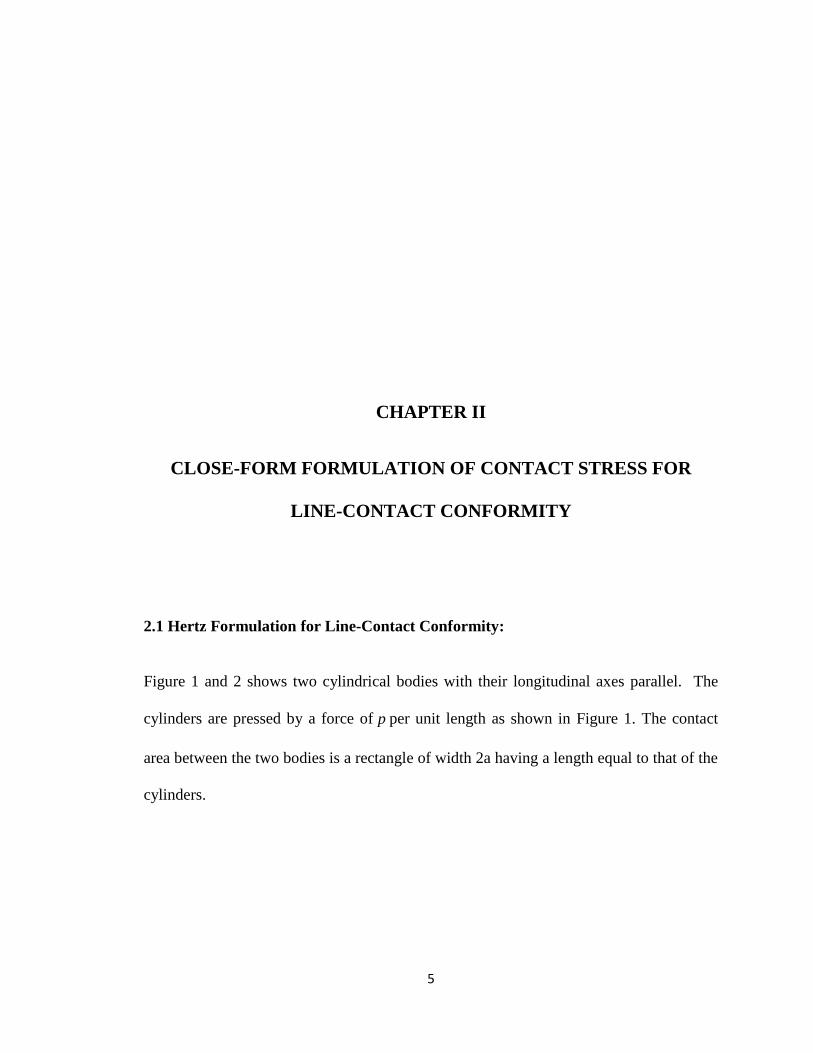
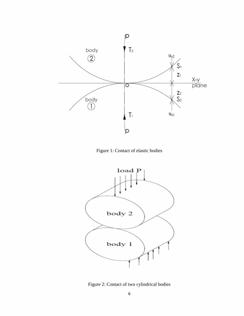
Figure 1 and 2 shows two cylindrical bodies with their longitudinal axes parallel. The
cylinders are pressed by a force of p per unit length as shown in Figure 1. The contact
area between the two bodies is a rectangle of width 2a having a length equal to that of the
cylinders.
6
Figure 1: Contact of elastic bodies
Figure 2: Contact of two cylindrical bodies
7
Therefore for the consistent pressure distribution, the pressure should sum-up to
R
Eap
4
*2 (2.1) and
*
2 4
E
pRa
,
2
122
2
2)( xa
a
pxp
And )(xp falls to zero at the edge of the contact.
The maximum pressure is
2
1
*
R
pEpo (2.2)
2.2 Contact stress behavior at the boundaries of cylinders pressed together:
The contact stress at the end points of two cylinders pressed together exhibits stress
concentration behavior. In order to avoid these stress concentration points in a typical
roller bearing, the axial profile of the roller is modified from a straight cylindrical shape
to a barrel shape configuration. This geometric modification results in eliminating or
minimizing the stress concentration at the ends of the rollers. The different possible
modified end conditions that yield a fairly uniform contact stress in discussed below.
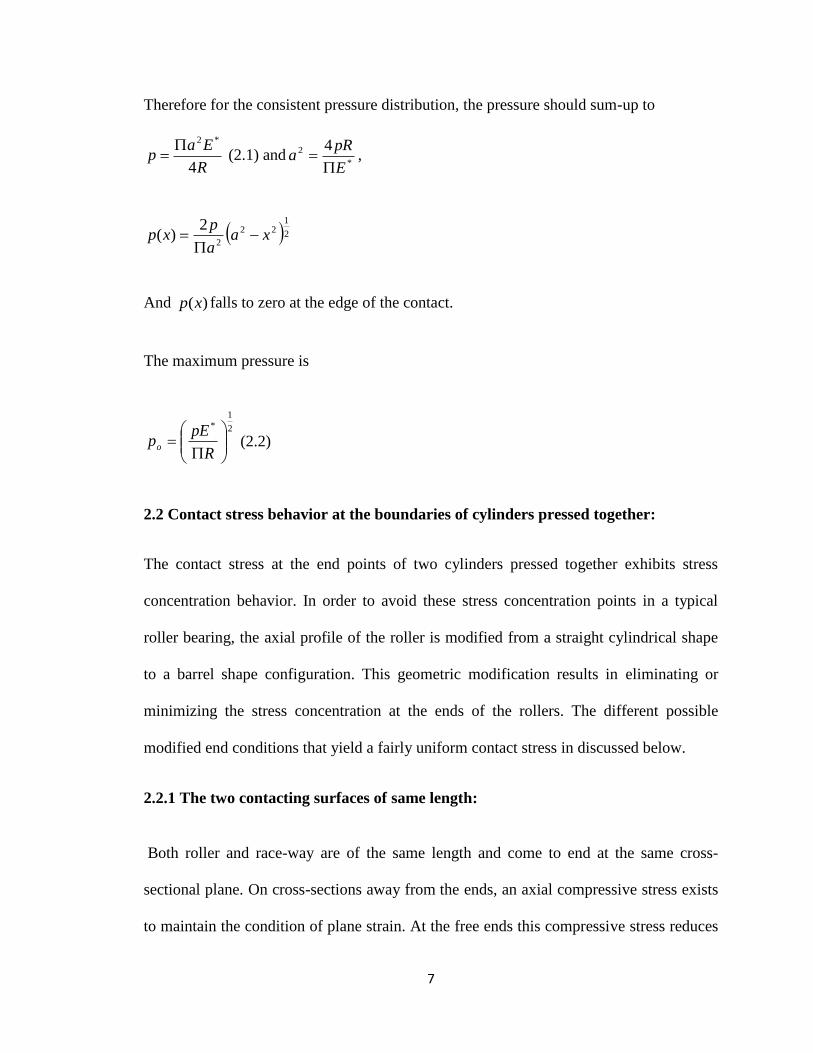
2.2.1 The two contacting surfaces of same length:
Both roller and race-way are of the same length and come to end at the same cross-
sectional plane. On cross-sections away from the ends, an axial compressive stress exists
to maintain the condition of plane strain. At the free ends this compressive stress reduces
8
in value, allowing the solids to expand slightly in the axial direction and thereby reducing
the contact pressure at the end as shown in Figure 3. An estimate of the reduction in the
pressure at the end of the roller may be obtained by assuming that the end of cylinder is
under a state of plane stress.
Figure 3: Contact pressure of two contacting surfaces of same length
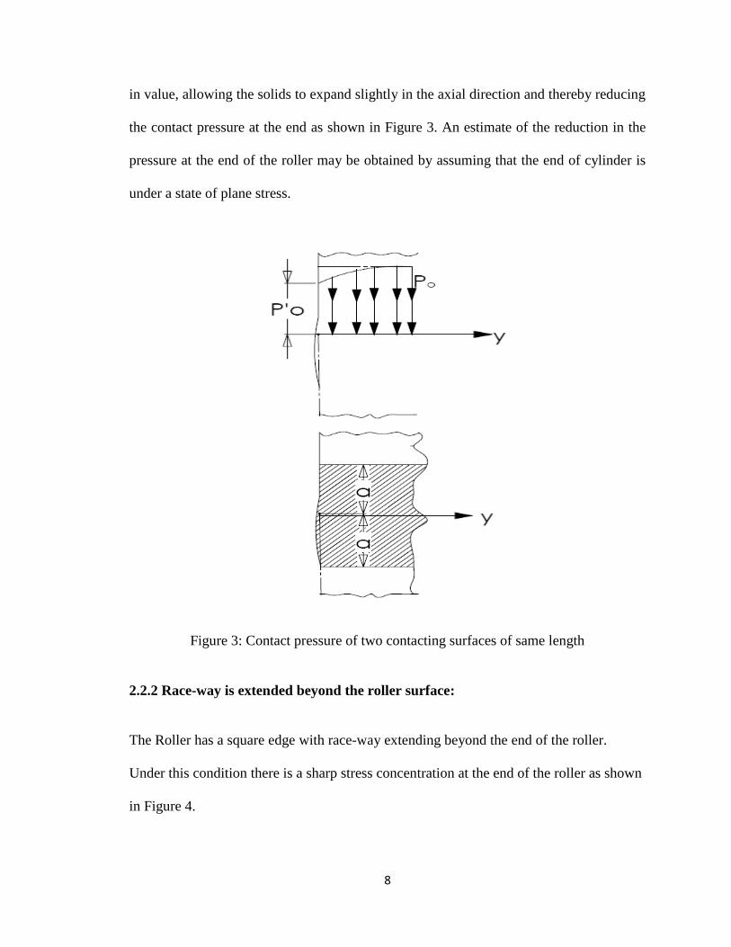
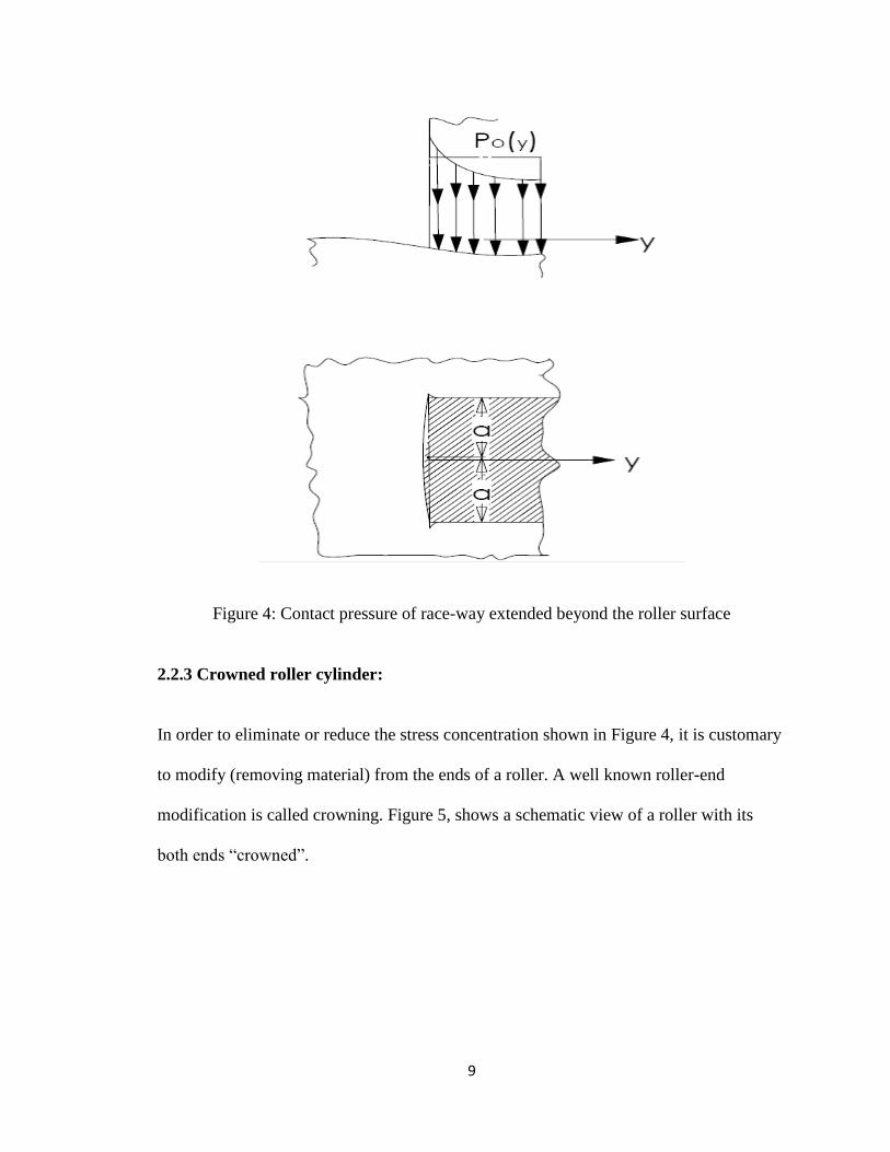
2.2.2 Race-way is extended beyond the roller surface:
The Roller has a square edge with race-way extending beyond the end of the roller.
Under this condition there is a sharp stress concentration at the end of the roller as shown
in Figure 4.
9
Figure 4: Contact pressure of race-way extended beyond the roller surface
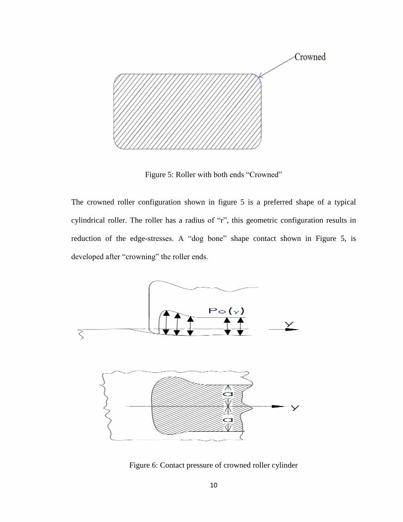
2.2.3 Crowned roller cylinder:
In order to eliminate or reduce the stress concentration shown in Figure 4, it is customary
to modify (removing material) from the ends of a roller. A well known roller-end
modification is called crowning. Figure 5, shows a schematic view of a roller with its
both ends “crowned”.
10
Figure 5: Roller with both ends “Crowned”
The crowned roller configuration shown in figure 5 is a preferred shape of a typical
cylindrical roller. The roller has a radius of “r”, this geometric configuration results in
reduction of the edge-stresses. A “dog bone” shape contact shown in Figure 5, is
developed after “crowning” the roller ends.
Figure 6: Contact pressure of crowned roller cylinder

11
In next chapter, an alternative modification for the geometric configuration of a typical
roller is proposed. Subsequently a 3-D FEA simulation of a roller-inner/outer race
contact stress is discussed briefly.
12
CHAPTER III
PROPOSED ROLLER DESIGN
3.1 Proposed roller profiles by H.Hertz and G.Lundberg:
During the past few decades the design of cylindrical roller bearings has been
significantly improved. These improvements are mainly achieved by advancement in
bearing steel materials and geometric design improvements. The design enchantments are
mostly focused on contact stress reduction at the bearing rolling contact regions. It has
been shown [1] that bearing life is inversely proportional to the stress raised to the ninth
power or even higher. For this reason significant efforts have been put in for solving
extensive range of contact problems [2-4].
It was recognized from theoretical formulation proposed by H.Hertz [8] and G. Lundberg
theory [1], as well as from laboratory tests [5], that changes by a few micrometers to the
13
profile of the roller has a significant effect on the bearing life. A concrete theoretical
relationship between roller profile and bearing life was never known; even to this date
such theoretical relationships have not been successfully established. The optimum
geometry of the roller profile modifications has been established more or less by trial-
and-error or by empirical approaches.
The circular arc profile, commonly known as crowning, resulted from the
Hertzian theory, whereas the cylindrically crowned profiles is a straight central portion
with crowned edges which was based on the Lundbery theory [1].
Use of these two methods of profile modifications resulted in considerable
progress to identify relative accuracy of edge profiles necessary to sustain uniform
contact stress distribution across the roller length.
However, theoretical relationships between a roller profile and bearing load-carrying
capacity for a given operating conditions have not been successfully established. After
many years of research, logarithmic [5] profile for cylindrical roller bearing was
proposed but the logarithmic profiles was mostly confined to the research and
engineering applications due to precise manufacturing requirement.
3.2 Alternative roller end configuration:
This thesis examines a novel roller design as shown in Figure 7, which offers many
advantages when compared to Logarithmic, Crowning, or cylindrical-crowned rollers
profiles.

14
Figure 7: Proposed roller design
The research conducted in this thesis also focused on designs which are more responsive
to varying bearing loads and which has lesser manufacturing restrictions. Also the design
concept studied in this work will reduce overall mass of the bearing, thus reducing the
centrifugal force acting on the outer-race, which could also contribute to an increase in
the bearing life.
3.3 Finite Element Modeling and Design Parameters:
Finite Element analysis was done to study the contact stresses developed in a typical
roller as shown in Figure 9 (a). Solidworks simulation Software is used to simulate to
realistic boundary and load conditions as described in Appendix-A.
The rest of this chapter describes FEA study of non-crowned roller bearing profile under
load and then results are compared with Hertz formulation (Equation 2.2).
15
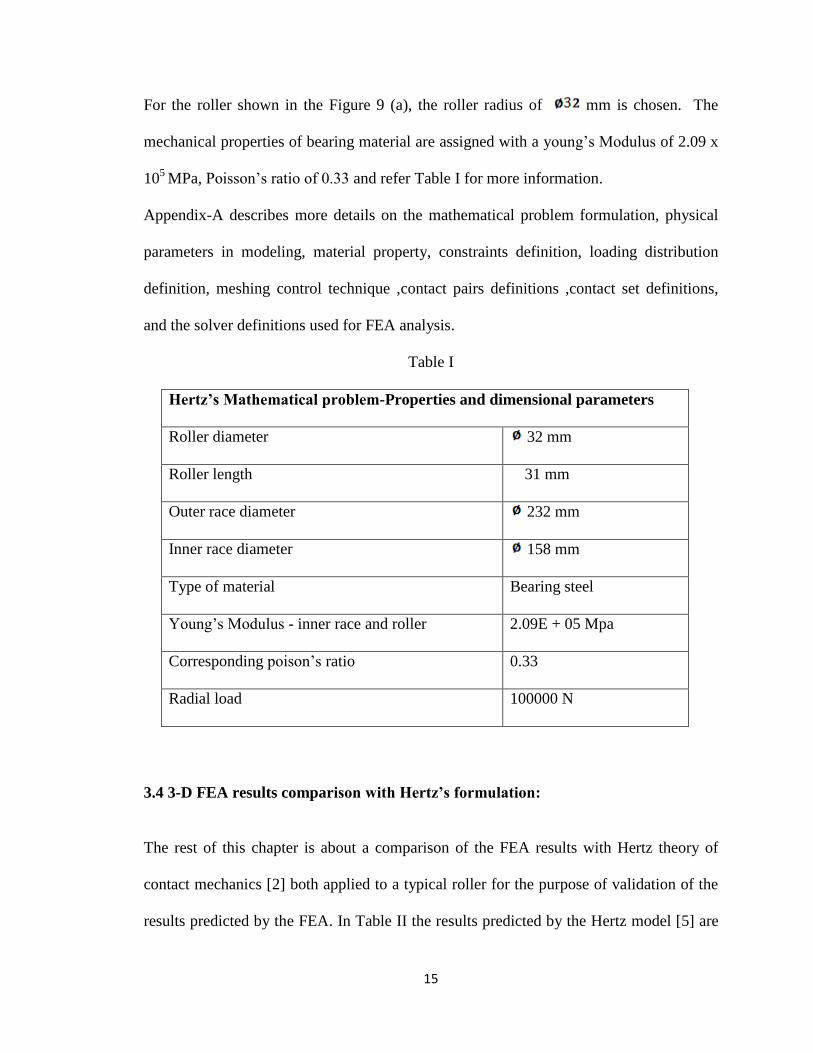
For the roller shown in the Figure 9 (a), the roller radius of mm is chosen. The
mechanical properties of bearing material are assigned with a young‟s Modulus of 2.09 x
105
MPa, Poisson‟s ratio of 0.33 and refer Table I for more information.
Appendix-A describes more details on the mathematical problem formulation, physical
parameters in modeling, material property, constraints definition, loading distribution
definition, meshing control technique ,contact pairs definitions ,contact set definitions,
and the solver definitions used for FEA analysis.
Table I
Hertz’s Mathematical problem-Properties and dimensional parameters
Roller diameter 32 mm
Roller length 31 mm
Outer race diameter 232 mm
Inner race diameter 158 mm
Type of material Bearing steel
Young‟s Modulus - inner race and roller 2.09E + 05 Mpa
Corresponding poison‟s ratio 0.33
Radial load 100000 N
3.4 3-D FEA results comparison with Hertz’s formulation:
The rest of this chapter is about a comparison of the FEA results with Hertz theory of
contact mechanics [2] both applied to a typical roller for the purpose of validation of the
results predicted by the FEA. In Table II the results predicted by the Hertz model [5] are

16
compared with FEA results, which show that FEA Results matches with Hertz theoretical
calculation with 3.2% Percentage error.
Table II
Hertz’s Theory Mathematical formulation
w(N) 100000
Rx(meters) 0.013
l(meters) 0.031
Hertz contact stress 2.94E+09 Mpa
FEA result 2.85E+09 Mpa
percentage error 3.2
Figure 8: FEA contact stress plot for Stress distribution along roller line of contact
17
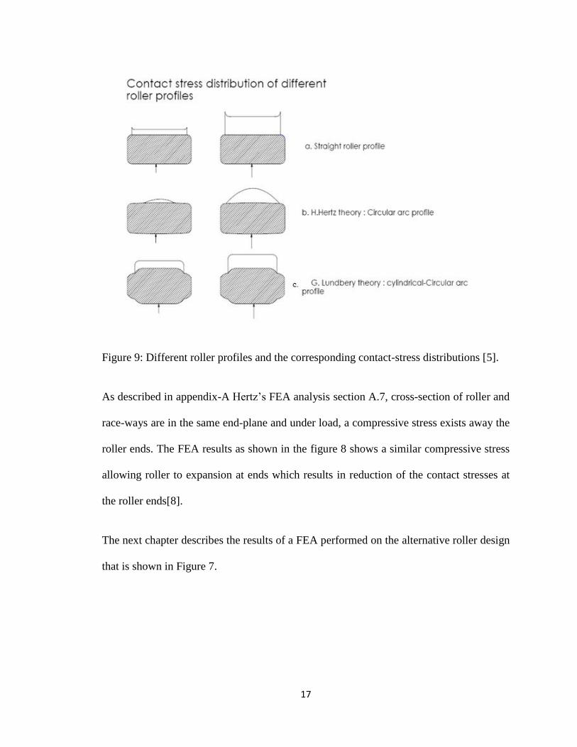
Figure 9: Different roller profiles and the corresponding contact-stress distributions [5].
As described in appendix-A Hertz‟s FEA analysis section A.7, cross-section of roller and
race-ways are in the same end-plane and under load, a compressive stress exists away the
roller ends. The FEA results as shown in the figure 8 shows a similar compressive stress
allowing roller to expansion at ends which results in reduction of the contact stresses at
the roller ends[8].
The next chapter describes the results of a FEA performed on the alternative roller design
that is shown in Figure 7.
18
CHAPTER IV
FINITE ELEMENT ANALYSIS, RESULTS AND CONCLUSION
The previous efforts to establish a uniform contact-stress distribution along the length of
a typical cylindrical roller was mainly focused on changing the roller profile and utilizing
advanced bearing steels materials. This work however takes a different approach by
studying of a novel roller end configuration that results in reduced roller stiffness at its
ends in the radial direction.
This research explore a new roller shape to provide a relatively uniform contact stress
distribution along the length of a roller by reducing the contact stiffness of the roller in
the radial direction of the roller‟s transverse cross-section. The approach relies on a
novel double-ended hollow roller design which has straight profile with end-cavities at
the two ends of the roller. Figure 10 shows a schematic view of the roller studied in this
work.
19
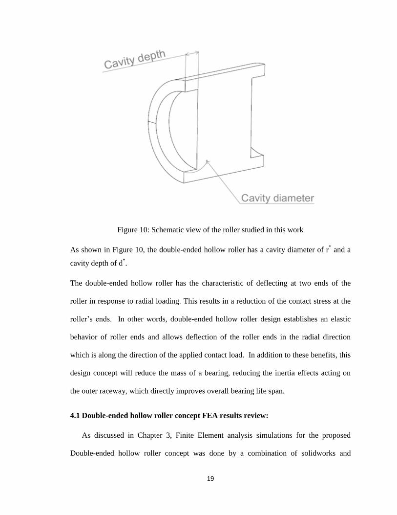
Figure 10: Schematic view of the roller studied in this work
As shown in Figure 10, the double-ended hollow roller has a cavity diameter of r* and a
cavity depth of d*.
The double-ended hollow roller has the characteristic of deflecting at two ends of the
roller in response to radial loading. This results in a reduction of the contact stress at the
roller‟s ends. In other words, double-ended hollow roller design establishes an elastic
behavior of roller ends and allows deflection of the roller ends in the radial direction
which is along the direction of the applied contact load. In addition to these benefits, this
design concept will reduce the mass of a bearing, reducing the inertia effects acting on
the outer raceway, which directly improves overall bearing life span.
4.1 Double-ended hollow roller concept FEA results review:
As discussed in Chapter 3, Finite Element analysis simulations for the proposed
Double-ended hollow roller concept was done by a combination of solidworks and
20
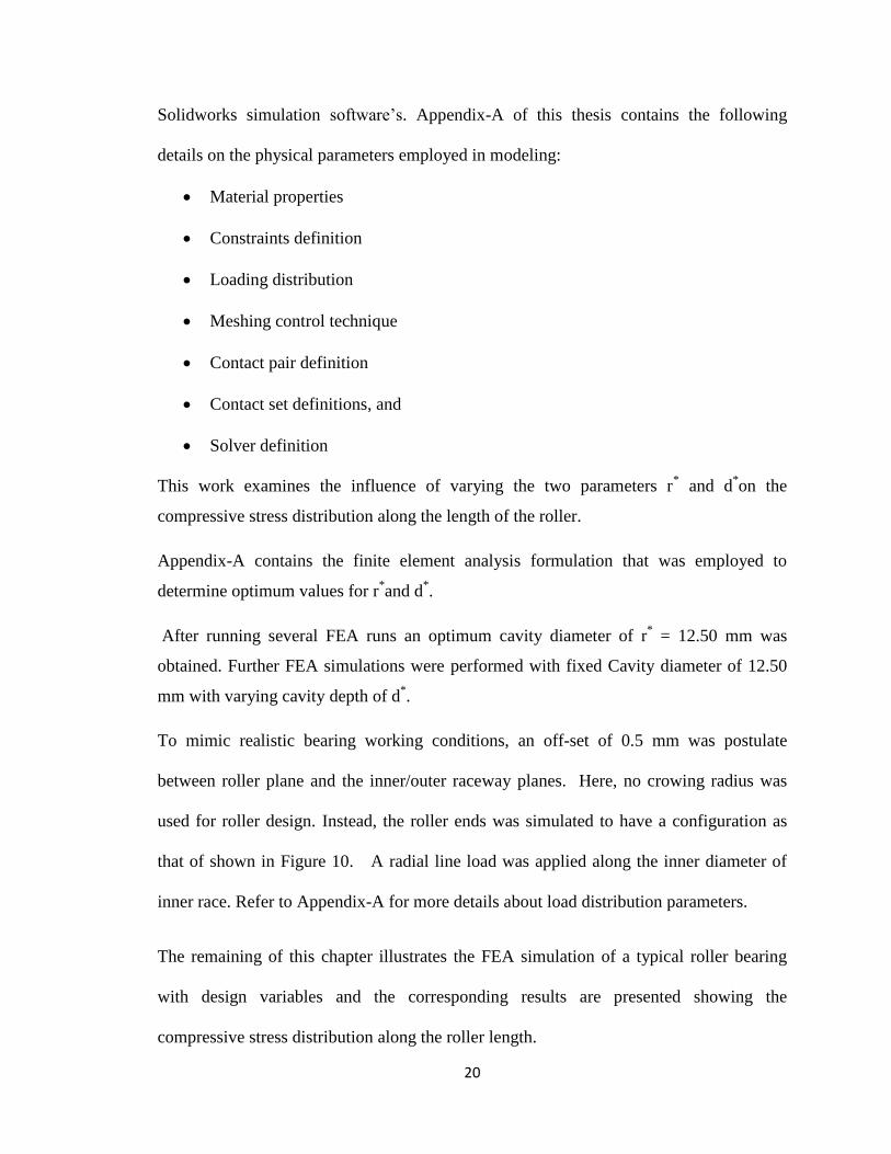
Solidworks simulation software‟s. Appendix-A of this thesis contains the following
details on the physical parameters employed in modeling:
Material properties
Constraints definition
Loading distribution
Meshing control technique
Contact pair definition
Contact set definitions, and
Solver definition
This work examines the influence of varying the two parameters r* and d
*on the
compressive stress distribution along the length of the roller.
Appendix-A contains the finite element analysis formulation that was employed to
determine optimum values for r*and d
*.
After running several FEA runs an optimum cavity diameter of r* = 12.50 mm was
obtained. Further FEA simulations were performed with fixed Cavity diameter of 12.50
mm with varying cavity depth of d*.
To mimic realistic bearing working conditions, an off-set of 0.5 mm was postulate
between roller plane and the inner/outer raceway planes. Here, no crowing radius was
used for roller design. Instead, the roller ends was simulated to have a configuration as
that of shown in Figure 10. A radial line load was applied along the inner diameter of
inner race. Refer to Appendix-A for more details about load distribution parameters.
The remaining of this chapter illustrates the FEA simulation of a typical roller bearing
with design variables and the corresponding results are presented showing the
compressive stress distribution along the roller length.
21
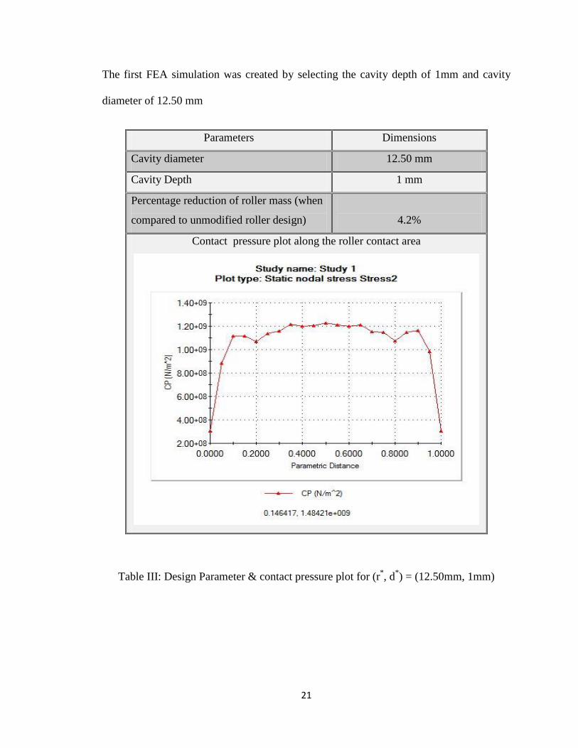
The first FEA simulation was created by selecting the cavity depth of 1mm and cavity
diameter of 12.50 mm
Parameters Dimensions
Cavity diameter 12.50 mm
Cavity Depth 1 mm
Percentage reduction of roller mass (when
compared to unmodified roller design)
4.2%
Contact pressure plot along the roller contact area
Table III: Design Parameter & contact pressure plot for (r*, d
*) = (12.50mm, 1mm)
22
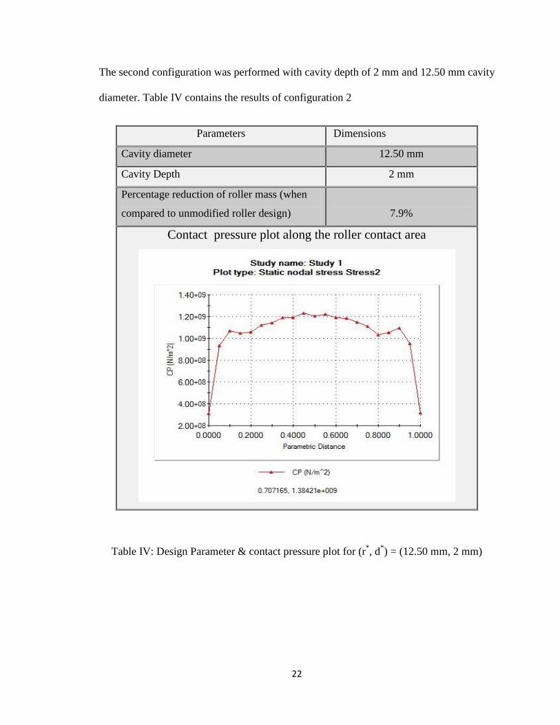
The second configuration was performed with cavity depth of 2 mm and 12.50 mm cavity
diameter. Table IV contains the results of configuration 2
Parameters Dimensions
Cavity diameter 12.50 mm
Cavity Depth 2 mm
Percentage reduction of roller mass (when
compared to unmodified roller design)
7.9%
Contact pressure plot along the roller contact area
Table IV: Design Parameter & contact pressure plot for (r*, d
*) = (12.50 mm, 2 mm)
23
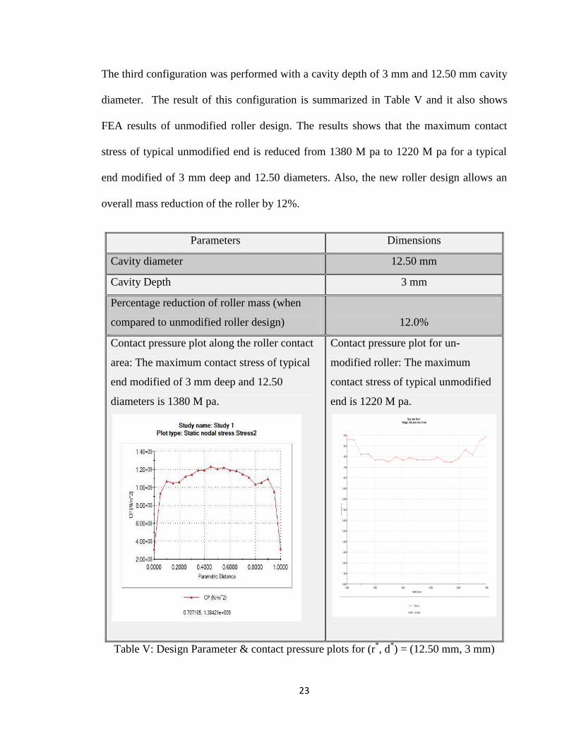
The third configuration was performed with a cavity depth of 3 mm and 12.50 mm cavity
diameter. The result of this configuration is summarized in Table V and it also shows
FEA results of unmodified roller design. The results shows that the maximum contact
stress of typical unmodified end is reduced from 1380 M pa to 1220 M pa for a typical
end modified of 3 mm deep and 12.50 diameters. Also, the new roller design allows an
overall mass reduction of the roller by 12%.
Parameters Dimensions
Cavity diameter 12.50 mm
Cavity Depth 3 mm
Percentage reduction of roller mass (when
compared to unmodified roller design)
12.0%
Contact pressure plot along the roller contact
area: The maximum contact stress of typical
end modified of 3 mm deep and 12.50
diameters is 1380 M pa.
Contact pressure plot for un-
modified roller: The maximum
contact stress of typical unmodified
end is 1220 M pa.
Table V: Design Parameter & contact pressure plots for (r*, d
*) = (12.50 mm, 3 mm)
24
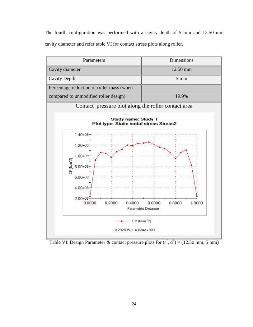
The fourth configuration was performed with a cavity depth of 5 mm and 12.50 mm
cavity diameter and refer table VI for contact stress plots along roller.
Parameters Dimensions
Cavity diameter 12.50 mm
Cavity Depth 5 mm
Percentage reduction of roller mass (when
compared to unmodified roller design)
19.9%
Contact pressure plot along the roller contact area
Table VI: Design Parameter & contact pressure plots for (r*, d
*) = (12.50 mm, 5 mm)
25
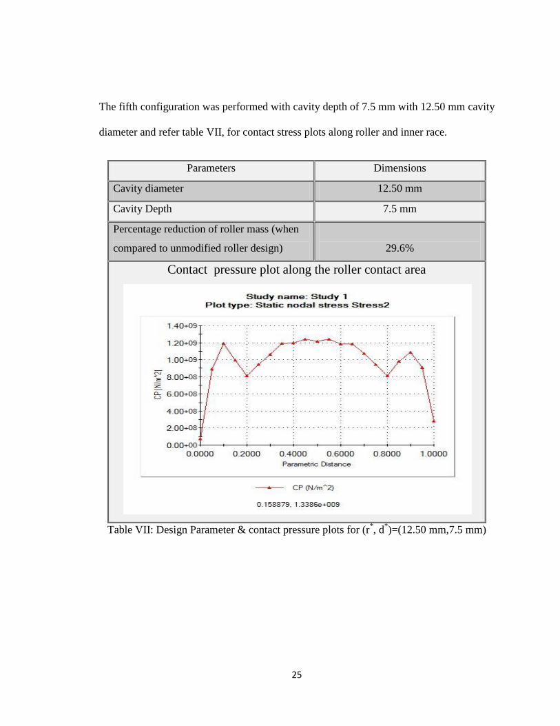
The fifth configuration was performed with cavity depth of 7.5 mm with 12.50 mm cavity
diameter and refer table VII, for contact stress plots along roller and inner race.
Parameters Dimensions
Cavity diameter 12.50 mm
Cavity Depth 7.5 mm
Percentage reduction of roller mass (when
compared to unmodified roller design)
29.6%
Contact pressure plot along the roller contact area
Table VII: Design Parameter & contact pressure plots for (r*, d
*)=(12.50 mm,7.5 mm)
26
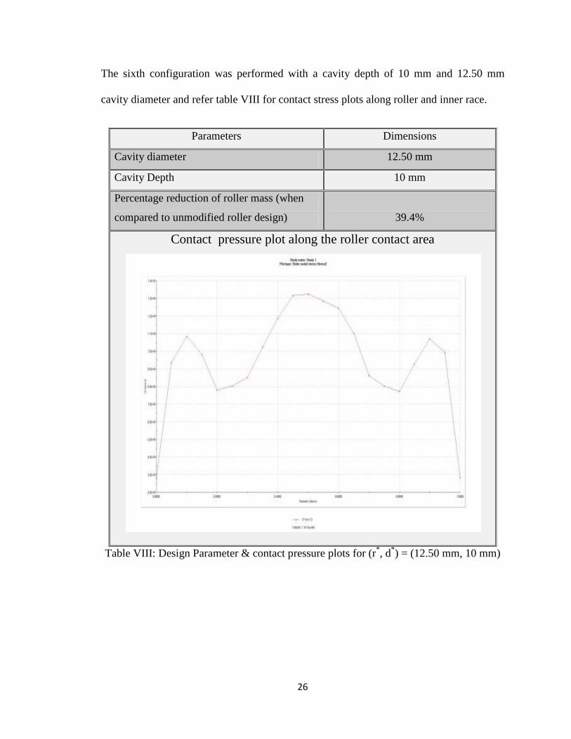
The sixth configuration was performed with a cavity depth of 10 mm and 12.50 mm
cavity diameter and refer table VIII for contact stress plots along roller and inner race.
Parameters Dimensions
Cavity diameter 12.50 mm
Cavity Depth 10 mm
Percentage reduction of roller mass (when
compared to unmodified roller design)
39.4%
Contact pressure plot along the roller contact area
Table VIII: Design Parameter & contact pressure plots for (r*, d
*) = (12.50 mm, 10 mm)
27
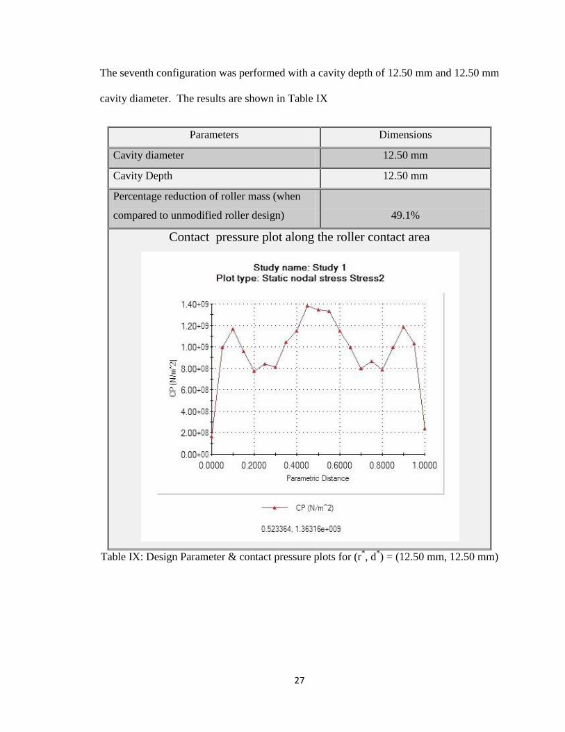
The seventh configuration was performed with a cavity depth of 12.50 mm and 12.50 mm
cavity diameter. The results are shown in Table IX
Parameters Dimensions
Cavity diameter 12.50 mm
Cavity Depth 12.50 mm
Percentage reduction of roller mass (when
compared to unmodified roller design)
49.1%
Contact pressure plot along the roller contact area
Table IX: Design Parameter & contact pressure plots for (r*, d
*) = (12.50 mm, 12.50 mm)
28
4.2 Summary and conclusion:
The double-ended hollow roller presented in this thesis is mainly focused on studying a
roller design which can develop uniform contact-stress distributions by eliminating any
edge stress and also recommend a roller bearing design which is easier to fabricate.
As shown in Table V-configuration 3, the maximum contact stress of typical unmodified
end is reduced from 1380 M pa to 1220 M pa by modifying the roller design with a cavity
depth of 3 mm and cavity diameter of 12.50 mm. Also this work presents a roller design
which has a lower manufacturing difficulty to fabricate when compared to conventional
roller with crowned ends. This alternative roller design also reduces the over-all mass of
the bearing assembly which in turn improves bearing life and its overall performance.
As illustrated in the above FEA configurations, with variations in the cavity depth d* ,
the roller is relaxed to deflect due to the hollow cavity at the ends of the roller when
subject to a compressive contact load, which in turn results in the reduction in contact
stress distribution at both ends of the roller.
29
REFERENCES
1. G.Lundberg, A. Palmgren, “Dynamic capacity of the rolling bearings”, Acta
Polytechnica Mechanical Engineering series, Vol.1 No.1,Royal Swedish
Academy of Engineering Sciences, Stockholm, Sweden,1947.
2. Hertz, H., “Miscellaneous papers- on the contact of elastic solids”, translation by
Jones,D.E , Macmillan and Co, Ltd., London,1898.
3. Harris, T.A, “The effect of misalignment on the fatigue life of cylindrical roller
bearing having crowned roller members”, ASME Journal of Lubrication
Technology, Vol.91,Apr 1969,pp 294-300.
4. Liu,J.Y., “The effect of misalignment on the life of high-speed cylindrical roller
bearings” ASME Journal of Lubrication Technology, Vol.93, NO.1,Jan 1971,pp
60-68.
5. H.Reusner, “The logarithmic roller profile-The key to superior performance of
cylindrical and taper bearing”, Ball Bearing Journal, 230(1987) 2-10.
6. S.H,Ju, T.L Horng,K.C Cha, “Comparison of contact pressures of crowned rollers
”in proceedings of the institution of mechanical engineering Part 1,Journal of
Eng. Tribology ,214 ,2000,pp147-156
7. SolidWorks® Simulation
® software
8. K.L Johnson, “Contact Mechanics”, Cambridge, London 1985.

30
9. Anthony C. Fischer-Cripps, “Introduction to contact mechanics”
31
APPENDIX-A
This section is gives complete over-view of geometrical, parametric setting utilized for
this research work and describes all the assumptions that are consider while performing
the research work and design parameters that used.
Lastly, this section also gives complete details of different analysis modules
characteristics used in this research work
Load and Restraints properties
Meshing control techniques
Contact set‟s selections and properties
32
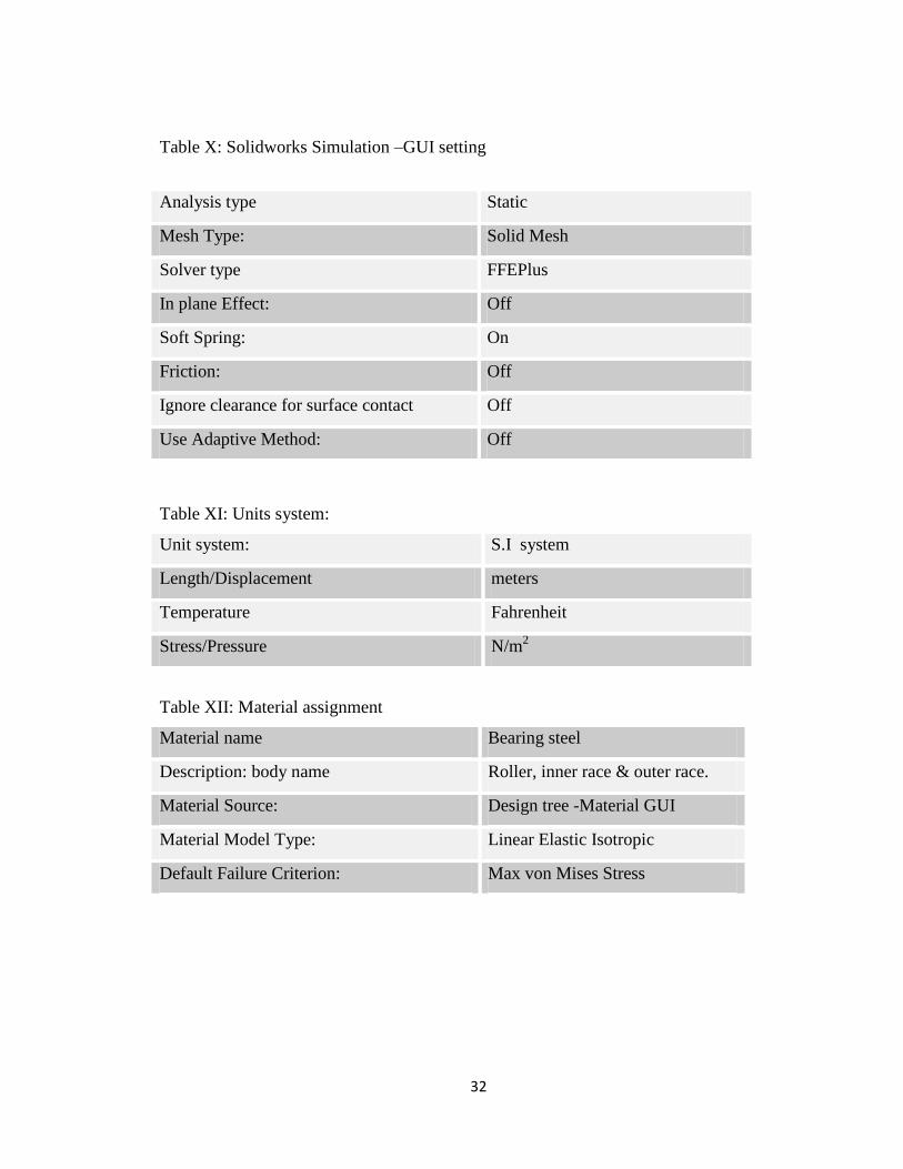
Table X: Solidworks Simulation –GUI setting
Table XI: Units system:
Unit system: S.I system
Length/Displacement meters
Temperature Fahrenheit
Stress/Pressure N/m2
Table XII: Material assignment
Material name Bearing steel
Description: body name Roller, inner race & outer race.
Material Source: Design tree -Material GUI
Material Model Type: Linear Elastic Isotropic
Default Failure Criterion: Max von Mises Stress
Analysis type Static
Mesh Type: Solid Mesh
Solver type FFEPlus
In plane Effect: Off
Soft Spring: On
Friction: Off
Ignore clearance for surface contact Off
Use Adaptive Method: Off
33
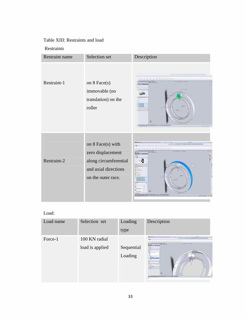
Table XIII: Restraints and load
Restraints
Restraint name Selection set Description
Restraint-1
on 8 Face(s)
immovable (no
translation) on the
roller
Restraint-2
on 8 Face(s) with
zero displacement
along circumferential
and axial directions
on the outer race.
Load:
Load name Selection set Loading
type
Description
Force-1 100 KN radial
load is applied
Sequential
Loading
34
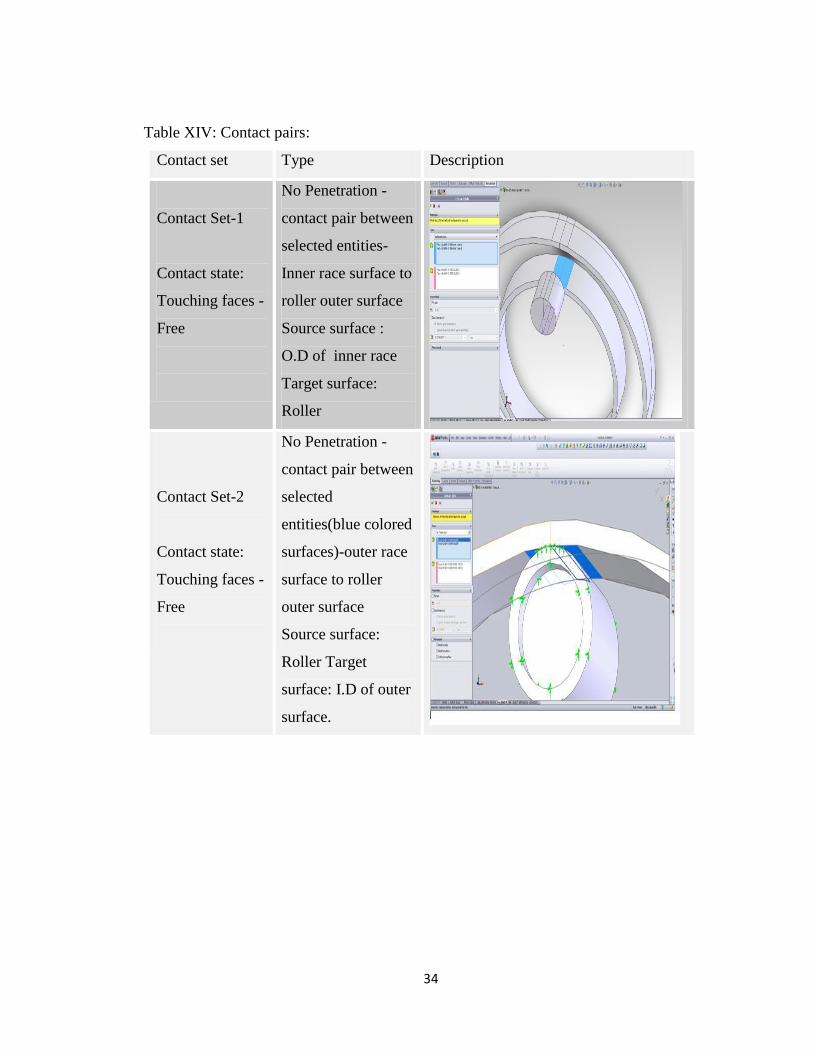
Table XIV: Contact pairs:
Contact set Type Description
Contact Set-1
Contact state:
Touching faces -
Free
No Penetration -
contact pair between
selected entities-
Inner race surface to
roller outer surface
Source surface :
O.D of inner race
Target surface:
Roller
Contact Set-2
Contact state:
Touching faces -
Free
No Penetration -
contact pair between
selected
entities(blue colored
surfaces)-outer race
surface to roller
outer surface
Source surface:
Roller Target
surface: I.D of outer
surface.
35
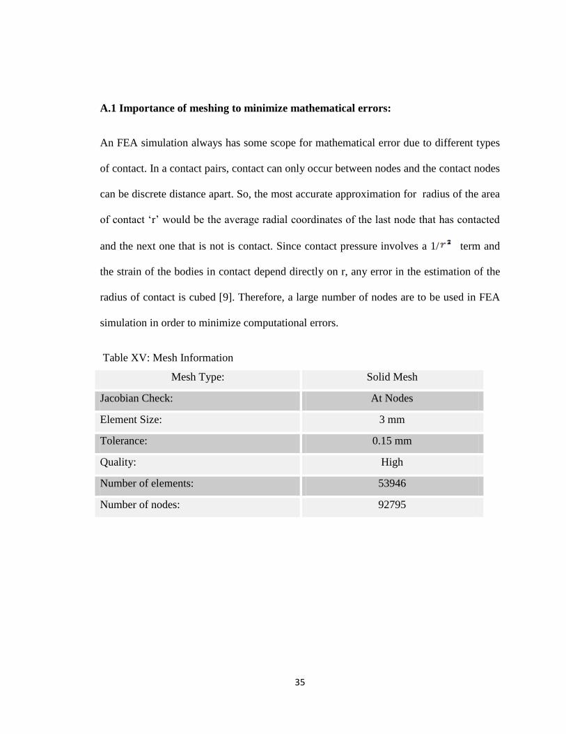
A.1 Importance of meshing to minimize mathematical errors:
An FEA simulation always has some scope for mathematical error due to different types
of contact. In a contact pairs, contact can only occur between nodes and the contact nodes
can be discrete distance apart. So, the most accurate approximation for radius of the area
of contact „r‟ would be the average radial coordinates of the last node that has contacted
and the next one that is not is contact. Since contact pressure involves a 1/ term and
the strain of the bodies in contact depend directly on r, any error in the estimation of the
radius of contact is cubed [9]. Therefore, a large number of nodes are to be used in FEA
simulation in order to minimize computational errors.
Table XV: Mesh Information
Mesh Type: Solid Mesh
Jacobian Check: At Nodes
Element Size: 3 mm
Tolerance: 0.15 mm
Quality: High
Number of elements: 53946
Number of nodes: 92795
36
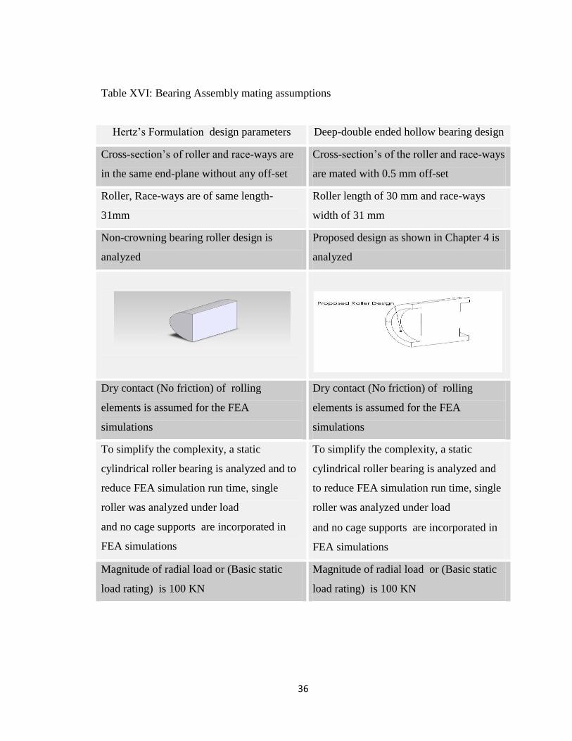
Table XVI: Bearing Assembly mating assumptions
Hertz‟s Formulation design parameters Deep-double ended hollow bearing design
Cross-section‟s of roller and race-ways are
in the same end-plane without any off-set
Cross-section‟s of the roller and race-ways
are mated with 0.5 mm off-set
Roller, Race-ways are of same length-
31mm
Roller length of 30 mm and race-ways
width of 31 mm
Non-crowning bearing roller design is
analyzed
Proposed design as shown in Chapter 4 is
analyzed
Dry contact (No friction) of rolling
elements is assumed for the FEA
simulations
Dry contact (No friction) of rolling
elements is assumed for the FEA
simulations
To simplify the complexity, a static
cylindrical roller bearing is analyzed and to
reduce FEA simulation run time, single
roller was analyzed under load
and no cage supports are incorporated in
FEA simulations
To simplify the complexity, a static
cylindrical roller bearing is analyzed and
to reduce FEA simulation run time, single
roller was analyzed under load
and no cage supports are incorporated in
FEA simulations
Magnitude of radial load or (Basic static
load rating) is 100 KN
Magnitude of radial load or (Basic static
load rating) is 100 KN