FDR Station 3 lift fixture, laser screens and brackets T. Brown and L. Morris with analysis support...
32
FDR Station 3 lift fixture, laser screens and brackets T. Brown and L. Morris with analysis support from A. Brooks December 3, 2007
-
Upload
harry-wilcox -
Category
Documents
-
view
214 -
download
2
Transcript of FDR Station 3 lift fixture, laser screens and brackets T. Brown and L. Morris with analysis support...
FDR
Station 3 lift fixture, laser screens and brackets
T. Brown and L. Morris with analysis support from A. Brooks
December 3, 2007
1. Are the requirements well defined?
1. Does the design meet the requirements?
2. Do the drawings define the design adequately to be used as the sole basis for fabrication and acceptance of the support fixture?
3. Does the analysis adequately underpin the design and have they been checked?
4. Has safety been adequately addressed in the design of the support fixture?
5. Can the support fixture be fabricated and installed within the budget and schedule identified in the project baseline?
6. Have all relevant chits from previous design reviews been adequately addressed?
Charge

Scope
This review covers the Station 3 lift fixture, laser mounts and screens.
The support fixtures for the MC’s and VV have already been covered in an earlier FDR.
The local alignment fixtures used to provide added positional adjustments of the MCHP will be shown.

Requirements
• Provide a lift structure that will allow safe movement of the MCHP over the VV
• Provide stable mounting brackets for the laser
• Provide stable laser path tracing support frames
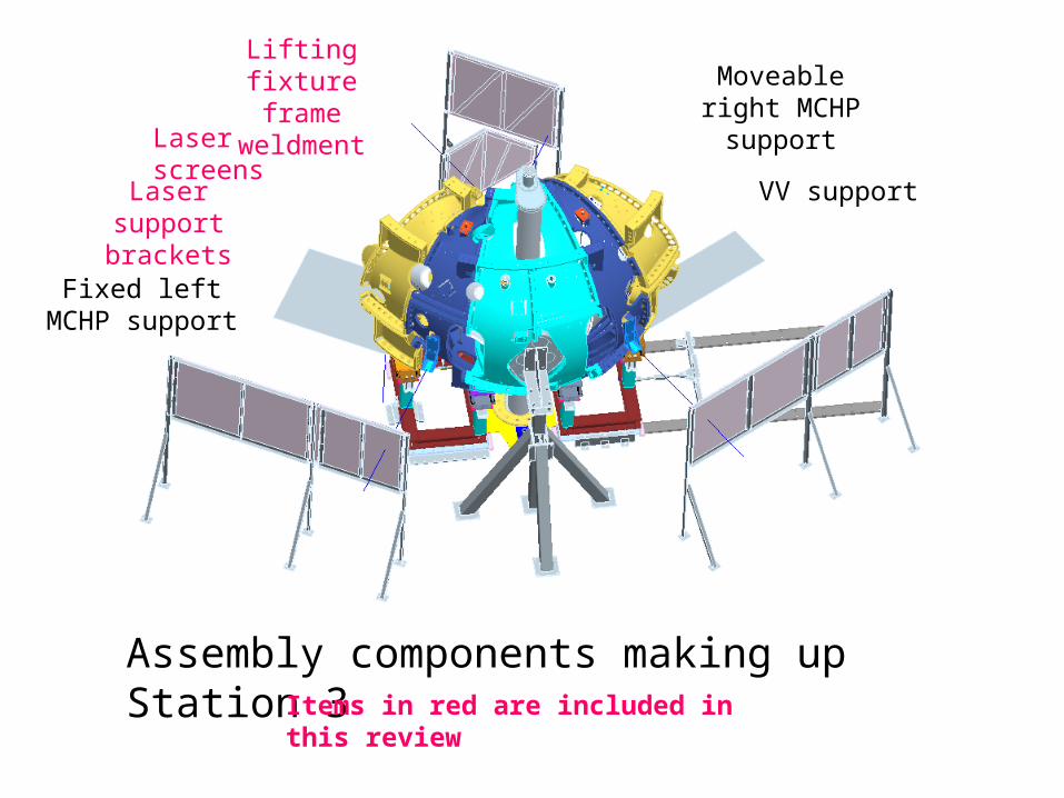
Assembly components making up Station 3
Laser screens
Laser support brackets
Fixed left MCHP support
Moveable right MCHP support
VV support
Lifting fixture frame weldment
Items in red are included in this review
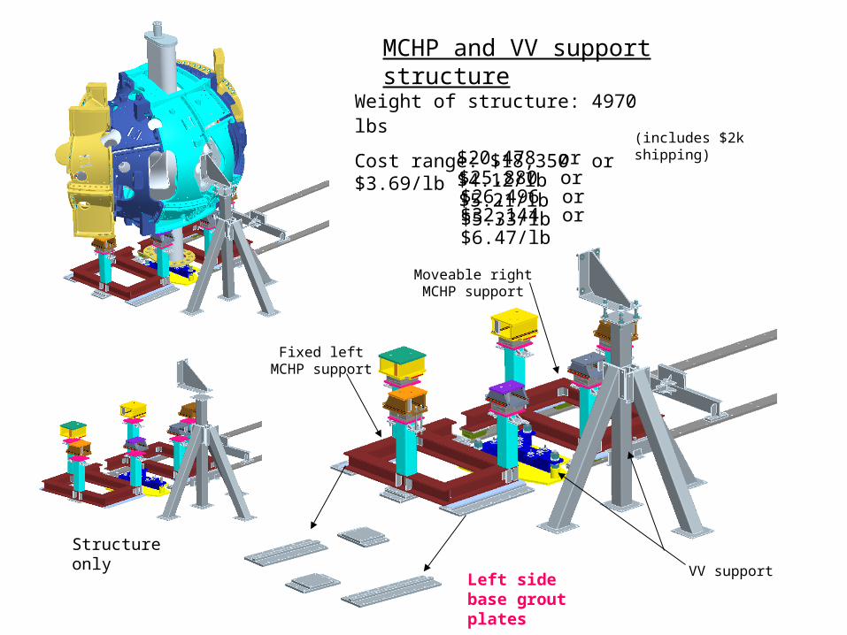
Structure only
Left side base grout plates
Fixed left MCHP support
Moveable right MCHP support
VV support
Weight of structure: 4970 lbs
Cost range: $18,350 or $3.69/lb
$25,880 or $5.21/lb$26,496 or $5.33/lb$32,144 or $6.47/lb
$20,478 or $4.12/lb(includes $2k shipping)
MCHP and VV support structure

Lifting fixture frame weldment
Lift fixture mounting bracket weldment
Sissco lift system
Lifting fixture frame weldment
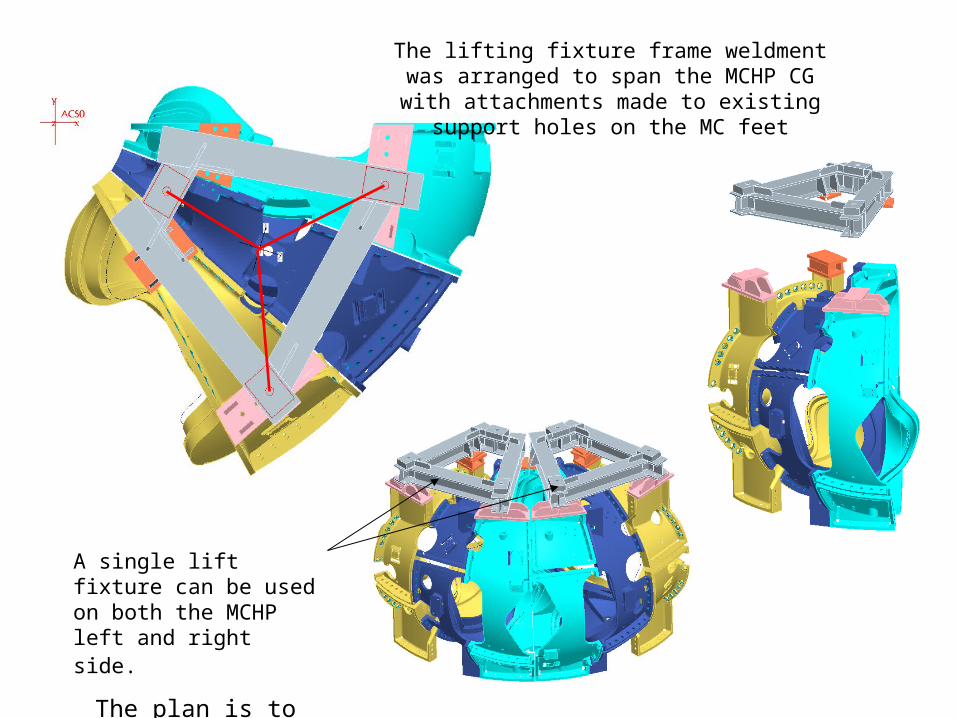
The lifting fixture frame weldment was arranged to span the MCHP CG with attachments made to
existing support holes on the MC feet
A single lift fixture can be used on both the MCHP left and right side.
The plan is to procure only one.

Lifting fixture frame weldment drawing se185-316
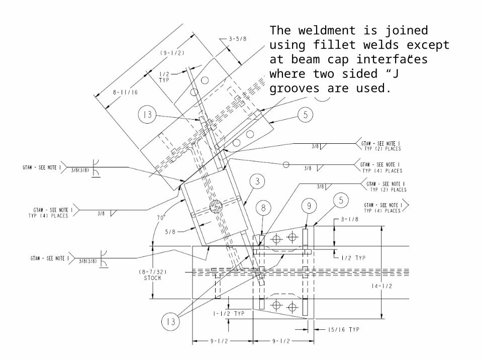
The weldment is joined using fillet welds except at beam cap interfaces where two sided “J” grooves are used.
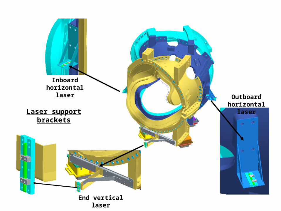
Laser support brackets
Inboard horizontal laser
Outboard horizontal laser
End vertical laser

Reworked Screen
Reworked Screen
New Screens
New left side base / grout
plates
New and reworked laser screens
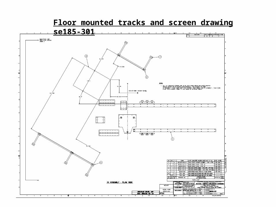
Floor mounted tracks and screen drawing se185-301

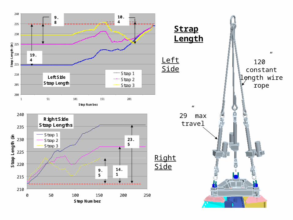
Left SideStrap Length
200
205
210
215
220
225
230
235
240
1 51 101 151 201
Step Number
Str
ap L
eng
th (
in)
Strap 1Strap 2Strap 3
19.4
9.8 10.4
Right SideStrap Lengths
210
215
220
225
230
235
240
0 50 100 150 200 250
Step Number
Str
ap
Len
gth
(in
) Strap 1Strap 2Strap 3
23.5
14.19.5
Left Side
Right Side
Strap Length
29” max travel
120” constant length wire
rope
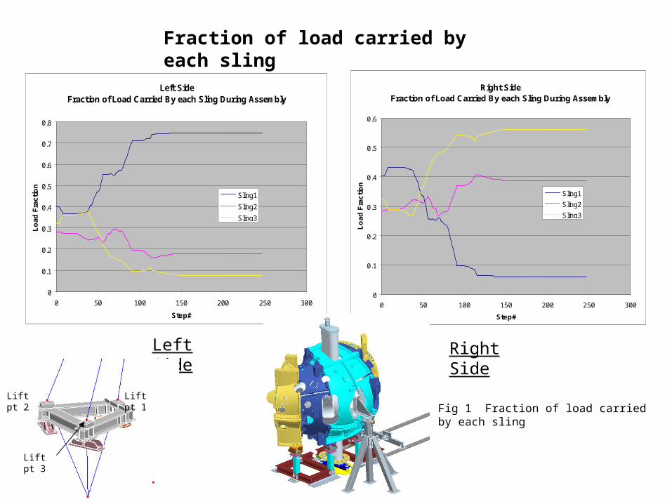
Right SideFraction of Load Carried By each Sling During Assembly
0
0.1
0.2
0.3
0.4
0.5
0.6
0 50 100 150 200 250 300
Step#
Lo
ad
Fra
cti
on
Sling1
Sling2
Sling3
Left SideFraction of Load Carried By each Sling During Assembly
0
0.1
0.2
0.3
0.4
0.5
0.6
0.7
0.8
0 50 100 150 200 250 300
Step#
Lo
ad F
ract
ion
Sling1
Sling2
Sling3
Left Side Right Side
Fraction of load carried by each sling
MCHP CG
Lift pt 3Lift pt 1Lift pt 2
Lift pt 3
Fig 1 Fraction of load carried by each sling
Lift pt 1Lift pt 2
Lift pt 3
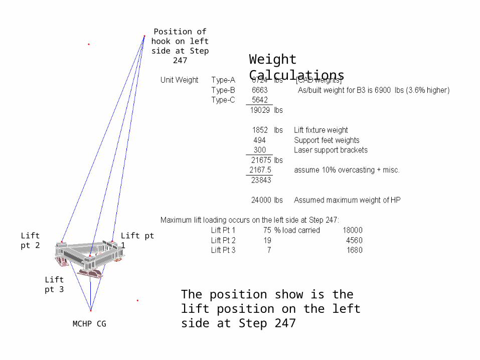
MCHP CG
Position of hook on left side at
Step 247
The position show is the lift position on the left side at Step 247
Weight Calculations
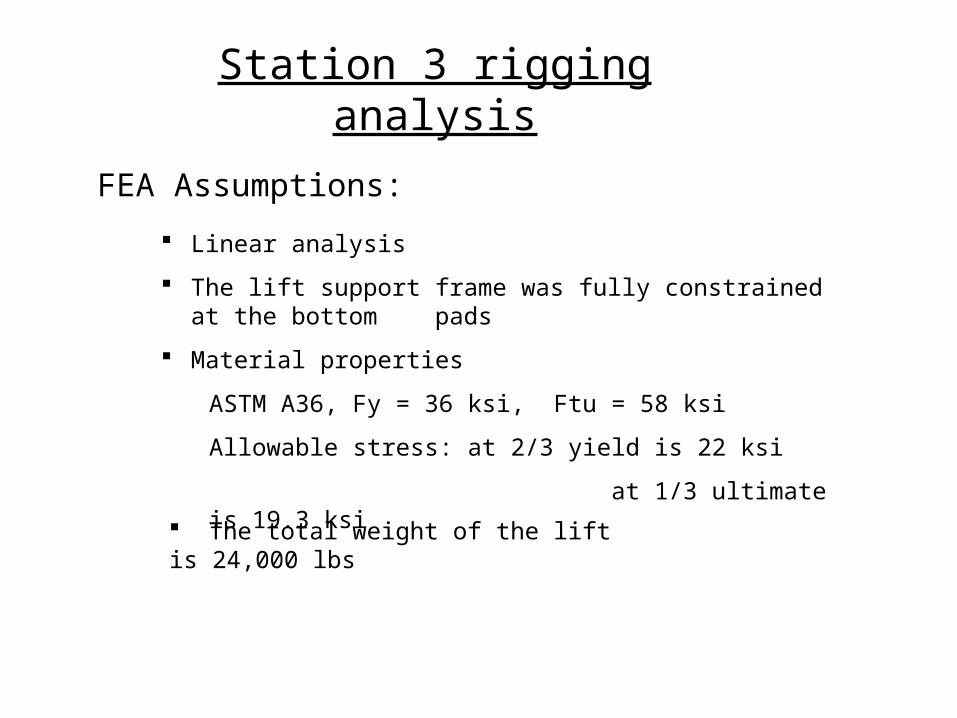
FEA Assumptions:
Linear analysis
The lift support frame was fully constrained at the bottom pads
Material properties
ASTM A36, Fy = 36 ksi, Ftu = 58 ksi
Allowable stress: at 2/3 yield is 22 ksi
at 1/3 ultimate is 19.3 ksi
The total weight of the lift is 24,000 lbs
Station 3 rigging analysis
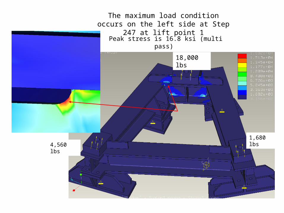
The maximum load condition occurs on the left side at Step 247 at lift point 1
Peak stress is 16.8 ksi (multi pass)
18,000 lbs
4,560 lbs1,680 lbs
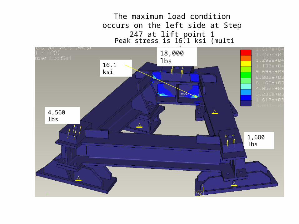
The maximum load condition occurs on the left side at Step 247 at lift point 1
Peak stress is 16.1 ksi (multi pass)
18,000 lbs
4,560 lbs
1,680 lbs
16.1 ksi
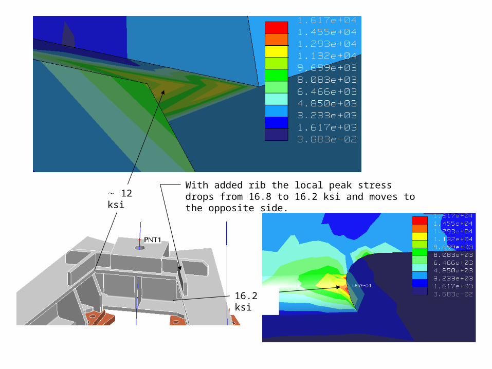
12 ksi
With added rib the local peak stress drops from 16.8 to 16.2 ksi and moves to the opposite side.
16.2 ksi
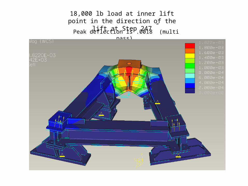
18,000 lb load at inner lift point in the direction of the lift at Step 247
Peak deflection is .0018” (multi pass)
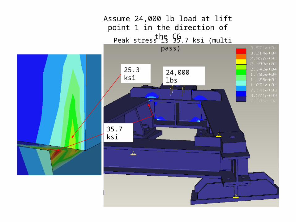
Assume 24,000 lb load at lift point 1 in the direction of the CG
Peak stress is 35.7 ksi (multi pass)
25.3 ksi
35.7 ksi
24,000 lbs
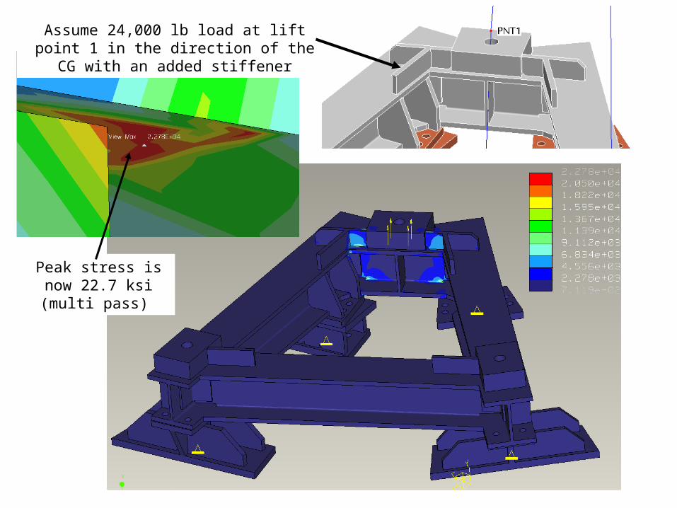
Assume 24,000 lb load at lift point 1 in the direction of the CG with an added stiffener
Peak stress is now 22.7 ksi (multi pass)
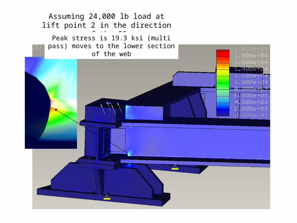
Assuming 24,000 lb load at lift point 2 in the direction of the CG
Peak stress is 19.3 ksi (multi pass) moves to the lower section of the web
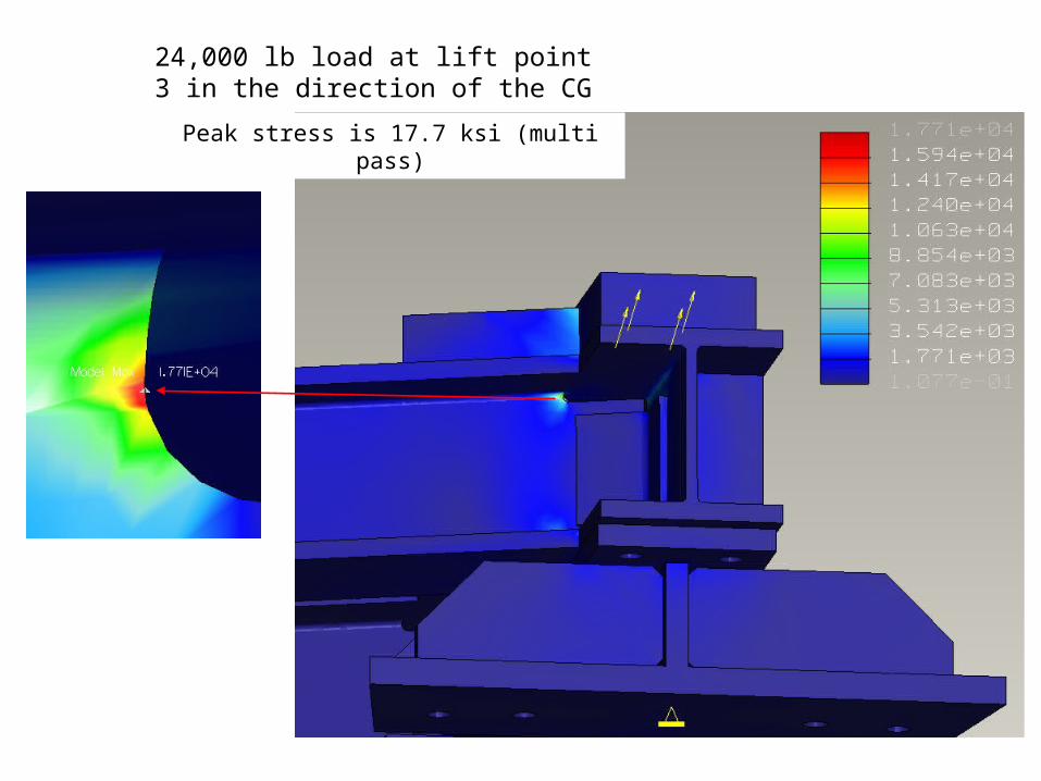
24,000 lb load at lift point 3 in the direction of the CG
Peak stress is 17.7 ksi (multi pass)

Fixture Reaction Loads
1-8 bolt, SAE J429 Grade B8 Bolt Ftu = 150 ksi Fy = 130 ksi
Tension allowable (based on 1/3 ult) = 27,551 lbs
Fixture Reaction Loads
1-8 bolt, SAE J429 Grade B8 Bolt Ftu = 150 ksi Fy = 130 ksi
Tension allowable (based on 1/3 ult) = 27,551 lbs

Lifting shackle link calculation

Station 2 style adjuster plates mounted to the support base
Local alignment fixtures are used for positional adjustments (similar to Station 2)
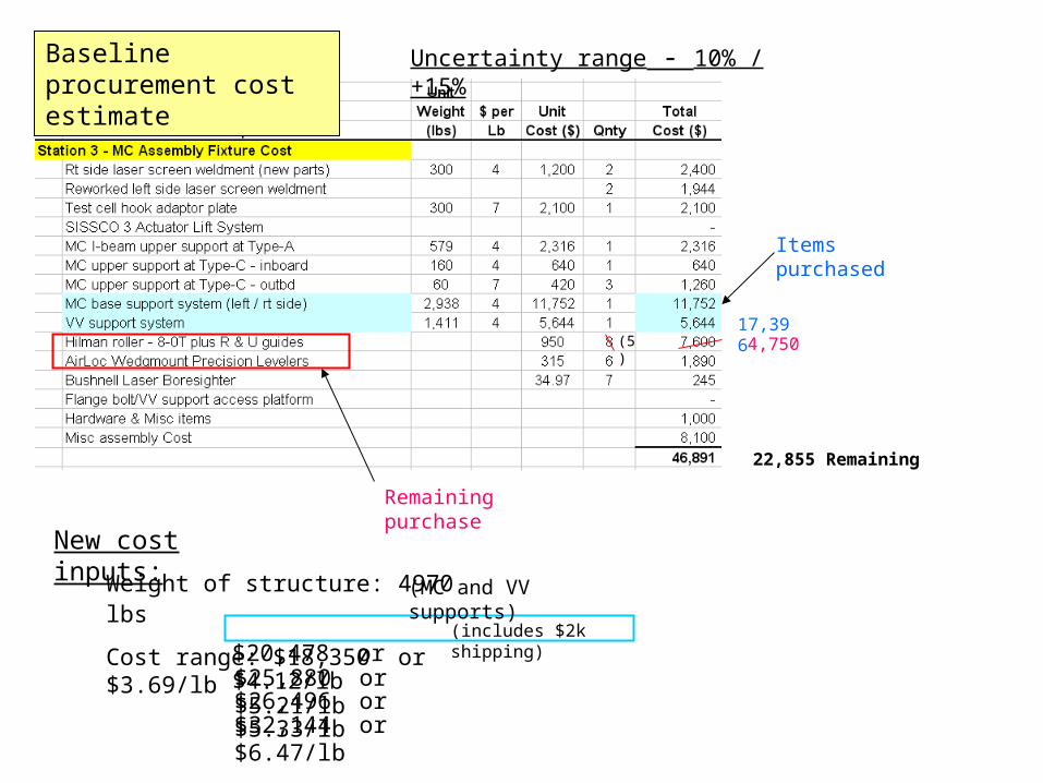
Baseline procurement cost estimate
Weight of structure: 4970 lbs
Cost range: $18,350 or $3.69/lb
$25,880 or $5.21/lb$26,496 or $5.33/lb$32,144 or $6.47/lb
$20,478 or $4.12/lb(includes $2k shipping)
(MC and VV supports)
(5)17,396
4,750
22,855 Remaining
Remaining purchase
New cost inputs:
Uncertainty range - 10% / +15%
Items purchased

Estimate for outstanding procurements
22,855 Left from original budget
$ 5,023 Over original budget
Note: if all procurements come in at the $3.69/lb cost of the first procurement then the hardware cost would come in $1948 under budget.
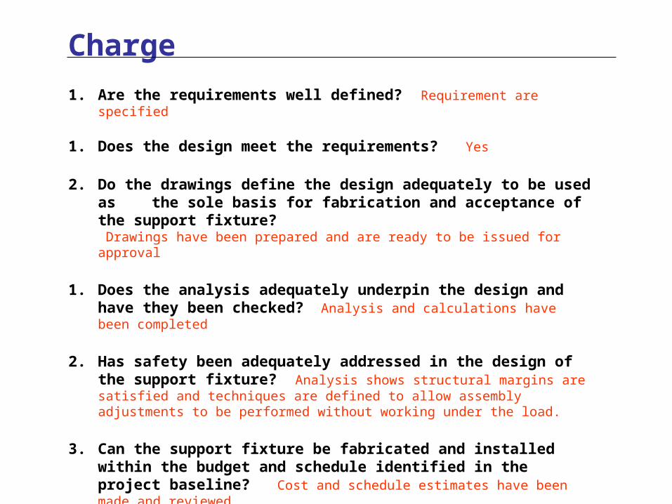
1. Are the requirements well defined? Requirement are specified
1. Does the design meet the requirements? Yes
2. Do the drawings define the design adequately to be used as the sole basis for fabrication and acceptance of the support fixture? Drawings have been prepared and are ready to be issued for approval
1. Does the analysis adequately underpin the design and have they been checked? Analysis and calculations have been completed
2. Has safety been adequately addressed in the design of the support fixture? Analysis shows structural margins are satisfied and techniques are defined to allow assembly adjustments to be performed without working under the load.
3. Can the support fixture be fabricated and installed within the budget and schedule identified in the project baseline? Cost and schedule estimates have been made and reviewed.
4. Have all relevant chits from previous design reviews been adequately addressed? This is new information; no chits are outstanding.
Charge