FDD-TDD Interference Analysis Involving WiMAX Systems Final 091103
39
Managing TDD-FDD Interfer ence between Co-Sited Base Stations deployed in Adjacent Frequency Blocks 3 rd November 2009 Copyright 2007 WiMAX Forum. All rights reserved. “WiMAX,” “Fixed WiMAX,” “Mobile WiMAX,” “WiMAX Forum,” the WiMAX Forum logo, "WiMAX Forum Certified,” and the WiMAX Forum Certified logo are trademarks of the WiMAX Forum. All other trademarks are the properties of their respective owners.
Transcript of FDD-TDD Interference Analysis Involving WiMAX Systems Final 091103

8/8/2019 FDD-TDD Interference Analysis Involving WiMAX Systems Final 091103
http://slidepdf.com/reader/full/fdd-tdd-interference-analysis-involving-wimax-systems-final-091103 1/39
Managing TDD-FDD Interference
between Co-Sited Base Stations
deployed in Adjacent Frequency
Blocks
3rd November 2009
Copyright 2007 WiMAX Forum. All rights reserved. “WiMAX,” “Fixed WiMAX,” “Mobile WiMAX,” “WiMAX
Forum,” the WiMAX Forum logo, "WiMAX Forum Certified,” and the WiMAX Forum Certified logo are
trademarks of the WiMAX Forum. All other trademarks are the properties of their respective owners.
8/8/2019 FDD-TDD Interference Analysis Involving WiMAX Systems Final 091103
http://slidepdf.com/reader/full/fdd-tdd-interference-analysis-involving-wimax-systems-final-091103 2/39
WiMAX FORUM
WiMAX FORUM 2 WHITE PAPER
www.wimaxforum.org • [email protected]
8/8/2019 FDD-TDD Interference Analysis Involving WiMAX Systems Final 091103
http://slidepdf.com/reader/full/fdd-tdd-interference-analysis-involving-wimax-systems-final-091103 3/39
WiMAX FORUM
Executive Summary
The frequency assignments for broadband wireless applications within the
2500MHz~2690MHz range are being prepared for auction in many countries around the
world. Regulators1
and potential service providers are interested in minimizing inter-
network interference challenges and one critical issue is the possibility for interference
between TDD systems and FDD systems operating in adjacent spectrum blocks in the
same geographical area. This paper provides guidance to supplement the regulations to
assist potential service providers for the frequency usage of FDD/TDD applications in a
common co-siting deployment scenario.
Adjacent TDD systems can be synchronized to reduce the impact of inter-network
interference and this is reported in detail in a companion WiMAX Forum® white paper 2.
However this is not the case for mixed systems in adjacent spectrum blocks.
The interference cases between a TDD system and a FDD system consist of 4 scenarios
according to the signal path between two systems summarised below;
1) Scenario 1: DL→DL: BS of the adjacent system interferes with MS of the target system
2) Scenario 2:
UL→DL: MS of the adjacent system interferes with MS of the target system
3) Scenario 3:
DL→UL: BS of the adjacent system interferes with BS of the target system
4) Scenario 4:
1For Example European Commission Decision 2008/477 contains a specific annex
detailing the technical regulatory conditions for minimizing inter network interference.2
WiMAX Forum® White paper: “TDD-TDD Interference Analysis involving
Synchronized WiMAX systems” – 18 September 2009.
http://www.wimaxforum.org/sites/wimaxforum.org/files/WiMAX_TDD-
TDD_%20Interference_analysis_090918_0.pdf
WiMAX FORUM 3 WHITE PAPER
www.wimaxforum.org • [email protected]

8/8/2019 FDD-TDD Interference Analysis Involving WiMAX Systems Final 091103
http://slidepdf.com/reader/full/fdd-tdd-interference-analysis-involving-wimax-systems-final-091103 4/39
WiMAX FORUM
UL→UL: MS of the adjacent system interferes with BS of the target system
Many studies already conclude that scenario 3 presents the worst case, having the
possibility to impact an entire cell or sector with no temporal mitigation. In this paper,this scenario 3 (the interference between BS’s of two systems) is analyzed, and then the
interference isolation to secure a certain performance of the system is derived.
Finally, the results of an antenna measurement campaign are provided which can add
useful additional inter-system isolation allowing closer coexistence between systems in
adjacent blocks. In particular the site sharing case is considered.
The studies conclude that through application of the European regulatory block edge
mask, the baseline out of block emission levels and readily achievable additional antenna
isolation, systems in adjacent frequency blocks can successfully site share (co-located
base stations) with a minimal capacity loss due to adjacent channel interference.
This work builds upon previous analysis carried out on behalf of the WiMAX Forum® by
the independent analysts Roke Manor Research titled “Practical Compatibility and
Coexistence Measures Analysis”3
which summarized a number of studies carried out
within the ITU-R and other bodies from a WiMAX technology perspective.
3Downloadable from:
http://www.wimaxforum.org/resources/documents/marketing/whitepapers
WiMAX FORUM 4 WHITE PAPER
www.wimaxforum.org • [email protected]

8/8/2019 FDD-TDD Interference Analysis Involving WiMAX Systems Final 091103
http://slidepdf.com/reader/full/fdd-tdd-interference-analysis-involving-wimax-systems-final-091103 5/39
WiMAX FORUM
Contents
Executive Summary ....................................................................................... 3
Contents......................................................................................................... 5
Tables ............................................................................................................ 6
Figures ........................................................................................................... 7
List of Abbreviations......................................................................................8
References.....................................................................................................9
1. Introduction .........................................................................................10
2. Coexistence considerations between TDD and FDD systems............. 12
2.1. Interference scenarios between TDD and FDD systems................ 12
2.2. Factors Affecting Interference......................................................... 14
2.3. Methods of mitigating interference for co-existence..................... 16
3. Simulation ............................................................................................ 18
3.1. Simulation methodology.................................................................... 18
3.2. Simulation Results & Analysis.......................................................... 24
3.2.1. Capacity Degradation and ACI................................................. 25
3.2.2. Deriving the Additional Isolation ............................................. 26
3.2.3. Analysis..................................................................................... 27
4. Antenna isolation mitigation ................................................................28
4.1. Horizontal Separation Results .......................................................... 28
4.2. Vertical Separation Results .............................................................. 30
4.3. Horizontal and vertical separation ................................................... 32
4.4. Result summary................................................................................. 32
4.5. Result analysis .................................................................................. 33
5. Conclusion ...........................................................................................35
ANNEX A. Block Edge Mask identified in EC Decision (2008/477/EC)....... 36
WiMAX FORUM 5 WHITE PAPER
www.wimaxforum.org • [email protected]
8/8/2019 FDD-TDD Interference Analysis Involving WiMAX Systems Final 091103
http://slidepdf.com/reader/full/fdd-tdd-interference-analysis-involving-wimax-systems-final-091103 6/39
WiMAX FORUM
Tables
Table 1. Interference scenarios.......................................................................................... 13
Table 2. RF characteristics & Antenna pattern ................................................................. 18
Table 3. Simulation Parameters ........................................................................................ 19
Table 4. Parameters for COST231 HATA model.............................................................. 20
Table 5. Uplink capacity loss & Acceptable ACI level..................................................... 26
Table 6. OOBE & Additional isolation ............................................................................. 27
Table 7. Installation for Measurement .............................................................................. 28
Table 8. Summary of antenna configuration..................................................................... 33
Table A-1. Block specific requirement for BS out-of-block in unrestricted band
(Symmetric) .............................................................................................................. 37
Table A-2. Block specific requirement for BS out-of-block in restricted band (Symmetric)
................................................................................................................................... 38
Table A-3. ACLR calculation of unrestricted block.......................................................... 38
Table A-4. ACLR calculation of restricted block.............................................................. 38
WiMAX FORUM 6 WHITE PAPER
www.wimaxforum.org • [email protected]

8/8/2019 FDD-TDD Interference Analysis Involving WiMAX Systems Final 091103
http://slidepdf.com/reader/full/fdd-tdd-interference-analysis-involving-wimax-systems-final-091103 7/39
WiMAX FORUM
Figures
Figure 1. Frequency allocation for 2500-2690MHz ......................................................... 10
Figure 2. Interference paths between TDD and FDD systems ......................................... 12
Figure 3. FRP1 and FRP3 ................................................................................................. 16
Figure 4. Antenna separation ............................................................................................ 17
Figure 5. Horizontal(70º) & Vertical(7º) antenna pattern ................................................. 21
Figure 6. Wrap around cell type........................................................................................ 22
Figure 7. Uplink SLS procedure ....................................................................................... 24
Figure 8. Uplink capacity degradation ratio vs. Irx/Nt....................................................... 25
Figure 9. Antenna isolation vs. horizontal spacing ........................................................... 29
Figure 10. Boresight angle vs. antenna isolation .............................................................. 29
Figure 11. Electrical Down-tilt vs. antenna isolation........................................................ 30
Figure 12. Vertical isolation vs. antenna isolation ............................................................ 30
Figure 13. vertical angle vs. antenna isolation.................................................................. 31
Figure 14. Electrical Down-tilt vs. antenna isolation ....................................................... 31
Figure 15. Horizontal & vertical spacing vs. antenna isolation........................................ 32
Figure A-1. Baseline requirement of block edge mask..................................................... 36Figure A-2. Unrestricted block edge mask for BS............................................................ 37
WiMAX FORUM 7 WHITE PAPER
www.wimaxforum.org • [email protected]

8/8/2019 FDD-TDD Interference Analysis Involving WiMAX Systems Final 091103
http://slidepdf.com/reader/full/fdd-tdd-interference-analysis-involving-wimax-systems-final-091103 8/39
WiMAX FORUM
List of Abbreviations
ACLR Adjacent Channel Leakage Ratio
ACS Adjacent Channel Sensitivity
ACIR Adjacent Channel Interference Ratio
AMC Adaptive Modulation and Coding
BEM Block Edge Mask
BER Bit Error Rate
BS Base Station
DL Downlink
EIRP Effective Isotropic Radiated Power
ETSI European Telecommunications Standards Institute
FDD Frequency Division Duplex
FFT Fast Fourier Transform
FRP Frequency Reuse Pattern
ITU International Telecommunication UnionMCS Modulation and Coding Scheme
MS Mobile Station
NF Noise Figure
NLOS Non-Line Of Sight
OOBE Out Of Band Emission
PUSC Partial Used Sub-Carrier
TDD Time Division Duplex
UL Uplink
WiMAX FORUM 8 WHITE PAPER
www.wimaxforum.org • [email protected]

8/8/2019 FDD-TDD Interference Analysis Involving WiMAX Systems Final 091103
http://slidepdf.com/reader/full/fdd-tdd-interference-analysis-involving-wimax-systems-final-091103 9/39
WiMAX FORUM
References
[1] 3GPP, “Universal Mobile Telecommunications System (UMTS); Radio Frequency
(RF) System Scenarios (3GPP TR 25.942 version 6.4.0 Release 6)”, 3GPP TR 25.942,
March 2005
[2] “EC Decision on the harmonization of the 2500-2690MHz frequency band for
terrestrial systems capable of providing electronic communications services in the
Community”, 2008/477/EC June 24th, 2008
[3] WiMAX Forum®, WiMAX System Evaluation Methodology Version 2.1, July 7,
2008
[4] “Practical Compatibility and Coexistence Measures Analysis”; Roke Manor Research;
August 2008. WiMAX Forum sponsored research.
WiMAX FORUM 9 WHITE PAPER
www.wimaxforum.org • [email protected]
8/8/2019 FDD-TDD Interference Analysis Involving WiMAX Systems Final 091103
http://slidepdf.com/reader/full/fdd-tdd-interference-analysis-involving-wimax-systems-final-091103 10/39
WiMAX FORUM
1. Introduction
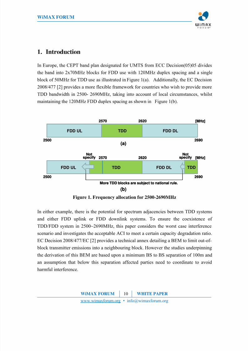
In Europe, the CEPT band plan designated for UMTS from ECC Decision(05)05 divides
the band into 2x70MHz blocks for FDD use with 120MHz duplex spacing and a single
block of 50MHz for TDD use as illustrated in Figure 1(a). Additionally, the EC Decision
2008/477 [2] provides a more flexible framework for countries who wish to provide more
TDD bandwidth in 2500- 2690MHz, taking into account of local circumstances, whilst
maintaining the 120MHz FDD duplex spacing as shown in Figure 1(b).
FDD UL TDD FDD DL
2570 2620 [MHz]
2500 2690
FDD UL TDD FDD DL
2570 2620 [MHz]
TDD
Notspecify
Notspecify
2500 2690
More TDD blocks are subject to national rule.
(a)
(b)
FDD UL TDD FDD DL
2570 2620 [MHz]
2500 2690
FDD UL TDD FDD DL
2570 2620 [MHz]
TDD
Notspecify
Notspecify
2500 2690
More TDD blocks are subject to national rule.
(a)
(b)
Figure 1. Frequency allocation for 2500-2690MHz
In either example, there is the potential for spectrum adjacencies between TDD systems
and either FDD uplink or FDD downlink systems. To ensure the coexistence of
TDD/FDD system in 2500~2690MHz, this paper considers the worst case interference
scenario and investigates the acceptable ACI to meet a certain capacity degradation ratio.
EC Decision 2008/477/EC [2] provides a technical annex detailing a BEM to limit out-of-
block transmitter emissions into a neighbouring block. However the studies underpinning
the derivation of this BEM are based upon a minimum BS to BS separation of 100m and
an assumption that below this separation affected parties need to coordinate to avoid
harmful interference.
WiMAX FORUM 10 WHITE PAPER
www.wimaxforum.org • [email protected]

8/8/2019 FDD-TDD Interference Analysis Involving WiMAX Systems Final 091103
http://slidepdf.com/reader/full/fdd-tdd-interference-analysis-involving-wimax-systems-final-091103 11/39
WiMAX FORUM
In areas of dense deployment, suitable base station sites maybe limited, forcing
competing service providers to share sites and co-locate. This can be attractive (or
mandated) from the environmental aspect too.
This paper provides a method to mitigate interference in this situation based upon the
derived acceptable ACI to build upon the technical licensing measures detailed in EC
Decision 2008/477/EC [2].
WiMAX FORUM 11 WHITE PAPER
www.wimaxforum.org • [email protected]

8/8/2019 FDD-TDD Interference Analysis Involving WiMAX Systems Final 091103
http://slidepdf.com/reader/full/fdd-tdd-interference-analysis-involving-wimax-systems-final-091103 12/39
WiMAX FORUM
2. Coexistence considerations between TDD and FDD systems
2.1. Interference scenarios between TDD and FDD systems
FDD and TDD indicate the duplex division method type for uplink and downlink. FDD is
the duplex method to assign separate frequency bands for uplink transmission and for
downlink transmission, thus FDD requires the paired band. A frequency separation
between uplink and downlink transmissions is required due to the characteristic of FDD
and known as ‘Duplex spacing’. Generally, FDD downlink band is assigned as the upper
band of the pair. TDD is the duplex method to assign alternate time slots for uplink anddownlink transmission on the same frequency in an assigned band. This chapter defines
the interference scenario for coexistence between FDD and TDD systems. When TDD
and FDD systems are situated in the adjacent channel and in close proximity, four key
interference scenarios can be identified.
Figure 2. Interference paths between TDD and FDD systems
Figure 2 shows the band allocation and interference paths between TDD and FDD
systems. Both edge channels of the TDD band can receive and create interference from
the adjacent edge channel of the FDD uplink and downlink. In Figure 2, the red arrows
WiMAX FORUM 12 WHITE PAPER
www.wimaxforum.org • [email protected]

8/8/2019 FDD-TDD Interference Analysis Involving WiMAX Systems Final 091103
http://slidepdf.com/reader/full/fdd-tdd-interference-analysis-involving-wimax-systems-final-091103 13/39
WiMAX FORUM
indicate the interference signal and the blue arrows indicate the desired signal.
The four key interference scenarios between the TDD and FDD systems are identified in
Table 1.
Table 1. Interference scenariosIndex Interference Path Scenario
1BS to MS
( DL DL)
BS of interferer system in adjacent channel to
MS of victim system
2MS to MS
( UL DL)
MS of interferer system in adjacent channel to
MS of victim system
3BS to BS
( DL UL)
BS of interferer system in adjacent channel to
BS of victim system
4MS to BS
( UL UL)
MS of interferer system in adjacent channel to
BS of victim system
The interference potential in each of the above scenarios depends upon the characteristics
of BS and MS. In the first scenario, the effect of interference between interferer system
and victim system is related with their respective locations. For example, if the BS of
interferer system is located at cell edge of victim system, the MS at the cell edge can
suffer significant interference from the BS of the interferer system. In the second scenario,
when the MS in downlink is very close to the MS of interferer system in uplink, the MS
of interferer system in uplink interferes with the MS of victim system. Because the
transmitter power of the MS is smaller than that of the BS and the relative mobility of the
MS can contribute to a transient nature to the interference, other studies have concluded
that this interference level is negligible when considered across a network 4
. The worst
case in these two scenarios occurs with a low probability.
On the other hand, the third and the fourth scenarios are more serious, because the BS or
MS interferes with the fixed BS of the victim system with a relatively constant level. In
this regard, the third scenario is the most severe. The reason is that BS’s are generally
located in high positions for coverage, leading to a high probability that the propagation
loss between BS of victim system and BS of interferer system is low.
Therefore, scenario 3 as the worst case of four interference scenarios is analyzed in this
paper.
4ITU-R Report M.2113 or ECC Report 119
WiMAX FORUM 13 WHITE PAPER
www.wimaxforum.org • [email protected]
8/8/2019 FDD-TDD Interference Analysis Involving WiMAX Systems Final 091103
http://slidepdf.com/reader/full/fdd-tdd-interference-analysis-involving-wimax-systems-final-091103 14/39
WiMAX FORUM
However, considering that a fixed MS of the interferer system uses an outdoor directional
antenna, the location of the MS may be a critical factor in scenario 4 like the case of BS
to BS.
2.2. Factors Affecting Interference
Out of Block Emission
Out of block emission (OOBE) is the emission on a frequency or frequencies
immediately outside the necessary bandwidth which results from the modulation process,
but excluding spurious emission.
Receiver selectivity
Receiver selectivity indicates the ability of receiver to not reject unwanted signals in
adjacent channels. Ideally, the receiver filter passes just the signal in band but practical
implementations preclude this. Receiver selectivity indicates the degree of attenuation of
the signal in the adjacent channel. The scale of the receiver selectivity is represented as
ACS which is the ratio of the attenuation of the receiver filter co-channel to the
attenuation of the receiver filter in the adjacent channel.
Transmitter Adjacent Channel Emissions
Imperfections in system implementation lead to low level unwanted transmitter emissions
that fall outside the desired channel. These emissions can appear to a receiver in the
adjacent channels as an in-band signal and create interference that can affect the ability of
the receiver to de-modulate the wanted signal. ACLR is the ratio of the transmitter
wanted channel power level to the adjacent channel unwanted power level based on a
common evaluation bandwidth.
Adjacent channel interference ratio
The resultant interference impact to the adjacent channel due to the combination of
ACLR and ACS is represented by ACIR, and is given by
WiMAX FORUM 14 WHITE PAPER
www.wimaxforum.org • [email protected]

8/8/2019 FDD-TDD Interference Analysis Involving WiMAX Systems Final 091103
http://slidepdf.com/reader/full/fdd-tdd-interference-analysis-involving-wimax-systems-final-091103 15/39
WiMAX FORUM
linear linear
linear
ACS ACLR
ACIR11
1
+
=
(Eq 1)
As described in the (Eq 1), ACIR is one over the sum of the inverse of ACLR and ACS.
Note that ACLR and ACS are presented in the linear scale in the equation above [1].
Antenna characteristic
In the BS case, the antenna characteristics such as the antenna gain, the radiation pattern
(beamwidth, Front-back-ratio) are the important factors to determine the interference
level in the adjacent channel.
For example, EIRP level according to antenna gain is directly related to the level of
interference. It is possible to isolate between BS’s of two systems by the vertical pattern
of BS’s antenna. As the directivity of antenna is larger, generally, the isolation between
BS’s of two systems is larger. Providing that the directional antenna is applied, the
interference in the adjacent channel decreases by the horizontal and vertical pattern of the
antenna.
Base station / Subscriber station location
The separation from victim system’s BS to interferer system’s BS is a critical factor to
decide the level of interference in the adjacent channel. Providing that MS is in moving,
the location of MS from BS is not important.
Frequency Re-Use Pattern (FRP)
Two frequency reuse schemes are employed, FRP = 1 and FRP = 3. In FRP = 1 all theavailable spectrum resource is assumed to be deployed across all the sectors of a cell.
Therefore, all sectors in the cell can be considered co-channel. In FRP = 3, the available
spectrum resource is assumed to be divided into three separate blocks one of which is
deployed in each sector of the cell. In this case not all sectors in adjacent cells will be
immediately adjacent (or co-channel). In both cases three blocks of spectrum resource are
WiMAX FORUM 15 WHITE PAPER
www.wimaxforum.org • [email protected]

8/8/2019 FDD-TDD Interference Analysis Involving WiMAX Systems Final 091103
http://slidepdf.com/reader/full/fdd-tdd-interference-analysis-involving-wimax-systems-final-091103 16/39
WiMAX FORUM
assumed.
Figure 3. FRP1 and FRP3
2.3. Methods of mitigating interference for co-existence
Guard band and isolation improvement
One method to reduce the interference level between BS’s in adjacent channels is to
increase the frequency separation and assign a guard band between them.
Using the regulatory BEM in EC Decision 2008/477/EC [2] as an example, and assuming
a system operating at the maximum EIRP (61dBm in a 5MHz channel corresponding to
54dBm/MHz), the implied ACLR in the adjacent channel (i.e.without a guard band - 1st
ACLR) can be estimated to be 45.5dB, but the ACLR implied in the second adjacent
channel (2nd ACLR) when the restricted channel effectively forms a 5MHz guard band,
increases to 99dB. The difference between the two ACLR levels is 53.5dB which can be
considered the isolation improvement obtained by inserting a 5MHz guard band in this
case. The increased isolation through assignment of a guard band can be considered the
interference mitigation.
WiMAX FORUM 16 WHITE PAPER
www.wimaxforum.org • [email protected]

8/8/2019 FDD-TDD Interference Analysis Involving WiMAX Systems Final 091103
http://slidepdf.com/reader/full/fdd-tdd-interference-analysis-involving-wimax-systems-final-091103 17/39
WiMAX FORUM
Site Design
The Antenna separation can be used to separate two BS antennas operating in adjacent
channels, horizontally or vertically at site. The point is whether such antenna separation
can provide useful additional isolation in addition to the isolation secured by a guard
band. The installation for the antenna separation is illustrated as Figure 4. The detail
information for the antenna separation is explained at Chapter 4.
(a) Horizontal separation (b) Vertical separation
Figure 4. Antenna separation
WiMAX FORUM 17 WHITE PAPER
www.wimaxforum.org • [email protected]

8/8/2019 FDD-TDD Interference Analysis Involving WiMAX Systems Final 091103
http://slidepdf.com/reader/full/fdd-tdd-interference-analysis-involving-wimax-systems-final-091103 18/39
WiMAX FORUM
3. Simulation
A system level simulation (SLS) is used to evaluate the isolation required between two
BS in adjacent systems for a given level of acceptable performance degradation. Based
upon these results, this paper then proposes how antenna isolation can add additional
mitigation. A measurement program was used to verify whether appropriate additional
antenna isolation is achievable.
3.1. Simulation methodology
The simulation for the interference analysis has two steps:
First step is to characterise the uplink capacity loss as a result of increasing interference
received at the victim BS from the adjacent channel through SLS. The inter-system
interference received by the victim BS is assumed to be a constant power noise which
adds to the UL thermal noise.
Second step is to determine the acceptable ACI level to secure a certain performance of
the system and to calculate the additionally required isolation with the acceptable ACI
level and out-of-band emission defined in EC regulation in 2008/477/EC.
RF characteristics and Antenna patterns are defined at Table 2.
Table 2. RF characteristics & Antenna pattern
Parameter BS MS
TX power 43dBm 23dBm
Antenna height 32m 1.5m
Antenna Gain 16dBi 0dBi
Cable loss 2dB 0dBAntenna front-to-back ratio 25 dB Omni
Antenna 3dB beamwidth H: 70 º, V: 7 º Omni
Noise Figure 5 dB 7dBm
The simulation parameters for system level simulation are drawn from [3] and
WiMAX FORUM 18 WHITE PAPER
www.wimaxforum.org • [email protected]

8/8/2019 FDD-TDD Interference Analysis Involving WiMAX Systems Final 091103
http://slidepdf.com/reader/full/fdd-tdd-interference-analysis-involving-wimax-systems-final-091103 19/39
WiMAX FORUM
summarized in Table 3.
Table 3. Simulation Parameters
Parameter ValueCell Layout Ideal Hexagonal 2 tiers ( 19cell with 3sector)
BS to BS Distance 1000m
Bandwidth 10MHz (1024 FFT)
Center frequency 2600 MHz
Frequency Reuse Pattern FRP1 / FRP3
MIMO On
Log-normal shadowing 8.9dB
User mobility
Pedestrian B 3km/h : 60%
Vehicular A 30km/h : 30%
Vehicular A 120km/h : 10%
Propagation Environment for the
BS-MS links NLOS, Penetration Loss : 10dB
Path loss model: COST231 HATA
The HATA model is used to model the BS to MS propagation
The equation of COST231 HATA model is defined as (Eq 2)
msmbbc C had hh f ++−+−+= )()log()log(55.69.44()log(82.13)log(9.333.46[dB]Lch
(Eq 2)
where Cm and am are defined below
⎩⎨⎧
= centers)anmetropolit(for 3
density)treemediumwithcenterssuburbanandcitysizedmedium(for 0
dB
dBC m
8.0)log(56.1))log(1.17.0()( −+−= cscsm f h f ha
WiMAX FORUM 19 WHITE PAPER
www.wimaxforum.org • [email protected]

8/8/2019 FDD-TDD Interference Analysis Involving WiMAX Systems Final 091103
http://slidepdf.com/reader/full/fdd-tdd-interference-analysis-involving-wimax-systems-final-091103 20/39
WiMAX FORUM
Other parameters in (Eq 2) are defined in Table 4.
Table 4. Parameters for COST231 HATA modelParameters Definition Unit Range
Lch COST HATA model Propagation Loss dB
hb BS antenna height m 30 ~ 200
hs MS antenna height m 1 ~ 10
d Distance km 1 ~ 20
f c Carrier frequency5
MHz 1500 ~ 2000
Antenna modeling
The antenna model for BS has all the vertical and horizontal characteristics. The antenna
pattern of the BS is the combination of vertical pattern and horizontal pattern which are
designed with their antenna 3dB beamwidth on the basis of the directional antenna
pattern.
The equation for directional antenna pattern is below
⎥⎥
⎦
⎤
⎢⎢
⎣
⎡
⎟⎟ ⎠
⎞⎜⎜⎝
⎛ −= m
dB
A A ,12min)(
2
3θ
θ θ
(Eq 3)
Where the parameters in (Eq 3) are explained below
-180≤ θ ≤ 180 : Angle from the antenna pointing direction
5There is the difference of the operating center frequency between the COST231 HATA
and the simulation, but the effect of result due to this difference is very minor. In the
evaluation methodology of WiMAX Forum, COST231 HATA model is recommended as
well [4].
WiMAX FORUM 20 WHITE PAPER
www.wimaxforum.org • [email protected]

8/8/2019 FDD-TDD Interference Analysis Involving WiMAX Systems Final 091103
http://slidepdf.com/reader/full/fdd-tdd-interference-analysis-involving-wimax-systems-final-091103 21/39
WiMAX FORUM
θ3dB: 3dB beamwidth
Am: Maximum attenuation
-150 -100 -50 0 50 100 150-30
-25
-20
-15
-10
-5
0
5
Horizontal Angle - Degrees
A n t e n n a G a i n - d B
-150 -100 -50 0 50 100 150
-30
-25
-20
-15
-10
-5
0
5
Vertical Angle - Degrees
A n t e n n a G a i n - d B
Figure 5. Horizontal(70º) & Vertical(7º) antenna pattern
Simulation procedure
For obtaining the capacity degradation ratio according to the acceptable ACI, uplink
system level simulation is based on Monte Carlo methodology. Power control of each MS
is applied. Six clusters surround the center cluster using 19 cell wrap-around topology. To
obtain the system performance in the edge cells, the wrap-around process are considered.
This process is that six clusters6
are wrapped around the center cluster virtually like
Figure 6. Then, MS locations of six clusters are the same as that of the center cluster.Accordingly, the system performance of the edge cells of the center cluster is calculated
with MS’s in cells of the virtual cluster adjacent to the cell as well.
6A cluster means the cell configuration which is composed of two tiers
WiMAX FORUM 21 WHITE PAPER
www.wimaxforum.org • [email protected]

8/8/2019 FDD-TDD Interference Analysis Involving WiMAX Systems Final 091103
http://slidepdf.com/reader/full/fdd-tdd-interference-analysis-involving-wimax-systems-final-091103 22/39
WiMAX FORUM
Figure 6. Wrap around cell type
The procedure of uplink system level simulation is following as
A. Parameter set up:
i. Cell radius, RF configuration (TX power, antenna, path loss model,
shadowing, penetration loss, channel model)
B. BS location:
i. The system is designed with 7 clusters in the wrap-around method. A
cluster is composed of the center cell and 18 cells surrounding the center
cell. Each cell is configured as a hexagonal type with the defined BS cell
radius and is composed of 3 sectors
C. MS distribution:
i. MS’s are randomly dropped with uniform distribution into 57 sectors of
19 cells. MS of sectors belonging to the center cluster are chosen with a
possible received signal path from all possible serving sectors. The
received signal strengths are calculated considering path loss, shadowing,
penetration loss, and antenna gain. The sector with the best path between
the MS and the BS becomes the serving sector for the MS. MS’s
continue to be randomly dropped into the sector and assessed as above
WiMAX FORUM 22 WHITE PAPER
www.wimaxforum.org • [email protected]

8/8/2019 FDD-TDD Interference Analysis Involving WiMAX Systems Final 091103
http://slidepdf.com/reader/full/fdd-tdd-interference-analysis-involving-wimax-systems-final-091103 23/39
WiMAX FORUM
until the number of MS’s in one sector meets the required number of
MS’s per sector. Additionally, MS’s that fall within 35m around sector
antenna are re-dropped. The dropping MS’s of six wrapping clusters
complies with the same procedure with the center cluster.
D. Scheduling:
i. A scheduling function is run in every sector. Using the general
proportional fairness algorithm, normalized headroom and MS
throughput are the factors for determining priority. Afterwards the final
MCS scheme is determined and the transmission format is defined.
E. CINR calculation:
i. CINR is calculated with intra system interference and inter systeminterference on the fading channel.
F. Packet error decision:
i. Whether Packet error occurs or not is determined by comparing the
calculated CINR with the result of each link level simulation.
G. Power control:
i. Transmitter power of MS in next frame is determined based on the open
loop power control method in 802.16e.
H. Iteration:
i. An iteration process is followed such that a sufficient number of frames
are considered to obtain the mean value of user performance..
ii. A second iteration process is followed such that a sufficient number of
user performance measurements are considered appropriately to obtain
the mean value of system performance.
I. Statistics Collection:
i. Performance statistics are collected with the results of all MS’s in all
sectors of all cells.
WiMAX FORUM 23 WHITE PAPER
www.wimaxforum.org • [email protected]

8/8/2019 FDD-TDD Interference Analysis Involving WiMAX Systems Final 091103
http://slidepdf.com/reader/full/fdd-tdd-interference-analysis-involving-wimax-systems-final-091103 24/39
WiMAX FORUM
The explained system level simulation procedure is expressed as flow chart like
Figure 7. Uplink SLS procedure
3.2. Simulation Results & Analysis
WiMAX FORUM 24 WHITE PAPER
www.wimaxforum.org • [email protected]

8/8/2019 FDD-TDD Interference Analysis Involving WiMAX Systems Final 091103
http://slidepdf.com/reader/full/fdd-tdd-interference-analysis-involving-wimax-systems-final-091103 25/39
WiMAX FORUM
3.2.1. Capacity Degradation and ACI
This chapter shows the capacity degradation ratio averaged across all sectors of all cells
in uplink, according to interference from the adjacent channel through system level
simulation. The simulation result is shown in Figure 8. The interference level to thermal
noise ratio is denoted by Irx/Nt with the assumption of -109dBm/MHz (including 5dB
noise figure) as the value of Nt . The interference level, Irx, becomes the multiplication of
Irx/Nt and Nt. The ACI to meet the certain capacity degradation can therefore be derived
by using Figure 8 and the given Nt.
Figure 8. Uplink capacity degradation ratio vs. Irx /Nt
The acceptable ACI levels for the given capacity degradations are summarized at Table 5.
The first row in FRP1 case is Irx/Nt for each given capacity degradation, which is drawn
from Figure 8. The second row in FRP1 is the acceptable ACI level which is calculated
with the drawn Irx/Nt and the assumed Nt. The same method as FRP1 is used for filling
the result of FRP3. As one of example, the acceptable interference level for 3% capacity
degradation should be -116.4dBm/MHz in FRP1 and -118.2dBm/MHz in FRP3.
WiMAX FORUM 25 WHITE PAPER
www.wimaxforum.org • [email protected]

8/8/2019 FDD-TDD Interference Analysis Involving WiMAX Systems Final 091103
http://slidepdf.com/reader/full/fdd-tdd-interference-analysis-involving-wimax-systems-final-091103 26/39
WiMAX FORUM
Table 5. Uplink capacity loss & Acceptable ACI level
Capacity degradation 2% 3% 5%
Irx/Nt - 9.1dB - 7.4dB - 4.8dB
FRP1 Acceptable ACI
level
-118.1
dBm/MHz
-116.4
dBm/MHz
-113.8
dBm/MHz
Irx/Nt - 11.2dB - 9.2dB - 6.9dB
FRP3 Acceptable ACI
level
-120.2
dBm/MHz
-118.2
dBm/MHz
-115.9
dBm/MHz
It is recognized that the acceptable ACI level in FRP3 is smaller than in FRP1. Because
the thermal noise has greater influence on capacity degradation in FRP3 system than in
FRP1 system, therefore the same interference from the adjacent channel in FRP3 system
causes a larger capacity degradation than in the FRP1 system.
3.2.2. Deriving the Additional Isolation
In Table 6, the additional isolation is derived from:
a) the acceptable ACI level to meet 3% capacity degradation ratio from above result.
b) the OOBE levels derived from the EC Decision 2008/477/EC BEM which are
represented in the second row of Table 6. Two guard band cases, 0MHz and
5MHz, are considered for the additional isolation. 1st ACLR is 45.58dB and 2nd
ACLR is 99dB7. The difference between these two ACLRs is 53.42dB which is
the isolation improvement obtained by inserting a 5MHz guard band and
assuming the BEM characteristic.
c) the additional isolation is OOBE (the third row) minus the acceptable ACI (the
fourth row).
7Based on maximum in band EIRP = 61dBm/5MHz.
WiMAX FORUM 26 WHITE PAPER
www.wimaxforum.org • [email protected]

8/8/2019 FDD-TDD Interference Analysis Involving WiMAX Systems Final 091103
http://slidepdf.com/reader/full/fdd-tdd-interference-analysis-involving-wimax-systems-final-091103 27/39
WiMAX FORUM
Table 6. OOBE & Additional isolation
Item No Guard Band 5MHz Guard Band
OOBE (TX Power) -8.58 dBm/MHz -62 dBm/MHz
Acceptable ACI
(For 3% Capacity degradation)
-116.4 dBm/ MHz (FRP1)
-118.2 dBm/ MHz (FRP3)
Additional Isolation needed
(OOBE–Acceptable ACI level)
107.82 dB (FRP1)
109.62 dB (FRP3)
54.4dB (FRP1)
56.2dB (FRP3)
3.2.3. Analysis
Based upon the OOBE = -62dBm/MHz (TX power), derived from the EC Decision2008/477/EC [2] BEM characteristic, and assuming the implied 5MHz internal guard
band between a TDD band adjacent to a FDD band, the additional isolation required is
56.2dB to meet -118.2dBm/MHz as the acceptable ACI in FRP3 system.
The BEM defined in the EC decision 2008/477/EC [2] is designed to allow coexistence
for a minimum antenna separation of 100m. Lower antenna separation may be critical,
but it is generally possible to avoid situations where the antennas of each system face
each other.
When antennas are co-sited the far field conditions are not met, and specific
measurements need to be performed to determine the decoupling or isolation (this is
covered in section 4).
WiMAX FORUM 27 WHITE PAPER
www.wimaxforum.org • [email protected]
8/8/2019 FDD-TDD Interference Analysis Involving WiMAX Systems Final 091103
http://slidepdf.com/reader/full/fdd-tdd-interference-analysis-involving-wimax-systems-final-091103 28/39
WiMAX FORUM
4. Antenna isolation mitigation
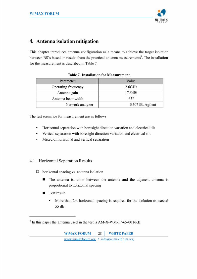
This chapter introduces antenna configuration as a means to achieve the target isolation
between BS’s based on results from the practical antenna measurements8. The installation
for the measurement is described in Table 7.
Table 7. Installation for Measurement
Parameter Value
Operating frequency 2.6GHz
Antenna gain 17.5dBi
Antenna beamwidth 65°
Network analyzer E5071B, Agilent
The test scenarios for measurement are as follows
Horizontal separation with boresight direction variation and electrical tilt
Vertical separation with boresight direction variation and electrical tilt
Mixed of horizontal and vertical separation
4.1. Horizontal Separation Results
horizontal spacing vs. antenna isolation
The antenna isolation between the antenna and the adjacent antenna is
proportional to horizontal spacing
Test result
More than 2m horizontal spacing is required for the isolation to exceed
55 dB.
8In this paper the antenna used in the test is AM-X-WM-17-65-00T-RB.
WiMAX FORUM 28 WHITE PAPER
www.wimaxforum.org • [email protected]

8/8/2019 FDD-TDD Interference Analysis Involving WiMAX Systems Final 091103
http://slidepdf.com/reader/full/fdd-tdd-interference-analysis-involving-wimax-systems-final-091103 29/39
WiMAX FORUM
Figure 9. Antenna isolation vs. horizontal spacing
Antenna boresight angle vs. antenna isolation
Additional isolation can be secured over 0 degree in antenna installation.
Test result
Positive rotation of boresight angle direction can improve the isolation
by more than 10 dB.
Figure 10. Boresight angle vs. antenna isolation
Antenna tilt vs. antenna isolation
It is considered that both antennas have the same electrical down-tilt
Test result
Electrical tilt improves the isolation by 20 dB at 4°downward.
WiMAX FORUM 29 WHITE PAPER
www.wimaxforum.org • [email protected]

8/8/2019 FDD-TDD Interference Analysis Involving WiMAX Systems Final 091103
http://slidepdf.com/reader/full/fdd-tdd-interference-analysis-involving-wimax-systems-final-091103 30/39
WiMAX FORUM
Figure 11. Electrical Down-tilt vs. antenna isolation
4.2. Vertical Separation Results
Vertical spacing vs. antenna isolation
The vertical spacing between the antenna and the adjacent antenna secures
better isolation than horizontal spacing
Test result
Vertical separation provides at least 70dB of isolation even in the case of
0m separation distance.
Figure 12. Vertical isolation vs. antenna isolation
WiMAX FORUM 30 WHITE PAPER
www.wimaxforum.org • [email protected]

8/8/2019 FDD-TDD Interference Analysis Involving WiMAX Systems Final 091103
http://slidepdf.com/reader/full/fdd-tdd-interference-analysis-involving-wimax-systems-final-091103 31/39
WiMAX FORUM
Boresight angle vs. antenna isolation
Test result
Rotation of boresight angle is less effective below 90°
Rotation of boresight angle direction can improve the isolation by only
10 dB in 180° of boresight angle
Figure 13. vertical angle vs. antenna isolation
Antenna tilt vs. antenna isolation
It is considered that both antennas have the same electrical down-tilt
The upper antenna is used for transmitting, the lower antenna for receiving.
Test result
Simultaneous electrical down-tilt of both antennas improves the isolation
by more than 7dB at 4°downward.
Figure 14. Electrical Down-tilt vs. antenna isolation
WiMAX FORUM 31 WHITE PAPER
www.wimaxforum.org • [email protected]

8/8/2019 FDD-TDD Interference Analysis Involving WiMAX Systems Final 091103
http://slidepdf.com/reader/full/fdd-tdd-interference-analysis-involving-wimax-systems-final-091103 32/39
WiMAX FORUM
4.3. Horizontal and vertical separation
Horizontal & vertical spacing vs. antenna isolation
Test result
The isolation for the mixed horizontal and vertical separation is
decreasing with the increase in horizontal separation distance.
But this is better than that in simple horizontal isolation.
This concludes that the mixed of horizontal & vertical separation is more
efficient in case that the use of same antenna pole for both BS’s is not
possible.
Figure 15. Horizontal & vertical spacing vs. antenna isolation
4.4. Result summary
The expected isolation for the antenna configuration is summarized at Table9
. Up to80dB isolation, either horizontal antenna configuration or vertical antenna configuration
9However, the isolation value may be different, depending on the antenna model and the
test environment.
WiMAX FORUM 32 WHITE PAPER
www.wimaxforum.org • [email protected]

8/8/2019 FDD-TDD Interference Analysis Involving WiMAX Systems Final 091103
http://slidepdf.com/reader/full/fdd-tdd-interference-analysis-involving-wimax-systems-final-091103 33/39
WiMAX FORUM
can be applied. Isolation of over 80dB is possible using a vertical antenna configuration.
Table 8. Summary of antenna configuration
Antenna Configuration ExpectedIsolation
Horizontal separation 3m / 8m 56dB / 61dB
Horizontal separation 3m
with 0°/ +15° boresight angle rotation56dB / 60dB
Horizontal separation 3m with 0°/ 4°electrical down-tilt 56dB / 76dB
Vertical separation 0m 70dB
Vertical separation 1m with different antenna pole
(horizontal separation 1m) 76dB
Vertical separation 0.5m with 0°/ 4°electrical down-tilt 76dB / 83dB
4.5. Result analysis
EC Decision 2008/477/EC [2] defines a 2.5GHz BEM and the associated co-existence
condition between FDD and TDD systems in adjacent blocks. This BEM requires a
baseline out of block emission level of -45dBm/MHz across BS receive parts of the band
(See Annex A)
Our SLS demonstrates that the necessary inter-system isolation value is 107.82dB (FRP1)
and 109.62dB (FRP3) which relate to allowable interference levels of -116.4dBm/MHz
(FRP1, I/N = -7.4dB) and -118.2dBm/MHz (FRP3, I/N = -9.2dB) at a victim BS receiver
to ensure uplink capacity loss less than 3% of capacity loss without ACI.
WiMAX FORUM 33 WHITE PAPER
www.wimaxforum.org • [email protected]

8/8/2019 FDD-TDD Interference Analysis Involving WiMAX Systems Final 091103
http://slidepdf.com/reader/full/fdd-tdd-interference-analysis-involving-wimax-systems-final-091103 34/39
WiMAX FORUM
For co-sited BS’s, the interference budget is as follows:
SLS derived maximum allowable interference density: -118.2 dBm/MHz
BEM derived out of band power density: -45-17 (antenna gain) = -62dBm /MHz
Measured isolation provided by antenna separation: at least 56dBWorst case power density in victim band: -62-56dBm/MHz=118dBm/MHz
Resultant interference margin: 118-118.2=-0.2 dB.
This low margin illustrates that BS co-siting is possible, since horizontal/vertical antenna
separation can provide at least 56dB of inter-BS isolation under reasonable conditions.
Angle twist can be used to further reduce the received interference level and increase the
margin even further.
WiMAX FORUM 34 WHITE PAPER
www.wimaxforum.org • [email protected]

8/8/2019 FDD-TDD Interference Analysis Involving WiMAX Systems Final 091103
http://slidepdf.com/reader/full/fdd-tdd-interference-analysis-involving-wimax-systems-final-091103 35/39
WiMAX FORUM
5. Conclusion
This white paper analyses the potential to avoid interference between co-sited 2.6GHz
TDD and FDD systems in the context of the European Decision 2008/477/EC [2]. The
paper recognises that the BS to BS interference scenario presents the greatest challenge
out of the possible inter-system interference scenarios.
The study and measurement campaign have confirmed that sufficient isolation can be
achieved between co-sited FDD-TDD BS’s that are operating in adjacent spectrum blocks
and complying with the BEM baseline out of block emission requirements.
The implications of these results are particularly helpful to ease deployment challenges in
dense areas where BS sites maybe at a premium or where environmental aspects lead to
encouragement for site sharing amongst operators.
WiMAX FORUM 35 WHITE PAPER
www.wimaxforum.org • [email protected]

8/8/2019 FDD-TDD Interference Analysis Involving WiMAX Systems Final 091103
http://slidepdf.com/reader/full/fdd-tdd-interference-analysis-involving-wimax-systems-final-091103 36/39
WiMAX FORUM
ANNEX A. Block Edge Mask identified in EC
Decision (2008/477/EC)
The European Commission published Decision 2008/477/EC [1] to harmonize use of the
band 2500~2690MHz under common ‘least restrictive’ technical conditions across the
European Union member states.
.It adopts a Block Edge Mask to regulate emission requirements in the entire
2500~2690MHz band in the absence of bilateral or multilateral agreements between
neighboring networks. The BEM consists of ‘Baseline requirements’ specified as out-of-
block emission levels and ‘Block specific requirements’ specified as out-of-block emission levels within 5MHz frequency outside the assigned block edges. Finally,
‘Restricted Block’ usage (of the guard channel) is identified that requires further specific
constraints that maybe applicable to BS’s placed indoors or where the antenna height of
BS is below a certain height.
In the unrestricted usage scenario for BS’s, the baseline requirement is +4dBm/MHz in
the frequency range which is allocated to FDD downlink ±5MHz. At all other
frequencies in the band 2500~2690MHz not covered by the definition above, the baseline
requirement is -45dBm/MHz. The baseline requirements for BS out-of-block emissions
are illustrated in Figure A-1.
Figure A-1. Baseline requirements of the block edge mask
Block specific requirement for BS in-band is +61dBm/5MHz (in-block EIRP). Block
WiMAX FORUM 36 WHITE PAPER
www.wimaxforum.org • [email protected]

8/8/2019 FDD-TDD Interference Analysis Involving WiMAX Systems Final 091103
http://slidepdf.com/reader/full/fdd-tdd-interference-analysis-involving-wimax-systems-final-091103 37/39
WiMAX FORUM
specific requirements for BS just outside the assigned block are detailed in Table A-.
Table A-1. Block specific requirements for BS out-of-block in unrestricted band
(Symmetric)Frequencies (Upper Edge) Maximum mean EIRP
0.0 to 0.2 MHz + 3 dBm/30kHz
0.2 to 1.0 MHz + 3 – 15(†Δf– 0.2) dBm/30kHz
1.0 to 5.0 MHz + 4 dBm/MHz
†Δf is the frequency offset from the relevant block edge (MHz)
A 5MHz guard block needs to be identified between FDD operation and adjacent TDD
operation which can alternatively be used in compliance with the requirements of therestricted block as detailed in Figure A-2. Therefore, interference from a TDD BS is
restricted to below -45dBm/MHz in FDD UL band. Interference from FDD BS is
restricted as below -45dBm/MHz in TDD band adjacent to FDD DL
Figure A-2. Restricted block edge mask for BS
In the restricted block for BS’s, block specific requirement for BS in-band is
+25dBm/5MHz. Block specific requirement for BS out-of-band is limited like Table A-.
WiMAX FORUM 37 WHITE PAPER
www.wimaxforum.org • [email protected]
8/8/2019 FDD-TDD Interference Analysis Involving WiMAX Systems Final 091103
http://slidepdf.com/reader/full/fdd-tdd-interference-analysis-involving-wimax-systems-final-091103 38/39
WiMAX FORUM
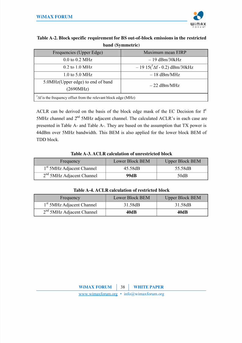
Table A-2. Block specific requirement for BS out-of-block emissions in the restricted
band (Symmetric)
Frequencies (Upper Edge) Maximum mean EIRP
0.0 to 0.2 MHz – 19 dBm/30kHz0.2 to 1.0 MHz – 19 15(
†Δf - 0.2) dBm/30kHz
1.0 to 5.0 MHz – 18 dBm/MHz
5.0MHz(Upper edge) to end of band
(2690MHz) – 22 dBm/MHz
†Δf is the frequency offset from the relevant block edge (MHz)
ACLR can be derived on the basis of the block edge mask of the EC Decision for 1st
5MHz channel and 2
nd
5MHz adjacent channel. The calculated ACLR’s in each case are presented in Table A- and Table A-. They are based on the assumption that TX power is
44dBm over 5MHz bandwidth. This BEM is also applied for the lower block BEM of
TDD block.
Table A-3. ACLR calculation of unrestricted block
Frequency Lower Block BEM Upper Block BEM
1st
5MHz Adjacent Channel 45.58dB 55.58dB
2nd
5MHz Adjacent Channel 99dB 50dB
Table A-4. ACLR calculation of restricted block
Frequency Lower Block BEM Upper Block BEM
1st
5MHz Adjacent Channel 31.58dB 31.58dB
2nd
5MHz Adjacent Channel 40dB 40dB
WiMAX FORUM 38 WHITE PAPER
www.wimaxforum.org • [email protected]

8/8/2019 FDD-TDD Interference Analysis Involving WiMAX Systems Final 091103
http://slidepdf.com/reader/full/fdd-tdd-interference-analysis-involving-wimax-systems-final-091103 39/39
WiMAX FORUM
About the WiMAX Forum ®
The WiMAX Forum
®
is an industry-led, not-for-profit corporation formed to promote andcertify the compatibility and interoperability of broadband wireless products using the IEEE802.16 and ETSI HiperMAN wireless MAN specifications. The WiMAX Forum’s goal is toaccelerate the introduction of these devices into the marketplace. WiMAX Forum Certified™products are interoperable and support Metropolitan Broadband Fixed, Nomadic and MobileApplications.
For more information about the WiMAX Forum and its activities, please visitwww.wimaxforum.org.
Notice and Disclaimer.
The statements and viewpoints in this white paper are those of the WiMAX Forum as of the release date noted on the coverpage (the “Release Date”). Except as expressly stated, they may not reflect the views of individual WiMAX Forummembers. The WiMAX Forum has endeavoured to provide information that is current and accurate as of the Release Date
but it does not warrant that all information is complete and error-free. Nor does it undertake to update this white paperbased upon new information and developments, though it may elect to do so in its sole discretion and without notice. Allinformation in this white paper is provided on an “AS IS” basis. The WiMAX Forum disclaims all express and impliedwarranties relating to the contents of this white paper.
The WiMAX Forum has not investigated or made an independent determination regarding title or noninfringement of anytechnologies that may be described or referenced in this white paper. Persons seeking to implement such technologies aresolely responsible for making all assessments relating to title and noninfringement of any technology, standard, orspecification referenced in this document and for obtaining appropriate authorization to use such technologies, standards,and specifications, including through the payment of any required license fees.