FC5A-F2M2 PID Card – Setup and local loopback...
7
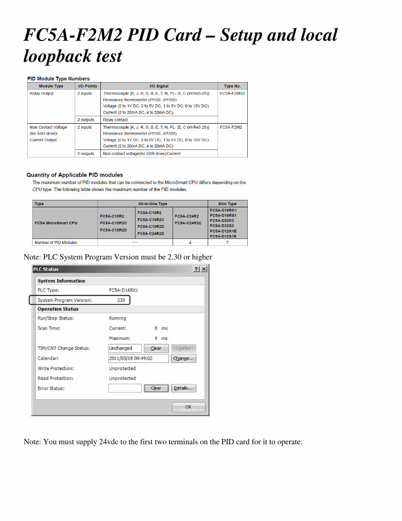
FC5A-F2M2 PID Card – Setup and local loopback test Note: PLC System Program Version must be 2.30 or higher Note: You must supply 24vdc to the first two terminals on the PID card for it to operate.
Transcript of FC5A-F2M2 PID Card – Setup and local loopback...
FC5A-F2M2 PID Card – Setup and local
loopback test
Note: PLC System Program Version must be 2.30 or higher
Note: You must supply 24vdc to the first two terminals on the PID card for it to operate.

Local Loop-back Connections (for self testing, 4-20ma mode)
No external devices required, just the PLC and the PID card.
Install the following Jumpers to test both channels (see diagram below)
IN0 +’ to OUT0 +
IN0 B’- to OUT0 -
IN1 +’ to OUT1 +
IN1 B’- to OUT1 -
Enter the logic below in WindLDR.
When M0100 is turned ON in WindLDR’s monitor mode, both PID channels are enabled and operational.
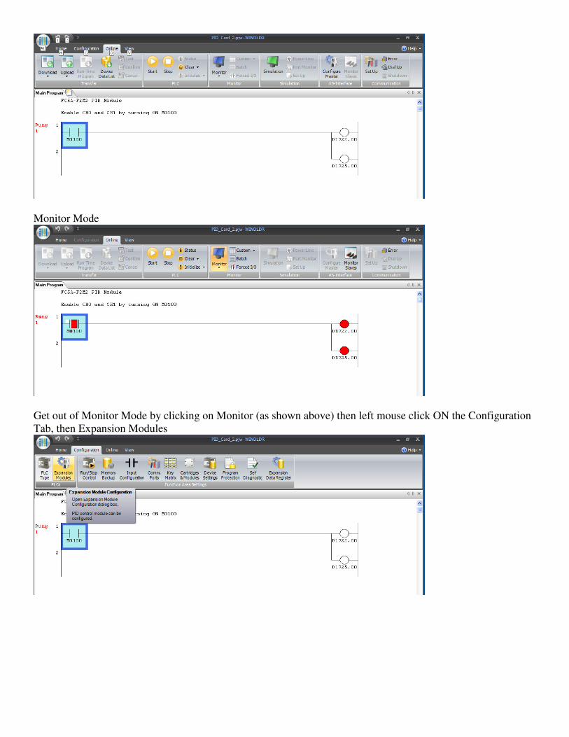
Monitor Mode
Get out of Monitor Mode by clicking on Monitor (as shown above) then left mouse click ON the Configuration
Tab, then Expansion Modules

Select the quantity of modules,
in this example 1,
Then select the PID module type, in this example the FC5A-F2M2.
Click ON the Configuration Parameters button, the display below will appear.
Select 4-20ma for the input range.

400 for Linear.Conversion Maximum Value
0 for Linear Conversion Minimum Value
Click ON Control Parameters Button (CH0)
Enter the settings below
Do the same for CH1
Enter the same settings for CH1 as for CH0
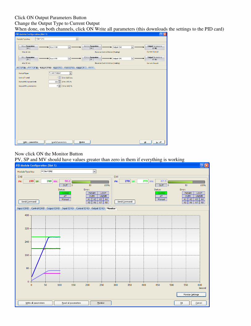
Click ON Output Parameters Button
Change the Output Type to Current Output
When done, on both channels, click ON Write all parameters (this downloads the settings to the PID card)
Now click ON the Monitor Button
PV, SP and MV should have values greater than zero in them if everything is working

You can click ON Monitor Settings to select different scale range, scale timing and pen color options
End-of-file