Fatigue Essentials User Guide 1 - appliedcax.com · Importing data from Femap The user is also...
31
Page 1 | 31 FATIGUE ESSENTIALS USER GUIDE 1.0 User Guide
-
Upload
trannguyet -
Category
Documents
-
view
248 -
download
3
Transcript of Fatigue Essentials User Guide 1 - appliedcax.com · Importing data from Femap The user is also...

P a g e 1 | 31
FATIGUE ESSENTIALS USER GUIDE 1.0
User Guide

P a g e 2 | 31
FATIGUE ESSENTIALS USER GUIDE 1.0
Contents Introduction ............................................................................................................................................................................ 3
The Project Info Editor ............................................................................................................................................................ 7
The Load Case Editor ............................................................................................................................................................... 8
The Spectrum Editor ............................................................................................................................................................. 11
The Material Editor ............................................................................................................................................................... 12
The Analysis Editor ................................................................................................................................................................ 16
The Femap Interface ............................................................................................................................................................. 18
Example 1 – Classical Fatigue ................................................................................................................................................ 19
Example 2 – Using the Femap Interface ............................................................................................................................... 24
P a g e 3 | 31
FATIGUE ESSENTIALS USER GUIDE 1.0
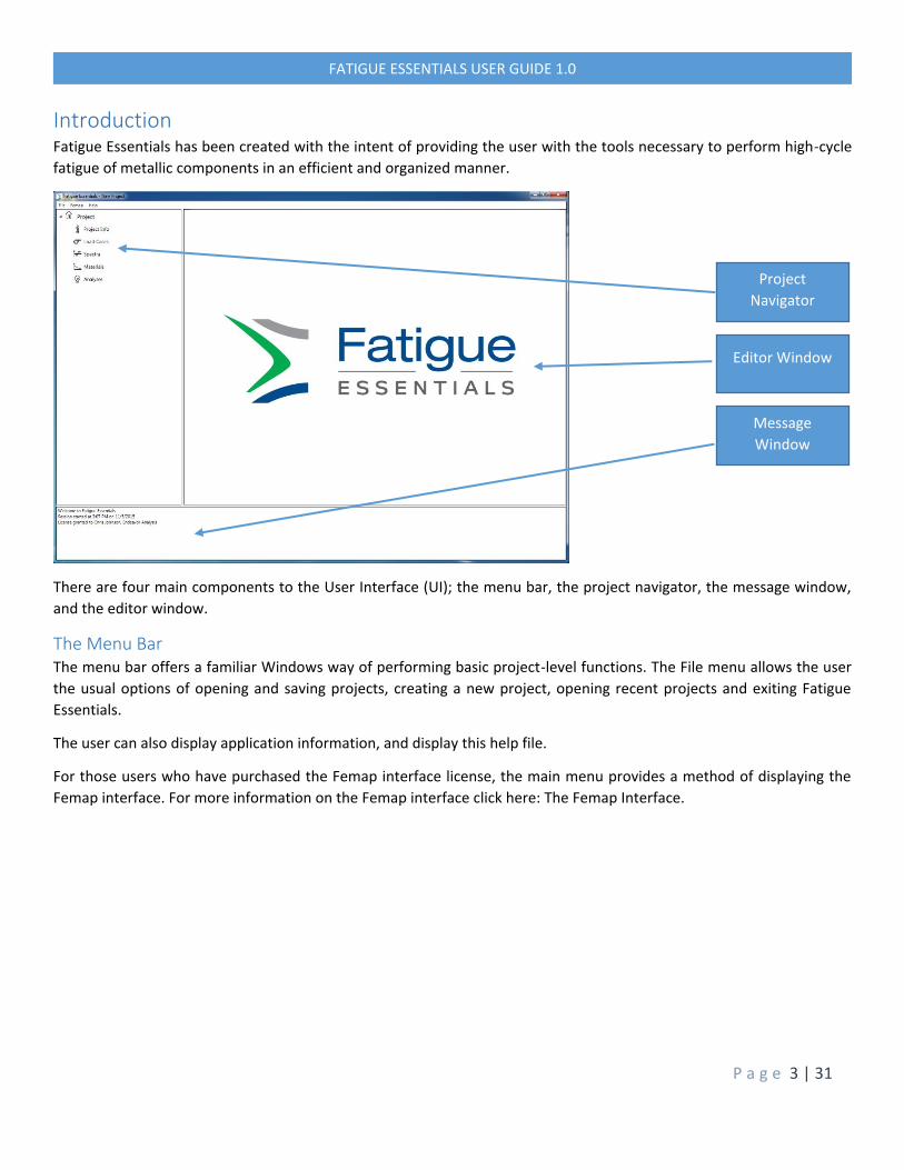
Introduction Fatigue Essentials has been created with the intent of providing the user with the tools necessary to perform high-cycle
fatigue of metallic components in an efficient and organized manner.
There are four main components to the User Interface (UI); the menu bar, the project navigator, the message window,
and the editor window.
The Menu Bar The menu bar offers a familiar Windows way of performing basic project-level functions. The File menu allows the user
the usual options of opening and saving projects, creating a new project, opening recent projects and exiting Fatigue
Essentials.
The user can also display application information, and display this help file.
For those users who have purchased the Femap interface license, the main menu provides a method of displaying the
Femap interface. For more information on the Femap interface click here: The Femap Interface.
Project
Navigator
Editor Window
Message
Window

P a g e 4 | 31
FATIGUE ESSENTIALS USER GUIDE 1.0
The Project Navigator
The project navigator is the primary tool for navigating between all the various project elements such as load cases,
materials and analyses, and provides the functionality for all element creation, modification and deletion.
When Fatigue Essentials is first started, the navigator will look like the figure above. As the user adds more elements to
the project the navigator updates its tree structure to reflect the changes. As the user hovers the mouse over the various
tree entries, buttons are displayed according to which actions are available to the user. Hovering over each button will
display a tool tip to indicate what function the button performs.
Button Icon Found in… Purpose
Project Root Close any existing database and opens a new one
Project Root Load Case Root Spectra Root Materials Root
Opens an existing database from a file Imports load case / stress detail data from a file Imports spectrum data from a file Imports a material library file
Project Root Material Root
Saves the database to a file Saves the material data to a file
Project Root Saves the database under a new file name
Multiple locations Opens the selected Navigator item in the Editor Window
Multiple locations
Adds a new item. In a table this button appends an item to the bottom of the table
Multiple locations Deletes an item, or deletes the selected item in a table
Tables Inserts a row above the selected row

P a g e 5 | 31
FATIGUE ESSENTIALS USER GUIDE 1.0
The Message Window
The message window provides visual feedback to the user to inform of changes to the database, warnings, and errors
(should they occur). Hovering over the window will also display two buttons to allow the user to clear the window
contents, or to copy the contents to the clipboard.

P a g e 6 | 31
FATIGUE ESSENTIALS USER GUIDE 1.0
The Editor Window The editor window is contextual, and its content changes according to what the user wishes to do. Regardless of which
specific editor is open, each editor acts in a similar manner. When an editor is opened, the editor content is displayed in
the main area of the editor window, and a toolbar is displayed below. Changes made in the editor can either be committed
to the project database by selecting the ‘Apply’ button, or disregarded by selecting the ‘Cancel’ button.
To learn more about the various editor windows, click on one of the following links:
The Project Info Editor
The Load Case Editor
The Spectrum Editor
The Material Editor
The Analysis Editor
The Femap Interface

P a g e 7 | 31
FATIGUE ESSENTIALS USER GUIDE 1.0
The Project Info Editor
The Project Information Editor provides the user with the ability to attach traceable information to the project database;
which engineers were involved and when the work was performed, and also general project information such as customer
and project names can be entered here.

P a g e 8 | 31
FATIGUE ESSENTIALS USER GUIDE 1.0
The Load Case Editor
The load case editor provides the user with the capability to enter both stress detail information and load case data. Data
can be entered in one of three ways:
1. Manual line-by-line entry
2. Importing data from an external file (Comma Separated Variable .csv file)
3. Importing the data from Femap
Manual data entry The left hand side of the editor allows the user to manually create stress details, such as blend radii, grease holes, thread
undercuts etc. There must always be one stress detail in the project, but there can be (in theory, depending on hardware)
as many details as the user requires.
Adding, modifying or deleting stress details is performed by hovering over an appropriate detail in the table. This will
display buttons in the individual table row entry which allow the addition, insertion or deletion of an individual row in the
table.
Note that this behavior is perpetuated throughout the application; whenever a table is used for the display and
modification of project data, similar behavior will be presented to the user.
Adding load cases works in a similar manner. Whenever a user selects a stress detail the appropriate stresses are then
reflected for each load case in the table on the right of the editor.

P a g e 9 | 31
FATIGUE ESSENTIALS USER GUIDE 1.0
Importing data from an external file The user can import data from an external application using a comma separated variable file (*.csv file). The file format
(which must be adhered to otherwise errors will occur), is as follows:
If the file format is suitable, Fatigue Essentials will create stress details and load cases from the imported data.
File format for Importing Load Cases and Stress Details
The first row of the csv file is in the format:
IDs,comment,detailname1,detailname2,…
Note that the ‘IDs’ field never changes, and if the comment field is blank then there must still be two sequential commas:
IDs,,detailname1,detailname2,…
Each subsequent row then takes the following format:
id,comment,stress1,stress2,…
Again, if the there are no comments for the load case, there must be two sequential commas. An example csv file could
contain the following:
IDs,,Node_1000,Node_1001,Node_1003
101,,56.0,43.8,72.2
102,,-14.0,-2.8,-64.9
103,Max_Vertical_Reaction,102.0,128.0,86.7

P a g e 10 | 31
FATIGUE ESSENTIALS USER GUIDE 1.0
File Format for Importing Spectrum Data
Admittedly the spectrum csv file format is not a true csv file. The file format is as follows:
Spectrum
spectrum_name
spectrum_repeats
load_case_id,block_id,block_repeats
...
This sequence can be repeated for multiple spectra. The following is an example of a spectrum file:
Spectrum
Simple_Repeating_Spectrum
50000
101,1,1
103,1,1
101,1,1
101,2,10
102,2,10
101,2,10
102,3,5
103,3,5
102,3,5
Spectrum
High_Cycle_Spectrum
5000000
101,1,1
102,1,1
101,1,1
Importing data from Femap The user is also capable of importing data from Femap. To learn more about the Femap interface see Example 2 – Using
the Femap Interface.

P a g e 11 | 31
FATIGUE ESSENTIALS USER GUIDE 1.0
The Spectrum Editor
The Spectrum Editor allows the user to define the sequence of loads applied to the stress details, and provides visual
feedback of the spectrum to the user.
The user can enter a name for the spectrum, and specify how many times the entire spectrum is repeated.
The entry form is the familiar Fatigue Essentials tabular format (the user can append, insert and delete tabular entries),
and each row in the data table consists of a load case selection, a block ID and block repeat count. Spectrum repeats can
be entered at the top of the editor, and by clicking on the ‘Display Spectrum’ checkbox and selecting a stress detail in the
drop-down menu a visual representation of the spectrum for each stress detail can be entered.
The load case block IDs allow the user to break a spectrum into manageable sections; for instance in the spectrum shown
in the figure above, load cases 7 & 8 are grouped into a block (ID = 2) and this block is then repeated 10 times. This creates
the oscillating middle part of the spectrum, which means the user does not have to specify all of the loads manually.

P a g e 12 | 31
FATIGUE ESSENTIALS USER GUIDE 1.0
The Material Editor
General Material Data On the left-hand side of the editor the user can enter general material information, for example material name, temper,
form (longitudinal, transverse etc.), any material notes and so on.
Most of this is strictly for reference purposes only (including the Kt field which is not used in any fatigue calculations, in
this case the Kt refers to the coupon shape used for testing), however the Fty and Ftu fields are used if the S-N curve is
defined using the strength data, or the mean stress correction factor is set to ‘Modified Goodman’. The ‘Units’ field is also
used in the fatigue calculations, and is resolved against the units specified in the Analysis Editor.
The ‘Reference’ and ‘Type’ fields are used to build a hierarchical tree under the Material item in the Project Navigator;
this allows the user to organize their material library. At this time only two levels of hierarchy are permitted.

P a g e 13 | 31
FATIGUE ESSENTIALS USER GUIDE 1.0
S-N Curve Definition There are three options for defining the S-N curve; using a Walker equation, tabular input, or estimating from strength
data (again in tabular form).
Walker Equation Definition A Walker equation S-N curve form can be used if the user has available data, such as that provided in Metallic Materials
Properties Development and Standardization (MMPDS, or formerly Mil-HDBK-5):
Tabular Input Definition The user can enter S-N data in tabular format as a series of cycles-to-failure vs stress pairs. This is the most flexible way of
entering data as any shape of curve can be entered and equations are not required.
The table works in the same manner as the other tables in Fatigue Essentials, and the user can append, insert or delete
rows as necessary.

P a g e 14 | 31
FATIGUE ESSENTIALS USER GUIDE 1.0
Estimating S-N Curve from Strength Data The user can also input a value for Ftu, and then use this to define an S-N curve. This is used when no other data is available.
Using a value equivalent to the tensile yield stress for 1000 cycles and 50% of Ftu at 1,000,000 cycles will provide a
reasonable mean curve for most metallic materials. Extending the curve out to higher cycles with a third point with an
endurance limit or slightly decreasing slope is up to the user’s discretion.
Again the familiar table format is used:
Mean Stress Correction Factor The user also has the option to define which Mean Stress Correction Factor (if any) is used in the analysis. The user can
select an option from the drop-down menu, and then any necessary parameters are entered in the fields below:
If a mean stress correction factor is used, additional curves representing R-ratio values of -1.0, 0.0 & 0.25 are displayed in
the chart. For example the figure below shows a set of Walker Equation curves (A = 12.0, B = 3.75, SEnd = 80.0, R = -0.5),
using a Walker Mean Stress Correction Factor (Gamma = 0.5).

P a g e 15 | 31
FATIGUE ESSENTIALS USER GUIDE 1.0
Notes on Mean Stress Correction Types
No Mean Stress Correction The ‘none’ option is available if the user is doing analysis on something similar to an ASME boiler analysis where the curves
are not meant to be adjusted for mean cyclical stress.
Modified Goodman This is the most well-known mean stress correction factor, and has been used for many years.
Smith-Watson-Topper The Smith-Watson-Topper mean stress correction is a good general method to use for metallic materials and is typically
more representative of test data in comparison to the Modified Goodman approach.
Walker The Walker mean stress correction is similar to the Smith-Watson-Topper method, but allows the equation to be ‘tuned’
to available test data using the gamma parameter. If data at multiple stress ratios is not available it is best to use the
Smith-Watson-Topper method.

P a g e 16 | 31
FATIGUE ESSENTIALS USER GUIDE 1.0
The Analysis Editor
The Analysis Editor allows the user to define the parameters of a Fatigue Analysis, and then run the analysis to examine
the results. The user enters or selects the inputs on the left-hand side; most of the inputs are self-explanatory. The
Modification Factors table is (again) in the familiar Fatigue Essentials format. Once you apply changes to create the
analysis, you can then run the fatigue calculations.
The available cycle counting methods are all per ASTM-1049. If the sequence of cases is unknown or random, using peak
counting will combine the cycles in the most conservative manner and should be used if the user is not sure of the exact
loading sequence.
Rainflow counting is the most recognized method of cycle counting. In general the Repeating Rainflow method is a good
choice if the spectrum is repeated and there is confidence in the load case sequence. The standard Rainflow method
should be used if the user wants to string spectrums together and Rainflow the entire sequence. Results between the two
Rainflow methods should in most cases be similar. A Range Pair method has also been included if the user prefers this
method.
The modification factors are a multiplier to the stress (or loads) entered into the Load Case Editor to account for any
fatigue debits (knockdowns in performance for surface finish, surface treatments etc.). Similar to adding a stress
concentration (Kt) to a structural detail, this can be added here as a multiplier to the entered stresses.
Another potential use is to enter loads into the Load Case Editor, and use a modification factor to transform those loads
into stresses prior to cycle counting.
The total cumulative modification factor is displayed above the modification factor table.
The Scatter Factor is a multiplier on the spectrum itself. If a mean S-N curve is being used it is recommended that a scatter
factor of at least five be used to ensure that the analysis is not too optimistic. The Scatter Factor provides a generic
‘adjustment’ to account for material scatter. If the S-N curve is representative of the desired statistical reliability required,
then a scatter factor of one may be used.

P a g e 17 | 31
FATIGUE ESSENTIALS USER GUIDE 1.0
Examining the Results When the user clicks on the ‘Solve Analysis’ button, the fatigue calculations are run, and if successful the results will appear
in the right-hand side of the editor. The top table lists the stress details with the highest damages in descending order.
The bottom table allows the user to examine which cycles are contributing the most to the total damage.
The drop-down menus below the data tables allow the user to select which stress detail to examine, and how many stress
pairs to show. There are also two buttons that allow the user to capture the contents of the analysis editor as a bitmap to
the clipboard, or to write the analysis data to a report in html format.

P a g e 18 | 31
FATIGUE ESSENTIALS USER GUIDE 1.0
The Femap Interface Selecting the Femap Interface menu option will open the Femap Interface, which is shown below.
To select data from Femap, ensure that the correct element option is displayed (i.e. solid or plate element), and then click
on the ‘Select data’ button. Femap will then be shown as the topmost window, and provide the user with prompts to
select the desired output and node sets. Once these have been selected, Fatigue Essentials will create all the required
stress detail and load cases to allow the user to perform fatigue analysis on the Femap model.
Once an analysis has been successfully performed, the user can then export the damage back to Femap using the ‘Export
data’ button.
For more information on the process involved, see Example 2 – Using the Femap Interface
Import data
from Femap
Select element
type
Select stress
type
Select an
analysis
Export data to
Femap

P a g e 19 | 31
FATIGUE ESSENTIALS USER GUIDE 1.0
Example 1 – Classical Fatigue
Step 1 – Define the model This example will walk the user through the fatigue analysis of a simple cantilevered beam of circular cross section.
Classical analysis has determined the stresses at a blend radius on the inner diameter of the beam as follows:
Load Case ID Stress
1 0
2 80
3 50
4 110
5 -40
6 20
Step 2 – Create the load case and stress details Open up the Load Case and Stress Detail Editor, and set up the two table to look similar to the following:

P a g e 20 | 31
FATIGUE ESSENTIALS USER GUIDE 1.0
Step 3 – Create a spectrum Open up the Spectrum Editor, and create a spectrum similar to the following:
Click Apply to create the spectrum in the database.

P a g e 21 | 31
FATIGUE ESSENTIALS USER GUIDE 1.0
Step 4 – Create a Material For the purposes of this analysis, a material representing a generic and/or highly-fictional high-strength steel will be
created. Data will be entered in tabular format, and a Smith-Watson-Topper mean stress correction will be used. Open up
the material editor, give the material a name and enter suitable names for the ‘Reference’ and ‘Type’ fields. Select ‘ksi’ as
the units.
No data needs to be entered for Fty and Ftu, as they are only used for S-N curves estimated from strength data, or when
using the Modified Goodman mean stress correction factor.
Select ‘Tabulated’ as the S-N curve definition type, and then set up the table to look like the following:
Cycles to Failure Stress
1 232.0
10 219.2
100 206.4
840 193.6
2500 149.8
25000 90.4
100000 72.3
250000 61.8
1000000 48.8
10000000 35.1
100000000 28.1
Finally, select Smith-Watson-Topper’ in the drop-down menu. The material is now fully defined, and can be added to the
database using the ‘Apply’ button.
If desired, click on the ‘Show Chart’ check box to display a visual representation of the S-N curves:

P a g e 22 | 31
FATIGUE ESSENTIALS USER GUIDE 1.0
Step 5 – Set Up the Analysis First enter a name for the analysis, and enter a scatter factor of 5.
Then select the spectrum created in step 3, the material created in step 4, select ‘ksi’ as the units, and ‘Rainflow’ as the
cycle counting method. More than 50 stress pairs can be retained if required, but this can hamper performance if too
many cycles are retained.
Now add some modification factors:
Modification Factor Name Factor
Shot peen 0.85
Chrome plating 1.24
Heat Treat 0.97
The analysis is now defined, and can be added to the database by clicking on the ‘Apply’ button.

P a g e 23 | 31
FATIGUE ESSENTIALS USER GUIDE 1.0
Step 6 – Run the analysis Once the analysis has been created, the ‘Solve Analysis’ button is enabled. Simply click the button to run the analysis, and
in a short time the results will be displayed in the left-hand side of the editor.
It can be seen that the stress detail has a damage of 1.0, therefore a crack has been initiated.
In the analysis editor, reduce the scatter factor to 3, apply changes, and re-run the analysis. It can be seen that by reducing
the scatter factor applied to the analysis from 5 to 3 means that no crack initiation is expected at the stress detail being
studied, though your statistical confidence and reliability has been reduced.
Step 7 – Write an Html report To write the data to an html file, simply click on the button at the bottom right of the editor window, and select a suitable
file name. This html file can then be imported into other programs for formatting, printed to pdf etc.
An alternative is to use the ‘Capture screenshot button’, and paste the data from the clipboard directly into the fatigue
analysis report.
Congratulations, you’ve just completed your first classical fatigue analysis using Fatigue Essentials!

P a g e 24 | 31
FATIGUE ESSENTIALS USER GUIDE 1.0
Example 2 – Using the Femap Interface This example will analyze the fatigue performance of a simple square plate with a hole undergoing a simple oscillating
tension load. The file can be found in the Fatigue Essentials installation directory under
‘/Samples/Plate_With_Hole.modfem’.
Make sure that both Fatigue Essentials is running, and that the plate model is open in Femap.

P a g e 25 | 31
FATIGUE ESSENTIALS USER GUIDE 1.0
Step 1 – Import the data from Femap Open the Femap interface using the main menu. Then select the ‘Plate – Top and Bottom’ option in the drop-down menu,
and click the ‘Select data from Femap button’.
Femap will be set as the top window, and the user will be prompted to select output and node sets of interest. For the
purposes of this exercise, the user can simply select ‘All’ for both. Once this is done, Fatigue Essentials will create the
necessary stress details and load cases.
Click!

P a g e 26 | 31
FATIGUE ESSENTIALS USER GUIDE 1.0
Step 2 – Examine the imported data Open the Load Case Editor, and ensure it looks similar to the following:
If desired, the user can select stress details to examine the nodal stresses for each load case.

P a g e 27 | 31
FATIGUE ESSENTIALS USER GUIDE 1.0
Step 3 – Create a spectrum.
Open the spectrum editor. For this example we are going to create a simple reversing spectrum with 1 cycle. Add two
additional lines to the table on the left, and then make sure that they look similar to the figure shown above. Display the
spectrum using the check box to ensure that the spectrum looks correct. Apply the changes to add the spectrum to the
database.

P a g e 28 | 31
FATIGUE ESSENTIALS USER GUIDE 1.0
Step 4 – Create a material
Open the material editor. Set up the material as shown in the figure above; for clarity the S-N curve data is repeated in
the table below:
Cycles to Failure Stress
1 232000
10 219200
100 206400
840 193600
2500 149800
25000 90400
100000 72300
250000 91800
1000000 48800
10000000 35100
100000000 28100
Click ‘Apply’ to create the material.

P a g e 29 | 31
FATIGUE ESSENTIALS USER GUIDE 1.0
Step 5 – Set up the analysis Open the analysis editor. The loads data imported from Femap, spectrum created in Step 3 and the material used in Step
4 will now all be used to calculate the actual fatigue performance of the part. Set up the editor window to look like the
following:
Click apply to create the analysis. The ‘Solve Analysis’ button should now be available.

P a g e 30 | 31
FATIGUE ESSENTIALS USER GUIDE 1.0
Step 6 – Run the Analysis Click ‘Solve Analysis’ to run the cycle counting. When the analysis has finished, the output will be displayed in the right
hand side of the editor window. The top half shows a summary of the nodal damages, sorted by damage magnitude. The
lower half allows the user to display cycle count data for the stress detail specified in the drop-down menu.

P a g e 31 | 31
FATIGUE ESSENTIALS USER GUIDE 1.0
Step 7 – Send the fatigue results to the Femap model Re-open the Femap interface using the main menu item. Select the analysis created in Step 8, and click the ‘Send to Femap’
button.
This should then display the Femap output shown in the figure below:
Congratulations, you’ve just performed your first fatigue analysis on a Femap model!
Click!