Fatigue Analysis of Welded Structures Using nCode DesignLife
23
Fatigue Analysis of Welded Structures Using nCode DesignLife Dr Peter Heyes - HBM UK Ltd Altair EHTC, Versailles, Oct 27-29 2010
Transcript of Fatigue Analysis of Welded Structures Using nCode DesignLife
Fatigue Analysis of Welded Structures
Using nCode DesignLife
Dr Peter Heyes - HBM UK Ltd
Altair EHTC, Versailles, Oct 27-29 2010
Agenda
• What is DesignLife?
• Fatigue analysis methods for welded structures
• “Volvo” method
• Stress recovery methods for welds and mesh sensitivity
• Validation and application
• Concluding remarks
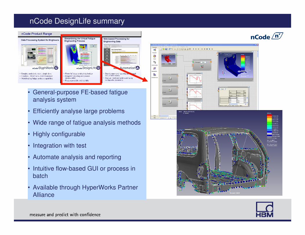
nCode DesignLife summary
• General-purpose FE-based fatigue
analysis system
• Efficiently analyse large problems
• Wide range of fatigue analysis methods
• Highly configurable
• Integration with test
• Automate analysis and reporting
• Intuitive flow-based GUI or process in
batch
• Available through HyperWorks Partner
Alliance
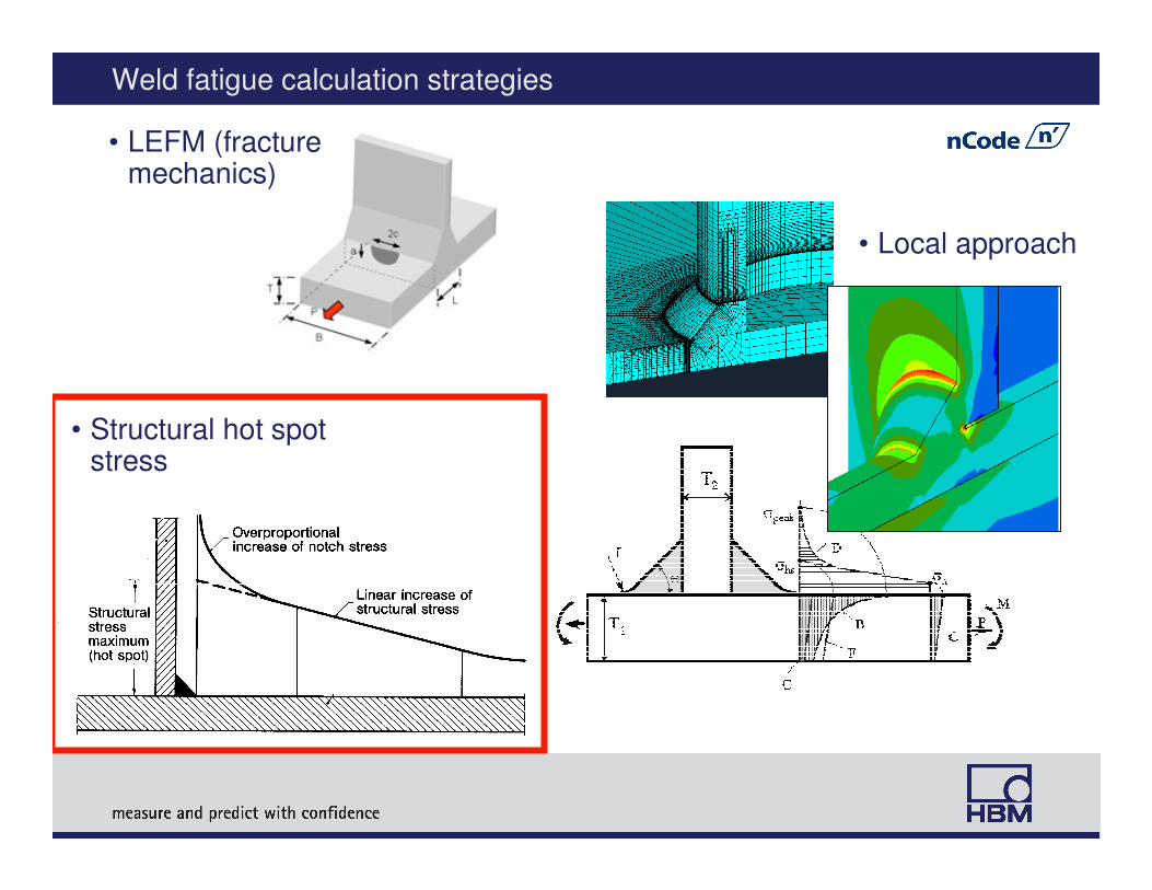
Weld fatigue calculation strategies
• Local approach
• LEFM (fracture mechanics)
• Structural hot spot stress
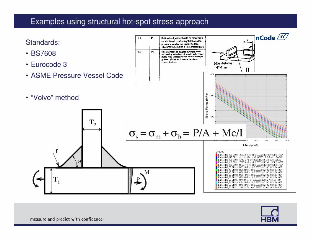
Examples using structural hot-spot stress approach
Standards:
• BS7608
• Eurocode 3
• ASME Pressure Vessel Code
• “Volvo” method
r
T1
T2
σs = σm + σb = P/A + Mc/I
P
M
Θ
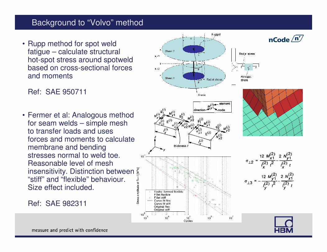
Background to “Volvo” method
• Rupp method for spot weld fatigue – calculate structural hot-spot stress around spotweldbased on cross-sectional forces and moments
Ref: SAE 950711
• Fermer et al: Analogous method for seam welds – simple mesh to transfer loads and uses forces and moments to calculate membrane and bending stresses normal to weld toe. Reasonable level of mesh insensitivity. Distinction between “stiff” and “flexible” behaviour. Size effect included.
Ref: SAE 982311
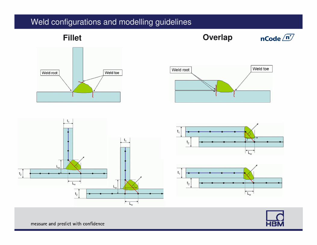
Weld configurations and modelling guidelines
OverlapFillet
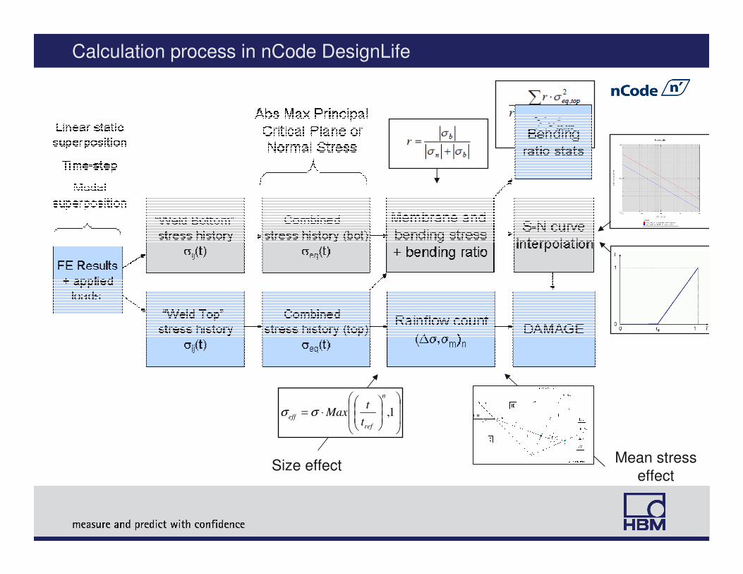
Calculation process in nCode DesignLife
Size effectMean stress
effect
⋅= 1,
n
ref
efft
tMaxσσ
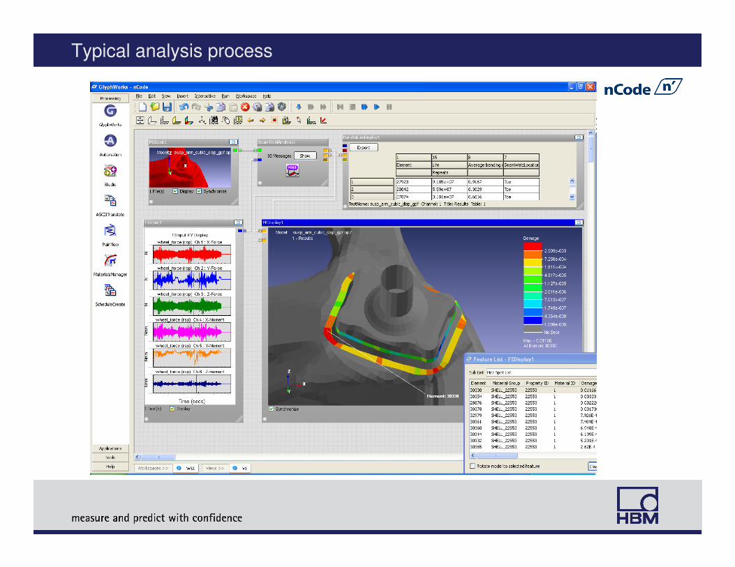
Typical analysis process
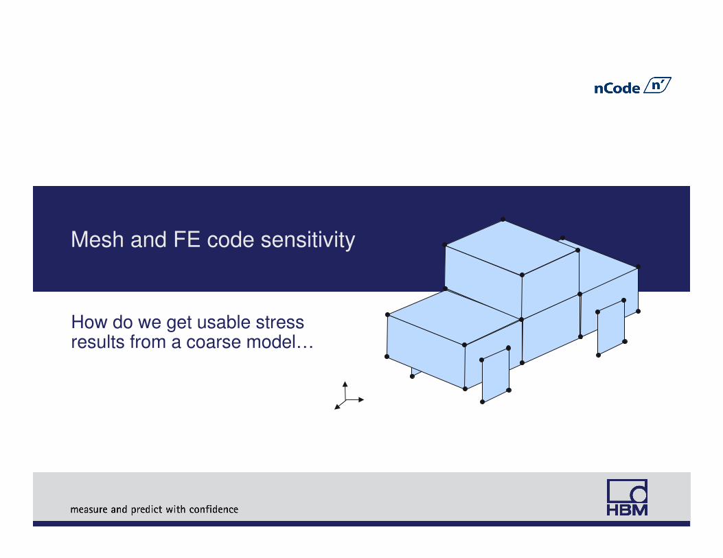
Mesh and FE code sensitivity
How do we get usable stressresults from a coarse model…
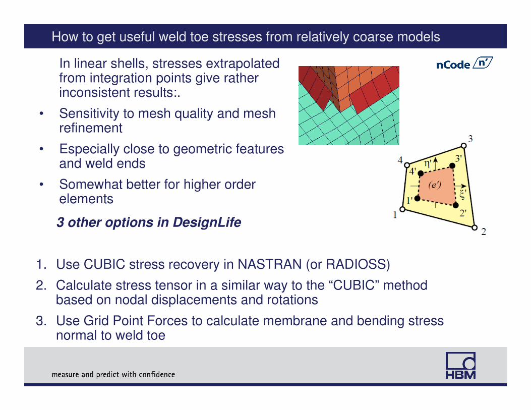
How to get useful weld toe stresses from relatively coarse models
3 other options in DesignLife
1. Use CUBIC stress recovery in NASTRAN (or RADIOSS)
2. Calculate stress tensor in a similar way to the “CUBIC” method based on nodal displacements and rotations
3. Use Grid Point Forces to calculate membrane and bending stress normal to weld toe
In linear shells, stresses extrapolated from integration points give rather inconsistent results:.
• Sensitivity to mesh quality and mesh refinement
• Especially close to geometric features and weld ends
• Somewhat better for higher order elements
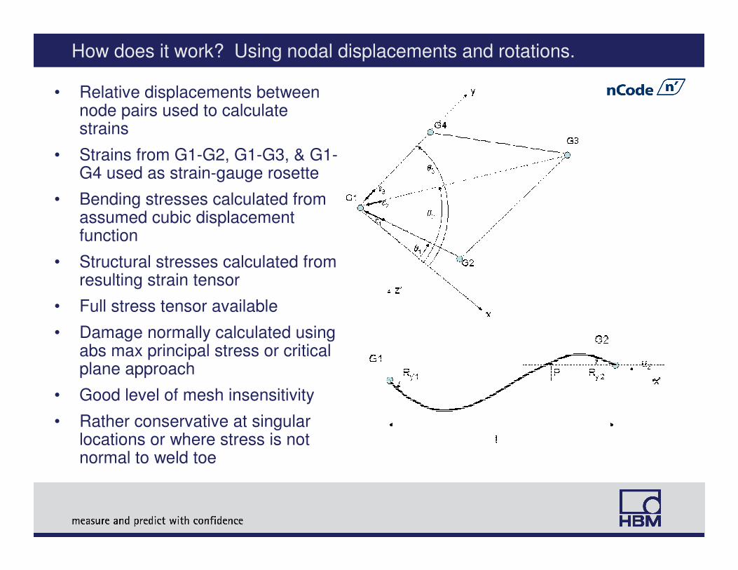
How does it work? Using nodal displacements and rotations.
• Relative displacements between node pairs used to calculate strains
• Strains from G1-G2, G1-G3, & G1-G4 used as strain-gauge rosette
• Bending stresses calculated from assumed cubic displacement function
• Structural stresses calculated from resulting strain tensor
• Full stress tensor available
• Damage normally calculated using abs max principal stress or critical plane approach
• Good level of mesh insensitivity
• Rather conservative at singular locations or where stress is not normal to weld toe
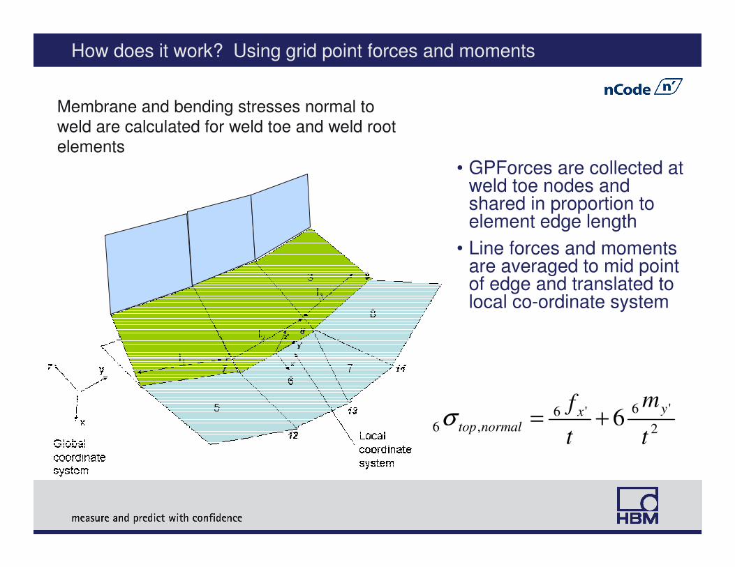
How does it work? Using grid point forces and moments
Membrane and bending stresses normal to
weld are calculated for weld toe and weld root
elements
2
'6'6
,66
t
m
t
f yxnormaltop +=σ
• GPForces are collected at weld toe nodes and shared in proportion to element edge length
• Line forces and moments are averaged to mid point of edge and translated to local co-ordinate system
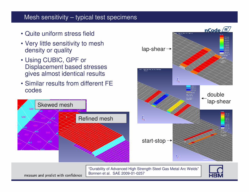
Mesh sensitivity – typical test specimens
• Quite uniform stress field
• Very little sensitivity to mesh density or quality
• Using CUBIC, GPF or Displacement based stresses gives almost identical results
• Similar results from different FE codes
lap-shear
double
lap-shear
start-stop
Skewed mesh
Refined mesh
“Durability of Advanced High Strength Steel Gas Metal Arc Welds”
Bonnen et al. SAE 2009-01-0257
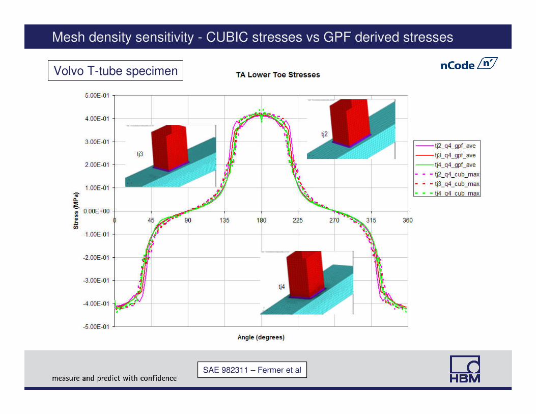
Mesh density sensitivity - CUBIC stresses vs GPF derived stresses
Volvo T-tube specimen
SAE 982311 – Fermer et al
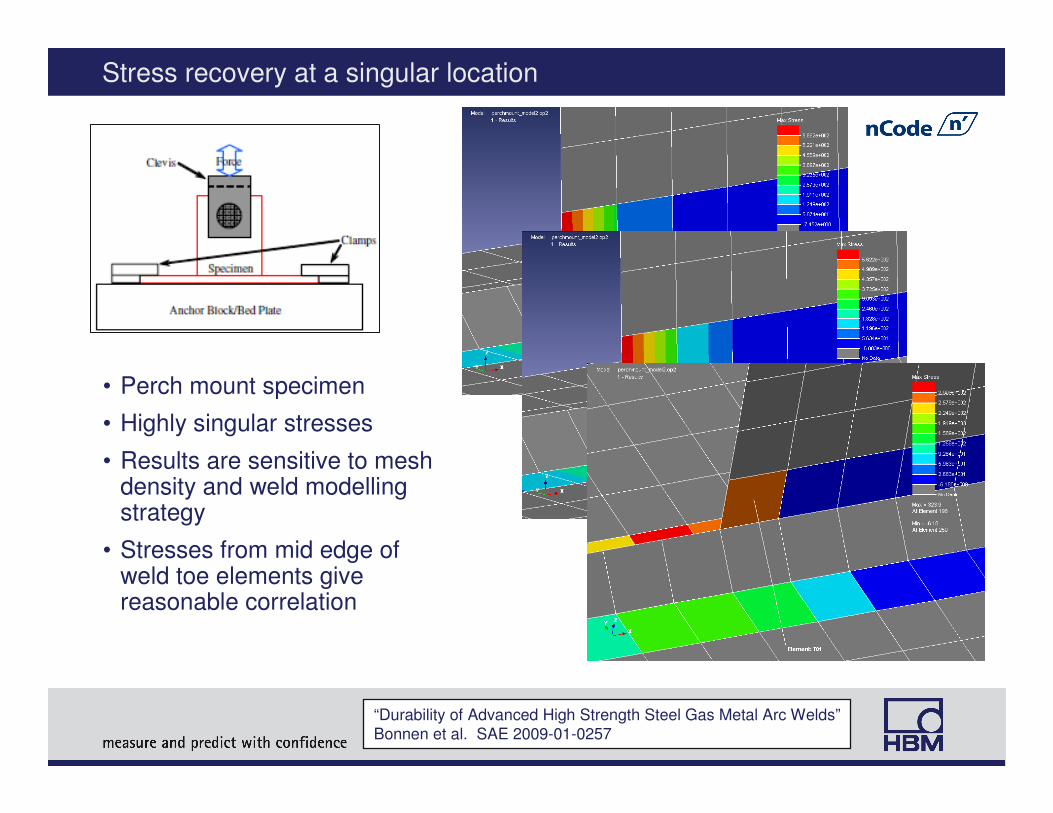
Stress recovery at a singular location
• Perch mount specimen
• Highly singular stresses
• Results are sensitive to mesh density and weld modelling strategy
• Stresses from mid edge of weld toe elements give reasonable correlation
“Durability of Advanced High Strength Steel Gas Metal Arc Welds”
Bonnen et al. SAE 2009-01-0257
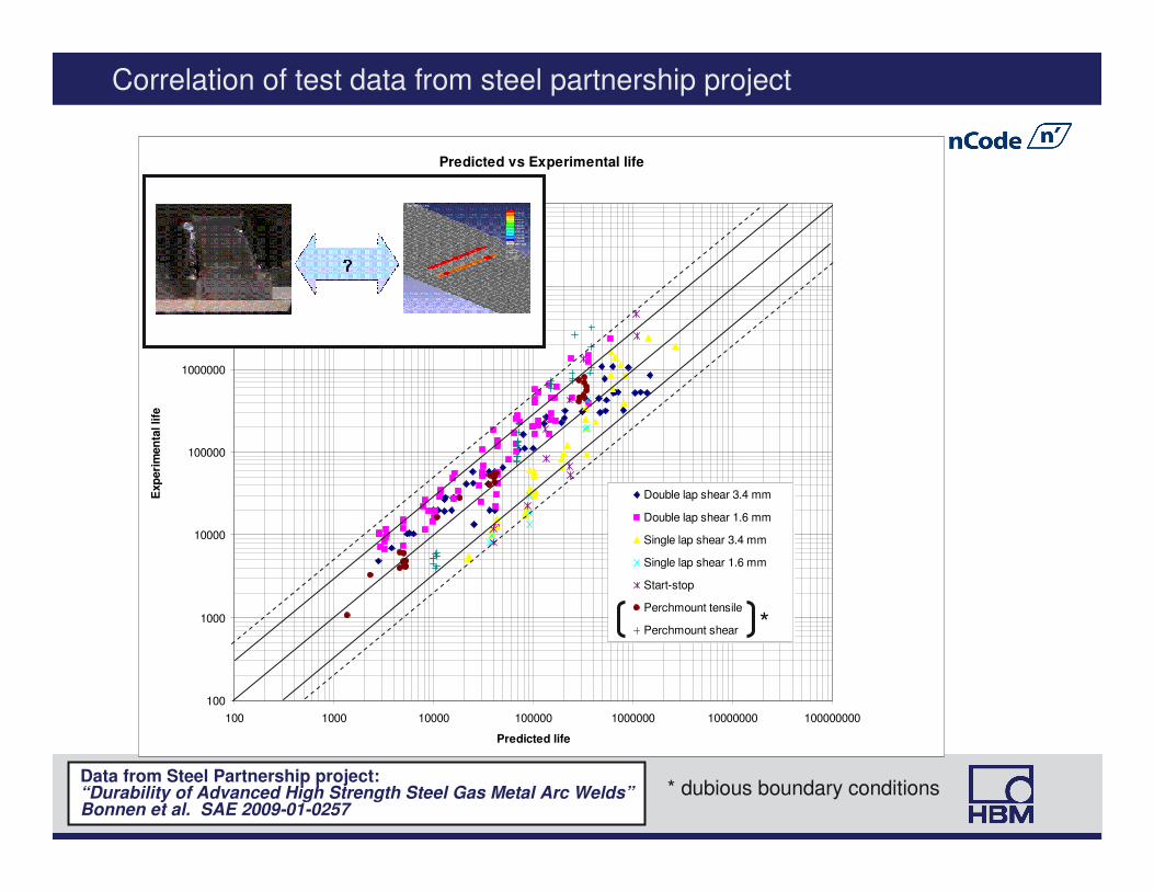
Correlation of test data from steel partnership project
Predicted vs Experimental life
100
1000
10000
100000
1000000
10000000
100000000
100 1000 10000 100000 1000000 10000000 100000000
Predicted life
Exp
eri
men
tal life
Double lap shear 3.4 mm
Double lap shear 1.6 mm
Single lap shear 3.4 mm
Single lap shear 1.6 mm
Start-stop
Perchmount tensile
Perchmount shear *
* dubious boundary conditionsData from Steel Partnership project:“Durability of Advanced High Strength Steel Gas Metal Arc Welds”Bonnen et al. SAE 2009-01-0257
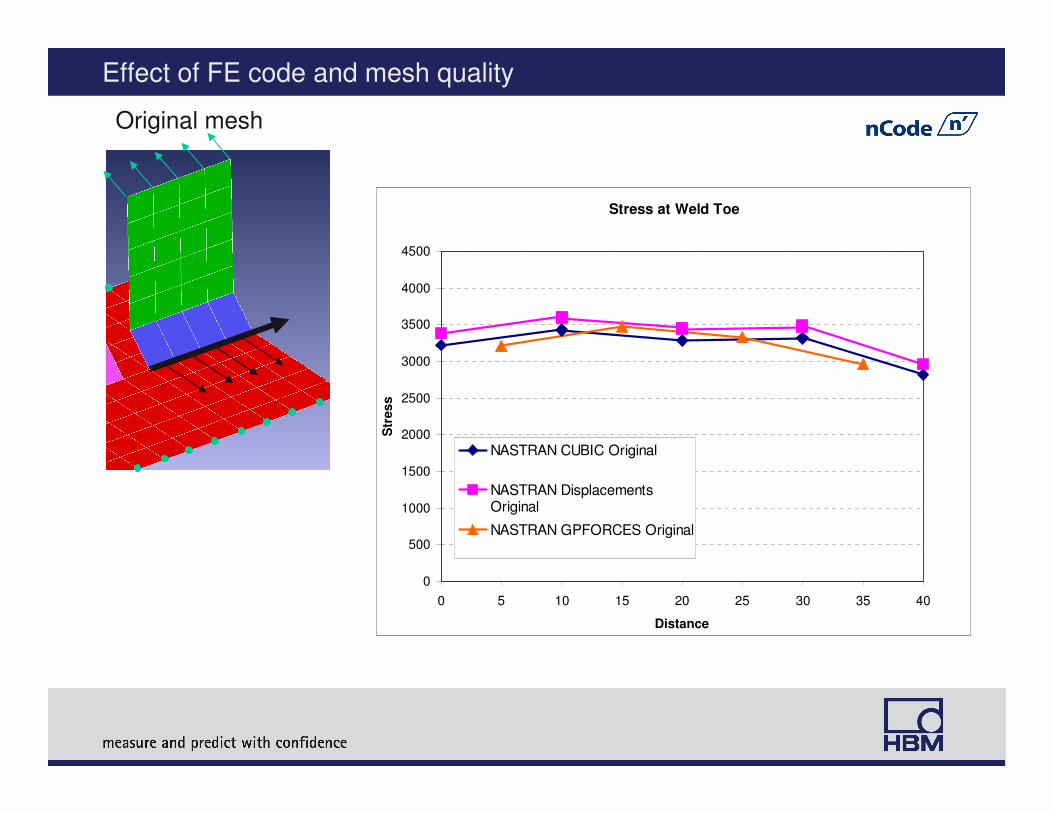
Effect of FE code and mesh quality
Original mesh
Stress at Weld Toe
0
500
1000
1500
2000
2500
3000
3500
4000
4500
0 5 10 15 20 25 30 35 40
Distance
Str
es
s
NASTRAN CUBIC Original
NASTRAN DisplacementsOriginal
NASTRAN GPFORCES Original
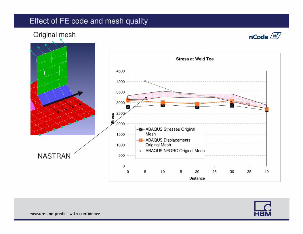
Effect of FE code and mesh quality
Original mesh
Stress at Weld Toe
0
500
1000
1500
2000
2500
3000
3500
4000
4500
0 5 10 15 20 25 30 35 40
Distance
Str
es
s
ABAQUS Stresses OriginalMesh
ABAQUS DisplacementsOriginal Mesh
ABAQUS NFORC Original Mesh
NASTRAN
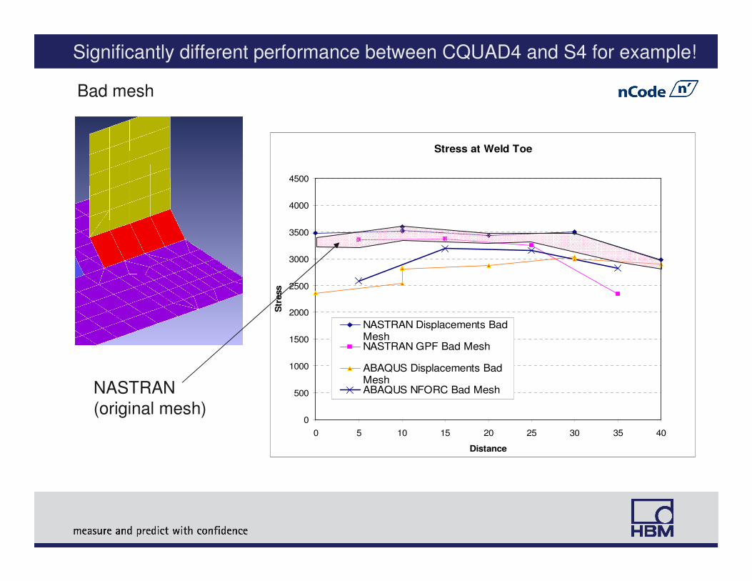
Significantly different performance between CQUAD4 and S4 for example!
Bad mesh
Stress at Weld Toe
0
500
1000
1500
2000
2500
3000
3500
4000
4500
0 5 10 15 20 25 30 35 40
Distance
Str
ess
NASTRAN Displacements BadMeshNASTRAN GPF Bad Mesh
ABAQUS Displacements BadMeshABAQUS NFORC Bad MeshNASTRAN
(original mesh)
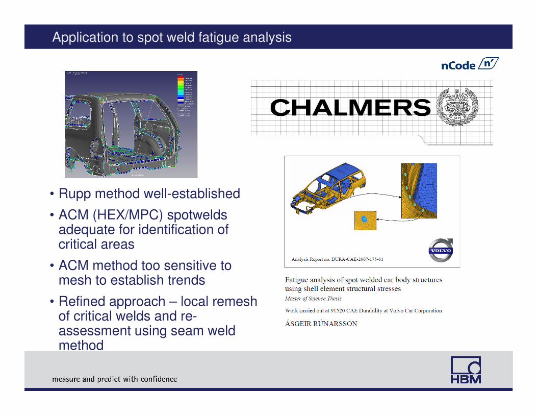
Application to spot weld fatigue analysis
• Rupp method well-established
• ACM (HEX/MPC) spotweldsadequate for identification of critical areas
• ACM method too sensitive to mesh to establish trends
• Refined approach – local remeshof critical welds and re-assessment using seam weld method

Refined analysis of spotwelds using “seam weld” method
• Most damaged ACMs automatically replaced by “spider”
• Additional shell elements inserted to permit recognition as seam welds
• Stable predictions permit reliable evaluation of design alternatives
Test – 501 repeats Prediction – 600 repeats
Concluding remarks
• DesignLife is readily configurable to predict fatigue life of welds using a variety of methods, including well-known standards
• The “Volvo” method implemented in DesignLife provides an effective, highly configurable, cost-effective and easy to use solution for seamweld fatigue life prediction in welded sheet structures
• All FE results are mesh sensitive, but mesh sensitivity can be minimised by:
4Sensible application of modelling guidelines
4Using appropriate stress recovery methods (CUBIC, displacements, GPF)
4Averaging and translating stresses to mid point of element edges
• Not all linear quad elements are the same! In what are rather non-converged meshes, results may differ using different FE codes