Tunnelling & underground design (Topic5-hard & weak rock tunnelling)

FASTCASTTM CONCRETE SOLUTIONS
Tunnelling and underground products
COMMUNICATIONS TRANSPORT WATER UTILITIES
> Delivering
pp
g,
An AMEC company

2 Bucline Shaft Linings
6 Bucline Caisson Shaft Linings
10 Caisson Shaft Units
13 Shaft Cover and Landing Slabs
16 Buclock Tunnel Linings
18 Six Segment Trapezoidal Tunnel Linings
22 Buclock
26 Standard Bolted Linings
30 Jacking Pipes
PROMISEThe BuchanCHANGES IN THE WAY WE LIVE AND WORK HAVE CREATED AN INCREASING DEMAND FOR MORE MODERN METHODS OF CONSTRUCTION.
At Buchan, we promise to deliver more efficient, cost effective and safety-focused sustainable solutions.
Our vision is to exceed our customers’ expectations as the premier off-site concrete solutions provider.
FASTCASTTM Structures
FASTCASTTM Bathroom Pods
FASTCASTTM Terracing
FASTCASTTM Bridges & Gantries
FASTCASTTM Underground
UNDERGROUNDFASTCASTTM
FASTCAST UNDERGROUND FROM BUCHAN CONCRETE SOLUTIONS HAS BEEN DEVELOPED TO OFFER A COMPREHENSIVE RANGE OF SUPPORTING MATERIALS FOR USE IN BELOW-SURFACE CONSTRUCTION PROCESSES.
FASTCAST Underground aims to provide customers with a safe, precast product that can be easily installed, with minimum finishing required, when working in an underground environment.
Buchan offers a bespoke service for specific tunnel and shaft projects, based on 40 years experience in supplying the tunnelling industry worldwide as well as providing proprietary standard products.
Contents:
Please view our website for our other FASTCAST solutions.

An AMEC companyTunnel and shaft linings 2
Bucline Shaft Linings
A Bucline shaft is a smooth segmental shaft joined together by hidden mechanical fixings. The strong connections bolt together segment to segment and ring to ring, complete with seals if required, to form a finished shaft lining. Our patented system retains all the benefits of strength, flexibility and speed of erection associated with a bolted ring, whilst at the same time, provides the client with a smooth finished shaft.
Range: 2.440m to 25.000m
Smoothbore, single pass shaft lining
Fast construction with minimum finishing required
Full range of ancilliary products
Bucline Shaft Linings
2

An AMEC companyTunnel and shaft linings 3
Materials Concrete The concrete mix design normally used provides for a characteristic strength of 50N/mm2 at 28 days.
All raw materials comply with current British and European standards.
Manufacturing is carried out in accordance with the requirements of our quality management system, audited by the British Standards Institute (BSI) to comply with BSEN ISO 9001:2000.
Caulking grooves and sealing grooves Segments are cast with caulking grooves on the internal circumferential and longitudinal sides. Rings also have grooves cast into the joint faces of each segment, for hydrophilic sealing strip.
Special rings can be supplied to meet the specific requirements of a contract or a sealing system.
Grout/Lifting sockets Each segment has one coarse threaded plastic lifting/grout socket complete with a threaded plastic grout plug.
Non return valves Plastic non return valves are provided.
Packings Bituminous felt packing 3mm nominal thickness are used on all longitudinal joints and will be supplied with the rings.
Building equipment Details of underpinning devices can be supplied on request.
Special rings Landing support is accomodated by standard sized rings with an integral corbel. Cutting edge and choker rings are available for many sizes to enable shaft sinking by caisson techniques.
Bucline Shaft Linings

An AMEC companyTunnel and shaft linings 4
Int. dia. Ext. dia. Depth Segments Volume Weight per Weight per per ring per ring ring segment metres metres metres Ord Top Key m3 tonnes kg 2.44 2.74 0.75 3 2 1 0.915 2.24 450 2.74 3.05 0.75 3 2 1 1.057 2.58 520 3.05 3.35 0.75 4 2 1 1.131 2.77 455 3.35 3.65 0.75 4 2 1 1.237 3.03 505 3.66 3.96 0.75 4 2 1 1.347 3.30 550 4.00 4.30 0.75 5 2 1 1.467 3.59 515 4.50 4.80 0.75 6 2 1 1.643 4.03 505 5.00 5.35 1.00 6 2 1 2.845 6.97 870 5.50 5.90 1.00 6 2 1 3.581 8.77 1100 6.00 6.45 1.00 7 2 1 4.400 10.78 1200 6.50 6.95 1.00 7 2 1 4.754 11.65 1300 7.00 7.45 1.00 8 2 1 5.107 12.51 1250 7.50 7.95 1.00 8 2 1 5.460 13.37 1340 9.00 9.50 1.00 12 2 1 7.265 17.80 1270 10.30 10.90 1.00 14 2 1 9.990 24.48 1530 10.67 11.27 1.00 14 2 1 10.339 25.33 1585 12.50 13.15 1.00 14 2 - 13.095 32.80 2050 15.00 15.75 1.00 16 2 1 18.113 44.50 2500 19.00 20.00 1.00 22 2 1 30.631 75.00 3100 20.00 21.00 1.00 18 2 - 32.201 78.89 3950 25.00 26.00 1.00 28 2 1 40.055 98.135 3270
Bucline Shaft LiningsTypical segment layout
����������
Caulkinggroove
Double-eyebolt
Section showingdouble-eyebolt fixing
Bucsealgroove
Construction by under-pinning
Bituminous packing to all longitudinal joints
Plastic grout/lifting socket
Bucline shaft details

An AMEC companyTunnel and shaft linings 5
Bucline Shaft Linings
Shaft constructed as a caisson
Heavy duty cover slab
Choker ring
Cutting edge
Standard 'Bucline' shaftsavailable with:-
Bolt pockets incutting edge & chokerfor ease of building
Corbel ring
Intermediate landing slab
Standard 'Bucline'shaft ring
Sealants:-
Caulking (standard)Hydrophilic strip (optional)
Grout hole:-
Threaded plastic socket complete with plug and NRV.
Heavy duty cover slabCorbel ringIntermediate landing slabChoker ringCutting edge‘Panelled’ rings forshear-key purposes

An AMEC companyTunnel and shaft linings 6
Bucline Caisson Shaft Linings
A Bucline Caisson shaft is a smooth segmental shaft joined together by external fixings. The strong connections bolt together segment to segment and ring to ring, complete with gaskets, to form a finished shaft lining. Our system retains all the benefits of strength, flexibility and speed of erection associated with a bolted ring, whilst providing the client with a safer system of working, by reducing man-entry into the shaft and working at height.
Range: 6.000m to 15.000m
Smoothbore, single pass shaft lining
Fast construction with minimum finishing required
Full range of ancilliary products
Bucline C
aisson Shaft LiningsNEW
6

An AMEC companyTunnel and shaft linings 7
Materials Concrete The concrete mix design normally used provides for a characteristic strength of 50N/mm2 at 28 days.
All raw materials comply with current British and European standards.
Manufacturing is carried out in accordance with the requirements of our quality management system, audited by the British Standards Institute (BSI) to comply with BSEN ISO 9001:2000.
Caulking grooves and sealing grooves Segments are cast with caulking grooves on the internal circumferential and longitudinal sides. Rings also have grooves cast into the joint faces of each segment, for EPDM Gaskets. Special rings can be supplied to meet the specific requirements of a contract or a sealing system.
Grout sockets Each segment has one coarse threaded plastic grout socket complete with a threaded plastic grout plug.
Non return valves Plastic non return valves are provided.
Packings Bituminous felt packing 3mm nominal thickness are used on all longitudinal joints and will be supplied with the rings.
Special rings Landing support is accomodated by standard sized rings with an integral corbel. Combined cutting edge and choker rings are available for many sizes.
Bucline Caisson Shaft Linings

An AMEC companyTunnel and shaft linings 8
Int. dia. Ext. dia. Depth Segments Volume Weight per Weight per per ring per ring ring segment Metres Metres Metres Ord Top m3 tonnes kg 6.00 6.45 1.00 7 2 4.400 10.78 1200
6.50 6.95 1.00 7 2 4.754 11.65 1300
7.00 7.45 1.00 8 2 5.107 12.51 1250 7.50 7.95 1.00 8 2 5.460 13.37 1340 9.00 9.50 1.00 12 2 7.265 17.80 1270 10.30 10.90 1.00 14 2 9.990 24.48 1530 12.50 13.15 1.00 14 2 13.095 32.80 2050 15.00 15.75 1.00 16 2 18.113 44.50 2500
Bucline Caisson Shaft LiningsTypical joint arrangement
Hexagonal coupler
WasherGrummet
M16 Tie rod
Fixing
Joint Detail
Coupler
Washer andgrummet
Gasket
Tie rod
Caulkinggroove
Typical cross joint detail
Caulking groove
Radiused bolt
Gasketgroove
Caisson shaft details

An AMEC companyTunnel and shaft linings 9
Bucline Caisson Shaft Linings
Shaft constructed as a caisson
Heavy duty cover slab
Combined cutting edgeand choker ring withpanelled inner surfacefor shear key
Standard 'Bucline Caisson'shafts available with:-
Choker for easeof building
Corbel ring
Intermediatelanding slab
Standard 'BuclineCaisson’ shaft ring
Sealants:-
Caulking (standard)EPDM gasket (standard)
Grout hole:-
Threaded plastic socket complete with plug and NRV.
Heavy duty cover slabCorbel ringIntermediate landing slabCombined cutting edgeand choker ring‘Panelled’ rings forshear-key purposes
Radiusedbolt holes

An AMEC companyTunnel and shaft linings 10
Caisson Shaft Units
Range: 2.550m to 3.000m
Full range of ancilliary products
Buchan Concrete Solutions produce a range of standard one piece caisson units suitable for fast and simple construction of small diameter shafts.
They bolt together vertically, complete with seals, to form a finished shaft lining.
Special designs are also available.
Caisson Shaft U
nits
10

An AMEC companyTunnel and shaft linings 11
MaterialsAll raw materials comply with current British and European standards.
Manufacturing is carried out in accordance with the requirements of our quality management system, audited by the British Standards Institute (BSI) to comply with BSEN ISO 9001:2000.
Seals The flexible joint seals are manufactured from uncured butyl rubber which meets the requirements of the 'Civil Engineering Specification for the Water Industry'.
Caulking grooves All units are cast with a caulking groove on the bottom of the internal circumferencial joint.
Grout holes and plugs Caisson units are supplied with coarse thread plastic sockets and plugs with sealing washers.Plastic non-return valves are provided.
Lifting Caisson units are supplied with three threaded lifting sockets.Caissons must be lifted using an appropriate three leg chain and M20 lifting loops. The angle of the chain with the horizontal must be no less than 45 degrees.Lifting loops are available on request. Cover slabs are supplied with strand lifting loops. Slabs must be lifted using suitably balanced chains and shackles with a minimum 40mm diameter pin through all the strand lifting loops and provided with a minimum chain angle of 60 degrees between slab and chain.
Special unitsCaisson UnitsUnits can be manufactured to suit alternative specifications for a particular contract.
Cutting edge Steel cutting edges can be supplied as an alternative.
Platform supports and landing slabs Galvanised mild steel open mesh landing slabs and angle supports can be supplied as an alternative to give a greater clearance during construction.
Caisson Shaft Units
Hexagonal coupler
WasherGrummet
M16 Tie rod
FixingStandard unit
Joint detailCaulking groove
Coupler
Washer and grummet
sealant strip
Tie rod
Bolt holes
Coarse threaded plastic grout sockets
Lifting inserts
Sealant groove and caulking groove on underside
Nominal Internal External Weight of units No. of tie rods dia. dia. dia. 1.0m 0.5m and couplers mm mm mm Tonne Tonne M16 2550 2590 2890 3.2 1.6 5 2700 2740 3040 3.3 1.7 5 3000 3050 3350 3.7 1.8 6

An AMEC companyTunnel and shaft linings 12
Caisson Shaft Units
Cover slab
Combined concrete cutting edgeand choker ring
Steel cutting shoe (optional)supplied ready, fitted tostandard ring
Cover slabCombined cutting edge and choker ring
Standard caisson unit
Sealants:-Butyl rubber
Grout hole:-Threaded plasticsocket with plug and NRV

An AMEC companyTunnel and shaft linings 13
Range: 1.520m to 15.000m
Normal reinforced concrete design
Made to order, fast availability on standard designs
Buchan Concrete Solutions produce a range of sectional cover slabs and internal landings.
Special designs also available to accommodate crane capacity constraints.
Shaft Cover and Landing Slabs

An AMEC companyTunnel and shaft linings 14
Shaft Cover and Landing SlabsDesign Slabs are manufactured to your requirements, designed in line with the recommendations of B.S. 8110: Part 1.
i) Intermediate slabs are designed to carry an imposed load of 5kN/m2.
ii) Heavy duty cover slabs are designed to carry 45 units of H.B. wheel loading as defined in B.S. 5400: Part 2, together with up to 4m depth of fill.
It is not recommended that slabs be placed less than 0.6m below the road surface.
Cover to reinforcement complies with B.S. 8110, Table 3.4 - Severe exposure.The concrete mix design normally used provides for a characteristic strength of 50N/mm2 at 28 days, when cubes are cured and tested in accordance with B.S. 1881.The standard range of cover slabs includes one access opening of 900mm square or diameter. Special slabs can be designed to meet non standard loading or access hole layouts.Installation Units should be laid on a flat level sand/cement mortar bed, minimum thickness 15mm.
Joints on the top surface and the vertical joints on the end of the units are provided with rebates which should be pointed with sand/cement mortar or sealed with an appropriate jointing or caulking compound, depending upon the site conditions.
Joint details Unless otherwise indicated on the drawing, all joints between units are construction joints and are not designed to transmit load.
Construction joints should be sealed using 40 x 25 Tokstrip (or similar approved), placed centrally on the step prior to the placing of units.
Openingadjacent toshaft wall
Min 15mm sand/cement mortar bed
15mm undersize on radius
60¡min
or
Var
ies
Lifting details Slab units are supplied with four strand lifting loops. Slabs must be lifted using suitable balanced chains and shackles with a minimum 40mm diameter pin through all the strand lifting loops provided, with a minimum chain angle of 60 degrees between slab and chain.
Var
ies
Sealant
Rebate
3
20
50
Shaft Cover and Landing Slabs
14

An AMEC companyTunnel and shaft linings 15
Heavy duty cover slabs
Int. dia. ring Ext. dia. slab Thickness No. of units Max. piece wt. Total wt. metres metres mm tonnes tonnes 2.13 2.40 225 1 2.13 2.13 2.44 2.71 225 1 2.84 2.84 2.74 3.02 275 2 2.85 4.46 3.05 3.32 275 2 3.32 5.50 3.35 3.62 325 2 4.18 7.86 3.66 3.93 325 2 5.03 9.39 4.00 4.27 375 2 6.85 12.92 4.50 4.77 425 2 9.68 18.49 5.00 5.32 450 2 12.75 24.58 5.50 5.87 450 3 10.35 30.12 6.00 6.42 500 4 13.76 40.24 6.50 6.92 500 4 11.99 46.92 7.00 7.42 500 4 13.78 54.10 7.50 7.92 500 5 12.56 61.78 9.00 9.47 600 8 14.00 107.00 10.67 11.24 650 12 14.00 164.00Note: Sizes may vary to suit individual customers requirements.
Int. dia. ring Ext. dia. slab Thickness Half slab wt. Half slab Full slab Full slab metres metres mm tonnes* No. of Units Total wt. No. of units 2.13 2.08 150 0.62 1 0.95 1 2.44 2.39 150 0.82 1 1.35 1 2.74 2.69 175 1.22 1 2.09 1 3.05 3.00 200 1.73 1 3.07 2 3.35 3.30 200 2.10 1 3.79 2 3.66 3.61 225 2.82 1 5.20 2 4.00 3.95 225 3.38 1 6.31 2 4.50 4.45 250 4.76 1 9.03 2 5.00 4.95 250 5.89 1 11.29 2 5.50 5.45 300 8.57 1 16.54 2 6.00 5.95 350 11.92 2 23.15 3 6.50 6.45 400 16.01 2 31.23 3 7.00 6.95 400 18.59 2 36.38 3 7.50 7.45 400 21.36 2 41.93 4 9.00 8.95 500 41.00 3 80.00 6 10.67 10.62 550 63.00 5 124.00 10
Intermediate slabs
Note: Sizes may vary to suit individual customers requirements. *No opening in standard half slab.
Shaft Cover and Landing Slabs

An AMEC companyTunnel and shaft linings 16
Range: 1.200m to 2.440m
Smoothbore single pass tunnel lining
Fast construction with minimum finishing
Patented connections
A Buclock tunnel is a completely smooth segmental tunnel lining joined together by hidden mechanical fixings. This range of linings has been developed to provide accurate construction with conventional tunnelling shields. The patented system of connections provides a lining that is strong, flexible and fast to build, whilst providing a smooth finished tunnel.
Buclock Tunnel Linings
Buclock Tunnel Linings
16

An AMEC companyTunnel and shaft linings 17
Buclock Tunnel Linings
Dimensions Segments Vol. Wt. Wt. per ring per ring per ring per seg. Int. dia. Ext. dia. Width metres metres Metres I O T K m3 tonnes kg 1.20 1.42 0.61 1 4 - - 0.274 0.67 140 1.52 1.77 0.61 1 2 2 1 0.394 0.95 190 1.68 1.93 0.61 1 2 2 1 0.432 1.04 208 1.83 2.08 0.61 1 2 2 1 0.468 1.12 225 1.96 2.21 0.61 1 2 2 1 0.500 1.20 240 2.13 2.43 0.61 1 2 2 1 0.655 1.57 315 2.44 2.74 0.61 1 2 2 1 0.745 1.79 357
Smoothbore linings for larger sizes are provided with other connections, please contact our Technical Department for details.Note: Buchan have a policy of continuous product development and reserve the right to change the specification without prior notice.
Exploded view looking towards face
Bituminous Packing
Location Pins
Quick Thread Bolts
Plastic Locking Couplers
Grout Holes
Materials Concrete The concrete mix design normally used provides for a characteristic strength of 50N/mm2 at 28 days.All raw materials comply with current British and European standards.Manufacturing is carried out in accordance with the requirements of our quality management system, audited by the British Standards Institute (BSI) to comply with BSEN ISO 9001:2000.
Manufacture Caulking grooves and sealing grooves All segments are cast with caulking grooves and sealing grooves to suit Bucseal hydrophilic strip on the circumferential and longitudinal sides.Grout/Lifting holes and plugs Each segment has one 50mm nominal diameter coarse threaded plastic lifting/grout socket, complete with threaded plastic grout plugs to facilitate fast and safe machine erection. Non return valves are provided.

An AMEC companyTunnel and shaft linings 18
Six Segment Trapezoidal Tunnel Linings
Range: 2.070m to 3.840m
Smoothbore, single pass construction
Tapered lining for curved and straight driving
Avoids a cruciform joint between segments
Developed in conjunction with leading consultants and contractors, these single pass smoothbore linings have been designed for use with closed face tunnelling machines.
The linings can be designed to accommodate elastomeric compression gaskets or hydrophilic seals. Individual segments are wedge shaped thus eliminating the need for a special closure segment.
Six Segment Trapezoidal Tunnel Linings
18

An AMEC companyTunnel and shaft linings 19
Design The six segment smoothbore rings incorporate the latest in lining technology and have been designed to accommodate the increasing demands from modern Tunnel Boring Machines (TBMs) and bad ground conditions. Segments are designed to be machine handled with a rotating arm erector and are provided with an innovative and fast coarse thread plastic socket at the centroid for lifting and grouting.
A thicker smoothbore ring section has been designed to cater for larger shield ram shove forces and to incorporate elastomeric gaskets.
The patented Buclock connection is incorporated on the circumferential joints in place of the bolted connection: Combining the advantages of a solid dowel and a secure threaded connection, it is fast and easy to build and eliminates pockets on the circle joints.
The rings have been used in some of the worst tunnelling conditions in the United Kingdom with very high external water pressures. A major advantage of this design is the reduced incidence of cruciform joints (where the corners of four segments meet). This has always proved an area prone to water ingress in previous designs with gaskets. Even when rings are built with the same orientation, a full segment in the invert, the cruciform joint is avoided completely.
The trapezoidal joint arrangement also assists a good ring build and helps maintain the ring shape prior to grouting. With this type of ring the last segment erected is always in the top half of the bore.
Materials All raw materials comply with current British and European standards. Manufacturing is carried out in accordance with the requirements of our quality management system, audited by the British Standards Institute (BSI) to comply with BSEN ISO 9001:2000.
Caulking grooves and Sealing grooves All segments are cast with caulking grooves on the circumferential and longitudinal sides. Sealing grooves for either hydrophilic strip or elastomeric compression gaskets can be incorporated at the time of casting.
Grout/Lifting sockets Each segment has one coarse threaded plastic lifting/grout socket and threaded plastic grout plug with sealing washer. Plastic non return valves are provided.
Grummets Standard segments are normally cast with shaped bolt hole recesses designed to accommodate gel impregnated grummets: these grummets can be supplied if required.
Packings Bituminous felt packings of 3mm nominal thickness should be used on all longitudinal joints and can be supplied if required.
Circumferential packings Circumferential packings made from 3mm bituminous felt or 3mm or 6mm timber can be supplied if required.
Special rings The rings currently available have a taper across one axis as detailed in the table opposite. Non standard tapers can be manufactured to the purchaser’s specific requirements.
Buclock Connectors Buclock connectors are resistant to microbiological attack and are suitable for use with potable water.
Six Segment Trapezoidal Tunnel Linings

An AMEC companyTunnel and shaft linings 20
Internal dia. External dia. Max. ring Min. ring Wt. per Ring Bolts per ring* width width segment wt. Metres Metres mm mm kg tonnes No. x dia. x length (mm) 2.07 2.43 1010 990 520 3.10 12 x M16 x 295 2.44 2.80 1007 993 600 3.60 12 x M16 x 355 2.85 3.21 1007.5 992.5 700 4.19 12 x M16 x 365 2.90 3.26 1005 995 710 4.27 12 x M16 x 365 3.35 3.71 1010 1000 820 4.89 12 x M16 x 400 3.38 3.84 1083 1051 1200 6.80 12 x M20 x 490 3.84 4.24 1015 985 1040 6.20 12 x M20 x 410
30o
Internal diameter
External diameter
60o 30 o
30 o60 o
15o
1000 (Nom
inal)
1 No Plastic grout/Lifting socket
Elevation on ring
Inner face of typical segment Typical cross joint detail
Sealing groove
Caulking groove
Radiused bolt
12 no. equally spaced
Bituminous packing to all longitudinal joints
Typical circle joint detail
Buclock connectors
Ring details
Standard ring dimensions
* All bolts have a 300m radius except the 3.38 I.D. ring - 340m radiusThe bolt lengths listed above serve only as a guide and clients should satisfy themselves that they are sufficient for their purposes.Note:- Buchan have a policy of continuous product development and reserve the right to change the specification without prior notice.
Six Segment Trapezoidal Tunnel Linings

An AMEC companyTunnel and shaft linings 21
Fig 1. The rings consist of three different segment types. Segments are supplied to the erector in a predetermined sequence dependant upon the alignment required. The ring orientation is altered by erecting segments in a different order.
Fig 2. The staggered joint pattern, avoiding the cruciform joint (where the edges of four corners meet) is a major feature.
Bolt pockets and caulking grooves are caulked or pointed to provide the finished lining.
Fig 3. The plastic grout/lifting socket has a specially developed coarse thread for tunnel and shaft linings which allows easy thread starting and fast fixing. Plastic non-return valve, threaded grout plug and sealing washer are also available.
Fig 1.
Fig 2.
Fig 3.
Non-return valve
Plastic grout/lifting socket
Sealing washer
Threaded grout plug
Non-re
turn v
alve
Plastic
grou
t/
lifting
sock
et
Sealin
g was
her
Thre
aded
grou
t plug
Sealin
g was
her
Thre
aded
grou
t plug
Non-re
turn v
alve
Plastic
grou
t/
lifting
sock
et
Rings in same orientationfor curved alignment
Rings rotated at 120o for straight alignment
Six Segment Trapezoidal Tunnel Linings

An AMEC companyTunnel and shaft linings 22
BuclockPlastic tunnel lining connection
Patented high strength connection
Reduced erection and finishing time
Available for use by clients designer or manufacturer
Combining the advantages of a solid dowel and a secure threaded connection, this patented self-locking plastic connector provides a superb circle joint fixing for tunnel linings. Suitable for use with packings, hydrophilic seals and EPDM compression gaskets, it is fast and easy to build and has no pockets/recesses to fill.
Buclock - Plastic Tunnel Lining C
onnection
22

An AMEC companyTunnel and shaft linings 23
BuclockPlastic tunnel lining connection
High strength dowelgiving self alignmentand good shearconnection
Threaded screwconnection whichallows a push fit
Movable plasticanchors allow segmentto be located whenimperfectly aligned
Shield ram thrust
Design The Buclock circle joint connection has been developed over many years to provide the ideal connection between tunnel rings. Manufactured from a high strength durable plastic it combines the advantages of a bolted connection with the speed, economy and alignment characteristics of a dowel.
The system has been developed in conjunction with major tunnelling contractors and is suitable for use in traditional open face shields or with the latest full face tunnel boring machines. The dowels allow a very fast ring erection sequence and are designed to reduce lipping between segments.
The secure interlocking system is tolerant of a dirty environment and allows for the initial misalignment of segments to compensate for tapered joints and gaskets, thus it is suitable for use with all types of tunnel rings and, in particular, with the trapezoidal segment rings. It has been used in some of the worst soft ground tunnelling conditions in the U.K.
Major advantages Highly durable connection with no corrodible parts
Fast ring construction sequence
Minimum building clearance (50mm standard, 75mm heavy duty) allows the use with most types of tunnelling machine and ram length
The rigid dowel action of the coupler re-aligns the segment and minimises the stepping of joints
Self-locking
Self-aligning
No extra reinforcement required
Suitable for trapezoidal segment rings
Simple and easy to use
Does not induce bursting forces in the concrete
No circle joint pockets to fill
Suitable for use with all types of sealing system, including EPDM compression gaskets and hydrophilic seals.

An AMEC companyTunnel and shaft linings 24
BuclockPlastic tunnel lining connection
0 0.5 1 1.5 2 2.5 3 3.5 4 4.5 50
0.5
1
1.5
2
2.5
3
3.5
4
Load
(t)
Extension (mm)
Heavy Duty
Standard
0 2 4 6 8 10 12 14 16 18 200
2
4
6
8
10
12
Load
(t)
Deflection (mm)
Heavy Duty
Standard
Test results for Buclock fixingsAssembly load
Tensile strength
Shear strength
Average load required to achieve joint closure (without gasket) Standard = 8KN, Heavy duty = 11KN.
Shear strength at failure Standard > 6 tonnes, Heavy duty > 10 tonnes.
The graph opposite shows typical test results from shear tests carried out with Buclock fixings cast into concrete test pieces.
Tensile strength at failure, Standard > 1.25 tonnes, Heavy duty > 3.0 tonnes.
The graph opposite shows typical test results from tensile tests carried out with Buclock fixings cast into concrete test pieces.

An AMEC companyTunnel and shaft linings 25
BuclockPlastic tunnel lining connection
Compatability with gasketsBuclock is fully compatible with elastic compression
gaskets. The elastic performance of the connection
compliments the compression characteristic of the
gaskets, which means that it can be used with a stiff
gasket and copes with varying joint gaps.
The graph below shows the compression curve for a
stiff EPDM compression gasket with a compression
force to closure of 25kN/m2, superimposed on the
extension characteristic of the heavy duty Buclock
connection when used with a 2.44m I.D. tunnel lining.
Gasket compression
Water pressure
Joint gap
Buclockextension
00
2.5
5
7.5
10
12.5
15
17.5
20
22.5
25
0.5 1 1.5 2 2.5 3 3.5 4 4.5 5
Load
(kN
)
Joint gap (mm)
A resultant joint gap of 1.5mm @ equillibrium. Gasket sealing performance remains unaffected
Stiff EPDM gasket compression characteristic
Heavy duty Buclock extension characteristic
Buclock/gasket interaction
25

An AMEC companyTunnel and shaft linings 26
Standard Bolted Linings
Range: 1.520m to 25.000m
Economical and simple to build
Full range of ancilliary products
Buchan Concrete Solutions produce a standard range of high quality concrete bolted segments for all types of tunnels.
All standard bolted rings can be used for the construction of tunnels, shafts and manholes.
Segments can also be designed to suit individual circumstances.
A full range of cutting edges, choker rings, platform support rings and cover slabs are available to assist in shaft construction.
Standard Bolted Linings
26

An AMEC companyTunnel and shaft linings 27
Standard Bolted Linings
Materials Concrete The concrete mix design normally used provides for a characteristic strength of 50N/mm2 at 28 days.
All raw materials comply with current British and European standards.
Manufacturing is carried out in accordance with the requirements of our quality management system, audited by the British Standards Institute (BSI) to comply with BSEN ISO 9001:2000.
Caulking grooves and sealing grooves All segments are cast with caulking grooves on the internal circumferential and longitudinal sides. Rings also have grooves cast into the joint faces of each segment for hydrophilic sealing strip.
Special rings can be supplied to meet the specific requirements of a contract or a sealing system.
Grout holes and plugs Each segment has one coarse threaded plastic socket and plug. Non return valves are provided.
Grummets All standard segments are cast with shaped bolt hole recesses, designed to accommodate gel impregnated grummets; these grummets can be supplied if requested.
Packings Bituminous felt packing, 3mm nominal thickness, should be used on all longitudinal joints and can be supplied if requested.Circumferential packings Circumferential packings made from 3mm thick bituminous felt or 3mm, 6mm or 10mm timber can be supplied, if required, to correct for line and level or for large radius curves. Special Rings Tapered rings Precast concrete tapered rings or precast concrete tapered packings can be manufactured to purchaser's specific requirements.
Landing support Standard rings with an integral corbel are available.
Cutting edges/Choker rings Cutting edges and choker rings are available for many sizes to enable shafts to be constructed by the caisson technique.

An AMEC companyTunnel and shaft linings 28
Standard Bolted LiningsStandard bolted concrete segmental rings
Dimensions Segments Volume Weight Max. Bolts per Ring*
per per per Piece Cross & Circle Key Int. dia. Ext. dia. Width ring ring ring Wt. No. dia. x length No. dia. x length
Metres Metres mm O T Key m3 tonnes tonnes mm mm
1.52 1.77 610 3 2 1 0.292 0.70 0.139 18 M20 x 165 2 M20 x 255
1.68 1.93 610 3 2 1 0.333 0.80 0.159 23 M20 x 165 2 M20 x 255
1.83 2.08 610 3 2 1 0.355 0.85 0.169 23 M20 x 165 2 M20 x 255
2.13 2.43 610 3 2 1 0.460 1.10 0.219 23 M20 x 180 2 M20 x 265
2.44 2.74 610 3 2 1 0.490 1.18 0.238 23 M20 x 180 2 M20 x 265
2.74 3.05 610 4 2 1 0.566 1.36 0.230 28 M20 x 180 2 M20 x 265
3.05 3.35 610 4 2 1 0.622 1.49 0.247 28 M20 x 180 2 M20 x 265
3.35 3.65 610 4 2 1 0.701 1.68 0.279 34 M20 x 180 2 M20 x 265
3.66 3.96 610 4 2 1 0.749 1.80 0.298 34 M20 x 180 2 M20 x 265
3.96 4.27 610 5 2 1 0.847 2.03 0.292 40 M20 x 180 2 M20 x 265
4.27 4.57 610 6 2 1 0.901 2.16 0.272 38 M20 x 215 2 M20 x 315
4.57 4.93 610 7 2 1 1.243 2.98 0.328 43 M24 x 230 2 M24 x 330
5.28 5.71 610 8 2 1 1.569 3.77 0.377 48 M24 x 230 2 M24 x 330
6.10 6.63 610 10 2 1 2.436 5.85 0.487 58 M24 x 250 2 M24 x 350
7.62 8.28 610 13 2 1 3.597 8.63 0.576 73 M24 x 250 2 M24 x 350
9.25 10.10 610 16 2 1 6.032 14.48 0.804 88 M27 x 270 2 M27 x 370
10.65 11.51 610 18 2 1 6.797 16.31 0.813 98 M27 x 270 2 M27 x 370
15.00 15.90 1000 16 2 15.419 37.01 2.06 90 M30 x 420 - NO KEY
19.00 20.00 1000 22 2 1 22.580 54.19 2.300 118 M30 x 420 4 M30 x 210
25.00 26.00 1000 28 2 1 29.125 69.90 2.330 148 M30 x 420 4 M30 x 210
*Bolt lengths allow for two standard washers and gel grummets and 3mm thick packings between joints. All bolts have 100mm thread length. The bolt lengths listed above serve only as a guide and clients should satisfy themselves that they are sufficient for their requirements. Some ring dimensions are approximate as a result of conversion from imperial to metric dimensions.
NOTE: Buchan have a policy of continuous product development and reserve the right to change the specification without prior notice.

An AMEC companyTunnel and shaft linings 29
Shaft constructed as a caisson
Heavy duty cover slab
Choker ring
Cutting edge
Standard bolted shaftsavailable with:-
Heavy duty cover slabCorbel ring or platform support ringIntermediate landing slabChoker ringCutting edge
Corbel ring(corbel at ring centreon small diameter)
Intermediatelanding slab
Standard shaft ring
Standard shaft ring
Grout hole
Sealants:-
Caulking Hydrophilic rubber strip(optional)
Grout hole:-
Coarse threaded plasticwith plug and NRV
Standard Bolted Linings

An AMEC companyTunnel and shaft linings 30
Range: 1.200m to 2.400m
Special pipes can be designed to individual
requirements
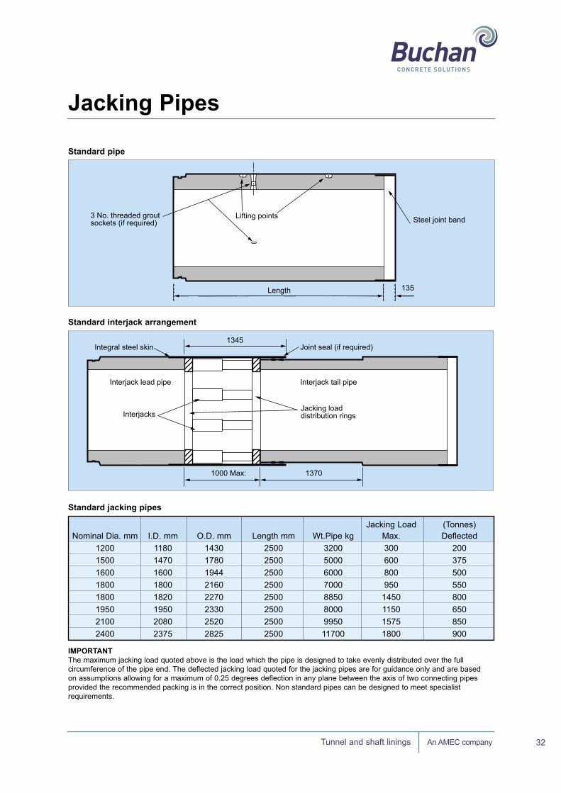
Buchan Concrete Solutions produce a comprehensive range of standard jacking pipes to suit the requirements of the latest generation of pipe jacking systems. The pipes incorporate the well proven butt joint with integral steel band. This joint design ensures that the jacking forces are transmitted over the maximum area of the pipe, thus reducing the possibility of damage due to jacking loads.
Jacking Pipes
Jacking Pipes
30

An AMEC companyTunnel and shaft linings 31
MaterialsAll raw materials comply with current British and European standards.
Manufacturing is carried out in accordance with the requirements of our quality management system, audited by the British Standards Institute (BSI) to comply with BSEN ISO 9001:2000.
Joint bands The joint bands are manufactured from mild steel.Stainless steel may be provided at extra cost.
Seals The flexible joint seals are manufactured from natural rubber, or E.P.D.M.
Compressible packings A compressible packing is to be positioned between every pipe to ensure even distribution of the jacking load. The recommended packing is an 18mm thick 650/675kg/m3 density chipboard firmly anchored in position.
Bentonite injection holes Pipes can be supplied with or without threaded screwed sockets and plugs. These are cast in to meet the purchasers specific requirements.
Special pipesInterjack station pipes A standard range of specially developed Interjack station pipes are available and can be designed to meet the requirements of the majority of contracts.
Shield pipes (Lead pipes) These pipes can be produced to suit the requirements of the contractor's shield and excavation method.Corrosion resistant pipes All pipes are available with various corrosion resistant finishes. These finishes are cast into the pipes at manufacture and form an integral part of the pipe.
The corrosion resistant finishes are available on either the external or internal surfaces of the pipe and include full joint details, thus providing a pipeline resistant to chemical attack from ground water or effluent.
Jacking Pipes
Standard Joint Detail Standard Joint Detail
Secondary seal(if required)
Captive rubberseal
Minimum 25mm
Minimum 25mm
Steel joint band18mm Compressible packing
An AMEC companyTunnel and shaft linings 32
Jacking Pipes
Length 135
Steel joint band3 No. threaded grout sockets (if required)
Lifting points
Integral steel skin
Interjack lead pipe Interjack tail pipe
InterjacksJacking loaddistribution rings
Joint seal (if required)1345
1000 Max: 1370
Standard Interjack Arrangement
Standard PipeStandard pipe
Length 135
Steel joint band3 No. threaded grout sockets (if required)
Lifting points
Integral steel skin
Interjack lead pipe Interjack tail pipe
InterjacksJacking loaddistribution rings
Joint seal (if required)1345
1000 Max: 1370
Standard Interjack Arrangement
Standard Pipe
Standard interjack arrangement
Jacking Load (Tonnes) Nominal Dia. mm I.D. mm O.D. mm Length mm Wt.Pipe kg Max. Deflected 1200 1180 1430 2500 3200 300 200 1500 1470 1780 2500 5000 600 375 1600 1600 1944 2500 6000 800 500 1800 1800 2160 2500 7000 950 550 1800 1820 2270 2500 8850 1450 800 1950 1950 2330 2500 8000 1150 650 2100 2080 2520 2500 9950 1575 850 2400 2375 2825 2500 11700 1800 900
Standard jacking pipes
IMPORTANTThe maximum jacking load quoted above is the load which the pipe is designed to take evenly distributed over the full circumference of the pipe end. The deflected jacking load quoted for the jacking pipes are for guidance only and are based on assumptions allowing for a maximum of 0.25 degrees deflection in any plane between the axis of two connecting pipes provided the recommended packing is in the correct position. Non standard pipes can be designed to meet specialist requirements.

An AMEC companyTunnel and shaft linings 33
Jacking Pipes
Fig 1. Technical advice on pipe performance is available from our technical department.
Fig 2. The rubber seal is designed to be located in a pre-formed groove at the spigot end of the pipe, in order to provide a watertight joint.
Fig 3. Pipes can be designed to suit individual customer requirements. These 2,100mm diameter pipes used at the MEPAS contract in Liverpool were produced with 50mm cover to reinforcement.
Fig 4. Superb quality is achieved. The pipes are vertically cast to ensure a completely homogeneous structure for the wall and are reinforced with an all welded spiral double cage.
Joint rotation v Jacking loadM
axim
um ja
ckin
g lo
ad (T
onne
s)
1100
0 0.1 0.2 0.3 0.4 0.5Deflection (o)
0.6 0.7 0.8 0.9 1
1000
900
800
700
600
500
400
300
200
100
0
Joint deflection v Jacking load (typical)
Fig 2.
Fig 1.
Fig 3.
Fig 4.

How
DIRECTIONS FROM THE NORTH AND SOUTH
Exit M6 at junction 18. Follow A54 towards Middlewich for approximately 2 miles. At the first roundabout(Salt Cellar pub on left) turn right sign posted Northwich/Knutsford for approximately 200 yards. Take the first right sign posted Kutsford/Byley (B5081).
Follow road for approximately 2.7 miles passing Byley village crossroads, lookfor Stublach Dog Kennels on the lefthand side, turn immediately right into Kings Lane and Buchan is approximately 200 yards on the right.
TO FIND US
Cor
pora
te G
raph
ic D
esig
n, U
K. B
roch
/176
0 O
ctob
er 2
005
Buchan Concrete Solutions King’s Lane Byley Middlewich Cheshire CW10 9NBT: +44 (0) 1606 843500 F: +44 (0) 1606 842214 www.buchanconcrete.com