FastCAM Drawing Editor Video Tutorial
23
1 FastCAM Drawing Editor Video Tutorial Contents 1. Select Drawing Units ........................................................................................................................... 2 1.1 Restore a drawing ......................................................................................................................... 2 1.2 Select DXF File Units...................................................................................................................... 3 1.3 Verify Part ..................................................................................................................................... 3 2. Identify and Measure .......................................................................................................................... 5 2.1 Zoom Window ............................................................................................................................... 5 2.2 Autoscale....................................................................................................................................... 5 2.3 Verify Contours ............................................................................................................................. 6 2.4 Display parts and holes ................................................................................................................. 7 2.5 Add Dimension .............................................................................................................................. 8 2.6 Print part with a template............................................................................................................. 9 2.7 Save the drawing......................................................................................................................... 10 3. Extract a part .................................................................................................................................... 12 3.1 Extract a single part .................................................................................................................... 12 3.2 Extract multiple parts.................................................................................................................. 13 4. Erase Tools ........................................................................................................................................ 15 4.1 Deleting lines............................................................................................................................... 15 4.2 Deleting arcs ............................................................................................................................... 15 4.3 Erase Window ............................................................................................................................. 16 4.4 Erase text .................................................................................................................................... 17 5. How to change the Template............................................................................................................ 18 5.1 Set up drawing template............................................................................................................. 18 5.2 Use print template ...................................................................................................................... 19 6. Fix Broken Joints ............................................................................................................................... 21 6.1 Fixing single joints ....................................................................................................................... 21 6.2 Fix all joints.................................................................................................................................. 23
Transcript of FastCAM Drawing Editor Video Tutorial

1
FastCAM Drawing Editor Video Tutorial
Contents 1. Select Drawing Units ........................................................................................................................... 2
1.1 Restore a drawing ......................................................................................................................... 2
1.2 Select DXF File Units ...................................................................................................................... 3
1.3 Verify Part ..................................................................................................................................... 3
2. Identify and Measure .......................................................................................................................... 5
2.1 Zoom Window ............................................................................................................................... 5
2.2 Autoscale ....................................................................................................................................... 5
2.3 Verify Contours ............................................................................................................................. 6
2.4 Display parts and holes ................................................................................................................. 7
2.5 Add Dimension .............................................................................................................................. 8
2.6 Print part with a template............................................................................................................. 9
2.7 Save the drawing. ........................................................................................................................ 10
3. Extract a part .................................................................................................................................... 12
3.1 Extract a single part .................................................................................................................... 12
3.2 Extract multiple parts .................................................................................................................. 13
4. Erase Tools ........................................................................................................................................ 15
4.1 Deleting lines ............................................................................................................................... 15
4.2 Deleting arcs ............................................................................................................................... 15
4.3 Erase Window ............................................................................................................................. 16
4.4 Erase text .................................................................................................................................... 17
5. How to change the Template ............................................................................................................ 18
5.1 Set up drawing template ............................................................................................................. 18
5.2 Use print template ...................................................................................................................... 19
6. Fix Broken Joints ............................................................................................................................... 21
6.1 Fixing single joints ....................................................................................................................... 21
6.2 Fix all joints.................................................................................................................................. 23
2
1. Select Drawing Units
It is important to select the correct units when restoring a drawing.
As an example, if you have FastCAM set up in INCH units, any drawing that has been created
in INCH will import into FastCAM without any issues. If we want to import a drawing that is
in METRIC we are required to let FastCAM know during the import process.
This will ensure that FastCAM imports the drawing to the correct scale.
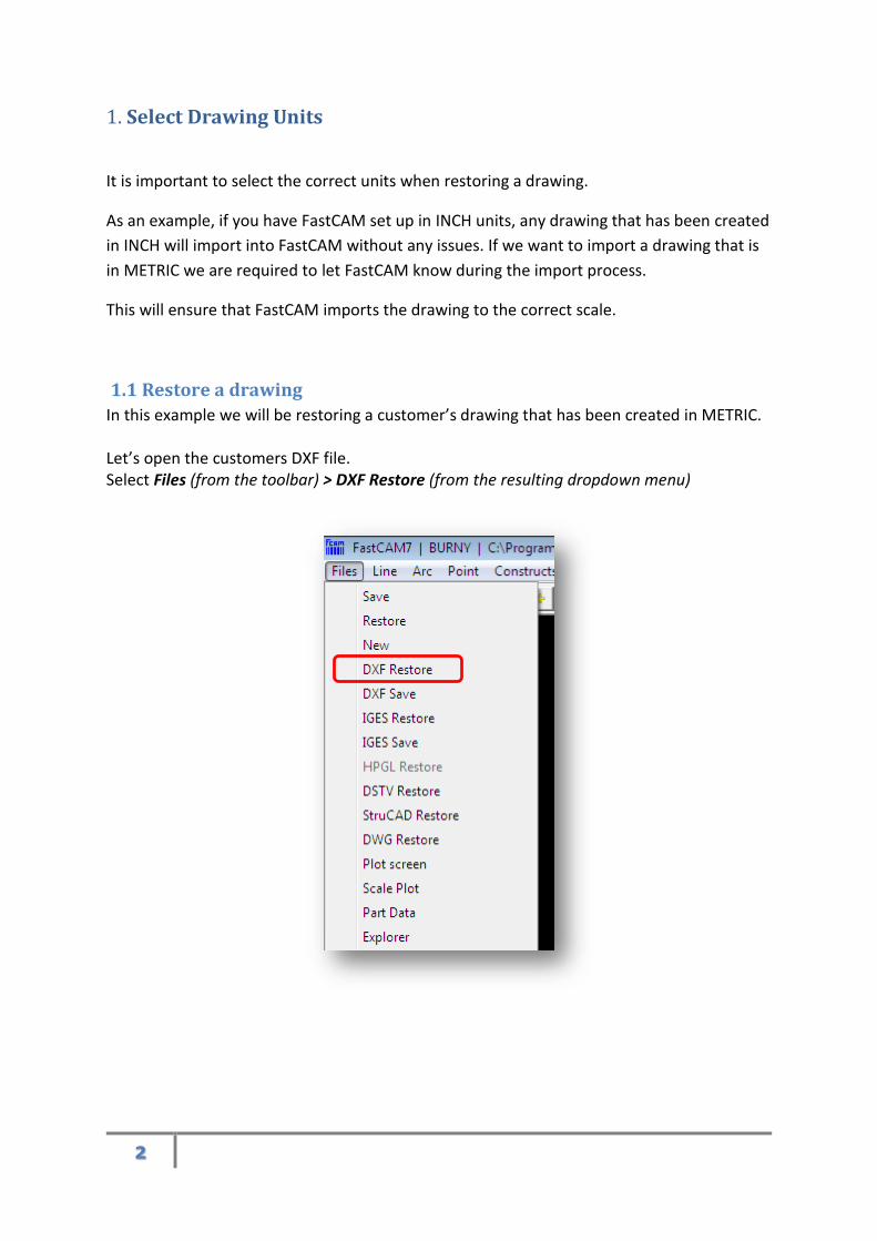
1.1 Restore a drawing
In this example we will be restoring a customer’s drawing that has been created in METRIC. Let’s open the customers DXF file. Select Files (from the toolbar) > DXF Restore (from the resulting dropdown menu)

3
1.2 Select DXF File Units
In our example we have chosen Metric units as the drawing is in Metric. FastCAM will
automatically convert the Metric Drawing into Imperial units.
1.3 Verify Part
Now we have our drawing loaded into FastCAM we need to verify it and check it using the
simple dimensioning tool.
Here is our PDF Drawing. Let’s check it in FastCAM

4
On the top toolbar click Verify>Add Dimension
1. Left click to select control point
2. Left click to select second control point
3. Left click to select position of dimension
4. Right click to exit add dimension mode.
1
3
2
5
2. Identify and Measure
First open the drawing using the DXF restore, as used in the earlier tutorial 1.1 Restore a
Drawing
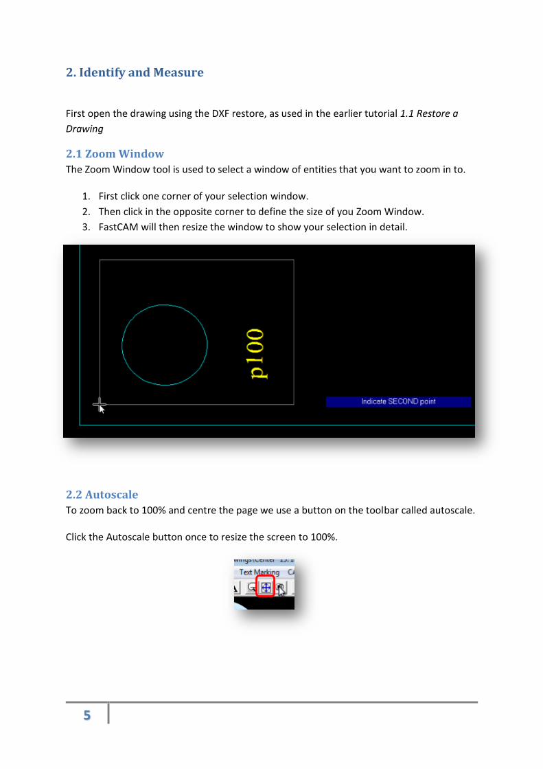
2.1 Zoom Window
The Zoom Window tool is used to select a window of entities that you want to zoom in to.
1. First click one corner of your selection window.
2. Then click in the opposite corner to define the size of you Zoom Window.
3. FastCAM will then resize the window to show your selection in detail.
2.2 Autoscale
To zoom back to 100% and centre the page we use a button on the toolbar called autoscale. Click the Autoscale button once to resize the screen to 100%.
6
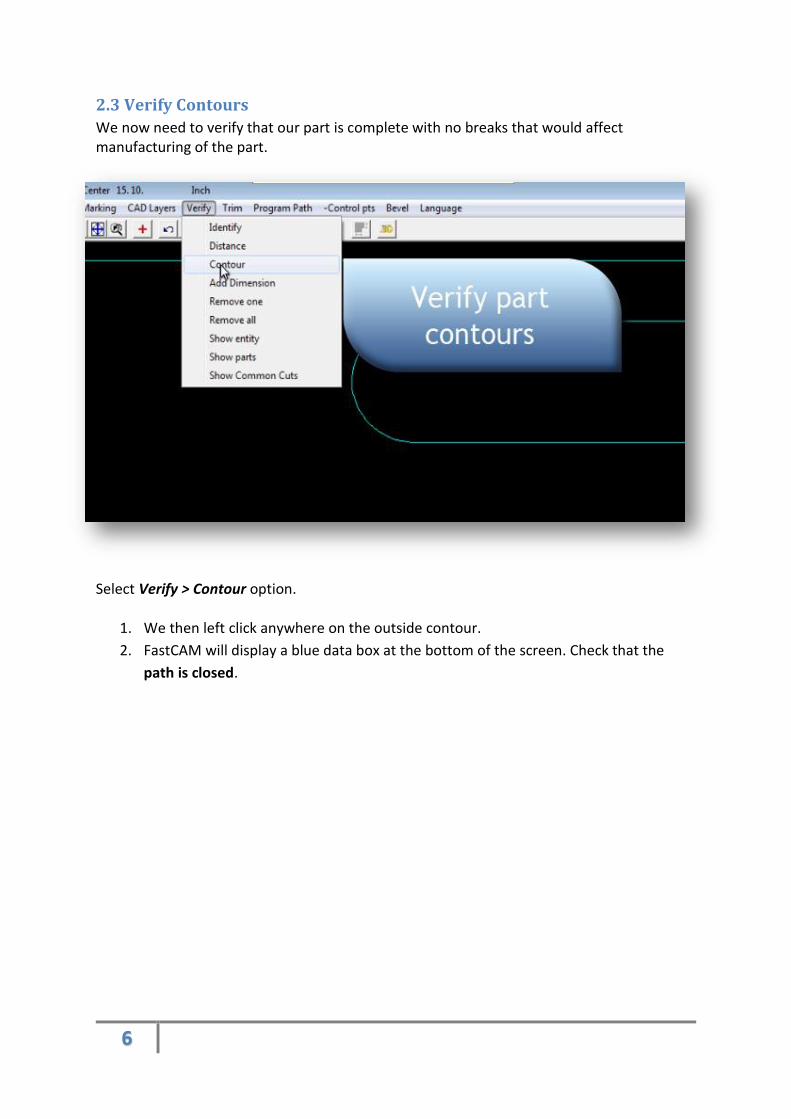
2.3 Verify Contours
We now need to verify that our part is complete with no breaks that would affect manufacturing of the part.
Select Verify > Contour option.
1. We then left click anywhere on the outside contour.
2. FastCAM will display a blue data box at the bottom of the screen. Check that the
path is closed.

7
3. If the path is open you will need to fix joints in order to close the path. (Fix joints is
covered in section 6 of this tutorial)
2.4 Display parts and holes
Once we have verified the part, we use a new tool to verify the parts inner and outer contours. The parts and holes tool will display the outside contour and then in a different colour, the internal contours. Find it by going to View > Parts and holes
8
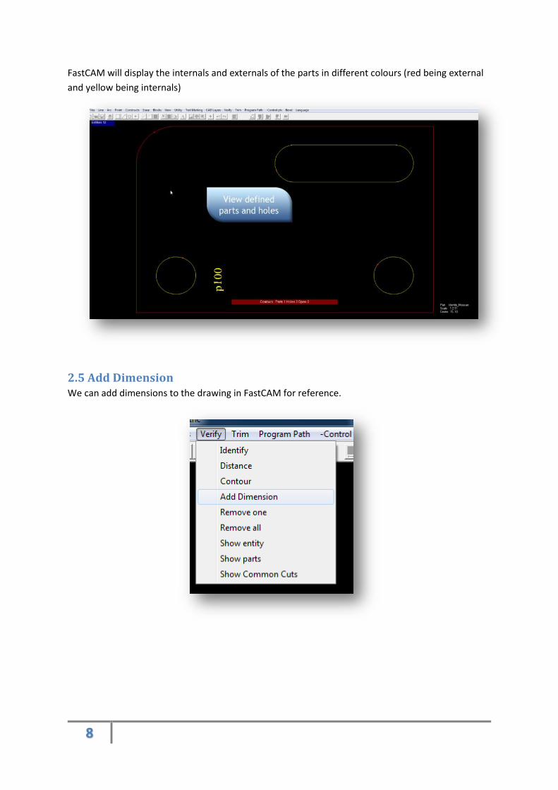
FastCAM will display the internals and externals of the parts in different colours (red being external
and yellow being internals)
2.5 Add Dimension We can add dimensions to the drawing in FastCAM for reference.

9
Using the Verify > Add Dimension option
2.6 Print part with a template. We will now show you printing with a template. (To change a template please see section 5 of this
tutorial)
To print the part, click the print icon on the toolbar.

10
You can choose many options for your print out, in our example we choose autoscale. This option
fits most requirements.
The FastCAM template can be modified to the customers’ preference. Please review your
FastCAM manual or contact your nearest FastCAM office for further support.
2.7 Save the drawing.
FastCAM can save the drawing as two main types.
1. FastCAM format CAM.
11
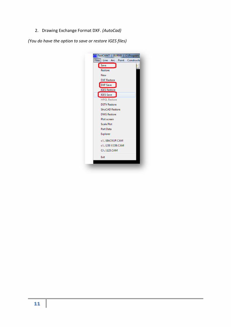
2. Drawing Exchange Format DXF. (AutoCad)
(You do have the option to save or restore IGES files)
12
3. Extract a part The extract part tool is used to extract a part or parts from a drawing that has many
parts/entities present.
In our example we open a DXF file that has many parts.
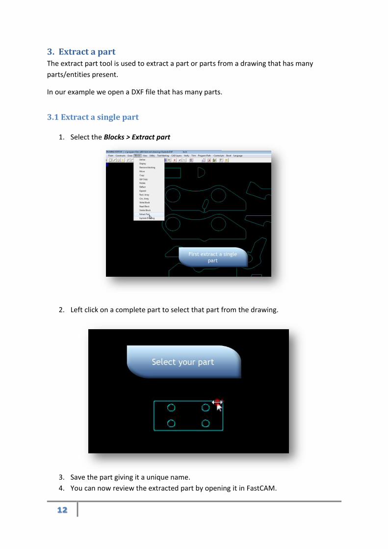
3.1 Extract a single part
1. Select the Blocks > Extract part
2. Left click on a complete part to select that part from the drawing.
3. Save the part giving it a unique name.
4. You can now review the extracted part by opening it in FastCAM.

13
3.2 Extract multiple parts
FastCAM can also extract all parts from the drawing.
1. Select the Blocks > Explode Drawing
2. Define the maximum gap in contour.
Maximum gap in contour refers to the individual parts. If a part has a break in the contour,
the defined value will instruct FastCAM to ignore breaks of that size.
Parts that are very close to each other are not affected by this defined value.
14
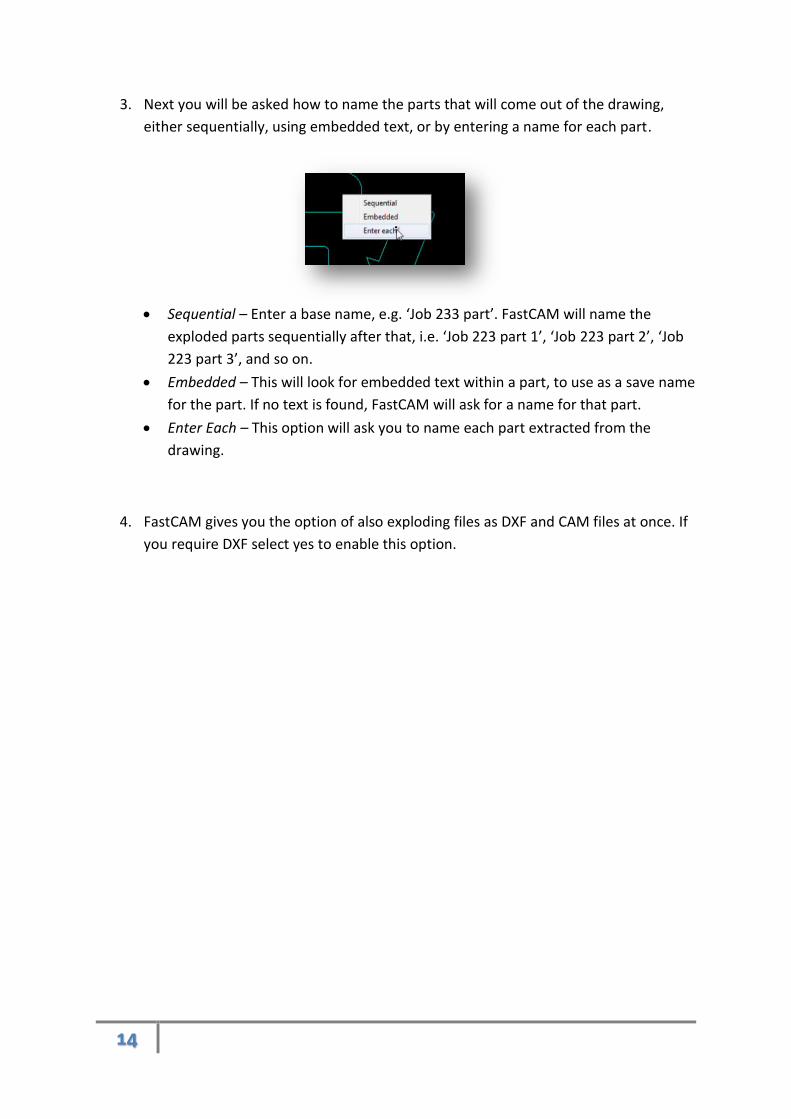
3. Next you will be asked how to name the parts that will come out of the drawing,
either sequentially, using embedded text, or by entering a name for each part.
Sequential – Enter a base name, e.g. ‘Job 233 part’. FastCAM will name the
exploded parts sequentially after that, i.e. ‘Job 223 part 1’, ‘Job 223 part 2’, ‘Job
223 part 3’, and so on.
Embedded – This will look for embedded text within a part, to use as a save name
for the part. If no text is found, FastCAM will ask for a name for that part.
Enter Each – This option will ask you to name each part extracted from the
drawing.
4. FastCAM gives you the option of also exploding files as DXF and CAM files at once. If
you require DXF select yes to enable this option.

15
4. Erase Tools FastCAM has many erase tools, several of the tools are entity specific. This enables the user
to quickly delete entities without deleting data that is needed.
4.1 Deleting lines
Select Erase > Line
Next click on the line entity that you want to be deleted. NOTE – using line erase you
cannot delete other types of entities such as arcs or text.
When you have your selected entities, right click to delete the selection.
4.2 Deleting arcs
Select Erase > Arc
As with the line delete tool, select your arc entities with a left click and confirm
deletion with a right click.
16
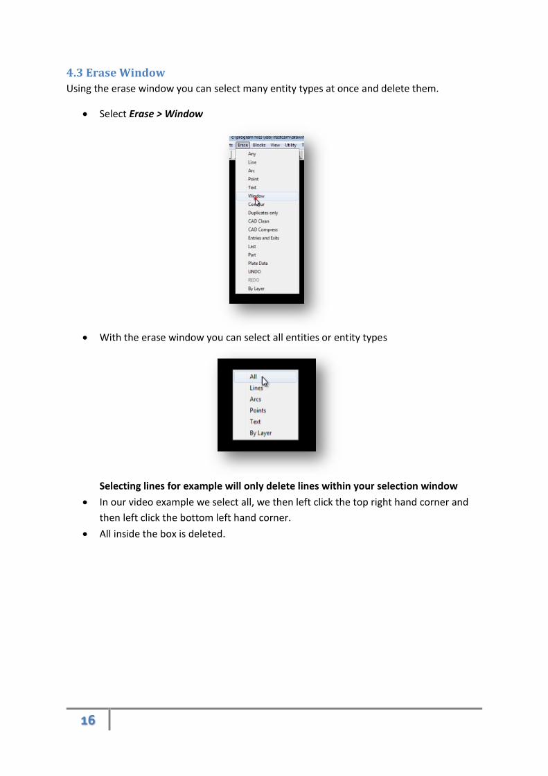
4.3 Erase Window
Using the erase window you can select many entity types at once and delete them.
Select Erase > Window
With the erase window you can select all entities or entity types
Selecting lines for example will only delete lines within your selection window
In our video example we select all, we then left click the top right hand corner and
then left click the bottom left hand corner.
All inside the box is deleted.
17
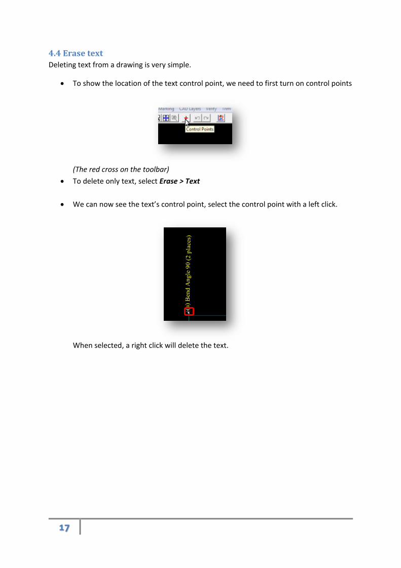
4.4 Erase text
Deleting text from a drawing is very simple.
To show the location of the text control point, we need to first turn on control points
(The red cross on the toolbar)
To delete only text, select Erase > Text
We can now see the text’s control point, select the control point with a left click.
When selected, a right click will delete the text.

18
5. How to change the Template FastCAM can display a drawing with or without a drawing template.
5.1 Set up drawing template
To turn on drawing templates select View -> Change Display.

19
Select Template from the plotter label section
Click inside the text box, and select the template from the pop-up window.
5.2 Use print template
Select the print icon from the toolbar

20
You can choose many options for your print out, in our example we choose
autoscale. This option fits most requirements.
The FastCAM template can be modified to the customers’ preference. Please review your
FastCAM manual or contact you nearest FastCAM office for further support.
21
6. Fix Broken Joints
Fixing broken joints is easy in FastCAM. You may come across a customer drawing where the
part contour is broken slightly. These tools are designed to make it easy for the user to fix
them with FastCAM.
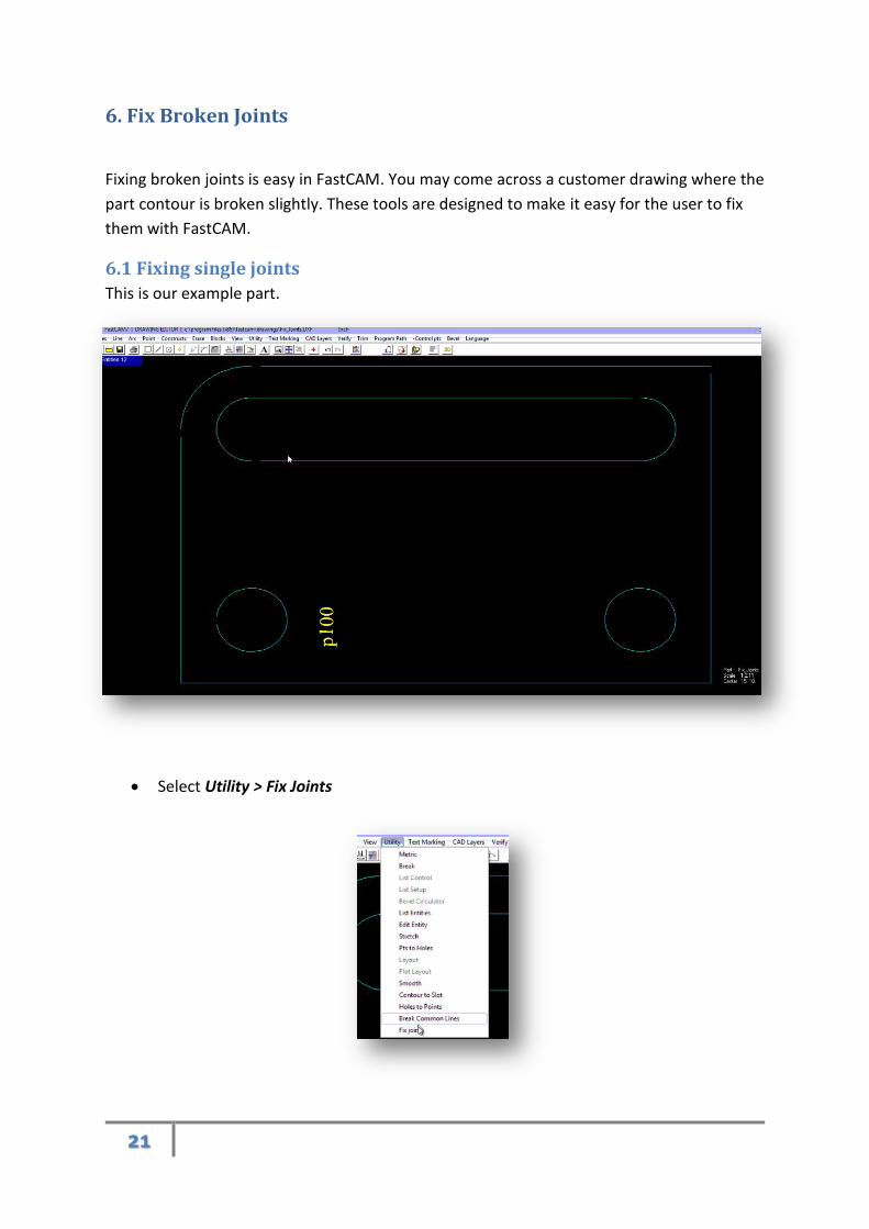
6.1 Fixing single joints
This is our example part.
Select Utility > Fix Joints

22
Select single joints
To fix a single joint simply left click on each entity either side of the break.
23
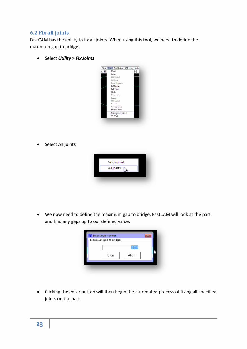
6.2 Fix all joints
FastCAM has the ability to fix all joints. When using this tool, we need to define the
maximum gap to bridge.
Select Utility > Fix Joints
Select All joints
We now need to define the maximum gap to bridge. FastCAM will look at the part
and find any gaps up to our defined value.
Clicking the enter button will then begin the automated process of fixing all specified
joints on the part.