
Fast Power Routing through HVDC - SPSpower.eng.usf.edu/docs/papers/2012PWRD_HVDC.pdf · Fast Power...
10
1 Fast Power Routing through HVDC Haiping Yin, Student Member, IEEE, Lingling Fan, Senior Member, IEEE, Zhixin Miao, Senior Member, IEEE Abstract—The objective of this paper is to investigate fast power routing capability of line current commutating (LCC)- HVDC. Such capability is most desired in future grids with high penetration of renewable energy sources (e.g., wind and solar). The technology presented in this paper replaces the traditional LCC-HVDC rectifier power order control by an ac voltage mode control. This technology enables the HVDC rectifier ac bus to act as an infinite bus and absorb fluctuating wind power. A study system consisting of an ac system, an LCC-HVDC, and a doubly-fed induction generator (DFIG) based wind farm is built in Matlab/SimPowersystems. Simulation studies are carried out to demonstrate the proposed HVDC rectifier control in routing fluctuating wind power and load change. Parameters of the proposed voltage mode control are investigated to show their impact on HVDC power routing and ac fault recovery. Index Terms—Doubly fed induction machine (DFIG), high- voltage direct current (HVDC), I. I NTRODUCTION F AST power routing capability is most desired for future grids with high penetration of renewable energy resources such as wind and solar. Due to their intermittent nature, power flow patterns in future grids will experience fluctuation more often. This poses challenges in system operation to manage congestion in a fast speed fashion. Flexible AC Transmission Systems (FACTS) and HVDC are two enabling technologies with fast power routing capabilities. HVDC has been an option to interconnect wind farms to ac grids [1]–[3]. There are currently voltage source converter (VSC)-based HVDC for mid-voltage level transmission [4] and LCC-HVDC for high- voltage level transmission [5]. The objective of this paper is to investigate the fast power routing capability of LCC-HVDC since LCC-HVDC is a ma- ture technology in high power high voltage transmission and have been used world wide. The term fast power routing refers to the capability of HVDC routing wind power fast enough to avoid local synchronous generators to pick up the power change. Traditionally, LCC-HVDC is equipped with current order control at its rectifier side [6]. The current reference is computed from the power order divided by the measured direct voltage. Therefore, power delivered through HVDC can be scheduled. This research aims to examine a new way to enable fast power routing by HVDC. Power scheduling does not suit for this aim since the power flow patterns keep changing and the power order should keep changing. Communication links are required to send the varying power order from wind farms to HVDC links. Additional computing time and communication time are needed. An HVDC is expected to This work was supported in part by the National Science Foundation under Grant ECCS 1005277. H. Yin, L. Fan and Z. Miao are with the Department of Electrical Engineering, University of South Florida, Tampa, FL 33620 (Emails: [email protected]; [email protected]; [email protected]). respond in a fast fashion. Therefore, an automatic control using local measurements is expected. The concept of infinite bus is implemented in designing such kind of automatic control. An infinite bus can absorb or gener- ate whatever power the rest of the system needed. To emulate an infinite bus, the ac bus at the rectifier side of an HVDC should be controlled to have a constant voltage. Therefore, a voltage mode control should replace the traditional power scheduling to realize fast power routing capability. Compared with the existing literature on HVDC and wind farm power coordination [7]–[9], the study scope is very different. This research investigates fast power routing for an area with combined conventional power plants and wind farms. The HVDC system is designed to route wind power to the grid from this area. Power routing control design for the HVDC system should coordinate the wind farm, the HVDC system and the conventional power plant. While in the existing literature, the purpose of an HVDC system is to deliver wind energy to the grid only. Coordination with the conventional generators is not considered. Also compared with the existing literature on HVDC and wind farm power coordination, the aforementioned approach has the following advantages: 1) The control does not rely on additional devices such as STATCOM. STATCOM converter are used for wind farms with HVDC delivery to provide reactive power [7], [10]–[12]. The dc-link voltage of a STATCOM reflects the power unbalance between wind farms and an HVDC link. Hence the dc-link voltage is used as a feedback signal to adjust the HVDC rectifier current order. In this paper, since a hybrid ac/dc system is the study objective, synchronous source is presented at the wind farm side. Therefore, STATCOM is not needed and none of its measurements is available for controls. 2) There is no change required at the DFIG control side. In [8], [9], power balance between a DFIG wind farm and an HVDC is realized through frequency control. A frequency control is applied to give a current order in the rectifier control. Changes have to be made at DFIG controls. Instead of real/reactive power control, stator flux control is adopted. The rest of the paper is organized as follows. Section II presents the study system. Section III presents the proposed HVDC control. Section IV presents simulation studies and Section V concludes the paper. II. STUDY SYSTEM The study system is shown in Fig. 1. The system consists of a 1000 MW synchronous generator, a 510 MW wind farm and an LCC-HVDC with a rated power at 1000 MW. The system
Transcript of Fast Power Routing through HVDC - SPSpower.eng.usf.edu/docs/papers/2012PWRD_HVDC.pdf · Fast Power...
1
Fast Power Routing through HVDCHaiping Yin, Student Member, IEEE, Lingling Fan, Senior Member, IEEE, Zhixin Miao, Senior Member, IEEE
Abstract—The objective of this paper is to investigate fastpower routing capability of line current commutating (LCC) -HVDC. Such capability is most desired in future grids with highpenetration of renewable energy sources (e.g., wind and solar).The technology presented in this paper replaces the traditionalLCC-HVDC rectifier power order control by an ac voltage modecontrol. This technology enables the HVDC rectifier ac bus toact as an infinite bus and absorb fluctuating wind power. Astudy system consisting of an ac system, an LCC-HVDC, and adoubly-fed induction generator (DFIG) based wind farm is builtin Matlab/SimPowersystems. Simulation studies are carried outto demonstrate the proposed HVDC rectifier control in routingfluctuating wind power and load change. Parameters of theproposed voltage mode control are investigated to show theirimpact on HVDC power routing and ac fault recovery.
Index Terms—Doubly fed induction machine (DFIG), high-voltage direct current (HVDC),
I. I NTRODUCTION
FAST power routing capability is most desired for futuregrids with high penetration of renewable energy resources
such as wind and solar. Due to their intermittent nature, powerflow patterns in future grids will experience fluctuation moreoften. This poses challenges in system operation to managecongestion in a fast speed fashion. Flexible AC TransmissionSystems (FACTS) and HVDC are two enabling technologieswith fast power routing capabilities. HVDC has been an optionto interconnect wind farms to ac grids [1]–[3]. There arecurrently voltage source converter (VSC)-based HVDC formid-voltage level transmission [4] and LCC-HVDC for high-voltage level transmission [5].
The objective of this paper is to investigate the fast powerrouting capability of LCC-HVDC since LCC-HVDC is a ma-ture technology in high power high voltage transmission andhave been used world wide. The term fast power routing refersto the capability of HVDC routing wind power fast enoughto avoid local synchronous generators to pick up the powerchange. Traditionally, LCC-HVDC is equipped with currentorder control at its rectifier side [6]. The current reference iscomputed from the power order divided by the measured directvoltage. Therefore, power delivered through HVDC can bescheduled. This research aims to examine a new way to enablefast power routing by HVDC. Power scheduling does not suitfor this aim since the power flow patterns keep changingand the power order should keep changing. Communicationlinks are required to send the varying power order fromwind farms to HVDC links. Additional computing time andcommunication time are needed. An HVDC is expected to
This work was supported in part by the National Science Foundation underGrant ECCS 1005277. H. Yin, L. Fan and Z. Miao are with the Departmentof Electrical Engineering, University of South Florida, Tampa, FL 33620(Emails: [email protected]; [email protected]; [email protected]).
respond in a fast fashion. Therefore, an automatic control usinglocal measurements is expected.
The concept of infinite bus is implemented in designing suchkind of automatic control. An infinite bus can absorb or gener-ate whatever power the rest of the system needed. To emulatean infinite bus, the ac bus at the rectifier side of an HVDCshould be controlled to have a constant voltage. Therefore,a voltage mode control should replace the traditional powerscheduling to realize fast power routing capability.
Compared with the existing literature on HVDC and windfarm power coordination [7]–[9], the study scope is verydifferent. This research investigates fast power routing foran area with combined conventional power plants and windfarms. The HVDC system is designed to route wind power tothe grid from this area. Power routing control design for theHVDC system should coordinate the wind farm, the HVDCsystem and the conventional power plant. While in the existingliterature, the purpose of an HVDC system is to deliver windenergy to the grid only. Coordination with the conventionalgenerators is not considered.
Also compared with the existing literature on HVDC andwind farm power coordination, the aforementioned approachhas the following advantages:
1) The control does not rely on additional devices suchas STATCOM. STATCOM converter are used for windfarms with HVDC delivery to provide reactive power[7], [10]–[12]. The dc-link voltage of a STATCOMreflects the power unbalance between wind farms andan HVDC link. Hence the dc-link voltage is used asa feedback signal to adjust the HVDC rectifier currentorder. In this paper, since a hybrid ac/dc system is thestudy objective, synchronous source is presented at thewind farm side. Therefore, STATCOM is not needed andnone of its measurements is available for controls.
2) There is no change required at the DFIG control side.In [8], [9], power balance between a DFIG wind farmand an HVDC is realized through frequency control. Afrequency control is applied to give a current order inthe rectifier control. Changes have to be made at DFIGcontrols. Instead of real/reactive power control, statorflux control is adopted.
The rest of the paper is organized as follows. Section IIpresents the study system. Section III presents the proposedHVDC control. Section IV presents simulation studies andSection V concludes the paper.
II. STUDY SYSTEM
The study system is shown in Fig. 1. The system consists ofa 1000 MW synchronous generator, a 510 MW wind farm andan LCC-HVDC with a rated power at 1000 MW. The system

2
AC filters
Rectifier Inverter
AC filters
Wind Turbine
(1.5MW*340/575V/60Hz)
AC
Grid
Synchronous Machine
GSCRSC
DFIG
Load
(1000MVA/13.8kV/60Hz)
13.8kV/500kV
500kV/200kV
575V/500kV
200kV/345kV
30 km
transmission line
300 km dc line
600Mvar
60Hz600Mvar
50Hz
420MW
Fig. 1. Study system.
is built in Matlab/SimPowerSystems [13]. The HVDC linkand the synchronous generator are built based on the modelsfrom SimPowerSystems examples . A 1.5 MW DFIG is scaledup to represent a 510 MW DFIG wind farm. Power fromthe synchronous generator and the wind farm is transmittedto a 50 HZ grid through an LCC-HVDC connection. ACfilters on the two terminals of the HVDC are applied toeliminate the harmonics in the ac currents. They can alsoprovide reactive power for HVDC converters. The size ofthe ac filter at both converter sides is 600 MVar including150 MVar from a shunt capacitor, 150 MVar from an 11thharmonic filter, 150 MVar from a 13th harmonic filter and 150MVar from a 24th harmonic filter. The HVDC is a 1000 MW(500 kV, 2 kA) dc link. The converters of HVDC are connectedthrough a 300 km transmission line. Detailed parameters of theDFIG, synchronous generator, HVDC and transformers can bereferred to SimPowerSystems user’s guide [13].
A. Turbine-governor model of the synchronous generator
The schematic diagram of the turbine-governor model ofthe synchronous generator is shown in Fig. 2 [14]. It consistsof a hydraulic turbine, a second-order servomotor system andpower/frequency controls.∆ω is the speed deviation of thespeed measurement with respect to the nominal value. Theinput of the PID controller is the sum of the speed error signaland the power error multiplied by a droop (5%). The outputof the PID controller drives the servo motor to change thevalve position of the hydraulic turbine. As the result of the
PIDServo
motorHydraulic
Turbine
Pm
e
R
Permanent
droop
e
ref
+
-
+
+Pref
Pe
+
-
Fig. 2. Turbine-governor.
power/frequency control, the synchronous generator can adjustits exporting power based on the frequency deviation and thepower deviation. At stead state, the error signal fed into the
PID controller should be zero:
error = −R∆Pe −∆ωe = 0 (1)
whereR is the droop parameter. When the system is subjectto a disturbance, the synchronous generator power and thegenerator speed are subject to variations. This will also leadto dynamics in the mechanical power.
B. Wind turbine
A 9MW wind farm model is included in an example ofSimPowerSystems. For this project, the 9MW wind farmmodel is scaled up to represent 340 DFIG wind turbineseach at 1.5 MW. The wind farm is operated at maximumpower point tracking mode when the wind speed is less thanthe nominal wind speed. When the wind speed is aboverated speed, pitch angle control will regulate the aerodynamictorque. In such conditions, the mechanical power is reducedtothe rating (1 pu) through adjusting the pitch angle. A typicalstructure of pitch angle controller is shown in Fig. 3 [15].The pitch angle is determined by the input variables: the rotorspeed and the electirc power.
*
rω
rω
eP
*
eP
s01.01
1
+
Pitch Angle
s
303 +
150
Fig. 3. Wind turbine pitch angle controller.
C. Control of RSC and GSC
The control objectives of the rotor side converter (RSC) areto regulate the electromagnetic torque and the stator reactivepower. The torque order is obtained from maximum powerpoint tracking. There are two cascaded control loops: theinner fast loop is current control and the outer slow loop ispower/torque control.

3
*
sQ
dri
sQ
1drv
drv
qri
S
SL
M
1qrv
qrv
*
eT
*
dcV
qgi
dcV
1qgvqgv
dgi 1dgv
dgv
*
qgi
s
05.0
s
86.0
s
4008
s
583.0
Control scheme for RSC Control scheme for GSC
s
86.0
s
583.0
Fig. 4. Control scheme for RSC and GSC:vqr1 = −ωslipσLridr , vdr1 = −ωslip(σLriqr+M/Lsλs), vqg1 = vqs−ωsLtgidg , vdg1 = vds+ωsLtgiqg .
The expression of the stator voltagevs in complex vectorin a synchronous qd reference frame can be expressed as:
vs = rsis +dλs
dt+ jωλs (2)
wherers, is, λs are stator resistance, current vector and fluxlinkage vector.
As the basic control of DFIG is based on the stator voltageorientated control, where the d-axis is aligned with the statorvoltage, which meansvds = vs and vqs = 0. Under steady-state, and ignore the stator resistance, the stator voltagewillbe:
vs = jωλs (3)
whereλs = jλqs, λds = 0. The expressions of stator activeand reactive power are as follow:
Ps + jQs =2
3vsi
∗
s =2
3jωλs
(
λs − LmirLs
)
∗
(4)
where Lm, Ls, ir are the magnetizing inductance, statorinductance and rotor current vector andλs = Lsis + Lmir.HencePs =
ωLm
Lsλqsidr andQs =
ωλ2
qs
Ls−
ωλqs
LsLmiqr.
Hence, the rotor current componentidr could be regulatedthrough the electromagnetic torqueTe (Ps/ω) divided byλs.On the other hand, the q-axis componentiqr can be regulatedthrough the stator reactive powerQs. Hence, the outer powercontrol loop could be designed to get the reference value ofthe rotor current.
In the grid side converter (GSC) control, the dc voltageof the dc-link between the RSC and the GSC could be keptconstant. The reactive power generated by the GSC couldalso be regulated. The inner current control loops are usedto limit converter currents. Feed forward is used to decouplethe dynamics qd-axis currents. The PI controller parametersare selected to achieve a bandwidth of at least 100 Hz [16],[17]. The RSC and GSC control loops are shown in Fig. 4.
III. HVDC CONTROL
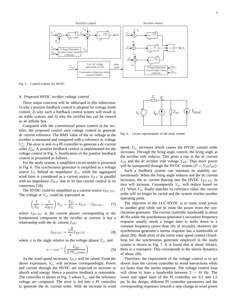
The control diagram of the HVDC is shown in Fig. 5.Controls are implemented for both the rectifier and the inverter.For inverter control, there are three types of modes constantdc voltage, constant extinction angle and constant dc current.PI controllers are implemented to regulate dc voltage, extinc-tion angle or dc current. Voltage dependent current limiter(VDCL) will be enforced when the dc voltage drops due toac disturbances [5], [6]. For this study system, the HVDC
inverter is operated at the constant voltage control mode atnormal operating conditions.
The rectifier is normally operated at the constant currentcontrol mode where the dc current measurement is comparedwith a dc current order to generate desired firing angle. Apositive feedback PI controller is adopted due to the LCC-HVDC characteristic. A brief description is as follows. Therelationship among the firing angleαR of the rectifier, rectifierside ac voltage magnitudeVac, dc voltageVdr and dc currentIdR is expressed as:
Vdr = 2.7VaccosαR − IdR ∗Rc (5)
Also the voltage and current relationship of the dc line is asfollows:
Vdr = Vdi + IdR ∗Rdc. (6)
whereVdi is the inverter side dc voltage. ThereforeIdR =2.7VaccosαR−Vdi
Rc+Rdc. Assume thatVac andVdi are constant. If the
firing angleα increases,IdR decreases. Therefore, a positivefeedback control is reasonable. To improve the dc current, thefiring angle should be reduced. The measured dc current iscompared with the dc current reference and the error signalis fed into a PI controller (shown in Fig. 5). The outputof the controller is the firing angle at the rectifier sideαR.In traditional HVDC rectifier control, this current order isgenerated by the dc power order divided by the dc voltage.The bandwidth of the current order control for LCC-HVDCsystem is at least 40 Hz [10].
When there is an ac system fault, the inverter may notbe able to recover itself due to commutation failure. In suchcases, it is important to reduce the stress on the inverter valves.This is achieved by reducing the rectifier side dc voltagevdr.When the rectifier side dc voltagevdr reaches a limitVdLR
,the voltage dependent current order limiter (VDCOL) startsto work. The VDCOL reduces the current setting when thevoltage decreases.
The traditional power scheduling way to adjust the currentorder is not feasible for the purpose of fast power routingwith wind power involved. Since wind power is fluctuating,a constant power schedule is difficult to implement. In thispaper, a new rectifier control is proposed for the HVDC tofollow the fluctuating wind power and route the wind powerto a grid.
4
*
acVdRI
R ! !
*
dRI
Inverter control
I
dIV
!
*
dIV
dII
*
dII
!*
Rectifier control
s
450045
s
225025
s
402
s
450045
limIdrefI
RdLV _
Voltage Dependent
Current Order Limiter
(VDCOL)
limIdrefI
IdLV _
Voltage Dependent
Current Order Limiter
(VDCOL)
acV
s
kk ip
Low AC voltage
detection(LACVD)
Commutation failure prevention
control(CFPREV)
IabcV _
angle
signal
Fig. 5. Control scheme for HVDC.
A. Proposed HVDC rectifier voltage control
Three major concerns will be addressed in this subsection:1) why a positive feedback control is adopted for voltage modecontrol; 2) why such a feedback control system will result inan stable system; and 3) why the rectifier bus can be viewedas an infinite bus.
Compared with the conventional power control at the rec-tifier, the proposed control uses voltage control to generatedc current reference. The RMS value of the ac voltage at therectifier is measured and compared with a reference ac voltageV ∗
ac. The error is sent to a PI controller to generate a dc currentorderI∗dR. A positive feedback control is implemented for thevoltage control in Fig. 5. Justification of the positive feedbackcontrol is presented as follows.
For the study system, a simplified circuit model is presentedin Fig. 6. The synchronous generator is simplified as a voltagesourceVG behind an impedanceZG, while the aggregatedwind farm is considered as a current sourceIWF in parallelwith an impedanceZWF due to its fast current control in itsconverters [18].
The HVDC could be simplified as a current sourceIHV DC .The voltage atVac could be expressed as:
(
1
ZG
+1
ZWF
)
Vac =VG
ZG
+ IWF − IHV DC . (7)
where IHV DC is the current phasor corresponding to thefundamental component in the rectifier ac current. It has arelationship with the dc currentIdR:
IHV DC =
√6
πIdR∠φ (8)
whereφ is the angle relative to the voltage phasorVac and
φ = cos−1
(
VdR
2.7Vaccosα
)
(9)
As the wind speed increases,IWF will be raised. From theabove expression,Vac will increase correspondingly. Powerand current through the HVDC are expected to increase toabsorb wind energy. Hence a positive feedback is reasonable.The controller is shown in Fig. 5 whereVac and the referencevoltage are compared. The error is fed into a PI controllerto generate the dc current order. With an increase in wind
WFIGV HVDCI
GZ
WFZ
acV
Fig. 6. Circuit representation of the study system.
speed,Vac increases which causes the HVDC current orderincreases. Through the firing angle control, the firing angleatthe rectifier side reduces. This gives a rise in the dc currentIdR and the dc rectifier side voltageVdR. Thus more powerwill be transported through the HVDC system (P = VdRIdR).
Such a feedback system can maintain its stabilityau-tonomously. When the firing angle reduces and the dc currentincreases, the ac current flowing into the HVDCIHV DC inturn will increase. ConsequentlyVac will reduce based on(1). WhenVac finally matches its reference value, the currentorder will no longer be varied and the system reaches anotheroperating point.
The objective of the LCC-HVDC is to route wind powerto another grid while not to route the power from the syn-chronous generator. The current controller bandwidth is about40 Hz while the synchronous generator’s secondary frequencyresponse usually needs a longer time to settle down to aconstant frequency (more than 10s of seconds). However thesynchronous generator’s inertia response has a bandwidth ofabout 2Hz. Bode plots of the entire rotor speed control closed-loop for the synchronous generator employed in the studysystem is shown in Fig. 7. It is found that at about 10rad/s,there is a resonance. This corresponds to the inertia dynamicsof about 2Hz.
Therefore, the requirement of the voltage control is to actslower than the current controller to avoid interactions whileact faster than the inertia response. The voltage control loopwill chose to have a bandwidth between2 ∼ 40 Hz. Thelower and upper limit of the PI controller are 0.5 and 1.5pu. In the design, different PI controller parameters and thecorresponding responses towards a step change in wind power
5
or load will be examined. In Fig. 11 in the next section, it willbe demonstrated that when the voltage control acts faster tofacilitate absorbing wind power change, the inertia responseof the synchronous generator subjects to less power swingand frequency deviation. A less frequency deviation in turnwill lead to a much less power sharing from the synchronousgenerator.
100
101
102
103
−120
−100
−80
−60
−40
−20
0
From: sgtest0319/wref To: <Rotor speed wm (pu)>
Mag
nitu
de (
dB)
Bode Diagram
Frequency (rad/sec)
Fig. 7. Bode plot of the synchronous generator’s frequency control closed-loop system when the generator is connected to an infinite bus.
IV. SIMULATION STUDIES
To demonstrate the power routing capability of the HVDC,simulation studies are carried out in Matlab/SimPowerSystems[13]. The study system is shown in Fig. 1. The synchronousgenerator supplies power to the HVDC (at about 500 MW)and the local load (420 MW). The DFIG-based wind farm isan aggregated system rated at 510 MW. Four case studies aredesigned. Case study 1 tests the voltage control step response.Case Study 2 tests HVDC’s fast power routing capability whenthe wind speed changes. Case Study 3 tests HVDC’s fastpower routing capability when there is a change in loads andwhen the synchronous generator picks up the load change.Case Study 4 tests ac fault recovery of the HVDC system.
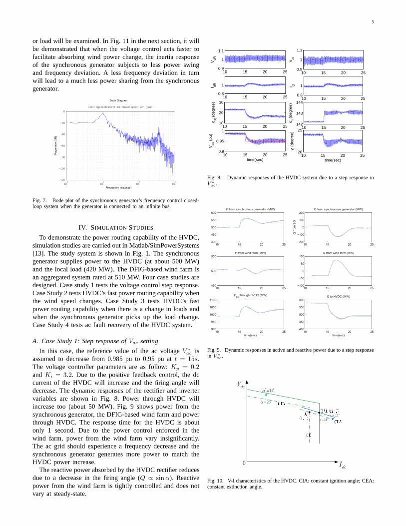
A. Case Study 1: Step response ofVac setting
In this case, the reference value of the ac voltageV ∗
ac isassumed to decrease from 0.985 pu to 0.95 pu att = 15s.The voltage controller parameters are as follow:Kp = 0.2andKi = 3.2. Due to the positive feedback control, the dccurrent of the HVDC will increase and the firing angle willdecrease. The dynamic responses of the rectifier and invertervariables are shown in Fig. 8. Power through HVDC willincrease too (about 50 MW). Fig. 9 shows power from thesynchronous generator, the DFIG-based wind farm and powerthrough HVDC. The response time for the HVDC is aboutonly 1 second. Due to the power control enforced in thewind farm, power from the wind farm vary insignificantly.The ac grid should experience a frequency decrease and thesynchronous generator generates more power to match theHVDC power increase.
The reactive power absorbed by the HVDC rectifier reducesdue to a decrease in the firing angle (Q ∝ sinα). Reactivepower from the wind farm is tightly controlled and does notvary at steady-state.
10 15 20 250.9
1
1.1
VdI
10 15 20 250.8
1I dI
10 15 20 25142
143
144
α I (de
gree
)
10 15 20 2520
25
γ I (de
gree
)
time(sec)
10 15 20 250.9
1
1.1
VdR
10 15 20 250.8
1I dR
10 15 20 2510
20
30
α R (
degr
ee)
10 15 20 250.9
0.95
1
Vac
(pu
)
time(sec)
Fig. 8. Dynamic responses of the HVDC system due to a step response inV ∗
ac.
10 15 20 25400
450
500
550
600P from synchronous generator (MW)
10 15 20 25450
500
550P from wind farm (MW)
10 15 20 25900
950
1000
1050
1100
Pdc
through HVDC (MW)
time(sec)
10 15 20 25−200
−100
0
100
200Q from synchronous generator (MW)
Q f
rom
SG
10 15 20 25−100
−50
0
50
100Q from wind farm (MW)
10 15 20 25400
450
500
550
600Q to HVDC (MW)
time(sec)
Fig. 9. Dynamic responses in active and reactive power due toa step responsein V ∗
ac.
dcI
dcV
023
0' 14
024
022
Fig. 10. V-I characteristics of the HVDC. CIA: constant ignition angle; CEA:constant extinction angle.

6
The dc currents increase and the rectifier firing angledecreases due to the step response. The relationship of thedc voltage and current is shown in Fig. 10. An increase in theac voltage results in an increase inVdc0 the cross point of therectifier CIA line and the Y-axis. The inverter is at constantvoltage control. While the original operating condition isatpoint A, due to the increase of the dc current, the operatingpoint moves to B. Inverter dc voltage levels at A and B arekept same. Extinction angleγ will decrease when the operatingpoint moves from A to B. Hence in Fig. 8, we can also observethatγ decreases due to a reduction in the ac voltage referencevalue.
B. Case Study 2: Wind speed change
A varying wind speed is the main characteristic of windenergy. In this case, the power routing capability of HVDCis tested for a varying wind speed. The voltage controlleris the key for the HVDC to pick up power change underdifferent wind speeds. However, different PI parameter settingscan affect the power sharing of the DFIG, the synchronousgenerator and the HVDC. When the time constant of thevoltage controller is small, the HVDC will pick up all thepower change when the wind speed changes. When the timeconstant of the PI controller is large, the synchronous generatorand HVDC will share the power change. Fig. 11 shows thecomparison of two cases with different time constants. In (a),the parameters areKp = 0.7, Ki = 0.9, and the time constantτ = 0.76. The synchronous generator and the HVDC will pickup the power change from the DFIG together. The share ofthe synchronous generator is about 15 MW. In (b),Kp = 0.2,Ki = 3.2, and the time constantτ = 0.0625. The HVDC actsfast enough to pick up all the power change from the windfarm.
15 20 25 30 35 40450
500
550
600
P fr
om S
G(M
W)
15 20 25 30 35 40850
900
950
1000
time(sec)
Pdc
(MW
)
Kp=0.7,K
i=0.9
Kp=0.2,K
i=3.2
Kp=0.2,K
i=3.2
Kp=0.7,K
i=0.9
Fig. 11. Dynamic responses of active power from synchronousgenerator,through HVDC due to a change in wind speed under different PI controllersettings.
From Fig. 12, it is found that in Case b the response ofVac
is much faster compared to that in Case a. Therefore a fastervoltage control can avoid power sharing by the synchronousgenerator.
15 20 25 30 35 40350
400
450
500
550
P fr
om W
F (
MW
15 20 25 30 35 400.92
0.94
0.96
0.98
1
Vac
(pu
time(sec)
Kp=0.2,K
i=3.2
Kp=0.7,K
i=0.9
Fig. 12. Dynamic responses of active power from DFIG andVac due to achange in wind speed under different PI controller settings.
A more complicated case is presented as follows. Thecontroller parameters are chosen to beKp = 0.2, Ki = 3.2.The wind speed drops from 15 m/s to 12 m/s at 10 seconds. Itthen increases from 12 m/s to 17 m/s at 20 seconds. Dynamicresponses of the power from the generator, the wind farm andthrough the HVDC are given in Fig. 13. The generator speedand the mechanical power are shown in Fig 14. The inputvariableVac and output variableIdref of the controller areshown in Fig. 14. The HVDC variables are shown in Fig. 15and the DFIG system variables are shown in Fig. 16.
At t = 10 second, the wind speed drops from 15m/s to12m/s. A drop in wind speed leads to a drop in wind farmactive power export (Fig. 13), a decrease of the HVDC rectifierside ac voltageVac (Fig. 14), a decrease of the dc current orderIdref (Fig. 14) and the dc currentId (Fig. 15), an increasein the firing angleαR (Fig. 15) and a decrease of HVDCdelivered powerPdc (Fig. 13). The response of the HVDCpower has a delay compared to the response of the wind farmpower. The synchronous generator has an initial increase ofpower export to balance the total power by releasing kineticenergy from its rotating mass. This leads to the reduction ofits rotating speed. The turbine governor senses the change inrotating speed and generator power and adjusts its mechanicalpower based on the error signal.
The DFIG pitch angle will become zero when the windspeed reduces below the synchronous speed.
C. Case Study 3: Load change
In Case Study 3, the load increases from 420 MW to 520MW at 10s. The HVDC picks up the load change immediatelysince the response of the HVDC is faster than the synchronousgenerator. Due to the slow turbine governor response, a changein the reference powerPref will be reflected in the generatorpower after about 30 seconds. In order to show the HVDCresponse in this simulation case, the mechanical power of thesynchronous generator is assumed to have an increase of 100MW at 15 seconds. The synchronous generator will increase

7
5 10 15 20 25 30400
500
600P from the synchronous generator (MW)
5 10 15 20 25 30200
400
600P from the wind farm (MW)
5 10 15 20 25 30800
1000
1200
Pdc
of the HVDC
time(sec)
Fig. 13. Dynamic responses of the real power from the synchronous generator(excluding the load), the wind farm and through the HVDC due to wind speedchanges.
5 10 15 20 25 300.9
1
1.1
input of the controller Vac
(pu)
5 10 15 20 25 300.8
1
1.2
output of the controller Idref
(pu)
5 10 15 20 25 300.98
1
1.02
speed of the synchronous generator ωm
(pu)
5 10 15 20 25 300.9
0.92
0.94
mechanical power of the synchronous generator Pm
(pu)
time(sec)
Fig. 14. Dynamic responses of the voltage controller and theturbine governordue to wind speed changes.
its power output to pick up the load change. Consequently,the dc power will be reduced to its original level. Dynamicresponses of the system are shown in Figs. 17 and 18.
The synchronous generator speed will decrease when theload increases and will increase when the synchronous gener-ator increases its output power. Increased load however affectsthe system voltage level.Vac will decrease. This in turn willtrigger the voltage controller to decrease the dc current orderand increase the firing angle. When the synchronous generatorstarts to pick up the load increase, the voltage level increases.The HVDC system will then ramp up its transporting powerthrough decreasing the rectifier firing angleα.
5 10 15 20 25 300.5
1
1.5
dc voltage of the rectifier VdR
(pu)
5 10 15 20 25 300.5
1
1.5
dc current of the rectifier IdR
(pu)
5 10 15 20 25 3010
20
30
firing angle of the rectifier αR
(degree)
5 10 15 20 25 30135
140
145
firing angle of the inverter αI (degree)
5 10 15 20 25 3020
25
30
extinction angle of the inverter γI (degree)
time(sec)
Fig. 15. Dynamic responses of the HVDC due to wind speed changes.
5 10 15 20 25 30−1
−0.8
−0.6DFIG variables
Tm
(pu
)
5 10 15 20 25 30−1
−0.8
−0.6
Te (
pu)
5 10 15 20 25 301.1
1.2
1.3
ωr (
pu)
5 10 15 20 25 300
10
20
pitc
h an
gle
(deg
ree)
5 10 15 20 25 301100
1150
1200
Vdc
(V
)
time(sec)
Fig. 16. Dynamic responses of the DFIG wind farm due to wind speedchanges.

8
9 10 11 12 13 14 15 16 17 18 19 20300
400
500
600P absorbed by the load (MW)
9 10 11 12 13 14 15 16 17 18 19 20900
1000
1100
Pref
of the synchronous generator(MW)
9 10 11 12 13 14 15 16 17 18 19 20800
900
1000
1100P from synchronous generator (MW)
9 10 11 12 13 14 15 16 17 18 19 20800
900
1000
1100
Pdc
through HVDC line (MW)
time(sec)
Fig. 17. Dynamic responses of the active power from synchronous generator,load, DFIG and through HVDC due to a load change.
9 10 11 12 13 14 15 16 17 18 19 200.995
1
1.005
Synchronous Generator variables ωm
(pu)
9 10 11 12 13 14 15 16 17 18 19 2010
20
30
firing angle of the rectifier αR
(degree)
9 10 11 12 13 14 15 16 17 180.8
1
1.2
dc current of the rectifier IdR
(pu)
9 10 11 12 13 14 15 16 17 18 19 200.95
1
1.05
input the controller Vac
(pu)
time (sec)
Fig. 18. Dynamic responses of the generator speed, firing angle, dc voltageandVac due to load change.
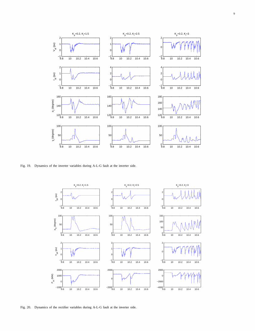
D. Case Study 4: AC fault recovery
The operation of an HVDC is often affected by disturbancessuch as faults on the ac system. In Case Study 4, a single-line-to-ground (S-L-G) fault on the inverter ac system is studied.A S-L-G fault is applied on phase A at 10 s, and is clearedat 10.1 s. The fault will cause the reduction of the ac voltageand raise of the dc current as shown in Fig. 19. Due to thefailure of the commutation from one valve to another beforethe commutating voltage reverses, commutation failure occurs
at the very beginning of the fault. The commutation failurewill lead to short circuit across the valve group. The dc poweris almost zero as shown in Fig. 20. After the fault is cleared,the system returns to normal operation after about 0.2 s.
As shown in Case Study 2, the parameters of the volt-age control affect system dynamics. The impact of the PIparameters on ac fault recovery performance is also studied.If the integration constantKi increases, the settling time ofthe system will increase [19]. Therefore, the dynamics of thedc current and firing angle of the rectifier will be affectedunder different integration constants. Figs. 19 and 20 showthat whenKi = 3, the system can not recovery after the faultclearance. Therefore, the two other two sets of parametersKp = 0.2/Ki = 1.5 and Kp = 0.2/Ki = 2 are better interms of ac fault recovery.
In Case Study 2, a smaller time constant is demonstrated tobe good for HVDC to do fast power routing task. However,Case Study 4 shows that a smaller time constant for the PIcontroller may cause ac fault recovery problems. Therefore,the controller parameters have to be chosen and verifiedthrough various studies.
V. CONCLUSION
This paper investigates the fast power routing capability ofLCC-HVDC. A positive feedback control loop is introducedin the rectifier control to produce the dc current order. Mat-lab/SimPowersystems based simulation for an ac/dc systemwith wind power penetration confirms the effectiveness ofsuch control scheme. In addition, ac fault recovery is in-vestigated for an LCC-HVDC equipped with the proposedcontrol scheme. The proposed technology can help realize fastpower routing through LCC-HVDC in future grid with highpenetration of intermittent renewable energy resources.
APPENDIX
TABLE IPARAMETERS OF THEDFIG WIND FARM
Total capacity 333*1.5MWNominal voltage 575V
Frequency 60Hzrs (pu) 0.023rr (pu) 0.18Xls (pu) 0.016Xlr (pu) 0.16XM (pu) 2.9H (kg.m2) 0.685F (pu) 0.01p (poles) 3
REFERENCES
[1] P. Bresesti, W. Kling, R. Hendriks, and R. Vailati, “HVDCconnectionof offshore wind farms to the transmission system,”IEEE Trans. EnergyConvers., vol. 22, no. 1, pp. 37 –43, Mar. 2007.
[2] L. Xu and B. R.Andersen, “Grid connection of large offshore wind farmsusing HVDC,” Wind Energy, vol. 9, no. 4, pp. 371–382, Dec. 2005.
[3] L. Xu, L. Yao, and C. Sasse, “Grid integration of large DFIG-basedwind farms using VSC transmission,”IEEE Trans. Power Syst., vol. 22,no. 3, pp. 976 –984, Aug. 2007.
9
9.8 10 10.2 10.4 10.6−1
0
1
2
Kp=0.2, K
i=1.5
VdI
(pu
)
9.8 10 10.2 10.4 10.6−1
0
1
2
I dI (
pu)
9.8 10 10.2 10.4 10.6120
140
160
α I (de
gree
)
9.8 10 10.2 10.4 10.60
50
100
γ I (de
gree
)
9.8 10 10.2 10.4 10.6−1
0
1
2
Kp=0.2, K
i=2.5
9.8 10 10.2 10.4 10.6−2
0
2
4
9.8 10 10.2 10.4 10.6120
140
160
9.8 10 10.2 10.4 10.60
50
100
9.8 10 10.2 10.4 10.6−2
0
2
Kp=0.2, K
i=3
9.8 10 10.2 10.4 10.6−2
0
2
4
9.8 10 10.2 10.4 10.6120
140
160
180
9.8 10 10.2 10.4 10.60
50
100
Fig. 19. Dynamics of the inverter variables during A-L-G fault at the inverter side.
9.8 10 10.2 10.4 10.6−2
0
2
Kp=0.2, K
i=1.5
I dR (
pu)
9.8 10 10.2 10.4 10.60
50
100
α R (
degr
ee)
9.8 10 10.2 10.4 10.6−1
0
1
2
VdR
(pu
)
9.8 10 10.2 10.4 10.6−1000
0
1000
2000
Pdc
(M
W)
9.8 10 10.2 10.4 10.6−2
0
2
Kp=0.2, K
i=2.5
9.8 10 10.2 10.4 10.60
50
100
9.8 10 10.2 10.4 10.6−1
0
1
2
9.8 10 10.2 10.4 10.6−2000
0
2000
9.8 10 10.2 10.4 10.6−2
0
2
Kp=0.2, K
i=3
9.8 10 10.2 10.4 10.60
50
100
150
9.8 10 10.2 10.4 10.6−2
0
2
9.8 10 10.2 10.4 10.6−4000
−2000
0
2000
Fig. 20. Dynamics of the rectifier variables during A-L-G fault at the inverter side.

10
[4] N. Flourentzou, V. Agelidis, and G. Demetriades, “VSC-based HVDCpower transmission systems: an overview,”IEEE Trans. Power Electron.,vol. 24, no. 3, pp. 592 –602, March 2009.
[5] V. K. Sood, HVDC and FACTS Controllers:Applications of StaticConverters in Power Systems. Springer, 2004.
[6] P. Kundur,Power System Stability and Control. McGraw Hill, 1994.[7] S. Bozhko, R. Blasco-Gimenez, R. Li, J. Clare, and G. Asher, “Control
of offshore DFIG-based wind farm grid with line-commutatedHVDCconnection,”IEEE Trans. Energy Convers., vol. 22, no. 1, pp. 71 –78,Mar. 2007.
[8] D. Xiang, L. Ran, J. Bumby, P. Tavner, and S. Yang, “Coordinatedcontrol of an HVDC link and doubly fed induction generators in a largeoffshore wind farm,”IEEE Trans. Power Del., vol. 21, no. 1, pp. 463 –471, Jan. 2006.
[9] R. Li, S. Bozhko, and G. Asher, “Frequency control designfor offshorewind farm grid with LCC-HVDC link connection,”IEEE Trans. PowerElectron., vol. 23, no. 3, pp. 1085 –1092, May 2008.
[10] S. Bozhko, G. Asher, R. Li, J. Clare, and L. Yao, “Large offshore DFIG-based wind farm with line-commutated HVDC connection to themaingrid: Engineering studies,”IEEE Trans. Energy Convers., vol. 23, no. 1,pp. 119 –127, 2008.
[11] S. Foster, L. Xu, and B. Fox, “Control of an lcc hvdc system forconnecting large offshore wind farms with special consideration of gridfault,” in Power and Energy Society General Meeting - Conversion andDelivery of Electrical Energy in the 21st Century, 2008 IEEE, july 2008,pp. 1 –8.
[12] H. Zhou, G. Yang, and J. Wang, “Modeling, analysis, and control forthe rectifier of hybrid HVdc systems for DFIG-based wind farms,” IEEETrans. Energy Convers., vol. 26, no. 1, pp. 340 –353, Mar. 2011.
[13] SimpowersystemsTM . Mathworks. [Online]. Available:http://www.mathworks.com/help/toolbox/physmod/powersys/powersysproduct page.html
[14] SimpowersystemsTM - hydraulic turbine andgovernor. Mathworks. [Online]. Available:http://www.mathworks.com/help/toolbox/physmod/powersys/ref/hydraulicturbineandgovernor.html
[15] “Modeling of ge wind turbine-generators for grid studies,” GeneralElectric International, Inc, Schenectady, New York, Tech.Rep., 2005.
[16] T. K. A. Brekken and N. Mohan, “Control of a doubly fed inductionwind generator under unbalanced grid voltage conditions,”IEEE Trans.Energy Convers., vol. 22, no. 1, pp. 129–135, Mar. 2007.
[17] R. Pena, J. Clare, and G. Asher, “Doubly fed induction generator usingback-to-back pwm converters and its application to variable-speed wind-energy generation,”Proc. Inst. Elect. Eng. Elect. Power Appl., vol. 143,no. 3, pp. 231–241, 1996.
[18] “Modeling of GE wind turbine-generators for gid studies,” GE Energy,Schenectady, NY, Tech. Rep., Mar. 2005.
[19] PID tutorial. The University of Michigan. [Online]. Available:http://www.engin.umich.edu/group/ctm/PID/PID.html#introduction
Haiping Yin ’09’09S received a Ph.D. degree inElectrical Engineering from University of SouthFlorida in 2011. Currently she is an engineer at PWRSolutions at Dallas Texas. Her research interests in-clude modeling and control of wind energy systems,electrical power systems and HVDC transmission.
Lingling Fan (SM’08) received the B.S. and M.S.degrees in electrical engineering from SoutheastUniversity, Nanjing, China, in 1994 and 1997, re-spectively, and the Ph.D. degree in electrical engi-neering from West Virginia University,Morgantown,in 2001.
Currently, she is an Assistant Professor with theUniversity of South Florida, Tampa, where she hasbeen since 2009. She was a Senior Engineer inthe Transmission Asset Management Department,Midwest ISO, St. Paul, MN, form 2001 to 2007, and
an Assistant Professor with North Dakota State University,Fargo, from 2007to 2009. Her research interests include power systems and power electronics.
Zhixin Miao (S00M03SM09) received the B.S.E.E.degree from the Huazhong University of Science andTechnology,Wuhan, China, in 1992, the M.S.E.E.degree from the Graduate School, Nanjing Automa-tion Research Institute¡ Nanjing, China, in 1997, andthe Ph.D. degree in electrical engineering from WestVirginia University, Morgantown, in 2002.
Currently, he is with the University of SouthFlorida (USF), Tampa. Prior to joining USF in 2009,he was with the Transmission Asset ManagementDepartment with Midwest ISO, St. Paul, MN, from
2002 to 2009. His research interests include power system stability, microgrid,and renewable energy.