Fast Packet Retransmissions in LTE - DiVA...
78
Institutionen för systemteknik Department of Electrical Engineering Examensarbete Fast Packet Retransmissions in LTE Examensarbete utfört i Kommunikationssystem vid Tekniska högskolan i Linköping av Serkan Demir och Syed-Tamoor-ul-Hassan LiTH-ISY-EX--11/4529--SE Linköping 2011 Department of Electrical Engineering Linköpings tekniska högskola Linköpings universitet Linköpings universitet SE-581 83 Linköping, Sweden 581 83 Linköping
Transcript of Fast Packet Retransmissions in LTE - DiVA...

Institutionen för systemteknikDepartment of Electrical Engineering
Examensarbete
Fast Packet Retransmissions in LTE
Examensarbete utfört i Kommunikationssystemvid Tekniska högskolan i Linköping
av
Serkan Demir och Syed-Tamoor-ul-Hassan
LiTH-ISY-EX--11/4529--SE
Linköping 2011
Department of Electrical Engineering Linköpings tekniska högskolaLinköpings universitet Linköpings universitetSE-581 83 Linköping, Sweden 581 83 Linköping

Fast Packet Retransmissions in LTE
Examensarbete utfört i Kommunikationssystemvid Tekniska högskolan i Linköping
av
Serkan Demir och Syed-Tamoor-ul-Hassan
LiTH-ISY-EX--11/4529--SE
Handledare: Reza Moosaviisy, Linköpings universitet
Kristina JerseniusEricsson AB
Examinator: Jonas Erikssonisy, Linköpings universitet
Linköping, 28 October, 2011


Avdelning, InstitutionDivision, Department
Division of Communication SystemsDepartment of Electrical EngineeringLinköpings universitetSE-581 83 Linköping, Sweden
DatumDate
2011-10-28
SpråkLanguage
� Svenska/Swedish� Engelska/English
�
�
RapporttypReport category
� Licentiatavhandling� Examensarbete� C-uppsats� D-uppsats� Övrig rapport�
�
URL för elektronisk versionhttp://www.commsys.isy.liu.se
http://www.ep.liu.se
ISBN—
ISRNLiTH-ISY-EX--11/4529--SE
Serietitel och serienummerTitle of series, numbering
ISSN—
TitelTitle
Snabba paketåtersändningar i LTEFast Packet Retransmissions in LTE
FörfattareAuthor
Serkan Demir och Syed-Tamoor-ul-Hassan
SammanfattningAbstract
The cellular networks are evolving to meet the future requirements of data rate,coverage and capacity. The fourth generation mobile communication system, LTEhas been developed to meet these goals. LTE uses multiple antenna features andlarger bandwidths in order to accomplish this task. These features will furtherextend the requirements of data rate, coverage, latency and flexibility.LTE also utilizes the varying quality of the radio channel and the interferencefrom other transmitters by adapting the data rate to the instantaneous channelquality at all the time. This is typically referred to as Link Adaptation. Thelink adaptation fails from time to time due to the varying channel quality as wellas the interference from other transmitters. In order to counteract these failures,retransmission methods are employed. These methods detect the errors on thereceiver side and signals the transmitter for the retransmission of the erroneousdata. The efficiency of link adaptation increases if combined with a properly de-signed retransmission scheme at the expense of delays due to retransmissions.This master thesis focuses on the study of the retransmission schemes with fasterfeedback, resulting in a reduction in delay. The feedback is generated by makingan early estimate of the decoding outcome and sending it early to the transmitterresulting in faster retransmission. This is important in certain applications wherethe data transmission is intolerant to delays.The thesis work shows by system performance simulations that fast packet retrans-mission, precisely called Early HARQ Feedback, significantly affects the systemperformance together with the utilization of the link adaptation. The study alsoshows that the link adaptation, in certain scenarios, can be optimized to improvethe system performance. In that respect, it is also possible to increase the numberof retransmissions within the same resource utilization. That optimization is ba-sically called aggressive link adaptation. Consequently, Early HARQ Feedback incombination with aggressive link adaptation provides a large improvement in thedownlink performance of the studied cases.
NyckelordKeywords Link Adaptation, HARQ, EHF, FTP, VOIP


AbstractThe cellular networks are evolving to meet the future requirements of data rate,coverage and capacity. The fourth generation mobile communication system, LTEhas been developed to meet these goals. LTE uses multiple antenna features andlarger bandwidths in order to accomplish this task. These features will furtherextend the requirements of data rate, coverage, latency and flexibility.LTE also utilizes the varying quality of the radio channel and the interferencefrom other transmitters by adapting the data rate to the instantaneous channelquality at all the time. This is typically referred to as Link Adaptation. Thelink adaptation fails from time to time due to the varying channel quality as wellas the interference from other transmitters. In order to counteract these failures,retransmission methods are employed. These methods detect the errors on thereceiver side and signals the transmitter for the retransmission of the erroneousdata. The efficiency of link adaptation increases if combined with a properly de-signed retransmission scheme at the expense of delays due to retransmissions.This master thesis focuses on the study of the retransmission schemes with fasterfeedback, resulting in a reduction in delay. The feedback is generated by makingan early estimate of the decoding outcome and sending it early to the transmitterresulting in faster retransmission. This is important in certain applications wherethe data transmission is intolerant to delays.The thesis work shows by system performance simulations that fast packet retrans-mission, precisely called Early HARQ Feedback, significantly affects the systemperformance together with the utilization of the link adaptation. The study alsoshows that the link adaptation, in certain scenarios, can be optimized to improvethe system performance. In that respect, it is also possible to increase the numberof retransmissions within the same resource utilization. That optimization is ba-sically called aggressive link adaptation. Consequently, Early HARQ Feedback incombination with aggressive link adaptation provides a large improvement in thedownlink performance of the studied cases.
v


Acknowledgments
Serkan Demir:
I would like to thank my supervisor Kristina Jersenius and Gunnar Bark,manager at Ericsson Research for their valuable support during the thesis work. Iam also grateful to all members of LINLAB at Ericsson Radio Access Technology.It was a great experience to be with such great engineers.I would also like to show my gratitude to my examiner, Jonas Eriksson andmy supervisor, Reza Moosavi at Linköping University for their encouragementand advices. I am also thankful to my colleague, Syed-Tamoor-ul-Hassan. Hiscontribution was really important to complete the thesis work.Finally, special thanks to my family and friends for their support during thethesis work.
Syed-Tamoor-ul-Hassan:
First of all, I would like to thank my father, my mother, my foster-mother,my brother and sisters for supporting, helping and praying for my success.I would like to especially thank Gunnar Bark, manager at Ericsson, for giving mea chance to perform the thesis at Ericsson Research and gain experience in aninternational organization.Also, i am very greatful to my examiner and my supervisors, at Ericsson andLinköping university for the help that they extended to me during the course ofthe thesis.Last but not the least, i am also thankful to my project member, Serkan Demirfor having a good time during the thesis and the support during the thesis work.
vii


Contents
1 Introduction 11.1 Background . . . . . . . . . . . . . . . . . . . . . . . . . . . . . . . 11.2 Purpose and Goals . . . . . . . . . . . . . . . . . . . . . . . . . . . 21.3 Disposition . . . . . . . . . . . . . . . . . . . . . . . . . . . . . . . 2
2 LTE Overview 32.1 Technologies behind LTE . . . . . . . . . . . . . . . . . . . . . . . 3
2.1.1 Orthogonal Frequency Division Muliplexing (OFDM) . . . 42.1.2 Scheduling . . . . . . . . . . . . . . . . . . . . . . . . . . . 42.1.3 Multiple Antenna Support . . . . . . . . . . . . . . . . . . . 72.1.4 Spectrum Flexibility . . . . . . . . . . . . . . . . . . . . . . 8
2.2 Downlink Reference Signals . . . . . . . . . . . . . . . . . . . . . . 82.3 LTE Time Domain Structure . . . . . . . . . . . . . . . . . . . . . 102.4 LTE Radio Access Interface . . . . . . . . . . . . . . . . . . . . . . 10
3 Link Adaptation 133.1 Channel Estimation . . . . . . . . . . . . . . . . . . . . . . . . . . 14
3.1.1 Channel Quality Indicator Reporting . . . . . . . . . . . . . 143.1.2 Methods of Channel Estimation . . . . . . . . . . . . . . . . 15
3.2 Variations of Link Adaptation . . . . . . . . . . . . . . . . . . . . . 17
4 Aggressive Link Adaptation 194.1 Block Error Rate Target . . . . . . . . . . . . . . . . . . . . . . . . 204.2 MCS Table Based Downlink Adaptation . . . . . . . . . . . . . . . 204.3 100% BLER target for initial transmission and 10% BLER for other
transmissions (Aggressive100) . . . . . . . . . . . . . . . . . . . . . 204.4 30% BLER target for initial transmission and 10% BLER for other
transmissions (Aggressive30) . . . . . . . . . . . . . . . . . . . . . 21
5 Retransmission Methods 235.1 Automatic Repeat Request . . . . . . . . . . . . . . . . . . . . . . 23
5.1.1 Stop and Wait ARQ . . . . . . . . . . . . . . . . . . . . . . 235.1.2 Go-Back-N ARQ . . . . . . . . . . . . . . . . . . . . . . . . 235.1.3 Selective Repeat ARQ . . . . . . . . . . . . . . . . . . . . . 245.1.4 N-channel Stop and Wait ARQ . . . . . . . . . . . . . . . . 25
ix

x Contents
5.2 Hybrid Automatic Repeat Request . . . . . . . . . . . . . . . . . . 265.3 Hybrid Automatic Repeat Request Types . . . . . . . . . . . . . . 26
5.3.1 Hybrid Automatic Repeat Request Type 1 . . . . . . . . . 265.3.2 Hybrid Automatic Repeat Request Type 2 . . . . . . . . . 27
5.4 HARQ Classification based on Timing . . . . . . . . . . . . . . . . 275.5 HARQ Classification based on Adaptation . . . . . . . . . . . . . . 275.6 HARQ Combining Methods . . . . . . . . . . . . . . . . . . . . . . 28
5.6.1 Chase Combining . . . . . . . . . . . . . . . . . . . . . . . . 285.6.2 Incremental Redundancy . . . . . . . . . . . . . . . . . . . 28
5.7 HARQ in LTE . . . . . . . . . . . . . . . . . . . . . . . . . . . . . 28
6 Early HARQ Feedback 316.1 Potential Benefits . . . . . . . . . . . . . . . . . . . . . . . . . . . . 31
6.1.1 Expected Results for Delay-sensitive Traffic . . . . . . . . . 316.1.2 Expected Results for Delay-tolerant Traffic . . . . . . . . . 32
6.2 Configurations for Simulations . . . . . . . . . . . . . . . . . . . . 326.2.1 Conventional HARQ . . . . . . . . . . . . . . . . . . . . . . 336.2.2 Early HARQ Feedback . . . . . . . . . . . . . . . . . . . . . 336.2.3 Extremely Short HARQ . . . . . . . . . . . . . . . . . . . . 34
7 Algorithms and Implementation 377.1 Early HARQ Feedback Algorithm . . . . . . . . . . . . . . . . . . . 37
7.1.1 Early HARQ Feedback Properties . . . . . . . . . . . . . . 377.1.2 EHF Operation in Downlink . . . . . . . . . . . . . . . . . 38
7.2 Implementation . . . . . . . . . . . . . . . . . . . . . . . . . . . . . 39
8 Simulation Scenarios 418.1 Macro Cell Model . . . . . . . . . . . . . . . . . . . . . . . . . . . . 418.2 Physical Layer Model . . . . . . . . . . . . . . . . . . . . . . . . . 428.3 Traffic Models . . . . . . . . . . . . . . . . . . . . . . . . . . . . . . 42
8.3.1 File Transfer Protocol . . . . . . . . . . . . . . . . . . . . . 438.3.2 Voice Over Internet Protocol . . . . . . . . . . . . . . . . . 43
8.4 Higher Layer Configuration . . . . . . . . . . . . . . . . . . . . . . 44
9 Results 459.1 Performance Measures . . . . . . . . . . . . . . . . . . . . . . . . . 45
9.1.1 File Transfer Protocol . . . . . . . . . . . . . . . . . . . . . 459.1.2 Voice Over Internet Protocol . . . . . . . . . . . . . . . . . 46
9.2 Simulation Results . . . . . . . . . . . . . . . . . . . . . . . . . . . 469.2.1 File Transfer Protocol . . . . . . . . . . . . . . . . . . . . . 469.2.2 Voice Over Internet Protocol . . . . . . . . . . . . . . . . . 56
9.3 Conclusion . . . . . . . . . . . . . . . . . . . . . . . . . . . . . . . 599.4 Future Enhancements . . . . . . . . . . . . . . . . . . . . . . . . . 61
Bibliography 63

xi

xii Contents
Abbreviations
Abbreviations DescriptionACK AcknowledgmentARQ Automatic Repeat RequestBLER Block Error RateBW BandwidthCF Carrier FrequencyCQI Channel Quality IndicatorCSI Channel State InformationEHF Early HARQ FeedbackEUTRAN Evolved UMTS terrestrial Radio Access NetworkFEC Forward Error CorrectioneNB enhanced Node BHARQ Hybrid Automatic Repeat RequestIR Incremental RedundancyLA Link AdaptationLTE Long Term EvolutionMAC Medium Access ControlMCS Modulation Coding SchemeMIMO Multiple Input and Multiple OutputNACK Negative AcknowledgmentOFDM Orthogonal Frequency Division MultiplexingOFDMA Orthogonal Frequency Division Multiple AccessPDCP Packet Data Convergence ProtocolPLoss Penetration LossQoS Quality of ServiceRLC Radio Link ControlRR Round RobinRS Reference SymbolRTT Round Trip TimeSC-FDMA Single Carrier Frequency Division Multiple AccessSCM3GPP 3GPP Spatial Channel ModelTTI Transmission Time IntervalTU Typical UrbanUE User EquipmentUMTS Universal Mobile Telecommunications SystemsVOIP Voice Over Internet Protocol

Chapter 1
Introduction
The information in this document intends to present the work and outcome of amaster thesis executed at Linköping University and Ericsson Research, Linköpingduring Spring 2011.
1.1 BackgroundThe cellular technologies for mobile communication are constantly extendingin order to meet the requirements on data rate, coverage and capacity. Manyalgorithms have been proposed to achieve this task. A remarkable improvementin data rate, coverage and capacity has been achieved over the previous twodecades in transition from second generation mobile telephony system, GlobalSystem for Mobile Communications (GSM), to the fourth generation system,Long Term Evolution (LTE). The first release of LTE adopts multiple antennatechniques and Adaptive Modulation and Coding in order to accomplish datarate requirements as well as for resourceful communication [2].
A vital tool in reaching the high peak rates is the opportunistic use of thevarying quality of the radio channel by adapting the data rate used to theinstantaneous channel quality at all times. This is known as Link Adaptation(LA). Such a scheme is bound to fail from time to time due to the stochasticnature of the channel and imperfectness in channel estimation and reporting.The interference from other transmitters also complicates the channel estimation.These failures are dealt with using retransmission methods. These methodsbasically detect the failures on the receiver side and requests a retransmissionof the corrupt data through a feedback channel. Properly designed and used, aretransmission scheme implements an efficient fine tuning of the rate adaptation,at the cost of the delays incurred by the retransmissions.
HARQ is one of the retransmission methods which is an extension of ordi-nary Automatic Repeat Request (ARQ). In ARQ, the receiver attempts to decodethe received signal. If the receiver is unable to decode the signal, it signals the
1

2 CHAPTER 1. INTRODUCTION
transmitter for retransmission. In HARQ, the receiver also decodes the receivedsignal and generates the feedback from the outcome of decoding. Meanwhile, thereceiver also stores the packet in a buffer. If the receiver fails to decode the packet,it generates a Negative Acknowledgement (NACK) and combines the signal witha new received version of the signal. This method is called soft combining. In thisway, the number of retransmissions is reduced and hence resources are utilizedmore efficiently.
As stated earlier, radio channel conditions are complex to determine for atransmission. Even though the system performance is of course affected by thevarying channel conditions, the link adaption is a crucial method to deal with theimperfections of the channels.
1.2 Purpose and GoalsThe aim of the master thesis is to assess the system performance gains by makingan early estimate of the outcome of the decoding attempt. The estimation, inthe form of Early HARQ Feedback, is sent to the transmitter at an earlier timecompared to the standard HARQ Feedback.
1.3 DispositionThe report begins with an introduction to LTE radio access technology and itsoverall architecture. The link adaptation will be described in chapter 3. In additionto link adaptation, the aggressive link adaptation will be explained briefly as wellin the next chapter. Chapter 5 will describe retransmission methods used to negatethe transmission errors incurred from inefficient link adaptation. Chapter 6 willdescribe the Early feedback algorithms and implementation in the radio networksimulator. The report concludes with a description about the simulation scenariosalong with future enhancements, the simulation results and the conclusion drawnfrom the simulation results.

Chapter 2
LTE Overview
In a cellular mobile communication system, the user equipments communicatewith a central node known as base station which serves a large number of mobileuser equipments such as cell phones and mobile broadband modems. The basestations are responsible for carrying the user data to and from the backbonenetwork for mobile users in a dedicated area known as a cell. The first generationof the cellular systems was analog systems. The analog systems were responsiblefor communicating voice traffic. The volume of the data traffic increased withtime as a result of which the analog systems were replaced with the secondgeneration of digital cellular networks, GSM. The second generation of cellularnetworks were expanded to support packet data transmissions. The requirementsof high data rate further increased with time. In order to support high data raterequirements, third generation of cellular standards came into existence.
LTE is supposed to improve throughput and spectral efficiency along withreducing the latency. The peak data rate requirement of LTE is 100Mbps. Thiscan be achieved using a scalable bandwidth, multiple antenna elements and linkadaptation. The bandwidth in LTE can vary from 1.25 MHz to 20MHz. LTE isalso an Internet Protocol (IP)-packet based system with higher data rates andlower packet delay than previous generations. These features are essential forservices that demand small delay. The link adaptation and HARQ are indeedcrucial components of LTE but also so central to our investigation that they aregiven separate treatments in the following chapters.
This chapter will describe the general concept of LTE limited to those fea-tures relevant to the study at hand.
2.1 Technologies behind LTENew technologies in LTE are the key points of LTE success. In this section, thenew methods are briefly described to give a basic understanding about the LTEsystem.
3

4 CHAPTER 2. LTE OVERVIEW
2.1.1 Orthogonal Frequency Division Muliplexing (OFDM)OFDM is a spread spectrum technique which divides a wide frequency band intonarrow bands and distributes the data over a large number of subcarriers whichforms precise spaces between frequencies. The spacing is chosen so that orthog-onality is obtained between each subcarrier and its neighbors reducing the intersymbol interference and inter subcarrier interference. This technique also helpsto extract the data with low error probability at high data rate on the receiver side.
In downlink transmission, different mobile terminals use different sets ofsubcarriers in each OFDM symbol interval as user multiplexing. Furthermorein uplink transmission, different subsets of all subcarriers are used by differentmobile terminals. This is called orthogonal frequency division multiple access(OFDMA).
Downlink Physical Resource
Since LTE downlink transmission is based on OFDM, the downlink physicalresource can be thought of as time-frequency grid (Figure 2.1). Each resourceelement corresponds to one OFDM subcarrier during one OFDM symbol interval,and carries one modulation symbol. In case of multi-antenna transmission oneresource block is assigned per antenna. In a resource block, there are 84 resourceelements (7 OFDM symbols * 12 carries = 84 resource elements).
2.1.2 SchedulingMobile radio communication has to create some solutions to discard the impactsof the wireless channel to ensure a reliable communication. Through the wirelessmedium, the transmitted signal is affected by frequency selective fading whichresults in rapid and random variations in the channel attenuation. Shadowingand path loss directly influence the average received signal energy. In addition tothose challenges, interference from other cells or by other terminals also affects thechannel quality. Several techniques are used to handle those restrictions.
Scheduling
A scheduler such as a base station assigns a particular user to get a service fromshared channel resources. The scheduling is done using some algorithms typicallyaimed at increasing the system capacity. In the downlink scheduling, the basestation sends a reference signal and each receiving terminal reports an estimate ofthe channel quality to the base station. By looking at the reports, the scheduler(base station) assigns users to different resources. Uplink scheduling generally usethe same procedure as downlink scheduling. In LTE, the scheduler estimates theinstant channel variations in time and frequency domain and makes a decision.After making the decision, it assigns the resources to the users. Scheduling deci-sions can be calculated every 1 ms in the time domain and every 180 kHz in the

2.1. TECHNOLOGIES BEHIND LTE 5
Figure 2.1. LTE Downlink Physical Resources [6]
frequency domain.
Scheduling Algorithms
There are three basic scheduler defined as an example of LTE scheduling algo-rithms:
• Max Carrier to Interference (Max C/I) scheduling assigns users which hasthe best instantaneous channel quality.
• Round-robin (RR) scheduling does not take care of channel condition. Userstake in turns to use the shared resource.
• Proportional fair (PF) is such a combination of above scheduling methods.It selects users with highest data rate relative to its average data rate.
Max Carrier to Interference scheduling gives the best system capacity performancehowever it is not a fair application for a user at the cell edge with low channelquality.
Round robin (RR) scheduling may be seen fair compared to max C/I. Users areallowed to share the radio resources at the same amount, (This also gives the

6 CHAPTER 2. LTE OVERVIEW
Time
Fre
quency
1 ms
18
0 k
Hz
User #1 scheduled
User #2 scheduled
Figure 2.2. Downlink channel-dependent scheduling in time and frequency domains
best service quality for all users) but since RR does not take into account theinstantaneous channel variations, the overall system performance dramaticallyreduces.
Proportional fair ensures a nice trade-off between overall system perfor-mance and service quality. It calculates relative best radio-link conditions at eachtime instant. It assigns a user according to this calculation:
ki = Ri
Ri
(2.1)
where ki is the "utility score" for user i, Ri is instantaneous data rate for useri, Ri is the average data rate over a certain period.
Inter-Cell Interference Coordination
Inter-cell interference coordination is a smart scheduling strategy which is firstlyused in LTE systems. Before talking about this method, it is important to discussthe intra-cell and inter-cell interference. Interference in the same cell is calledintra-cell interference and the interference between the cells is inter-cell interfer-

2.1. TECHNOLOGIES BEHIND LTE 7
ence(frequency re-use factor causes this matter) (Figure 2.3). Signal to Interferenceplus Noise Ratio (SINR) is a good performance measurement specifically used inlayer 1 applications to measure the quality of the concerned signal. SINR is de-fined as the ratio between received signal power and received interference plusnoise power.
Interfering
mobile terminal
Interfering mobile terminal
Intra-cell interference.
Inter-cell interference.
Figure 2.3. Intra-Cell Interference and Inter-Cell Interference
Since LTE provides orthogonality between users in the same cell, intra-cell inter-ference is not a subject of any concern. On the other hand, inter-cell interferencedirectly affects the basic communication possibility. To solve this difficulty, basestation controls the transmission power at the cell-edge regions where it is possibleto see the inter-cell interference effect (it is very close to neighbor cell). The trans-mission power of parts of the frequency spectrum is reduced by one cell. Then, thereduced part is used by a neighbor cell at its cell edge. Consequently, the effect ofinter-cell interference is reduced and high data rate is provided in this region.
2.1.3 Multiple Antenna SupportLTE supports multi antennas at both transmitter and receiver side. Multiantenna technology is the key feature to reach an aggressive LTE performance.Different multi-antenna techniques are supported in LTE systems.

8 CHAPTER 2. LTE OVERVIEW
Multi receiver antennas can be used to achieve receive diversity. All multi-ple antennas receive the same transmitted signals which are manipulated underdifferent channel conditions. After the transmission, the receiver processes allsignals to suppress the fading effect and in some conditions, it reduces theinterference level to decode the data accurately.
Multiple transmission antennas can be used as a transmit diversity andbeam-forming. Beam-forming can adjust the antenna beam to increase the signallevel to a certain terminal(s) instead of increasing the coverage area or vice versa.Through this technique, the received SINR can be improved. Therefore, overallsystem capacity and coverage can be evolved.
Spatial multiplexing, also referred to as MIMO, is used to achieve highdata rate when the channel conditions are suitable. Thus, it is possible to sendmore data packets by using MIMO.
The techniques that are described above can be used in different scenarios.According to the channel estimations, the base station decides among the threeof them which gives the best system performance. For instance, when thesystem is at high load or the mobile terminal is at the cell edge experiencingrelatively low SINR, spatial multiplexing is not useful to get high data rate sincereliable communication is not possible at low SINR. Instead of using spatialmultiplexing, multiple transmit antennas can be used to increase SINR by meansof beam-forming. On the other hand, if the system works at relatively highSINR, spatial multiplexing increases overall data rate. Transmit diversity andbeam-forming is not an efficient method under good channel conditions sincethere is no need to increase SINR.
2.1.4 Spectrum FlexibilityLTE provides flexibility in duplex arrangements as shown in Figure 2.4. LTEsupports both frequency division duplexing (FDD) and time division duplexing(TDD) within a single radio access technology. In FDD system, the uplinkand downlink transmission occur in separated frequency bands. In contrast toFDD, TDD system uses the same frequency band for the uplink and downlinktransmission in different non-overlapping time slots.
LTE also gives flexibility in frequency-band-of-operation. It is possible tooperate the radio access in a wide range of frequency bands from 450 MHz to 2.6GHz.
2.2 Downlink Reference SignalsThe mobile terminal estimates the downlink channel by using the referencesymbol technique. The mobile terminal can estimate the channel conditions and

2.2. DOWNLINK REFERENCE SIGNALS 9
fDL
fUL
fDL + fUL
FDD
TDD
Figure 2.4. Frequency Division Duplex (FDD) vs. Time Division Duplex (TDD)
can report it as a form of Channel State Information (CSI). CSI feedback consistsof channel quality index and multi antenna configuration messages. Cell-specific,UE (User Equipment)-Specific and MBSFM (multicasr/Broadcast over singlefrequency network) reference signals are examples of reference signals employedin LTE.
Cell-Specific downlink reference signals are used for downlink channel mea-surements. These measurements contain channel quality estimation, antennaconfiguration parameters and handoff measurements. In addition to that, they arealso used for demodulation of the downlink data in some transmission scenarios.On the other hand, in some transmission scenarios, UE-specific reference signalsare used for deriving channel estimation used for demodulating the data sent incorresponding resource blocks. MBSFN reference signals are used for channelestimation for coherent demodulation of signals.

10 CHAPTER 2. LTE OVERVIEW
2.3 LTE Time Domain StructureFigure 2.5 illustrates the time domain structure for LTE transmission. Each radioframe has a length of 10 ms and consists ten equally sized subframes with 1 mslength.
One subframe, Tsubframe = 1 ms
One slot, Tslot = 0.5 ms
One frame, Tframe = 10 ms
#0 #1 #2 #3 #4 #5 #6 #7 #8 #9
Figure 2.5. LTE Time Domain Structure [6]
2.4 LTE Radio Access InterfaceThe Radio Access interface of LTE for downlink transmission is shown in Figure2.6. The same interface applies for the uplink transmission with the exception oftransport format selection and multi antenna transmission.
The Internet Protocol (IP) Packets are conveyed to the Packet Data Con-vergence Protocol (PDCP) layer which performs ciphering, header compressionand integrity protection of the data for transmission. Deciphering and decom-pression procedures are applied at the receiver [5].
The Radio Link Control (RLC layer) provides services to PDCP in theform of radio bearers. The functions of RLC include segmentation/concatenation,retransmission handling, duplicate detection and in-sequence delivery to higher

2.4. LTE RADIO ACCESS INTERFACE 11
layers [5].
The Medium Access Control (MAC) layer offers services to RLC through logicalchannels. The main functions of MAC include multiplexing/demultiplexingof logical channels, HARQ retransmissions, uplink scheduling and downlinkscheduling [5].
The Physical layer is responsible for coding/decoding, modulation/demodulation,multi antenna mapping and other physical-layer functions. Transport channelsserve as an interface between physical and MAC layer [5].
Antenna and
Resource Mapping
Modulation
Coding
Hybrid ARQ
Antenna and
Resource
Assignment
Modulation
Scheme
MA
C S
ch
ed
ule
r
eNB
MAC Multiplexing
Retransmission
Control
Priority
Handling,
Payload
Selection
Segmentation, ARQ
Payload
Selection
Ciphering
Header Compression
IP Packet
PHY
MAC
RLC
# i
PDCP
# i
Antenna and
Resource Demapping
Demodulation
Decoding
Hybrid ARQ
eNB
MAC Multiplexing
Concatenation, ARQ
Deciphering
Header Compression
IP Packet
PHY
MAC
RLC
# i
PDCP
# i
Re
du
nd
an
cy
Ve
rsio
n
Transport Channels
Logical Channels
Radio Bearers
SAE Bearers
Figure 2.6. LTE Radio Access Architecture [5]


Chapter 3
Link Adaptation
The signal quality experienced by a mobile terminal depends on the channelconditions as well as on the multipath propagation. These conditions include theinterference from other cells and noise. In order to exploit channel conditions andmultipath propagation efficiently, the data rate should be changed according tothe channel conditions so that a high rate is used for good channel conditions andlow data rate for bad channel conditions. This process is called link adaptation(LA). The benefit of good link adaptation is an increase in the system capacityand good coverage.
LA simply adapts the transmission format ( Modulation and Coding Scheme(MCS) and multiple antenna configurations) to optimize the spectral efficiencyand/or ensure packet reception and short delays. In practical solutions, dueto the random fluctuations of the channel conditions, accurate estimates ofthe channel conditions are not always available at the base station. LA usesadaptive modulation and coding scheme based on the quality of the channel.The base station use high order modulation and coding scheme, for instance, ifthe channel is good enough which also means that an accurate link adaptationdirectly affects the system performance in terms of capacity (throughput). LAperformance can also be seen in block error rate (BLER) measurements. TheBLER measure is often used as a quality control measure with regards to howwell data is retained over time. In brief, a high BLER indicates a high number oflost packages with respect to the total number of packages sent by the transmitter.
When a modulation scheme of lower order is used, the system becomesmore tolerant to varying channel conditions. The drawback of lower ordermodulation is low bit rate. On the other hand, higher order modulation increasesthe bit rate but with less tolerance to varying channel conditions. Consequently,lower code rate is used if channel conditions are varying frequently and vice versa.
13

14 CHAPTER 3. LINK ADAPTATION
3.1 Channel EstimationIn LTE, to obtain the information about channel conditions needed for efficientLA, the base station (eNB) sends known reference symbols (RS) to UE:s. Byusing RS, the UE measures channel quality which it reports back to the eNB.Then, eNB uses LA based on the channel quality for subsequent transmissions.
The UE reports on the channel conditions to the base station in uplink inthe form of an integer parameter known as channel quality indicator (CQI) . Ahigh value of the CQI means good channel conditions. The transmission parame-ters and transport block size are selected based on the CQI value, referred to asthe CQI index. The CQI index is based on the SINR. The 3GPP specificationsdoesn’t specify any standardized method to convert SINR into CQI index butthe constraint is to have a BLER of 10% when using the transmission parametersindicated by the CQI Index. Table 3.2 shows the modulation and coding schemesused by LA corresponding to absolute CQI indexes.
3.1.1 Channel Quality Indicator ReportingChannel Quality Indicator Types
The channel quality indicator is used to report on the channel conditions. Thereare many ways to represent the CQI as described below [3]:
• Wideband CQI:In Wideband CQI, a single value is reported for the whole available band-width.
• eNB Configured Sub-band Feedback:In eNB Configured Sub-band Feedback, the UE reports wide-band CQI aswell as CQI for a number of sub-bands. The CQI for the individual sub-band is calculated based on transmission in respective sub-band. A so calledsubband differential CQI is calculated as difference between Subband CQIindex and Wide band CQI index.
• UE selected Sub-band Feedback:This type is quite similar to the eNB configured Sub-band feedback. The UEreports a wide-band CQI value and another CQI value which is calculatedbased on M selected sub-bands. The UE selects M sub-bands of size kaccording to the Table 3.1.
The CQI value for these subbands is the difference between the indexfor the average of M preferred subbands and the Wideband CQI index.
Channel Quality Indicator Reporting
In LTE, there are two types of channel reporting as described below:

3.1. CHANNEL ESTIMATION 15
System Bandwidth Sub-band Size Number of Preferred(RB:s) (k) Sub-bands (M)
6-7 (Wideband CQI only) (Wideband CQI only)8-10 2 111-26 2 327-63 3 564-110 4 6
Table 3.1. Subband size and Number of Preferred Subbands for CQI Reporting [3]
Aperiodic CQI Reporting:
The aperiodic CQI reports are triggered at any time. In order to get thesereports, the eNB sends CQI request in the downlink. The UE sends the aperiodicCQI report in the uplink after receiving the CQI request [3].
Periodic CQI Reporting:
In the case of periodic CQI reporting, the following two CQI types aresupported:
• Wideband CQI
• UE selected subband CQI
The eNB configures the periodic CQI reports. If the periodic CQI report is wide-band CQI, the reporting occasion can be a predefined time. For the UE selectedsubband CQI for periodic reporting, the avaliable subbands are divided into band-width parts. After division, a single CQI value is calculated and sent for a singleselected subband from each part. The CQI value calculated from each bandwidthpart is different each time the report is sent. The subband index is also reportedalong with the CQI report [3].
3.1.2 Methods of Channel EstimationFollowing are some of the methods that are used to perform channel estimation inLTE:
Reference Signal based Channel Estimation
There are three type of Reference signals that can be used in LTE for channelestimation:
• Cell Specific Reference Signals that are available to all users in a cell.
• UE Specific Reference Signal that are sent along with data to a particularUE.

16 CHAPTER 3. LINK ADAPTATION
• Multimedia Broadcast Single Frequency Network specific (MBSFN) Refer-ence Signals that can only be used for the so called MBSFN Network oper-ation.
CQI Index Modulation Coding Rate Efficiency [b/s/Hz]0 No transmission Out of range1 QPSK 78/1024 0.15232 QPSK 120/1024 0.23443 QPSK 193/1024 0.37704 QPSK 308/1024 0.60165 QPSK 449/1024 0.87706 QPSK 602/1024 1.17587 16 QAM 378/1024 1.47668 16 QAM 490/1024 1.91419 16 QAM 616/1024 2.406310 64 QAM 466/1024 2.730511 64 QAM 567/1024 3.322312 64 QAM 666/1024 3.902313 64 QAM 772/1024 4.523414 64 QAM 873/1024 5.115215 64 QAM 948/1024 5.5547
Table 3.2. Mapping between Absolute CQI and MCS [3]
Channel Estimation in Frequency Domain
Channel estimation in the frequency domain is performed over an OFDM symbol.For this purpose, LTE uses reference signals that are distributed uniformly. Thechannel estimation in frequency domain can be obtained from the channel transferfunction. The channel transfer function can be computed using the followingmethods [3]:
• The first method is to interpolate the estimate of the channel transfer func-tion between reference symbol positions.
• The second approach is to perform an IFFT estimation.
The details of these methods can be found in [3].
Channel Estimation in Time Domain
In the time domain, the computation is performed based on the channel impulseresponse rather than the channel transfer function. This computation is carriedout using Minimum Mean Square Error (MMSE) or Normalized Least meansquare methods. The second approach doesn’t require any knowledge aboutstatistics of the channel or noise [3].
3.2. VARIATIONS OF LINK ADAPTATION 17
The advantage of channel estimation in the time domain is an improvedchannel estimation of a specific OFDM symbol containing RS. The method uti-lizes the time correlation with the channel at previous OFDM symbols containingRS [3].
3.2 Variations of Link AdaptationAs explained earlier, link adaptation adapts the modulation and coding schemeaccording to the channel conditions to optimize spectral efficiency and short delays.Following are the variations of link adaptation:
• The first variant involves changing both the modulation and coding schemein frequency domain. This variant is called frequency-dependent modulationand frequency-dependent coding. This variant provides best performance ofall other variants. The disadvantage of the method is increased overhead asevery transport block should be transmitted with different modulation andcoding scheme.
• In the second method, the modulation is changed according to frequencycharacteristics of the channel while coding remains unchanged for the wholebandwidth. This involves less overhead than the previous method but at theexpense of performance reduction.
• The third method will use the same modulation and coding scheme for thescheduled bandwidth. This will yield the worst performance of the threemethods with a significant decrease in signaling overhead. LTE uses thismethod to achieve link adaptation.


Chapter 4
Aggressive Link Adaptation
Link adaptation can be applied to optimize spectral efficiency and/or ensurepacket reception and short delays. To assess the reliability of transmission inLA, Block Error Rate (BLER) is a good measure. LA performance (in terms ofdata rate and resource utilization) can be improved if different BLER targets areused in different channel variations. According to [1], 10% BLER target (alsocalled normal LA) is very good when the channel is stable, whereas higher BLERtargets give great results when the channel variations are great (e.g. high speed ofmobile equipment, large interference variations) at high load. High speed causesthe multipath geometry to change rapidly over time, implying rapid changes inchannel quality. These rapid changes makes for inaccurate channel knowledge atthe base station, since CQI Reports always comes with a delay and thus alwaysare a bit outdated. In this way, the resource utilization is much better (lowresource utilization can be achieved) with a high BLER target configuration.
In LTE, an outer loop algorithm based on HARQ feedback is used to tunethe system. Indeed the algorithm focuses on the tuning the link adaptationby adjusting channel measurement offsets. Measurement offsets are used tocalibrate the estimation errors. Thus, depending on the offsets the channel canbe overestimated or underestimated. Since wireless communications technologiescan not provide perfect channel estimations, it is important to use measurementoffset to decrease the overestimation and underestimation channel errors. Inthis manner, the measurement offset can be configured with different channelvariations. For instance, it is reasonable to select high BLER target if the channelknowledge is low. Thus, link adaptation does not have to be that robust.
The aggressive outer loop is designed to speed up the underestimated errorcorrection for the original outer loop. With this aggressive outer loop, the systemcan correct the channel estimate quickly. On the other hand, the outer loopwith BLER 10% can correct the overestimated error quickly, and have a veryslow underestimated error correction. However, in reality the LTE system alwayshas underestimation errors when the channel is unstable [2]. Therefore, early
19

20 CHAPTER 4. AGGRESSIVE LINK ADAPTATION
HARQ feedback combined with aggressive LA is an interesting area to increasethe throughput.
In this thesis work, four different aggressive LA methods are investigatedin system simulations. They are described below:
4.1 Block Error Rate Target
The first method is about increasing the BLER target to 30% where the defaulttarget value is 10%. This target is used during the whole simulation time regardlessof load scenarios and system configurations. The simulations doesnt́ give enoughgain to be of any interest. Hence this method will not be discussed in the report.
4.2 MCS Table Based Downlink Adaptation
In this method, the initial transmission is forced to use the highest index numberof the MCS table. The channel conditions and LA selection are not essential in thefirst transmission. When the highest index number is selected the transmission isdone with highest order modulation and coding rate. The purpose of doing thatmanipulation is that the initial transmission is always failed which increases theHARQ NACK rate and causes high BLER target. Although the results are muchworse than the default configurations, it is a good method to see the potentialof fast packet retransmission idea. Since the retransmission rate is increased theperformance of different HARQ schemes are clearly observed.
4.3 100% BLER target for initial transmissionand 10% BLER for other transmissions (Ag-gressive100)
This technique is named Aggressive Link Adaptation with 100% Block Error Rate.By using the HARQ outer loop algorithm the initial transmission is done under100% BLER target (failure in first transmission attempt) while the second trans-mission has 10% BLER target. When a high BLER target is applied only to thefirst transmission, there are some interesting results which increase the systemperformance. The Aggressive100 is used as a default method for this thesis work.Most of the results are based on that aggressive LA configuration.

4.4. 30% BLER TARGET FOR INITIAL TRANSMISSION AND10% BLER FOR OTHER TRANSMISSIONS (AGGRESSIVE30) 21
4.4 30% BLER target for initial transmission and10% BLER for other transmissions (Aggres-sive30)
This technique is named Aggressive Link Adaptation with 30% Block Error Rate.By using the HARQ outer loop algorithm, the initial transmission is done under30% BLER target while the second transmission has 10% BLER target. Aggres-sive30 almost gives the same performance as Aggressive100 above so it is not usedin the thesis work.


Chapter 5
Retransmission Methods
This chapter will describe the retransmission methods that are used to negatethe communication errors due to link adaptation failures. The chapter startsby describing Automatic Repeat Request (ARQ) followed by Hybrid AutomaticRepeat Request (HARQ).
5.1 Automatic Repeat RequestARQ is an error control method for data transmission based on retransmissions.A Cyclic redundancy check (CRC) is added to the original data to allow checkingof its integrity. At reception, the receiver checks the CRC for error detection.In case of errors, the receiver sends a negative acknowledgment (NACK) to thetransmitter requesting it to send the data again (retransmission). After the CRCcheck, if no error is found, the receiver sends an acknowledgment (ACK) packetto the transmitter to inform of the successful transmission. There are three typesof ARQ as described below:
5.1.1 Stop and Wait ARQIn Stop and Wait ARQ, the transmitter waits for feedback after transmitting apacket. The drawback of Stop and Wait ARQ is that only one packet is transmittedat a time and the subsequent packets are transmitted after getting feedback ofprevious packets. Another drawback of Stop and Wait ARQ is higher transmissiondelays. Figure 5.1 shows the operation of Stop and Wait ARQ.
5.1.2 Go-Back-N ARQIn Go-Back-N ARQ, the problem of higher transmission delay in Stop and WaitARQ is resolved. The transmitter sends a number of packets without receivingany feedback. The number of packets are specified by a window size. If a NACK isreceived for a packet, the packet along with the subsequently transmitted packetswithin the window are retransmitted. The drawback of this scheme is duplicate
23

24 CHAPTER 5. RETRANSMISSION METHODS
RECEIVER TRANSMITTER
1
2
2
ACK (1)
NACK (2)
.
.
.
.
Waiting
Time
Figure 5.1. Stop and Wait ARQ sequence Diagram [4]
transmission of successfully decoded packets. The operation of Go-Back-N ARQis shown in Figure 5.2:
5.1.3 Selective Repeat ARQIn this approach, the transmitter sends a number of packets specified by a windowsize. The sending process continues even after a packet loss. The sent packet

5.1. AUTOMATIC REPEAT REQUEST 25
RECEIVER TRANSMITTER
1
N
NACK (2)
.
.
.
.
2
3
4
5
6
2
3
Ignore Restart from
(2)
Figure 5.2. Go-Back-N ARQ Sequence Diagram [4]
also includes the sequence number of transmission. The receiver continues toreceive and acknowledge packets and only missing packets are retransmitted. Thesequence number is used at the receiver for combining the missing packets withformer received packets with the same sequence number. The selective repeat ARQovercomes the higher transmission delays and duplicate transmission problem inStop and Wait ARQ and Go-Back-N ARQ respectively. The drawback of SelectiveRepeat ARQ is large buffering required at the receiver in order to receive and storethe packets [4]. Figure 5.3 shows the sequence of Selective Repeat ARQ.
5.1.4 N-channel Stop and Wait ARQThe N-channel stop and wait ARQ combines the benefit of selective repeat ARQand stop-and-wait ARQ protocol. In the N-channel stop-and-wait ARQ proto-col, the sending process transmits on a channel. After transmitting, it waits foracknowledgment from the receiver. Simultaneously, it can transmit on other avail-able channels. The number of these channels will depend on the Round Trip Time(RTT) of the packet. Since, in LTE the HARQ RTT is 8ms, there is no need towait for an ACK/NACK packet within that time. Instead, 8 parallel 1ms trans-missions can be employed, which reduces the idle time between mobile terminaland base station and yields continuous transmission. Since a single bit is usedfor sending ACK/NACK for a particular channel, there is no need to transmitthe sequence numbers of packets as done in selective repeat protocol. The secondbenefit of the protocol is small buffering requirements at the receiver, the buffersize is equal to the number of channels [4].

26 CHAPTER 5. RETRANSMISSION METHODS
RECEIVER TRANSMITTER
1
N
NACK (2)
.
.
.
.
2
3
4
5
6
2
7
Retransmit (2)
and Conclude
Figure 5.3. Selective Repeat ARQ Sequence Diagram [4]
5.2 Hybrid Automatic Repeat Request
Hybrid ARQ is a combination of forward error correcting coding (FEC) and auto-matic repeat request (ARQ). These two methods handle the transmission errors.FEC adds parity bits to the transmitted signal. At reception, the parity bits areused to correct errors. Practically, hybrid ARQ scheme uses a CRC code for errordetection and convolutional or turbo codes for error correction.
5.3 Hybrid Automatic Repeat Request Types
5.3.1 Hybrid Automatic Repeat Request Type 1
This scheme is used for error detection as well as correction. First of all, thereceiver attempts to detect and correct the errors. If the channel condition isgood, then error patterns are within the error correction limit and the receiverwill be able to decode the message. If the channel condition is bad enough, thereceiver will not be able to decode and/or correct the errors. In this case, theARQ will be utilized and there will be a retransmission. The retransmissions willcontinue until there is a successful decoding. For each new retransmission, moreredundant bits are added that increases the overhead. The error control capabilitydepends on the error control scheme adopted at the receiver [4].

5.4. HARQ CLASSIFICATION BASED ON TIMING 27
5.3.2 Hybrid Automatic Repeat Request Type 2
In Type 2 HARQ, parity-check bits for error correction are sent only if they areneeded. When a successful transmission occurs, the FEC bits are not sent. Mean-while, various combining methods are used for multiple consecutive transmissionsif they contain error see Section 5.6 and [4].
5.4 HARQ Classification based on Timing
HARQ can be classified into two categories based on timing constraints. The basicconcept is to have a retransmission after a predefined time interval. Following arethe two classifications:
Synchronous HARQ:
In synchronous HARQ, the retransmission takes place after a predefinedtime interval after feedback has been received. Since, the the receiver knowsthe time at which feedback will be received, therefore, no separate indicationregarding HARQ process number is sent.
Asynchronous HARQ:
In asynchronous HARQ, the retransmission takes place at any time afterreceiving the feedback. Since, the transmission can take place at any time, theHARQ process number has to be included in the transmission.
5.5 HARQ Classification based on Adaptation
From the adaptation point of view, HARQ can also be classified into two categories:
Adaptive HARQ:
In case of Adaptive ARQ, the transmission parameters for retransmissionsare changed according to the channel conditions. The transmission parametersinclude the frequency resource allocation, Modulation and Coding scheme andMIMO configuration to be used.
Non-Adaptive HARQ:
In non-adaptive HARQ, the transmission parameters and MIMO schemedoesn’t change with channel conditions. The parameters that are used in firsttransmission are used in all retransmissions.
28 CHAPTER 5. RETRANSMISSION METHODS
5.6 HARQ Combining MethodsThere are two methods used in order to increase the efficiency of the HARQprotocol:
5.6.1 Chase Combining
Chase combining is the simplest combining technique. In chase combining, thepacket to be transmitted is retransmitted a number of times. Simultaneously, thedecoder combines the different received versions of the packet in order to decodethe message. Maximum Ratio Combining is used as the combining method inorder to process the packets.
Chase combining can be thought as a variation of repetition coding. Theretransmission of the same data bits increases the energy which increases theprobability of the packet being decoded successfully.
5.6.2 Incremental Redundancy
Incremental redundancy is the second combining strategy used in HARQ. Inincremental redundancy combining, the retransmissions are performed by addingprogressive parity packets. After the retransmissions, the packets are decoded ata lower code rate.
Incremental redundancy achieves better performance than chase combiningdue to coding gain at retransmission, but at the cost of higher complexity.The higher complexity is due to the buffering requirements for incrementalredundancy. Therefore in LTE, both combining techniques are supported.
5.7 HARQ in LTEThe downlink transmission in LTE utilizes asynchronous adaptive HARQ whilethe uplink transmission supports both synchronous adaptive HARQ and syn-chronous non-adaptive HARQ. The UE transmits new data indication in uplinkthat gives information about the transmission or retransmission. Based on thevalue of this indication, an adaptive retransmission or a new transmission takesplace. The LTE system adopts both Chase combining as well as incrementalredundancy. The chase combining operates as an special case of Incrementalredundancy [4].
The N-channel Stop and Wait ARQ is used in the HARQ protocol. Themain reason is the simplicity of protocol, low buffering requirements and smallfeedback overhead. Since the LTE uses N-channel stop and wait HARQ processes,the number of these processes can be calculated as:

5.7. HARQ IN LTE 29
NHARQ = ⌈ (2Tp + Tsb + Tuep + Tack + Tnbp)Tsb
⌉ (5.1)
where Tp is the propagation time, Tsb is the subblock transmission time, Tuep isthe processing time of UE, Tack is the feedback transmission time and Tnbp isprocessing time for eNodeB. Table 5.1 shows the values of these parameters whileFig 5.4 shows the RTT. By putting the values in Eq 5.1, the number of HARQprocesses comes out to be 8.
Parameter Symbol valuePropagation Time Tp negligibleSubblock Transmission Time Tsb 1msUE Processing Time Tuep 3msFeedback Transmission Time Tack 1mseNodeB Processing Time Tnbp 3ms
Table 5.1. HARQ Timing for LTE
Figure 5.4. HARQ Time Processing; 8ms


Chapter 6
Early HARQ Feedback
The HARQ feedback transmission time can be configured in the radio networksimulator. For certain simulation scenarios and performance measurements, therewill be comparisons between different configurations of HARQ processing time.Figure 6.1 to Figure 6.4 illustrates the different forms of HARQ processing time,with Figure 6.1 depicting the conventional case and the remaining figures asfollows.
Firstly, the eNB processing of the HARQ feedback can be shortened as aform of Early HARQ Feedback (EHF) which is shown in Figure 6.2). Secondly, anEarly HARQ Feedback can be sent before the entire UE processing is completedFigure 6.3. Finally, the last configuration which is called Extremely Short HARQ(Figure 6.4) can be set up as a combination of EHF and short eNB processingconfiguration.
This chapter will discuss theoretical gains expected from the studied HARQconfigurations. The HARQ configurations used in this study will also be discussedin this chapter.
6.1 Potential BenefitsThe gains expected from EHF will be explained in this section. In the MasterThesis, two types of traffic are anayzed, delay-tolerant (File Transfer Protocol(FTP)) and delay-sensitive traffic ( Voice over Internet Protocol (VOIP)).
6.1.1 Expected Results for Delay-sensitive TrafficIn 3GPP release 8, the VOIP delay bound is 50 ms for a user and LTE HARQ RTTis 8 ms, it means that up to 6 transmissions per voice packet is possible. In thisway, system capacity is positively affected when EHF is introduced which reducesthe HARQ RTT and increases the number of possible retransmissions. The effectsof different HARQ schemes in VOIP traffic model will be discussed Chapter 9.
31

32 CHAPTER 6. EARLY HARQ FEEDBACK
6.1.2 Expected Results for Delay-tolerant Traffic
The EHF will also effect delay-tolerant traffic (FTP). Theoretically, in the caseof conventional HARQ, it takes 8ms from the transmission of a packet untilthe feedback is received. This time is decreased to 5ms in case of Early HARQFeedback and 2ms for Extremely Short HARQ. So, the delay is reduced to3ms in case of Early HARQ configuration and 6ms for Extremely Short HARQconfiguration.
A more aggressive link adaptation results in a better spectral efficiency atthe expense of retransmissions, i.e. delay. The Early HARQ Feedback canreduce the delays of the retransmission system in general and more specificallythis can be used to facilitate aggressive link adaptation. For Early HARQFeedback, the delay will be reduced to 6ms for first retransmission and 9ms forsecond retransmission. More retransmission result will be decreased the delay by3 × retransmission attempt. Similarly for Extremely Short HARQ Feedback, thedelay will decreased by 6 × retransmission attempt.
6.2 Configurations for Simulations
0 1 2 3 4 5 6 7 8 9 10 11
SB1
A/NUE Processing UE Processing
0 1 2 3 4 5 6 7 8 9 10 11
SB2eNB Processing
Figure 6.1. Conventional HARQ; 8ms RTT
The HARQ configurations investigated during the Master Thesis are explained inthe following sections.

6.2. CONFIGURATIONS FOR SIMULATIONS 33
6.2.1 Conventional HARQ
This scheme is used in the LTE. Therefore, it is called conventional HARQ. Asmentioned in Section 5.7, the total RTT in conventional HARQ is 8ms. Thefeedback is transmitted in the fourth slot after packet arrival and eNB will receivethis feedback and evaluate it at 8ms. The HARQ processing time for conventionalHARQ is shown in fig 6.1.
0 1 2 3 4 5 6 7 8 9 10 11
SB1
A/N
0 1 2 3 4 5 6 7 8 9 10 11
SB2
A/N
SB3
UE ProcessingUE Processing
Figure 6.2. Short eNB Processing (another form of EHF)
6.2.2 Early HARQ Feedback
In this configuration, the eNB processing time is ignored and the next packetis sent immediately after receiving the feedback. Since, the next packet istransmitted earlier than the conventional HARQ scheme, therefore, it is calledEarly HARQ Feedback. Figure 6.2 shows the HARQ processing for EHF. Asit can be seen that the feedback is transmitted in the second slot and the totalRound Trip Time (RTT) has been reduced to 5 ms. In conventional HARQ, theRTT is 8 ms and the feedback is transmitted in the 4th slot.
Another form of Early HARQ is shown in Figure 6.3. The RTT is same asthat of the configuration shown in Figure 6.2. In this case, the HARQ feedbackis sent before the entire UE processing time is completed.
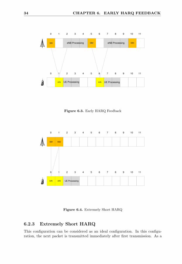
34 CHAPTER 6. EARLY HARQ FEEDBACK
0 1 2 3 4 5 6 7 8 9 10 11
SB1
A/N
0 1 2 3 4 5 6 7 8 9 10 11
SB2eNB Processing
A/N
eNB Processing SB3
UE Processing UE Processing
Figure 6.3. Early HARQ Feedback
0 1 2 3 4 5 6 7 8 9 10 11
SB1
A/N
0 1 2 3 4 5 6 7 8 9 10 11
SB2
A/N UE Processing
Figure 6.4. Extremely Short HARQ
6.2.3 Extremely Short HARQThis configuration can be considered as an ideal configuration. In this configu-ration, the next packet is transmitted immediately after first transmission. As a

6.2. CONFIGURATIONS FOR SIMULATIONS 35
result of fast transmissions in this case, the RTT is reduced. The UE processingtime remains at 4ms while the eNB processing is ignored. Figure 6.4 shows theExtremely Short HARQ feedback configuration.

Chapter 7
Algorithms andImplementation
In order to increase the efficiency of the HARQ protocol, some algorithms aresuggested in [2]. The algorithms include a new control message Early HARQFeedback that is sent earlier than the conventional HARQ feedback. This chapterwill describe some of the algorithms that have been implemented in the RadioNetwork Simulator during the project.
7.1 Early HARQ Feedback AlgorithmIn conventional HARQ, the receiver decodes the packet and sends the feedback tothe transmitter. The error results in 8ms of delay for each retransmission. In orderto efficiently perform link adaptation and reducing long packet delays, the receiverperforms early estimation about the consequence of the decoding attempt. Theestimated result is transmitted in the form a control message called Early HARQFeedback.
7.1.1 Early HARQ Feedback PropertiesFollowing are the properties of Early HARQ Feedback control message [2]:
• The EHF is transmitted at a time instant earlier than conventional HARQFeedback.
• The EHF can be positive or negative similar to conventional HARQ ACKand NACK respectively.
• The EHF is positive for excellent channel conditions and vice versa.
• The EHF can be incorrect and not match the conventional HARQ Feedback.
37

38 CHAPTER 7. ALGORITHMS AND IMPLEMENTATION
7.1.2 EHF Operation in DownlinkThe Feedback for a transmission in conventional HARQ is transmitted 4 sub-frames after reception. The EHF control message is transmitted at some earliertime instant. The transmission can be performed with 1, 2 or 3 subframes delayafter reception [2].
Extract MCS
from
Control Information
SNR from
BLER target
UE Receiver
Performance+
Error Margin
Required SINR
Received Signal
Power
Received Interference
Power
Estimated SINR
CalculationEstimated SINR
Early HARQ Feedback
Figure 7.1. Early HARQ Feedback Method for UE
As mentioned in section 7.1.1, the EHF can have either positive or negative value.In case of a negative value, retransmission will take place. In other case, theconventional HARQ feedback will decide for retransmission.
UE Procedure for EHF
The UE can calculate the EHF in a number of ways. Following are the suggestedways of generating the EHF in [2]:
• The first method to generate the EHF is to compare the estimated SINRwith the required SINR for high probability of successful decoding. If therequired SINR is greater than the expected SINR, the EHF has a negativevalue and vice versa. The required SINR can be generated from the bit errorprobability expressions for modulation schemes used in LTE. The estimatedSINR can be calculated from channel impulse response, signal power andnoise power.
• The second method is to do partial decoding of the received informationblock. Since, the turbo decoder uses a number of iterations to decode the

7.2. IMPLEMENTATION 39
packet, it is possible to utilize a few iterations of the decoder and calculateEHF on the basis of that value.
eNodeB Procedure for EHF
The eNB will receive the Early HARQ Feedback and perform the required steps.An immediate retransmission will take place in case of a negative EHF. If there arehigh priority transmissions, then the corrupted block will be transmitted at someother time. On the other hand, if the EHF is positive, the conventional HARQwill decide for retransmission or not [2].
Receive
Early HARQ Feeback
Send Information to
Higher Layers
Request for
Retransmission
Positive Negative
High Priority
Transmissions
Postpone
Retransmission
No Yes
Figure 7.2. Early HARQ Feedback Method for eNB
7.2 ImplementationThe implementation of EHF into the radio network simulator enironment has notbeen done according to 7.1.2. A more fundamental approach has been taken sincethe simulator lacks the support for a full implementation. The implementationhas been done in two steps as described below:
• The performance of EHF was assessed in the first step. The task has beenachieved by performing simulations under different simulation scenarios. Inthese simulations, EHF was equal to the conventional HARQ feedback andis, therefore, error free.

40 CHAPTER 7. ALGORITHMS AND IMPLEMENTATION
• In the second step, an implementation of an algorithm for generation of EHFhas been performed in the network simulator. The algorithm was similar tothe method used for comparing required SINR with expected SINR.
Figure 7.1 and Figure 7.2 shows the procedure for evaluating Early HARQ Feed-back at UE and eNB respectively.

Chapter 8
Simulation Scenarios
The Network simulator developed in Java is used to assess the impact on systemperformance with introduction of EHF. The network simulator is designed formodeling the radio network, protocol chain and the transport network in multi-cellsimulations for different radio access technologies. Additionally, it is possible toreconfigure the simulator structure and set the parameters to model the differentscenarios. The simulation environment used to assess the performance is generallybased on 3GPP specifications.
The models used consists of macro cell physical layer, the traffic modelsand higher layer configurations. The following sections show the details of thesettings of these models that have been used for performance measurement.
8.1 Macro Cell Model
3GPP case 1 deployment scenarios are assumed as default macro cell baselineparameters. Since the simulation environment is homogeneous network (macrocell), an extra 20 dB gain added to the distance dependent path loss (L) tocompensate the penetration loss (caused by indoor propagation). In addition tothat, ideal interference measurement is used in the simulator. That means thatthe UE measures interference on the data channel instead on the reference symbols.
2D antenna model and typical urban (TU) propagation model are used.Since the iterations takes 40 seconds, simple antenna and channel models areused in simulations to decrease the total simulation time.
Table 8.1 provides some details about parameters used on macro level.
41
42 CHAPTER 8. SIMULATION SCENARIOS
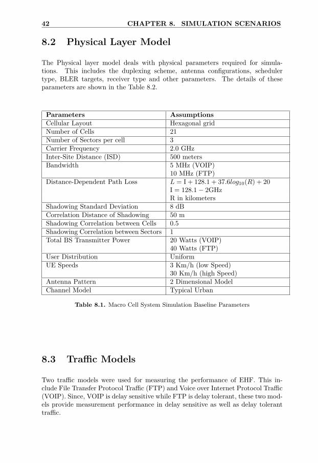
8.2 Physical Layer Model
The Physical layer model deals with physical parameters required for simula-tions. This includes the duplexing scheme, antenna configurations, schedulertype, BLER targets, receiver type and other parameters. The details of theseparameters are shown in the Table 8.2.
Parameters AssumptionsCellular Layout Hexagonal gridNumber of Cells 21Number of Sectors per cell 3Carrier Frequency 2.0 GHzInter-Site Distance (ISD) 500 metersBandwidth 5 MHz (VOIP)
10 MHz (FTP)Distance-Dependent Path Loss L = I + 128.1 + 37.6log10(R) + 20
I = 128.1 − 2GHzR in kilometers
Shadowing Standard Deviation 8 dBCorrelation Distance of Shadowing 50 mShadowing Correlation between Cells 0.5Shadowing Correlation between Sectors 1Total BS Transmitter Power 20 Watts (VOIP)
40 Watts (FTP)User Distribution UniformUE Speeds 3 Km/h (low Speed)
30 Km/h (high Speed)Antenna Pattern 2 Dimensional ModelChannel Model Typical Urban
Table 8.1. Macro Cell System Simulation Baseline Parameters
8.3 Traffic Models
Two traffic models were used for measuring the performance of EHF. This in-clude File Transfer Protocol Traffic (FTP) and Voice over Internet Protocol Traffic(VOIP). Since, VOIP is delay sensitive while FTP is delay tolerant, these two mod-els provide measurement performance in delay sensitive as well as delay toleranttraffic.

8.3. TRAFFIC MODELS 43
Parameters ValueDuplex Method Frequency Division DuplexingDownlink Transmission Scheme 2 × 2 MIMO Closed Loop MultiplexingDownlink Scheduling Round Robin for FTP
Delay Scheduler for VOIPMaximum Number of Scheduling 6 for PDCCHMessages 6 for PUCCHDownlink Link Adaptation Wideband CQI
Wideband PMI only for PUCCHCSI Feedback Error Neglected (No Feedback Error on PDCCH)HARQ Feedback Error NeglectedBLER Thresholds 10%
30%Downlink Receiver Type SIRC
Table 8.2. Physical Layer Framework
8.3.1 File Transfer ProtocolThe FTP is used for modeling delay tolerant traffic. Table 8.3 gives the detailsabout the parameters that have been used.
The reason for using two file sizes is in order to see the effects of smalland large data size. The log start time is used for skipping the transition phasebefore converging to a stable value.
Parameters ValueModel Applied to DownlinkNumber of Users in Simulation FixedReading Time, D Exponential Distribution, Mean 5sec
PDF: fD = λe−λD, D ≥ 0, λ = 0.2File Size 0.05MB, 0.5 MBNumber of Seed 10 Seeds for 21 users
1 Seed for 105, 210, 630, 1050 usersSimulation Time 40 secLog Start Time 2 sec
Table 8.3. File Transfer Protocol Parameters
8.3.2 Voice Over Internet ProtocolUnlike full buffer traffic (e.g. file download) which is typically delay-tolerant anddoes not guarantee a constant bit-rate, a real time traffic model such as VOIP hastight delay constraints. Hence the system capacity requirements must be clearly

44 CHAPTER 8. SIMULATION SCENARIOS
set for such services. VOIP system parameters and configurations are specified inTable 8.4.
Parameters ValueAverage Number of Users per Cell 25, 50, 100, 140, 160, 180, 200, 220, 250,
280, 310Number of PDCCH Grants 50 (Unlimited Case)Downlink Link Adaptation Normal, Aggressive100Simulation Time 65.5 secLog start 2 sec
Table 8.4. Voice Over Internet Protocol Parameters
8.4 Higher Layer ConfigurationThere are other configurations except those explained in previous sections. Thisinclude the configuration of higher layers of which the HARQ configurations aremost important. Table 8.5 shows the configuration parameters for higher layers.The HARQ Feedback Evaluation with 2ms is called Extremely Short HARQ whileHARQ Feedback Evaluation with 5ms is called Early HARQ Feedback.
Parameters ValueTransport Network Delay to 5 msInternet Delay 4 msHARQ Feedback Transmission 1 msHARQ Feedback Evaluation 2 ms, 5 ms
Table 8.5. Higher Layer Configurations

Chapter 9
Results
This chapter will describe the results for FTP and VOIP scenarios for differentHARQ configurations and the conclusions drawn from the work. In the end, thechapter will discuss possible future enhancements of the algorithms.
9.1 Performance Measures9.1.1 File Transfer ProtocolTo evaluate the system performance for FTP traffic model, two important mea-sures will be discussed; cell throughput gain and average packet bit rate gain.
• Average bit rate means the average number of bits transferred to a user perunit of time. Usually, average bit rate is measured in bits/s.
• Cell throughput refers to the rate at which the eNB successfully transmitsbits over a radio channel.
When all of the simulation log files are collected, the post processing has to becompleted afterwards. Consequently, the post processing creates figures (averagepacket bit rate vs. cell throughput) to compare different configurations. Thoseconfigurations are dominantly affected by different type of network loads, trafficmodels and HARQ processes.
Resource block utilization (subband utilization) is also an important mea-sure to assess the system performance. It refers to the amount of resourcesutilized during any time instant. It is required to have a low resource utilizationin designing an algorithm. This will help in utilization of remaining resources forother transmissions. By using outer loop algorithms, aggressive link adaptationwill be introduced to ensure several transmission attempts which can give anincrease in transmission delays when utilizing the conventional HARQ. WithEHF, the delay from having retransmissions becomes smaller. So, aggressive LAcan be utilized and resource block utilization becomes better.
45

46 CHAPTER 9. RESULTS
9.1.2 Voice Over Internet ProtocolFor VOIP capacity evaluations, the following performance metrics need to beconsidered:
• System capacity is defined as the number of users in the cell when more than[95%] of the users are satisfied.
• A VOIP user is in outage (not satisfied) if [98%] radio interface tail latencyof the user is greater than [50 ms]. This assumes an end-to-end delay below[200 ms] for mobile-to-mobile communications in LTE.
In addition to above requirements, HARQ RTT also affects the system capacityfor delay sensitive services like VOIP. As mentioned in Section 6.1.1, in 3GPPrelease 8, the VOIP delay bound is 50 ms for a user and LTE HARQ RTT is 8ms, it means that up to 6 transmissions per voice packet is possible. In this way,system capacity is positively affected when EHF is introduced which reduces theHARQ RTT and increases the number of possible retransmissions. Finally, theeffects of different HARQ schemes in VOIP traffic model will be discussed in thenext chapter.
The downlink control channel capacity is an important parameter to ana-lyze the system performance for VOIP case. The point to use unlimited downlinkcontrol channel capacity is to reduce the retransmission costs on the controlchannel. Aggressive LA and fast packet retransmissions introduce a high numberof retransmissions which requires a high number of control channel resources.So, due to limited downlink control channel resources, it is infeasible to expectreasonable capacity gain. Moreover, if we have a low number of available grants,the VOIP capacity is expected to be limited by the number of grants. This meansthat reducing the downlink data channel resource utilization will not result in aVOIP capacity gain. So, in case of a grant limited scenario, we cannot expect anygains from having a more aggressive LA.
9.2 Simulation Results9.2.1 File Transfer ProtocolFigure 9.1 to Figure 9.8 shows the results for small file size while Figure 9.9to 9.16 will show the results for large file size. For each scenario, we presentgraphs showing the average bit rate as a function of cell throughput and graphsshowing the sub band utilization. The Extreme HARQ in the figures refers to theExtremely Short HARQ configuration.
Figure 9.1 shows the comparison among various HARQ configurations with lowspeed. The figure shows a gain of 11% with Extremely Short HARQ schemecompared to conventional HARQ configuration in both low and high loadconditions. In the low speed scenario, the resource utilization is the same for

9.2. SIMULATION RESULTS 47
0 1 2 3 4 5 6 7 8
x 106
900
1000
1100
1200
1300
1400
1500
1600
1700
1800
1900
Cell Throughput (bits/s)
Ave
rage
pac
ket b
it ra
te (
bits
/s)
Conventional HARQ, BLER 10%, low Speed
Conventional HARQ, BLER 30%, low Speed
Early HARQ, BLER 10%, low Speed
Extreme HARQ, BLER 10%, low Speed
Figure 9.1. Cell Throughput and Average Bit Rate with small file size
0 1 2 3 4 5 6 7 8
x 106
0%
10%
20%
30%
40%
50%
60%
70%
80%
90%
100%
Cell Throughput (bits/s)
Dow
nlin
k S
ubba
nd U
tiliz
atio
n
Conventional HARQ, BLER 10%, low Speed
Conventional HARQ, BLER 30%, low Speed
Early HARQ, BLER 10%, low Speed
Extreme HARQ, BLER 10%, low Speed
Figure 9.2. Subband Utilization with small file size (low speed)
normal and aggressive LA as shown in Figure 9.2 and the gain comes from thedecrease in round trip time. Moreover, in low speed scenario, the CQI reports areaccurate which makes 10% BLER target a good choice. With more aggressive
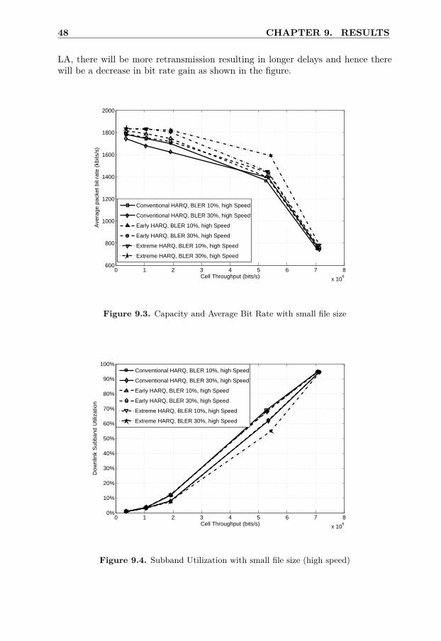
48 CHAPTER 9. RESULTS
LA, there will be more retransmission resulting in longer delays and hence therewill be a decrease in bit rate gain as shown in the figure.
0 1 2 3 4 5 6 7 8
x 106
600
800
1000
1200
1400
1600
1800
2000
Cell Throughput (bits/s)
Ave
rage
pac
ket b
it ra
te (
kbits
/s)
Conventional HARQ, BLER 10%, high Speed
Conventional HARQ, BLER 30%, high Speed
Early HARQ, BLER 10%, high Speed
Early HARQ, BLER 30%, high Speed
Extreme HARQ, BLER 10%, high Speed
Extreme HARQ, BLER 30%, high Speed
Figure 9.3. Capacity and Average Bit Rate with small file size
0 1 2 3 4 5 6 7 8
x 106
0%
10%
20%
30%
40%
50%
60%
70%
80%
90%
100%
Cell Throughput (bits/s)
Dow
nlin
k S
ubba
nd U
tiliz
atio
n
Conventional HARQ, BLER 10%, high Speed
Conventional HARQ, BLER 30%, high Speed
Early HARQ, BLER 10%, high Speed
Early HARQ, BLER 30%, high Speed
Extreme HARQ, BLER 10%, high Speed
Extreme HARQ, BLER 30%, high Speed
Figure 9.4. Subband Utilization with small file size (high speed)

9.2. SIMULATION RESULTS 49
Figure 9.3 shows the comparison for high speed configurations. In low load condi-tions, the Extremely Short HARQ shows a gain of 6% while Early HARQ showsa gain of 3% compared to conventional HARQ configuration (Link Adaptationwith 10% BLER target). The high speed scenario does not affect the systemgain at low load conditions and the aggressive LA does not enhance the gain.At high load conditions, the gain experienced with Extremely Short HARQ is8% in comparison to conventional HARQ configuration. An interesting resultis that Early HARQ Feedback has higher gain in high load conditions thanExtremely Short HARQ with aggressive LA. This is due to the fact that resourceutilization becomes an important factor. With more aggressive LA, a smallernumber of resources is utilized than for normal link adaptation and freed upresources can be used for other transmissions. This can be verified from Figure 9.4.
In Figure 9.3, it is concluded that the gain at high load conditions can beincreased with a more aggressive LA scheme. In order to achieve that, the firsttransmission occurs with block error rate of approximately 100% while the secondtransmission goes for a 10% block error rate. Figure 9.5 shows the result withthis method. In low load conditions, the gain of Extremely Short HARQ is 8%in comparison to conventional HARQ configuration. At high load conditions,the gain experienced with Extremely Short HARQ is 20% in comparison withconventional HARQ.
0 1 2 3 4 5 6 7 8
x 106
600
800
1000
1200
1400
1600
1800
2000
Cell Throughput (bits/s)
Ave
rage
pac
ket b
it ra
te (
kbits
/s)
Conventional HARQ, BLER 10, high Speed, attempt 2
Early HARQ, BLER 10, high Speed, attempt 2
Extreme HARQ, BLER 10, high Speed, attempt 2
Conventional HARQ, BLER 10%, high Speed
Figure 9.5. Capacity and Average Bit Rate with small file size
In order to achieve higher gains, an even more aggressive LA scheme can be used.This can be achieved by using the highest MCS value for the first transmission in

50 CHAPTER 9. RESULTS
0 1 2 3 4 5 6 7 8
x 106
0%
10%
20%
30%
40%
50%
60%
70%
80%
90%
100%
Cell Throughput (bits/s)
Dow
nlin
k S
ubba
nd U
tiliz
atio
n
Conventional HARQ, BLER 10%, high Speed, attempt 2
Early HARQ, BLER 10%, high Speed, attempt 2
Extreme HARQ, BLER 10%, high Speed, attempt 2
Conventional HARQ, BLER 10%, high Speed
Figure 9.6. Subband Utilization with small file size (Aggressive LA)
0 1 2 3 4 5 6 7 8
x 106
200
400
600
800
1000
1200
1400
1600
1800
2000
Cell Throughput (bits/s)
Ave
rage
pac
ket b
it ra
te (
kbits
/s)
conventional normal LAconventional aggressive LAEHF normal LAEHF aggressive LAextreme normal LAextreme aggressive LA
Figure 9.7. Capacity and Average Bit Rate with small file size
order to ensure a second transmission. Figure 9.7 shows the comparison betweendifferent HARQ configurations with fixed MCS value. As can be seen in Figure9.7, the gains in high load conditions in comparison with conventional HARQ

9.2. SIMULATION RESULTS 51
0 1 2 3 4 5 6 7 8
x 106
0%
10%
20%
30%
40%
50%
60%
70%
80%
90%
100%
Cell Throughput (bits/s)
Dow
nlin
k S
ubba
nd U
tiliz
atio
n
Conventional normal LA
Conventional aggressive LA
EHF normal LA
EHF aggressive LA
extreme normal LA
extreme aggressive LA
Figure 9.8. Subband Utilization with small file size (fixed MCS)
3 4 5 6 7 8 9 10 11 12
x 106
0
1000
2000
3000
4000
5000
6000
7000
8000
Cell Throughput (bits/s)
Ave
rage
pac
ket b
it ra
te (
kbits
/s)
Conventional HARQ, BLER 10%, low SpeedConventional HARQ, BLER 30%, low SpeedEarly HARQ, BLER 10%, low SpeedExtreme HARQ, BLER 10%, low Speed
Figure 9.9. Capacity and Average Bit Rate with large file size
configuration decreased. A fixed high value of MCS (which is only done for thefirst transmission) will cause a failed initial transmission for each user. As aresult, there will be a decrease in bit rate gain. The important result deduced

52 CHAPTER 9. RESULTS
3 4 5 6 7 8 9 10 11 12
x 106
0%
10%
20%
30%
40%
50%
60%
70%
80%
90%
100%
Cell Throughput (bits/s)
Dow
nlin
k S
ubba
nd U
tiliz
atio
n
Conventional HARQ, BLER 10%, low SpeedConventional HARQ, BLER 30%, low SpeedEarly HARQ, BLER 10%, low SpeedExtreme HARQ, BLER 10%, low Speed
Figure 9.10. Subband Utilization with large file size (low speed)
3 4 5 6 7 8 9 10 11
x 106
0
1000
2000
3000
4000
5000
6000
7000
8000
Cell Throughput (bits/s)
Ave
rage
pac
ket b
it ra
te (
kbits
/s)
Conventional HARQ, BLER 10%, high SpeedConventional HARQ, BLER 30%, high SpeedEarly HARQ, BLER 10%, high SpeedEarly HARQ, BLER 30%, high SpeedExtreme HARQ, BLER 10%, high SpeedExtreme HARQ, BLER 30%, high Speed
Figure 9.11. Capacity and Average Bit Rate with large file size
from the figure is that there is a gain of 204% when comparing the ExtremelyShort HARQ configuration with conventional HARQ configuration at 5 Mbps cellthroughput.

9.2. SIMULATION RESULTS 53
3 4 5 6 7 8 9 10 11
x 106
0%
10%
20%
30%
40%
50%
60%
70%
80%
90%
100%
Cell Throughput (bits/s)
Dow
nlin
k S
ubba
nd U
tiliz
atio
n
Conventional HARQ, BLER 10%, high Speed
Conventional HARQ, BLER 30%, high Speed
Early HARQ, BLER 10%, high Speed
Early HARQ, BLER 30%, high Speed
Extreme HARQ, BLER 10%, high Speed
Extreme HARQ, BLER 30%, high Speed
Figure 9.12. Subband Utilization with large file size (high speed)
2 3 4 5 6 7 8 9 10 11 12
x 106
0
1000
2000
3000
4000
5000
6000
7000
8000
Cell Throughput (bits/s)
Ave
rage
pac
ket b
it ra
te (
kbits
/s)
Conventional HARQ, BLER 10, attempt 2Early HARQ, BLER 10, attempt 2Extreme HARQ, BLER 10, attempt 2Conventional HARQ, BLER 30%, low Speed
Figure 9.13. Capacity and Average Bit Rate with large file size
The FTP results also shows that the gain in conventional HARQ by usingaggressive LA decreased in spite of normal LA at low loads. The reason is due tohigh number of retransmissions and long delays. This does not apply for EHF. In

54 CHAPTER 9. RESULTS
2 3 4 5 6 7 8 9 10 11
x 106
0%
10%
20%
30%
40%
50%
60%
70%
80%
90%
100%
Cell Throughput (bits/s)
Dow
nlin
k S
ubba
nd U
tiliz
atio
n
Conventional HARQ, BLER 10%, high Speed, attempt 2
Early HARQ, BLER 10%, high Speed, attempt 2
Extreme HARQ, BLER 10%, high Speed, attempt 2
Conventional HARQ, BLER 10%, high Speed
Figure 9.14. Subband Utilization with large file size (Aggressive LA)
2 3 4 5 6 7 8 9 10 11
x 106
0
1000
2000
3000
4000
5000
6000
7000
8000
Cell Throughput (bits/s)
Ave
rage
pac
ket b
it ra
te (
kbits
/s)
conventional normal LA
conventional aggressive LA
EHF normal LA
EHF aggressive LA
extreme aggressive LA
Figure 9.15. Capacity and Average Bit Rate with large file size
EHF, there is a gain in comparison to conventional HARQ and robust LA at allloads.

9.2. SIMULATION RESULTS 55
2 3 4 5 6 7 8 9 10 11
x 106
0%
10%
20%
30%
40%
50%
60%
70%
80%
90%
100%
Cell Throughput (bits/s)
Dow
nlin
k S
ubba
nd U
tiliz
atio
n
Conventional normal LA
Conventional aggressive LA
Early normal LA
Early aggressive LA
Extreme normal LA
Extreme aggressive LA
Figure 9.16. Subband Utilization with large file size (fixed MCS)
A small investigation has been performed to study the errors expected from EarlyHARQ Feedback algorithms. These errors are the difference between the feedbackcalculated from conventional HARQ and Early HARQ Feedback algorithms. Thesimulations were performed in the aggressive LA environment. The errors werefound to be 40-45%. The errors occur due to the fact that conventional HARQalgorithm is used along with combining methods and utilize earlier receptionsto perform decoding. In the performed simulations, the Early HARQ Feedbackis used as a standalone algorithm and depends only on current value of theestimated SINR. Moreover, most of the errors with early HARQ feedback areNACK to ACK errors. This means that EHF feedback is an ACK instead of aNACK. If conventional HARQ generates feedback as a NACK, the packet will belost since no data is transmitted to higher layers and no HARQ retransmissionis performed since an ACK is signaled. For Early HARQ Feedback, the packetwill be retransmitted for NACK feedback. In this case, the packet will not betransmitted to higher layers and request for retransmission will be made. Due toretransmission, only the RTT will increase and hence, there will be a decrease ingain. If the errors are ACK to NACK errors (EHF feedback is NACK instead ofan ACK), the packet will be transmitted to higher layers after UE processing.This means that transmission is correctly received. So, EHF should have beenACK. In short, the ACK to NACK errors result in extra retransmissions andhigher resource utilization.
The results of FTP with large file size are shown in Figure 9.9 to 9.16

56 CHAPTER 9. RESULTS
which show smaller gains than the results obtained from small file size. Thedecrease in gain is due to the need for a small amount of download time in TCPslow start. In TCP slow start, the TCP congestion window is increased each timean acknowledgement is received. If a NACK is received, TCP assumes it to bedue to network congestion and enters into a linear growth phase. This is alsotrue when maximum congestion window size is reached. In case of large file size,a large amount of time is required for file transfer. Therefore, FTP for large filesize is similar to the full buffer scenario. As a result, reduced feedback time givesno gain.
9.2.2 Voice Over Internet Protocol
0 1000 2000 3000 4000 5000 6000 700050%
60%
70%
80%
90%
100%
Number of Users
Sat
isfie
d U
sers
conventional HARQ, normal LA
EHF, normal LA
extreme HARQ, normal LA
conventional HARQ, aggressive LA
EHF, aggressive LA
extreme HARQ, aggressive LA
Figure 9.17. Satisfied Users, 80ms Air Interface Delay
The percentage of satisfied users for different number of users are shown in Figure9.17 and 9.18. The only difference between the two figures is that the maximumair interface delay is assumed to be 80ms and 50 ms respectively. As discussedearlier in the VOIP capacity evaluations, the air interface delay shouldn’t exceed50 ms or 80 ms. Extreme short HARQ and EHF give slightly better results in50ms delay where there is no big difference between HARQ schemes. On the otherhand aggressive LA increases the number of satisfied users with 17% capacity gainwhen 95% of users are satisfied. In Figure 9.18, it is possible too see different gainsbetween different HARQ schemes whereas that is not the case for the 80 ms delaycase Figure 9.17. That is an expected result because in the 80 ms delay case, it ispossible to use a high number of retransmissions where in the 50 ms delay case,the number of retransmissions is more limited. Therefore, small HARQ RTT is an

9.2. SIMULATION RESULTS 57
0 1000 2000 3000 4000 5000 6000 700030%
40%
50%
60%
70%
80%
90%
100%
Number of Users
Sat
isfie
d U
sers
conventional HARQ, normal LA
conventonal HARQ, aggressive LA
EHF, normal LA
EHF, aggressive LA
extreme HARQ, normal LA
extreme HARQ, aggressive LA
Figure 9.18. Satisfied Users, 50ms Air Interface Delay
important aspect in delay sensitive communications.
0 1000 2000 3000 4000 5000 6000 70000
50
100
150
200
250
300
350
400
450
Number of Users
Use
r D
elay
Per
cent
ile [m
s]
conventional HARQ, normal LA
conventional HARQ, aggressive LA
EHF, normal LA
EHF, aggressive LA
extreme HARQ, normal LA
extreme HARQ, aggressive LA
Figure 9.19. User Delay Percentile
Figure 9.19 displays the user delay experience under different network loads.

58 CHAPTER 9. RESULTS
The most important point is that aggressive LA has a greater impact on delaysthan different HARQ schemes. If aggressive LA is introduced instead of normalLA the delays can significantly be reduced at high load (even more than 100%).Since the channel is not stable at high load (e.g. high interference) aggressive LAcan correct the channel estimation errors and the delay experience is minimized.Moreover there are many unsatisfied users at high load where 50ms is thethreshold value for successful transmissions. (This can also be observed in Figure9.17 and 9.18.) Within 50 ms region, extreme HARQ and EHF show better re-sults at high load. The gain is almost 15 ms which gives a system capacity increase.
Figure 9.20 is related to HARQ NACK rate with respect to different net-work loads. In the simulations it is assumed that the HARQ feedback error iszero for all HARQ configurations thus aggressive LA determines the NACK rate.When some of EHF methods are implemented the HARQ schemes will not workideally which affects the system. However, from this figure it can be said thatthe BLER target converges to 30% in aggressive LA and 10% in normal LA.Basically, the figure only shows how aggressive LA affects the transmission.
Downlink PDCCH utilization graphs are given in Figure 9.21, 9.22 and9.23 by looking at the average, best (95% - ile) and worst (5% - ile) userperformance. Aggressive LA has better utilization at high load which is anexpected result. Same results can be seen in subband (PDSCH) utilization whichis drawn in Figure 9.24 and 9.25 where all the resources are fully used in best andworst user scenarios.
0 1000 2000 3000 4000 5000 6000 70000%
5%
10%
15%
20%
25%
30%
Number of Users
HA
RQ
NA
CK
Rat
e
conventional HARQ, normal LA
conventional HARQ, aggressive LA
EHF, normal LA
EHF, aggressive LA
extreme HARQ, normal LA
extreme HARQ, aggressive LA
Figure 9.20. HARQ NACK Rate

9.3. CONCLUSION 59
0 1000 2000 3000 4000 5000 6000 70000
2
4
6
8
10
12
Number of Users
Dow
nlin
k A
ssig
nmen
ts (
PD
CC
H)
Util
izat
ion
conventional HARQ, normal LA
conventional HARQ, aggressive LA
EHF, normal LA
EHF, aggressive LA
extreme HARQ, normal LA
extreme HARQ, aggressive LA
Figure 9.21. Downlink PDCCH Utilization-Average
0 1000 2000 3000 4000 5000 6000 70002
4
6
8
10
12
14
Number of Users
Dow
nlin
k A
ssig
nmen
ts (
PD
CC
H)
Util
izat
ion
conventional HARQ, normal LA
conventional HARQ, aggressive LA
EHF, normal LA
EHF, aggressive LA
extreme HARQ, normal LA
extreme HARQ, aggressive LA
Figure 9.22. Downlink PDCCH Utilization-95%-ile
9.3 ConclusionThe thesis work shows that reducing the HARQ RTT significantly affects systemperformance when the number of retransmissions are increased by using a more

60 CHAPTER 9. RESULTS
0 1000 2000 3000 4000 5000 6000 70000
1
2
3
4
5
6
Number of Users
Dow
nlin
k A
ssig
nmen
ts (
PD
CC
H)
Util
izat
ion
conventional HARQ, normal LA
conventional HARQ, aggressive LA
EHF, normal LA
EHF, aggressive LA
extreme HARQ, normal LA
extreme HARQ, aggressive LA
Figure 9.23. Downlink PDCCH Utilization-5%-ile
0 1000 2000 3000 4000 5000 6000 70000%
10%
20%
30%
40%
50%
60%
70%
80%
90%
100%
Number of Users
Dow
nlin
k S
ubba
nd (
PD
SC
H)
Util
izat
ion
conventional HARQ, normal LA
conventional HARQ, aggressive LA
EHF, normal LA
EHF, aggressive LA
extreme HARQ, normal LA
extreme HARQ, aggressive LA
Figure 9.24. Downlink PDSCH Utilization-Average
aggressive LA. However the crucial point is to find a suitable communication en-vironment to see the potential of the idea. In this way, traffic models were the
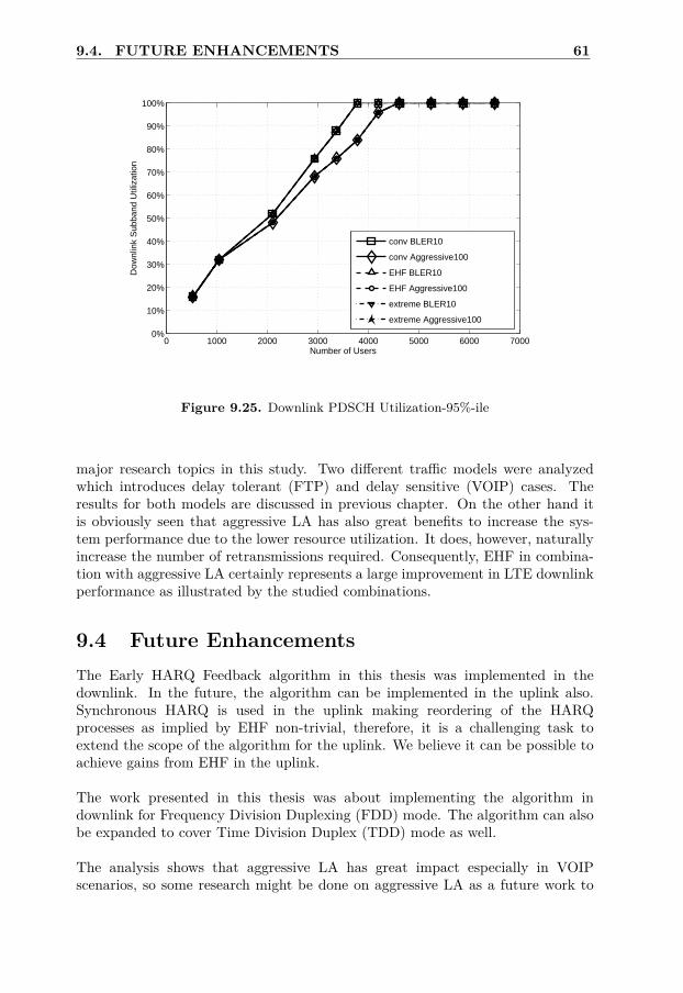
9.4. FUTURE ENHANCEMENTS 61
0 1000 2000 3000 4000 5000 6000 70000%
10%
20%
30%
40%
50%
60%
70%
80%
90%
100%
Number of Users
Dow
nlin
k S
ubba
nd U
tiliz
atio
n
conv BLER10
conv Aggressive100
EHF BLER10
EHF Aggressive100
extreme BLER10
extreme Aggressive100
Figure 9.25. Downlink PDSCH Utilization-95%-ile
major research topics in this study. Two different traffic models were analyzedwhich introduces delay tolerant (FTP) and delay sensitive (VOIP) cases. Theresults for both models are discussed in previous chapter. On the other hand itis obviously seen that aggressive LA has also great benefits to increase the sys-tem performance due to the lower resource utilization. It does, however, naturallyincrease the number of retransmissions required. Consequently, EHF in combina-tion with aggressive LA certainly represents a large improvement in LTE downlinkperformance as illustrated by the studied combinations.
9.4 Future EnhancementsThe Early HARQ Feedback algorithm in this thesis was implemented in thedownlink. In the future, the algorithm can be implemented in the uplink also.Synchronous HARQ is used in the uplink making reordering of the HARQprocesses as implied by EHF non-trivial, therefore, it is a challenging task toextend the scope of the algorithm for the uplink. We believe it can be possible toachieve gains from EHF in the uplink.
The work presented in this thesis was about implementing the algorithm indownlink for Frequency Division Duplexing (FDD) mode. The algorithm can alsobe expanded to cover Time Division Duplex (TDD) mode as well.
The analysis shows that aggressive LA has great impact especially in VOIPscenarios, so some research might be done on aggressive LA as a future work to

62 CHAPTER 9. RESULTS
further investigate its potential benefits. In this thesis work, aggressive100 is usedin VOIP due to its good performance. It might be a good idea to specify BLERtarget for more than two transmissions. Aggressive100 has 100% BLER targetfor the first transmission and 10% BLER target for the second transmission. Itmight be good if also a third transmission is taken into account. For instance, thefirst and second transmissions can be set to higher BLER targets to see whetherit has a higher gain or not. This way, it is possible to get even more aggressiveLA, which might give interesting results at high load.
The HARQ Feedback error is assumed to be zero in this study which means thatperfect EHF schemes are used in the simulations. Thus more investigation needsto be done on how to implement EHF and what performance can be reached withnon-perfect EHF.
Some users are limited by the highest MCS, i-e, they will never get morethan one transmission attempt with the current TBS table in 3GPP standards. Itcould be interesting to investigate the performance of EHF when the current TBStable is extended. Hereby more transmission attempts are allowed for all users.

Bibliography
[1] Erik Eriksson. Link Adaptation in LTE Uplink: Final Report. Internal Docu-ment, Ericsson AB.
[2] Niclas Wiberg. Early HARQ Feedback for Efficient Link Adaptation: InternalDocument, Ericsson AB. 2009.
[3] Stefania Sesia, Issam Toufik, Matthew Baker. LTEThe UMTS Long Term Evo-lution: From Theory to Practice. John Wiley & Sons, 1st Edition, 2009. ISBN:978-0-470-69716-0.
[4] Farooq Khan. LTE for 4G Mobile Broadband. Cambridge University Press.2009. ISBN: 978-0-511-51666-5.
[5] Erik Dahlman, Stefan Parkvall, Johan Sköld, Per Beming. 3G Evolution:HSPA and LTE for Mobile Broadband. Academic Press. 2007. ISBN: 978-0-123-72533-2.
[6] Erik Dahlman, Stefan Parkvall, Johan Sköld. 4G LTE/LTE-Advanced for Mo-bile Broadband. Academic Press. 2011. ISBN: 978-0-123-85489-6.
63


![Long Term Evolution and Enhanced Packet Core (LTE and EPC ...ewh.ieee.org/r1/njcoast/LTE-ePCTalkOct24-2008[1].pdf · Long Term Evolution and Enhanced Packet Core (LTE and EPC) ...](https://static.fdocuments.net/doc/165x107/5a9753c27f8b9a9c5b8d2fc4/long-term-evolution-and-enhanced-packet-core-lte-and-epc-ewhieeeorgr1njcoastlte-epctalkoct24-20081pdflong.jpg)