Fast and Flexible Successive-Cancellation List Decoders ...
14
1 Fast and Flexible Successive-Cancellation List Decoders for Polar Codes Seyyed Ali Hashemi, Student Member, IEEE, Carlo Condo, Warren J. Gross, Senior Member, IEEE Abstract—Polar codes have gained significant amount of at- tention during the past few years and have been selected as a coding scheme for the next generation of mobile broad- band standard. Among decoding schemes, successive-cancellation list (SCL) decoding provides a reasonable trade-off between the error-correction performance and hardware implementation complexity when used to decode polar codes, at the cost of limited throughput. The simplified SCL (SSCL) and its extension SSCL-SPC increase the speed of decoding by removing redun- dant calculations when encountering particular information and frozen bit patterns (rate one and single parity check codes), while keeping the error-correction performance unaltered. In this paper, we improve SSCL and SSCL-SPC by proving that the list size imposes a specific number of path splitting required to decode rate one and single parity check codes. Thus, the number of splitting can be limited while guaranteeing exactly the same error-correction performance as if the paths were forked at each bit estimation. We call the new decoding algorithms Fast-SSCL and Fast-SSCL-SPC. Moreover, we show that the number of path forks in a practical application can be tuned to achieve desirable speed, while keeping the error-correction performance almost unchanged. Hardware architectures implementing both algorithms are then described and implemented: it is shown that our design can achieve 1.86 Gb/s throughput, higher than the best state-of-the-art decoders. Index Terms—polar codes, successive-cancellation decoding, list decoding, hardware implementation. I. I NTRODUCTION Polar codes are the first family of error-correcting codes with provable capacity-achieving property and a low-complexity encoding and decoding process [2]. The successive-cancellation (SC) decoding is a low-complexity algorithm with which polar codes can achieve the capacity of a memoryless channel. However, there are two main drawbacks associated with SC. Firstly, SC requires the decoding process to advance bit by bit. This results in high latency and low throughput when implemented in hardware [3]. Second, polar codes decoded with SC only achieve the channel capacity when the code length tends toward infinity. For practical polar codes of moderate length, SC falls short in providing a reasonable error-correction performance. The first issue is a result of the serial nature of SC. In order to address this issue, the recursive structure of polar codes construction and the location of information and parity (frozen) bits were utilized in [4], [5] to identify constituent This work has been published in parts in the IEEE Wireless Communica- tions and Networking Conference Workshops (WCNCW), 2017 [1]. S. A. Hashemi, C. Condo, and W. J. Gross are with the De- partment of Electrical and Computer Engineering, McGill Univer- sity, Montr´ eal, Qu´ ebec, Canada. e-mail: [email protected], [email protected], [email protected]. polar codes. In particular, rate zero (Rate-0) codes with all frozen bits, rate one (Rate-1) codes with all information bits, repetition (Rep) codes with a single information bit in the most reliable position, and single parity-check (SPC) codes with a single frozen bit in the least reliable position, were shown to be capable of being decoded in parallel with low-complexity decoding algorithms. This in turn increased the throughput and reduced the latency significantly. Moreover, the simplifications in [4], [5] did not introduce any error-correction performance degradation with respect to conventional SC. The second issue stems from the fact that SC is suboptimal with respect to maximum-likelihood (ML) decoding. The decoding of each bit is only dependent on the bits already decoded. SC is unable to use the information about the bits that are not decoded yet. In order to address this issue, SC list (SCL) decoding advances by estimating each bit as either 0 or 1. Therefore, the number of candidate codewords doubles at each bit estimation step. In order to limit the exponential increase in the number of candidates, only L candidate codewords are allowed to survive by employing a path metric (PM) [6]. The PMs were sorted and the L best candidates were kept for further processing. It should be noted that SCL was previously used to decoder Reed-Muller codes [7]. SCL reduces the gap between SC and ML and it was shown that when a cyclic redundancy check (CRC) code is concatenated with polar codes, SCL can make polar codes outperform the state-of-the-art codes to the extent that polar codes have been chosen to be adopted in the next generation of mobile broadband standard [8]. The good error-correction performance of SCL comes at the cost of higher latency, lower throughput, and higher area occupation than SC when implemented on hardware [9]. It was identified in [10] that using the log-likelihood ratio (LLR) values results in a SCL decoder which is more area-efficient than the conventional SCL decoder with log-likelihood (LL) values. In order to reduce the latency and increase the through- put associated with SCL, several attempts have been made to reduce the number of required decoding time steps as defined in [2]. It should be noted that different time steps might entail different operations (e.g. a bit estimation or an LLR value update), and might thus last a different number of clock cycles. A group of M bits were allowed to be decoded together in [11], [12]. [13] proposed a high throughput architecture based on a tree-pruning scheme and further extended it to a multimode decoder in [14]. The throughput increase in [13] is based on code-based parameters which could degrade the error- correction performance significantly. Based on the idea in [5], a fast list decoder architecture for software implementation arXiv:1703.08208v2 [cs.IT] 29 Aug 2017
Transcript of Fast and Flexible Successive-Cancellation List Decoders ...

1
Fast and Flexible Successive-Cancellation ListDecoders for Polar Codes
Seyyed Ali Hashemi, Student Member, IEEE, Carlo Condo, Warren J. Gross, Senior Member, IEEE
Abstract—Polar codes have gained significant amount of at-tention during the past few years and have been selected asa coding scheme for the next generation of mobile broad-band standard. Among decoding schemes, successive-cancellationlist (SCL) decoding provides a reasonable trade-off betweenthe error-correction performance and hardware implementationcomplexity when used to decode polar codes, at the cost oflimited throughput. The simplified SCL (SSCL) and its extensionSSCL-SPC increase the speed of decoding by removing redun-dant calculations when encountering particular information andfrozen bit patterns (rate one and single parity check codes),while keeping the error-correction performance unaltered. In thispaper, we improve SSCL and SSCL-SPC by proving that thelist size imposes a specific number of path splitting required todecode rate one and single parity check codes. Thus, the numberof splitting can be limited while guaranteeing exactly the sameerror-correction performance as if the paths were forked at eachbit estimation. We call the new decoding algorithms Fast-SSCLand Fast-SSCL-SPC. Moreover, we show that the number ofpath forks in a practical application can be tuned to achievedesirable speed, while keeping the error-correction performancealmost unchanged. Hardware architectures implementing bothalgorithms are then described and implemented: it is shown thatour design can achieve 1.86 Gb/s throughput, higher than thebest state-of-the-art decoders.
Index Terms—polar codes, successive-cancellation decoding,list decoding, hardware implementation.
I. INTRODUCTION
Polar codes are the first family of error-correctingcodes with provable capacity-achieving property and alow-complexity encoding and decoding process [2]. Thesuccessive-cancellation (SC) decoding is a low-complexityalgorithm with which polar codes can achieve the capacity of amemoryless channel. However, there are two main drawbacksassociated with SC. Firstly, SC requires the decoding processto advance bit by bit. This results in high latency and lowthroughput when implemented in hardware [3]. Second, polarcodes decoded with SC only achieve the channel capacitywhen the code length tends toward infinity. For practicalpolar codes of moderate length, SC falls short in providinga reasonable error-correction performance.
The first issue is a result of the serial nature of SC. Inorder to address this issue, the recursive structure of polarcodes construction and the location of information and parity(frozen) bits were utilized in [4], [5] to identify constituent
This work has been published in parts in the IEEE Wireless Communica-tions and Networking Conference Workshops (WCNCW), 2017 [1].
S. A. Hashemi, C. Condo, and W. J. Gross are with the De-partment of Electrical and Computer Engineering, McGill Univer-sity, Montreal, Quebec, Canada. e-mail: [email protected],[email protected], [email protected].
polar codes. In particular, rate zero (Rate-0) codes with allfrozen bits, rate one (Rate-1) codes with all information bits,repetition (Rep) codes with a single information bit in the mostreliable position, and single parity-check (SPC) codes with asingle frozen bit in the least reliable position, were shown tobe capable of being decoded in parallel with low-complexitydecoding algorithms. This in turn increased the throughput andreduced the latency significantly. Moreover, the simplificationsin [4], [5] did not introduce any error-correction performancedegradation with respect to conventional SC.
The second issue stems from the fact that SC is suboptimalwith respect to maximum-likelihood (ML) decoding. Thedecoding of each bit is only dependent on the bits alreadydecoded. SC is unable to use the information about the bitsthat are not decoded yet. In order to address this issue,SC list (SCL) decoding advances by estimating each bit aseither 0 or 1. Therefore, the number of candidate codewordsdoubles at each bit estimation step. In order to limit theexponential increase in the number of candidates, only Lcandidate codewords are allowed to survive by employing apath metric (PM) [6]. The PMs were sorted and the L bestcandidates were kept for further processing. It should be notedthat SCL was previously used to decoder Reed-Muller codes[7]. SCL reduces the gap between SC and ML and it wasshown that when a cyclic redundancy check (CRC) code isconcatenated with polar codes, SCL can make polar codesoutperform the state-of-the-art codes to the extent that polarcodes have been chosen to be adopted in the next generationof mobile broadband standard [8].
The good error-correction performance of SCL comes atthe cost of higher latency, lower throughput, and higher areaoccupation than SC when implemented on hardware [9]. Itwas identified in [10] that using the log-likelihood ratio (LLR)values results in a SCL decoder which is more area-efficientthan the conventional SCL decoder with log-likelihood (LL)values. In order to reduce the latency and increase the through-put associated with SCL, several attempts have been made toreduce the number of required decoding time steps as definedin [2]. It should be noted that different time steps might entaildifferent operations (e.g. a bit estimation or an LLR valueupdate), and might thus last a different number of clock cycles.A group of M bits were allowed to be decoded together in [11],[12]. [13] proposed a high throughput architecture based ona tree-pruning scheme and further extended it to a multimodedecoder in [14]. The throughput increase in [13] is basedon code-based parameters which could degrade the error-correction performance significantly. Based on the idea in [5],a fast list decoder architecture for software implementation
arX
iv:1
703.
0820
8v2
[cs
.IT
] 2
9 A
ug 2
017

2
was proposed in [15] which was able to decode constituentcodes in a polar code in parallel. This resulted in fewer numberof time steps to finish the decoding process. However, the SCLdecoder in [15] is based on an empirical approach to decodeconstituent Rate-1 and SPC codes and cannot guarantee thesame error-correction performance as the conventional SCLdecoder. Moreover, all the decoders in [13]–[15] require a largesorter to select the surviving candidate codewords. Since thesorter in the hardware implementation of SCL decoders hasa long and dominant critical path which is dependent on thenumber of its inputs [10], increasing the number of PMs resultsin a longer critical path and a lower operating frequency.
Based on the idea of list sphere decoding in [16], asimplified SCL (SSCL) was proposed in [17] which identifiedand avoided the redundant calculations in SCL. Therefore, itrequired fewer number of time steps than SCL to decodea polar code. The advantage of SSCL is that it not onlyguarantees the error-correction performance preservation, butalso it uses the same sorter as in the conventional SCLalgorithm. To further increase the throughput and reduce thelatency of SSCL, the matrix reordering idea in [18] was usedto develop the SSCL-SPC decoder in [19]. While SSCL-SPCuses the same sorter as in the conventional SCL, it providesan exact reformulation for L = 2 and its approximations bringnegligible error-correction performance loss with respect toSSCL.
While SSCL and SSCL-SPC are algorithms that can workwith any list size, they fail to address the redundant pathsplitting associated with a specific list size. In this paper, wefirst prove that there is a specific number of path splittingrequired for decoding the constituent codes in SSCL andSSCL-SPC for every list size to guarantee the error-correctionperformance preservation. Any path splitting after that numberis redundant and any path splitting before that number can-not provably preserve the error-correction performance. Sincethese decoders require fewer number of time steps than SSCLand SSCL-SPC, we name them Fast-SSCL and Fast-SSCL-SPC, respectively. We further show that in practical polarcodes, we can achieve similar error-correction performance toSSCL and SSCL-SPC with even fewer number of path forks.Therefore, we can optimize Fast-SSCL and Fast-SSCL-SPCfor speed. We propose hardware architectures to implementboth new algorithms: implementation results yield the highestthroughput in the state-of-the-art with comparable area occu-pation.
This paper is an extension to our work in [1] in whichthe Fast-SSCL algorithm was proposed. Here, we propose theFast-SSCL-SPC algorithm and prove that its error-correctionperformance is identical to that of SSCL-SPC. We furtherpropose speed-up techniques for Fast-SSCL and Fast-SSCL-SPC which incur almost no error-correction performance loss.Finally, we propose hardware architectures implementing theaforementioned algorithms and show the effectiveness of theproposed techniques by comparing our designs with state ofthe art.
The remainder of this paper is organized as follows: Sec-tion II provides a background on polar codes and its decodingalgorithms. Section III introduces the proposed Fast-SSCL
u0 u1 u2 u3 u4 u5 u6 u7
αβ
αl
βl
β rα r
Fig. 1: SC decoding on a binary tree for P(8, 4) and{u0, u1, u2, u4} ∈ F .
and Fast-SSCL-SPC algorithms and their speed optimizationtechnique. A decoder architecture is proposed in Section IVand the implementation results are provided in Section V.Finally, Section VI draws the main conclusions of the paper.
II. PRELIMINARIES
A. Polar Codes
A polar code of length N with K information bits isrepresented by P(N,K) and can be constructed recursivelywith two polar codes of length N/2. The encoding processcan be denoted as a matrix multiplication as x = uGN ,where u = {u0, u1, . . . , uN−1} is the sequence of input bits,x = {x0, x1, . . . , xN−1} is the sequence of coded bits, andGN = BNG⊗n is the generator matrix created by the productof BN which is the bit-reversal permutation matrix, and G⊗nwhich is the n-th Kronecker product of the polarizing matrixG =
[ 1 01 1
].
The encoding process involves the determination of the Kbit-channels with the best channel characteristics and assigningthe information bits to them. The remaining N−K bit-channelsare set to a known value known at the decoder side. They arethus called frozen bits with set F . Since the value of these bitsdoes not have an impact on the error-correction performanceof polar codes on a symmetric channel, they are usually setto 0. The codeword x is then modulated and sent through thechannel. In this paper, we consider binary phase-shift keying(BPSK) modulation which maps {0, 1} to {+1,−1}.
B. Successive-Cancellation Decoding
The SC decoding process can be represented as a binary treesearch as shown in Fig. 1 for P(8, 4). Thanks to the recursiveconstruction of polar codes, at each stage s of the tree, eachnode can be interpreted as a polar code of length Ns = 2s .Two kinds of messages are passed between the nodes, namely,soft LLR values α = {α0, α1, . . . , αNs−1} which are passedfrom parent to child nodes, and the hard bit estimates β ={β0, β1, . . . , βNs−1} which are passed from child nodes to theparent node.
The Ns
2 elements of the left child node αl =
{αl0, α
l1, . . . , α
lNs2 −1}, and the right child node αr =
3
{αr0, α
r1, . . . , α
rNs2 −1}, can be computed as [2]
αli =2 arctanh
(tanh
(αi2
)tanh
(αi+ Ns2
2
)), (1)
αri =αi+ Ns
2+
(1 − 2βl
i
)αi , (2)
whereas the Ns values of β are calculated by means of the leftchild and right child node messages βl = {βl
0, βl1, . . . , β
lNs2 −1}
and βr = {βr0, β
r1, . . . , β
rNs2 −1} as [2]
βi =
{βli ⊕ βr
i , if i < Ns
2 ,βri− Ns
2, otherwise, (3)
where ⊕ is the bitwise XOR operation. At leaf nodes, the i-thbit ui can be estimated as
ui =
{0, if i ∈ F or αi ≥ 0,1, otherwise.
(4)
Equation (1) can be reformulated in a more hardware-friendly(HWF) version that has first been proposed in [3]:
αli = sgn(αi) sgn(αi+ Ns
2)min(|αi |, |αi+ Ns
2|). (5)
C. Successive-Cancellation List Decoding
The error-correction performance of SC when applied tocodes with short to moderate length can be improved by theuse of SCL-based decoding. The SCL algorithm estimates abit considering both its possible values 0 and 1. At every esti-mation, the number of codeword candidates (paths) doubles: inorder to limit the increase in the complexity of this algorithm,only a set of L codeword candidates is memorized at all times.Thus, after every estimation, half of the paths are discarded.To this purpose, a PM is associated to each path and updatedat every new estimation: it can be considered a cost function,and the L paths with the lowest PMs are allowed to survive.In the LLR-based SCL [10], the PM can be computed as
PMil =
i∑j=0
ln(1 + e−(1−2u jl
)αjl
), (6)
where l is the path index and u jl is the estimate of bit j atpath l. A HWF version of Equation (6) has been proposed in[10]:
PM−1l = 0,
PMil =
{PMi−1l +|αil |, if uil ,
12(1 − sgn
(αil
) ),
PMi−1l , otherwise,(7)
which can be rewritten as
PMil =12
i∑j=0
sgn(αjl )αjl − (1 − 2u jl )αjl . (8)
In case the hardware does not introduce bottlenecks andboth (2) and (5) can be computed in a single time step, thenumber of time steps required to decode a code of length Nwith K information bits in SCL is [10]
TSCL(N,K) = 2N + K − 2. (9)
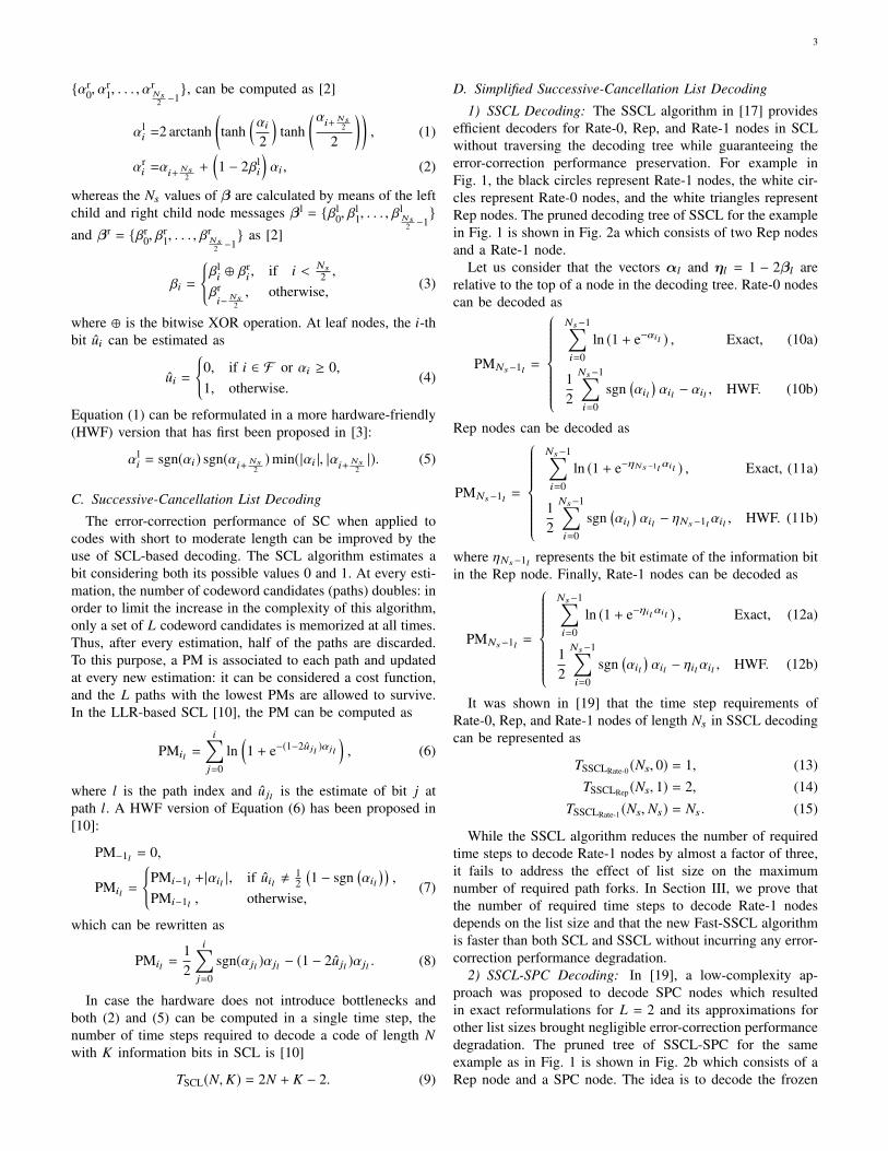
D. Simplified Successive-Cancellation List Decoding
1) SSCL Decoding: The SSCL algorithm in [17] providesefficient decoders for Rate-0, Rep, and Rate-1 nodes in SCLwithout traversing the decoding tree while guaranteeing theerror-correction performance preservation. For example inFig. 1, the black circles represent Rate-1 nodes, the white cir-cles represent Rate-0 nodes, and the white triangles representRep nodes. The pruned decoding tree of SSCL for the examplein Fig. 1 is shown in Fig. 2a which consists of two Rep nodesand a Rate-1 node.
Let us consider that the vectors αl and ηl = 1 − 2βl arerelative to the top of a node in the decoding tree. Rate-0 nodescan be decoded as
PMNs−1l =
Ns−1∑i=0
ln (1 + e−αil ) , Exact, (10a)
12
Ns−1∑i=0
sgn(αil
)αil − αil , HWF. (10b)
Rep nodes can be decoded as
PMNs−1l =
Ns−1∑i=0
ln (1 + e−ηNs−1lαil ) , Exact, (11a)
12
Ns−1∑i=0
sgn(αil
)αil − ηNs−1lαil , HWF. (11b)
where ηNs−1l represents the bit estimate of the information bitin the Rep node. Finally, Rate-1 nodes can be decoded as
PMNs−1l =
Ns−1∑i=0
ln (1 + e−ηilαil ) , Exact, (12a)
12
Ns−1∑i=0
sgn(αil
)αil − ηilαil , HWF. (12b)
It was shown in [19] that the time step requirements ofRate-0, Rep, and Rate-1 nodes of length Ns in SSCL decodingcan be represented as
TSSCLRate-0 (Ns, 0) = 1, (13)TSSCLRep (Ns, 1) = 2, (14)
TSSCLRate-1 (Ns, Ns) = Ns . (15)
While the SSCL algorithm reduces the number of requiredtime steps to decode Rate-1 nodes by almost a factor of three,it fails to address the effect of list size on the maximumnumber of required path forks. In Section III, we prove thatthe number of required time steps to decode Rate-1 nodesdepends on the list size and that the new Fast-SSCL algorithmis faster than both SCL and SSCL without incurring any error-correction performance degradation.
2) SSCL-SPC Decoding: In [19], a low-complexity ap-proach was proposed to decode SPC nodes which resultedin exact reformulations for L = 2 and its approximations forother list sizes brought negligible error-correction performancedegradation. The pruned tree of SSCL-SPC for the sameexample as in Fig. 1 is shown in Fig. 2b which consists of aRep node and a SPC node. The idea is to decode the frozen

4
RepRep Rate-1
(a) SSCL
Rep SPC
(b) SSCL-SPC
Fig. 2: (a) SSCL, and (b) SSCL-SPC decoding tree for P(8, 4)and {u0, u1, u2, u4} ∈ F .
bit in SPC nodes in the first step of the decoding process. Inorder to do that, the PM calculations in the HWF formulationwere carried out by only finding the LLR value of the leastreliable bit and using the LLR values at the top of the polarcode tree in the SCL decoding algorithm for the rest of thebits.
The least reliable bit in an SPC node of length Ns is foundas
imin = arg min0≤i<Ns
(|αi |), (16)
and the parity of it is derived as
γ =
Ns−1⊕i=0
(12(1 − sgn (αi))
). (17)
To satisfy the even-parity constraint, γ is found for each pathbased on (17). The PMs are then initialized as
PM0 =
{PM−1 +|αimin |, if γ = 1,PM−1 , otherwise.
(18)
In this way, the least reliable bit which corresponds to theeven-parity constraint is decoded first. For bits other than theleast reliable bit, the PM is updated as
PMi =
{PMi−1 +|αi | + (1 − 2γ)|αimin |, if ηi , sgn (αi) ,PMi−1 , otherwise.
(19)Finally, when all the bits are estimated, the least reliable bitis set to preserve the even-parity constraint as
βimin =
Ns−1⊕i=0
i,imin
βi . (20)
In [19], the time step requirements of SPC nodes of lengthNs in SSCL-SPC decoding was shown to be
TSSCL-SPCSPC (Ns, Ns − 1) = Ns + 1, (21)
which consists of one time step for (18), Ns −1 time steps for(19), and one time step for (20).
The SSCL-SPC algorithm reduces the number of requiredtime steps to decode SPC nodes by almost a factor of three,but as in the case of Rate-1 nodes, it fails to address the effectof list size on the maximum number of required path forks. InSection III, we prove that the number of required time steps todecode SPC nodes depends on the list size and that the newFast-SSCL-SPC algorithm is faster than SSCL-SPC withoutincurring any error-correction performance degradation.
III. FAST-SSCL DECODING
In this section, we propose a fast decoding approach forRate-1 nodes and use it to develop Fast-SSCL. We furtherpropose a fast decoding approach for SPC nodes in SSCL-SPCand use it to develop Fast-SSCL-SPC. To this end, we providethe exact number of path forks in Rate-1 and SPC nodesto guarantee error-correction performance preservation. Anypath splitting after that number is redundant and any pathsplitting less than that number cannot guarantee the error-correction performance preservation. We further show that inpractical applications, this number can be reduced with almostno error-correction performance loss. We use this phenomenonto optimize Fast-SSCL and Fast-SSCL-SPC for speed.
A. Guaranteed Error-Correction Performance Preservation
The fast Rate-1 and SPC decoders can be summarized bythe following theorems.
Theorem 1. In SSCL decoding with list size L, the numberof path splitting in a Rate-1 node of length Ns required to getthe exact same results as the conventional SSCL decoder is
min (L − 1, Ns) . (22)
The proposed technique results in TFast-SSCLRate-1 (Ns, Ns) =min (L − 1, Ns) which improves the required number of timesteps to decode Rate-1 nodes when L−1 < Ns . Every bit afterthe L−1-th can be obtained through hard decision on the LLRas
βil =
{0, if αil ≥ 0,1, otherwise,
(23)
without the need for path splitting. On the other hand, in casemin (L − 1, Ns) = Ns , all bits of the node need to be estimatedand the decoding automatically reverts to the process describedin [17]. The proof of the theorem is nevertheless valid for bothL − 1 < Ns and L − 1 ≥ Ns and is provided in [1].
The proposed theorem remains valid also for the HWFformulation that can be written as
PMil =
{PMi−1l +|αil |, if ηil , sgn
(αil
),
PMi−1l , otherwise.(24)
The proof of the theorem in the HWF formulation case is alsopresented in [1].
The result of Theorem 1 provides an exact number of pathforks in Rate-1 nodes for each list size in SCL decoding inorder to guarantee error-correction performance preservation.The Rate-1 node decoder of [15] empirically states thattwo path forks are required to preserve the error-correctionperformance. The following remarks are the direct results ofTheorem 1.
Remark 1. The Rate-1 node decoder of [15] for L = 2 isredundant.
Theorem 1 states that for a Rate-1 node of length Ns whenL = 2, the number of path splitting is min(L − 1, Ns) = 1.Therefore, there is no need to split the path after the leastreliable bit is estimated. [15] for L = 2 is thus redundant.

5
3 4 510−8
10−6
10−4
10−2
100
Eb/N0 [dB]
FER
3 4 510−9
10−7
10−5
10−3
10−1
Eb/N0 [dB]
BE
R
[17] [15]
Fig. 3: FER and BER performance comparison of SSCL [17]and the empirical method of [15] for P(1024, 860) when L =128. The CRC length is 32.
Remark 2. The Rate-1 node decoder of [15] falls short inpreserving the error-correction performance for higher ratesand larger list sizes.
For codes of higher rates, the number of Rate-1 nodes oflarger length increases [19]. Therefore, when the list size isalso large, min(L−1, Ns) � 2. The gap between the empiricalmethod of [15] and the result of Theorem 1 can introducesignificant error-correction performance loss. Fig. 3 providesthe frame error rate (FER) and bit error rate (BER) of decodinga P(1024, 860) code with SSCL of [17] and the empiricalmethod of [15] when the list size is 128. It can be seen thatthe error-correction performance loss reaches 0.25dB at FERof 10−5. In Section III-B, we show that the number of pathforks can be tuned for each list size to find a good trade-off between the error-correction performance and the speed ofdecoding.
Theorem 2. In SSCL-SPC decoding with list size L, thenumber of path forks in a SPC node of length Ns requiredto get the exact same results as the conventional SSCL-SPCdecoder is
min (L, Ns) . (25)
Following the time step calculation of SSCL-SPC, the proposed technique in Theorem 2 results inTFast-SSCL-SPCSPC (Ns, Ns − 1) = min (L, Ns) + 1 which improvesthe required number of time steps to decode SPC nodes whenL < Ns . Every bit after the L-th can be obtained through harddecision on the LLR as in (23) without the need for pathsplitting. In case min (L, Ns) = Ns , the paths need to be splitfor all bits of the node and the decoding automatically revertsto the process described in [19]. The proof of the theorem isnevertheless valid for both L < Ns and L ≥ Ns . We defer theproof to Appendix A.
The effectiveness of hard decision decoding after themin(L−1, Ns)-th bit in Rate-1 nodes and the min(L, Ns)-th bitin SPC nodes is due to the fact that the bits with high absolute
LLR values are more reliable and less likely to incur pathsplitting. However, whether path splitting must occur or notdepends on the list size L. The proposed Rate-1 node decoderis used in Fast-SSCL and Fast-SSCL-SPC algorithms and theproposed SPC node decoder is used in Fast-SSCL-SPC, whilethe decoders for Rate-0 and Rep nodes remain similar to thoseused in SSCL [17] such that
TFast-SSCLRate-0 (Ns, 0) = TFast-SSCL-SPCRate-0 (Ns, 0) = 1, (26)TFast-SSCLRep (Ns, 1) = TFast-SSCL-SPCRep (Ns, 1) = 2. (27)
It should be noted that the number of path forks is directlyrelated to the number of time steps required in the decodingprocess [10]. Therefore, when L < Ns , the time step require-ment of SPC nodes based on Theorem 2 is two time stepsmore than the time step requirement of Rate-1 nodes as inTheorem 1. However, if SPC nodes are not taken into accountas in Fast-SSCL decoding, the polar code tree needs to betraversed to find Rep nodes and Rate-1 nodes as shown inFig. 2a. For a SPC node of length Ns , this will result inadditional time step requirements as
TFast-SSCLSPC (Ns, Ns − 1) =2 log2 Ns − 2 + TFast-SSCLRep (2, 1)
+
log2 Ns−1∑i=1
TFast-SSCLRate-1 (2i, 2i).
For example, for a SPC node of length 64, Fast-SSCL withL = 4 results in TFast-SSCLSPC (64, 63) = 26, while Fast-SSCL-SPC with L = 4 results in TFast-SSCL-SPCSPC (64, 63) = 5. Table Isummarizes the number of time steps required to decode eachnode with different decoding algorithms.
In practical polar codes, there are many instances whereL − 1 < Ns for Rate-1 nodes and using the Fast-SSCLalgorithm can significantly reduce the number of requireddecoding time steps with respect to SSCL. Similarly, there aremany instances where L < Ns for SPC nodes and using theFast-SSCL-SPC algorithm can significantly reduce the numberof required decoding time steps with respect to SSCL-SPC.Fig. 4 shows the savings in time step requirements of a polarcode with three different rates. It should be noted that as therate increases, the number of Rate-1 and SPC nodes increases.This consequently results in more savings by going from SSCL(SSCL-SPC) to Fast-SSCL (Fast-SSCL-SPC).
B. Speed Optimization
The analysis in Section III-A provides exact reformulationsof SSCL and SSCL-SPC decoders without introducing anyerror-correction performance loss. However, in practical polarcodes, there are fewer required path forks for Fast-SSCLand Fast-SSCL-SPC in order to match the error-correctionperformance of SSCL and SSCL-SPC, respectively.
Without loss of generality, let us consider L − 1 < Ns forRate-1 nodes and L < Ns for SPC nodes such that Fast-SSCL and Fast-SSCL-SPC result in higher decoding speedsthan SSCL and SSCL-SPC, respectively. Let us now considerSRate-1 be the number of path forks in a Rate-1 node oflength Ns , and SSPC be the number of path forks in a SPCnode of length Ns where SRate-1 ≤ L − 1 and SSPC ≤ L. It

6
TABLE I: Time-Step Requirements of Decoding Different Nodes of Length Ns with List Size L.
Algorithm Rate-0 Rep Rate-1 SPC
SCL 2Ns − 2 2Ns − 1 3Ns − 2 3Ns − 3SSCL 1 2 Ns Ns + 2 log2 Ns − 2SSCL-SPC 1 2 Ns Ns + 1Fast-SSCL 1 2 min(L − 1, Ns ) 2 log2 Ns +
∑log2 Ns−1i=1 min(L − 1, Ns
2i )Fast-SSCL-SPC 1 2 min(L − 1, Ns ) min(L, Ns ) + 1
SSCL SSCL-SPC Fast-SSCL Fast-SSCL-SPC
21 22 23 24 25 26 27 28 290
200
400
600
800
1000
1200
L
Tim
est
eps
(a) P(1024, 256)
21 22 23 24 25 26 27 28 290
200
400
600
800
1000
1200
L
Tim
est
eps
(b) P(1024, 512)
21 22 23 24 25 26 27 28 290
200
400
600
800
1000
1200
L
Tim
est
eps
(c) P(1024, 768)
Fig. 4: Time-step requirements of SSCL, SSCL-SPC, Fast-SSCL, and Fast-SSCL-SPC decoding of (a) P(1024, 256), (b)P(1024, 512), and (c) P(1024, 768).
should be noted that SRate-1 = L − 1 and SSPC = L resultin optimal number of path forks as presented in Theorem 1and Theorem 2, respectively. The smaller the values of SRate-1and SSPC, the faster the decoders of Fast-SSCL and Fast-SSCL-SPC. Similar to (22) and (25), the new number ofrequired path forks for Rate-1 and SPC nodes can be statedas min(SRate-1, Ns) and min(SSPC, Ns), respectively.
The definition of the parameters SRate-1 and SSPC provides atrade-off between error-correction performance and speed ofFast-SSCL and Fast-SSCL-SPC. Let us consider CRC-aidedFast-SSCL decoding of P(1024, 512) with CRC length 16.Fig. 5 shows that for L = 2, choosing SRate-1 = 0 resultsin significant FER and BER error-correction performancedegradation. Therefore, when L = 2, the optimal value ofSRate-1 = 1 is used for Fast-SSCL. The optimal value of SRate-1for L = 4 is 3. However, as shown in Fig. 6, SRate-1 = 1results in almost the same FER and BER performance as theoptimal value of SRate-1 = 3. For L = 8, the selection ofSRate-1 = 1 results in ∼0.1 dB of error-correction performancedegradation at FER = 10−5 as shown in Fig. 7. However,selecting SRate-1 = 2 removes the error-correction performancegap to the optimal value of SRate-1 = 7. In the case of CRC-aided Fast-SSCL-SPC decoding of P(1024, 512) with 16 bitsof CRC, selecting SRate-1 = 1 and SSPC = 3 for L = 4 resultsin almost the same FER and BER performance as the optimal
values of SRate-1 = 3 and SSPC = 4 as shown in Fig. 8. Asillustrated in Fig. 9 for L = 8, the selection of SRate-1 = 2 andSSPC = 4 provides similar FER and BER performance as theoptimal values of SRate-1 = 7 and SSPC = 8.
IV. DECODER ARCHITECTURE
To evaluate the impact of the proposed techniques on apractical case, a SCL-based polar code decoder architectureimplementing Fast-SSCL and Fast-SSCL-SPC has been de-signed. Its basic structure is inspired to the decoders presentedin [9], [19], and it is portrayed in Fig. 10. The decoding flowfollows the one portrayed in Section II-C for a list size L. Thismeans that the majority of the datapath and of the memoryare replicated L times, and work concurrently on differentcandidate codewords and the associated LLR values.
Starting from the tree root, the tree is descended by re-cursively computing (5) and (2) on left and right branchesrespectively at each tree stage s, with a left-first rule. Thecomputations are performed by L sets of P processing ele-ments (PEs), where each set can be considered a standaloneSC decoder, and P is a power of 2. In case 2s > 2P, (5) and (2)require 2s/(2P) time steps to be completed, while otherwiseneeding a single time step. The updated LLR values are storedin dedicated memories.

7
1 2 310−4
10−3
10−2
10−1
100
Eb/N0 [dB]
FER
1 2 310−5
10−4
10−3
10−2
10−1
Eb/N0 [dB]
BE
R
SRate-1 = 0 SRate-1 = 1
Fig. 5: FER and BER performance comparison of Fast-SSCLdecoding of P(1024, 512) for L = 2 and different values ofSRate-1. The CRC length is 16.
1 2 3
10−5
10−4
10−3
10−2
10−1
100
Eb/N0 [dB]
FER
1 2 3
10−6
10−5
10−4
10−3
10−2
10−1
Eb/N0 [dB]
BE
R
SRate-1 = 0 SRate-1 = 1 SRate-1 = 3
Fig. 6: FER and BER performance comparison of Fast-SSCLdecoding of P(1024, 512) for L = 4 and different values ofSRate-1. The CRC length is 16.
The internal structure of PEs is shown in Fig. 11. EachPE receives as input two LLR values, outputting one. Thecomputations for both (5) and (2) are performed concurrently,and the output is selected according to is , that represents thes-th bit of the index i, where 0 ≤ i < N . The index i isrepresented with smax = log2 N bits, and identifies the nextleaf node to be estimated, and can be composed by observingthe path from the root node to the leaf node. From stage smaxdown to 0, for every left branch we set the corresponding bitof i to 0, and to 1 for every right branch.
When a leaf node is reached, the controller checks NodeSequence, identifying the leaf node as an information bit or afrozen bit. In case of a frozen bit, the paths are not split, andthe bit is estimated only as 0. All the L path memories areupdated with the same bit value, as are the LLR memories and
1 2 3
10−6
10−5
10−4
10−3
10−2
10−1
100
Eb/N0 [dB]
FER
1 2 310−7
10−6
10−5
10−4
10−3
10−2
10−1
Eb/N0 [dB]
BE
R
SRate-1 = 0 SRate-1 = 1SRate-1 = 2 SRate-1 = 7
Fig. 7: FER and BER performance comparison of Fast-SSCLdecoding of P(1024, 512) for L = 8 and different values ofSRate-1. The CRC length is 16.
1 2 310−5
10−4
10−3
10−2
10−1
100
Eb/N0 [dB]
FER
1 2 310−6
10−5
10−4
10−3
10−2
10−1
Eb/N0 [dB]
BE
R
SRate-1 = 1, SSPC = 2 SRate-1 = 1, SSPC = 3SRate-1 = 3, SSPC = 4
Fig. 8: FER and BER performance comparison of Fast-SSCL-SPC decoding of P(1024, 512) for L = 4 and different valuesof SRate-1 and SSPC. The CRC length is 16.
the β memories. On the other hand, in case of an informationbit, both 0 and 1 are considered. The paths are duplicatedand the PMs are calculated for the 2L candidates according to(8). They are subsequently filtered through the sorter module,designed for minimum latency. Every PM is compared to everyother in parallel: dedicated control logic uses the resultingsignals to return the values of the PMs of the surviving pathsand the newly estimated bits they are associated with. Thelatter are used to update the LLR memories, the β memoriesand the path memories, while also being sent to the CRCcalculation module to update the remainder.
All memories in the decoder are implemented as registers:this allows the LLR and β values to be read, updated by the

8
1 2 310−6
10−5
10−4
10−3
10−2
10−1
100
Eb/N0 [dB]
FER
1 2 310−7
10−6
10−5
10−4
10−3
10−2
10−1
Eb/N0 [dB]
BE
R
SRate-1 = 1, SSPC = 2 SRate-1 = 1, SSPC = 3SRate-1 = 1, SSPC = 4 SRate-1 = 2, SSPC = 2SRate-1 = 2, SSPC = 3 SRate-1 = 2, SSPC = 4SRate-1 = 7, SSPC = 8
Fig. 9: FER and BER performance comparison of Fast-SSCL-SPC decoding of P(1024, 512) for L = 8 and different valuesof SRate-1 and SSPC. The CRC length is 16.
PM Computationand Sorting
Controller CRC Unit
SC Decoders
· · ·...
PE
PE
...
PE
PE
1 · · · L
1...
P
Memories
Node Sequence
Channel LLRs
Fig. 10: Decoder architecture.
PEs, and written back in a single clock cycle. At the same time,the paths are either updated, or split and updated (dependingon the constituent code), and the new PMs computed. In thefollowing clock cycle, in case the paths were split, the PMsare sorted, paths are discarded and the CRC value updated.In case paths were not split, the PMs are not sorted, and theCRC update occurs in parallel with the following operation.
A. Memory Structure
The decoding flow described above relies on a number ofmemories that are shown in Fig. 12. The channel memorystores the N LLR values received from the channel at thebeginning of the decoding process. Each LLR value is quan-tized with QLLR bits, and represented with sign and magnitude.The high and low stage memories store the intermediate α
αli
αri
is
αi
αi+ Ns2
αouti
Fig. 11: PE architecture.
HighStage
Memory
...
LQLLR × P
N/P−
2 LowStage
Memory
...
LQLLR
2P−
2 ChannelMemory
QLLR
N
LLR Memories
PathMemory
...
L1
Nβ
Memory...
L1
N−
1
PMMemory
...
LQPM
1
Fig. 12: Memory architecture.
computed in (5) and (2). The high stage memory is usedto store LLR values related to stages with nodes of sizegreater than P. The number of PEs determines the numberof concurrent (5) or (2) that can be performed: for a nodein stage s, where 2s > 2P, a total of 2s/(2P) time stepsare needed to descend to the lower tree level. The depth ofthe high stage memory is thus
∑smax−1j=log2 P+1 2j/P = N/P − 2,
while its width is QLLR × P. On the other hand, the low stagememory stores the LLR values for stages where 2s ≤ 2P: thewidth of this memory is QLLR, while its depth is defined as∑log2 P−1
j=0 P/2j = 2P − 2. Both high and low stage memorywords are reused by nodes belonging to the same stage s,since once a subtree has been completely decoded, its LLRvalues are not needed anymore. While high and low stagememories are different for each path, the channel LLR valuesare shared among the L datapaths. Table II summarizes thememory read and write accesses for the aforementioned LLRmemories. When 2s = 2P, 2P LLR values are read from thehigh stage memory, and the P resulting LLR values are writtenin the low stage memory. The channel memory is read at smaxonly.
Each of the L candidate codewords is stored in one of theN-bit path memories, updated after every bit estimation. The βmemories hold the β values for each stage from 0 to smax − 1,for a total of N − 1 bits each. Each time a bit is estimated,all the β values it contributes to are concurrently updated.When the decoding of the left half of the SC decoding tree has

9
TABLE II: LLR Memory Access.
Stage READ WRITE
s = smax Channel High Stagelog2 P + 1 < s < smax High Stage High Stage
s = log2 P + 1 High Stage Low Stages < log2 P + 1 Low Stage Low Stage
TABLE III: Node Sequence Input Information for SSCL andSSCL-SPC.
Node Type Node Stage Node Size Frozen
RATE0 s 2s 1RATE1 s 2s 0REP1 s 2s − 1 1REP2 s 1 0DESCEND Next Node Next Node Next NodeLEAF 0 1 0/1
SPC1 s 1 1SPC2 s 2s − 1 0SPC3 s 2s 0
been completed, the β memories are reused for the right half.Finally, the PM memories store the L PM values computed in(8).
B. Special Nodes
The decoding flow and memory structure described beforeimplement the standard SCL decoding algorithm. The SSCL,SSCL-SPC and the proposed Fast-SSCL and Fast-SSCL-SPCalgorithms demand modifications in the datapath to accommo-date the simplified computations for Rate-0, Rate-1, Rep andSPC nodes.
As with standard SCL, the pattern of frozen and informationbits is known a priori given a polar code structure, the samecan be said for special nodes. In the modified architecture,the Node Sequence input in the controller (see Fig. 10) is notlimited to the frozen/information bit pattern, but it includesthe type of encountered nodes, their size and the tree stage inwhich they are encountered. Table III summarizes the contentof Node Sequence depending on the type of node for SSCLand SSCL-SPC, while in case of Fast-SSCL and Fast-SSCL-SPC Node Sequence is detailed in Table IV. The node stageallows the decoder to stop the tree exploration at the right level,and the node type identifies the operations to be performed.Each of the four node types is represented with one or moredecoding phases, each of which involves a certain number ofcodeword bits, identified by the node size parameter. Finally,the frozen bit parameter identifies a bit or set of bits as frozenor not. To limit the decoder complexity, the maximum nodestage for special nodes is limited to s = log2 P, thus themaximum node size is P. If the code structure identifies specialnodes with node size larger than P, they are considered ascomposed by a set of P-size special nodes.
• Rate-0 nodes are identified in the Node Sequence with asingle decoding phase. No path splitting occurs, and all
TABLE IV: Node Sequence Input Information for Fast-SSCLand Fast-SSCL-SPC.
Node Type Node Stage Node Size Frozen
RATE0 s 2s 1RATE1-1 s min(SRate-1, 2s ) 0RATE1-2 s 2s −min(SRate-1, 2s ) 0REP1 s 2s − 1 1REP2 s 1 0DESCEND Next Node Next Node Next NodeLEAF 0 1 0/1
SPC1 s 1 1SPC2-1 s min(SSPC, 2s ) 0SPC2-2 s 2s −min(SSPC, 2s ) − 1 0SPC3 s 2s 0
the 2s node bits are set to 0. The PM update requires asingle time step, as discussed in [19].
• Rate-1 nodes are composed of a single phase in bothSSCL and SSCL-SPC, in which paths are split 2s times.In case of Fast-SSCL and Fast-SSCL-SPC, each Rate-1is divided into two phases. The first takes care of themin(SRate-1, 2s) path forks, requiring as many time steps,while the second sets the remaining 2s − min(SRate-1, 2s)bits according to (23) and updates the PM according to(24). This second phase takes a single time step.
• Rep nodes are identified by two phases in the NodeSequence, the first of which takes care of the 2s − 1frozen bits similarly as Rate-0 nodes do, and the secondestimates the single information bit. Each of these twophases lasts a single time step.
• SPC nodes are split in three phases in the original SSCL-SPC formulation. The first phase takes care of the frozenbit, and computes both (16) and (17), initializing the PMas (18) in a time step. The extraction of the least reliablebit in (16) is performed through a comparison tree thatcarries over both the index and the value of the LLR.The second phase estimates the 2s − 1 information bits,splitting the path as many times in as many time steps.During this phase, each time a bit is estimated, it isXORed with the previous β values: this operation isuseful to compute (20). The update of βimin is finallyperformed in the third phase, that takes a single time step.Moving to Fast-SSCL-SPC, the second SPC phase is splitin two, similarly to what happens to the Rate-1 node.
• Descend is a non-existing node type that is inserted forone clock cycle in Node Sequence for control purposesafter every special node. The node size and stage associ-ated with this label are those of the following node. TheDescend node type is used by the controller module.
• Leaf nodes identify all nodes that can be found at s = 0,for which the standard SCL algorithm applies.
The decoding of special nodes requires a few major changesin the decoder architecture.
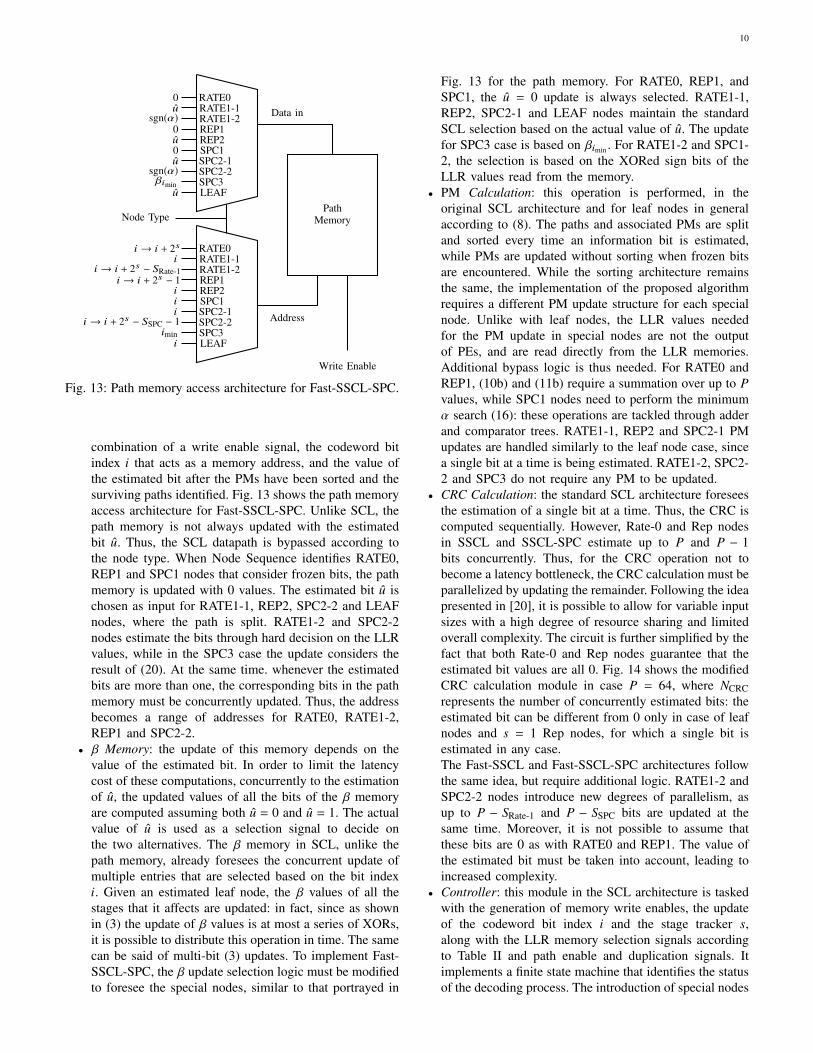
• Path Memory: each path memory is an array of Nregisters, granting concurrent access to all bits with a 1-bit granularity. In SCL, the path update is based on the
10
PathMemory
Address
Data in
Write Enable
Node Type
RATE0RATE1-1RATE1-2REP1REP2SPC1SPC2-1SPC2-2SPC3LEAF
0u
sgn(α)0u0u
sgn(α)βimin
u
RATE0RATE1-1RATE1-2REP1REP2SPC1SPC2-1SPC2-2SPC3LEAF
i → i + 2si
i → i + 2s − SRate-1i → i + 2s − 1
iii
i → i + 2s − SSPC − 1imin
i
Fig. 13: Path memory access architecture for Fast-SSCL-SPC.
combination of a write enable signal, the codeword bitindex i that acts as a memory address, and the value ofthe estimated bit after the PMs have been sorted and thesurviving paths identified. Fig. 13 shows the path memoryaccess architecture for Fast-SSCL-SPC. Unlike SCL, thepath memory is not always updated with the estimatedbit u. Thus, the SCL datapath is bypassed according tothe node type. When Node Sequence identifies RATE0,REP1 and SPC1 nodes that consider frozen bits, the pathmemory is updated with 0 values. The estimated bit u ischosen as input for RATE1-1, REP2, SPC2-2 and LEAFnodes, where the path is split. RATE1-2 and SPC2-2nodes estimate the bits through hard decision on the LLRvalues, while in the SPC3 case the update considers theresult of (20). At the same time. whenever the estimatedbits are more than one, the corresponding bits in the pathmemory must be concurrently updated. Thus, the addressbecomes a range of addresses for RATE0, RATE1-2,REP1 and SPC2-2.
• β Memory: the update of this memory depends on thevalue of the estimated bit. In order to limit the latencycost of these computations, concurrently to the estimationof u, the updated values of all the bits of the β memoryare computed assuming both u = 0 and u = 1. The actualvalue of u is used as a selection signal to decide onthe two alternatives. The β memory in SCL, unlike thepath memory, already foresees the concurrent update ofmultiple entries that are selected based on the bit indexi. Given an estimated leaf node, the β values of all thestages that it affects are updated: in fact, since as shownin (3) the update of β values is at most a series of XORs,it is possible to distribute this operation in time. The samecan be said of multi-bit (3) updates. To implement Fast-SSCL-SPC, the β update selection logic must be modifiedto foresee the special nodes, similar to that portrayed in
Fig. 13 for the path memory. For RATE0, REP1, andSPC1, the u = 0 update is always selected. RATE1-1,REP2, SPC2-1 and LEAF nodes maintain the standardSCL selection based on the actual value of u. The updatefor SPC3 case is based on βimin . For RATE1-2 and SPC1-2, the selection is based on the XORed sign bits of theLLR values read from the memory.
• PM Calculation: this operation is performed, in theoriginal SCL architecture and for leaf nodes in generalaccording to (8). The paths and associated PMs are splitand sorted every time an information bit is estimated,while PMs are updated without sorting when frozen bitsare encountered. While the sorting architecture remainsthe same, the implementation of the proposed algorithmrequires a different PM update structure for each specialnode. Unlike with leaf nodes, the LLR values neededfor the PM update in special nodes are not the outputof PEs, and are read directly from the LLR memories.Additional bypass logic is thus needed. For RATE0 andREP1, (10b) and (11b) require a summation over up to Pvalues, while SPC1 nodes need to perform the minimumα search (16): these operations are tackled through adderand comparator trees. RATE1-1, REP2 and SPC2-1 PMupdates are handled similarly to the leaf node case, sincea single bit at a time is being estimated. RATE1-2, SPC2-2 and SPC3 do not require any PM to be updated.
• CRC Calculation: the standard SCL architecture foreseesthe estimation of a single bit at a time. Thus, the CRC iscomputed sequentially. However, Rate-0 and Rep nodesin SSCL and SSCL-SPC estimate up to P and P − 1bits concurrently. Thus, for the CRC operation not tobecome a latency bottleneck, the CRC calculation must beparallelized by updating the remainder. Following the ideapresented in [20], it is possible to allow for variable inputsizes with a high degree of resource sharing and limitedoverall complexity. The circuit is further simplified by thefact that both Rate-0 and Rep nodes guarantee that theestimated bit values are all 0. Fig. 14 shows the modifiedCRC calculation module in case P = 64, where NCRCrepresents the number of concurrently estimated bits: theestimated bit can be different from 0 only in case of leafnodes and s = 1 Rep nodes, for which a single bit isestimated in any case.The Fast-SSCL and Fast-SSCL-SPC architectures followthe same idea, but require additional logic. RATE1-2 andSPC2-2 nodes introduce new degrees of parallelism, asup to P − SRate-1 and P − SSPC bits are updated at thesame time. Moreover, it is not possible to assume thatthese bits are 0 as with RATE0 and REP1. The value ofthe estimated bit must be taken into account, leading toincreased complexity.
• Controller: this module in the SCL architecture is taskedwith the generation of memory write enables, the updateof the codeword bit index i and the stage tracker s,along with the LLR memory selection signals accordingto Table II and path enable and duplication signals. Itimplements a finite state machine that identifies the statusof the decoding process. The introduction of special nodes

11
NCRC = 64
NCRC = 63
NCRC = 32
NCRC = 31
NCRC = 16
NCRC = 15
NCRC = 8
NCRC = 7
NCRC = 4
NCRC = 3
NCRC = 2
NCRC = 1Estimated
bit
Remainder
Node Type
Node Size
Fig. 14: CRC architecture for SSCL and SSCL-SPC.
demands that most of the control signal generation logicis modified. Of particular importance is the fact that, inthe SCL architecture, the update of i is bound to havingreached a leaf node, i.e. s = 0. In Fast-SSCL-SPC, it isinstead linked to s being equal to the special node stage.The index i is moreover incremented of the amount ofbits estimated in a single time step, depending on thetype of node. Memory write enables are also bound tohaving reached the special node stage, and not only tos = 0.
V. RESULTS
A. Hardware Implementation
The architecture designed in Section IV has been describedin the VHDL language and synthesized in TSMC 65 nmCMOS technology. Implementation results are provided inTable V for different decoders: along with the Fast-SSCL andFast-SSCL-SPC described in this work, the SCL, SSCL andSSCL-SPC decoders proposed in [19] are presented as well.Each decoder has been synthesized with three list sizes (L =2, 4, 8), while the Fast-SSCL and Fast-SSCL-SPC architectureshave been synthesized for considering different combinationsof SRate-1 and SSPC, as portrayed in Section III-B. Quantizationvalues are the same used in [19], i.e. 6 bits for LLR valuesand 8 bits for PMs, with two fractional bits each. All memoryelements have been implemented through registers and thearea results include both net area and cell area. The reportedthroughput is coded.
All Fast-SSCL and Fast-SSCL-SPC, regardless of the valueof SRate-1 and SSPC, show a substantial increase in area oc-
cupation with respect to SSCL and SSCL-SPC. The maincontributing factors to the additional area overhead are three:• In SSCL and SSCL-SPC, the CRC computation needs to
be parallelized, since in Rep and Rate-0 nodes multiplebits are updated at the same time. However, the bitvalue is known at design time, since they are frozenbits. This, along with the fact that 0 is neutral in theXOR operations required by CRC calculation, limits therequired additional area overhead. On the contrary, inFast-SSCL and Fast-SSCL-SPC, Rate-1 and SPC nodesupdate multiple bits within the same time step (SPC2-2and RATE1-2 stages). In these cases, however, they areinformation bits, whose values cannot be known at designtime: the resulting parallel CRC tree is substantially widerand deeper than the ones for Rate-0 and Rep nodes.Moreover, with increasing number of CRC trees, theselection logic becomes more cumbersome.
• A similar situation is encountered for the β memoryupdate signal. As described in the previous section, theβ memory update values are computed assuming bothestimated values, and the actual value of u is used as aselection signal. In SSCL and SSCL-SPC the multiple-bit update does not constitute a problem since all theestimated bits are 0 and the β memory content does notneed to be changed. On the contrary, in Fast-SSCL andFast-SSCL-SPC, the value of the estimated informationbits might change the content of the β memory. Moreover,since β is computed as (3), the update of β bits dependson previous bits as well as the newly estimated ones.Thus, an XOR tree is necessary to compute the rightselection signal for every information bit estimated inSPC2-2 and RATE1-2 stages.
• The aforementioned modifications considerably lengthenthe system critical path. In case of large code length, smalllist size, or large P, the critical path starts in the controllermodule, in particular in the high stage memory addressinglogic, goes through the multiplexing structure that routesLLR values to the PEs, and ends after the PM update. Incase of large list sizes or short code length, the criticalpath passes through the PM sorting and path selectionlogic, and through the parallel CRC computation. Thus,pipeline registers have been inserted to lower the impactof critical path, at the cost of additional area occupation.
Fast-SSCL and Fast-SSCL-SPC implementations show con-sistent throughput improvements with respect to previouslyproposed architectures. The gain is lower than what is shownto be theoretically achievable in Fig. 4. This is due to theaforementioned pipeline stages, that increase the number ofsteps needed to complete the decoding of component codes.
B. Comparison with Previous Works
The Fast-SSCL-SPC hardware implementation presented inthis paper for P(1024, 512) and P = 64 is compared withthe state-of-the-art architectures in [11]–[14], [19] and theresults are provided in Table VI. The architectures presentedin [12]–[14] were synthesized based on 90 nm technology: fora fair comparison, their results have been converted to 65 nm

12
TABLE V: TSMC 65 nm Implementation Results for P(1024, 512) and P = 64.
Implementation L SRate-1 SSPCArea
[mm2]Frequency
[MHz]Throughput
[Mb/s]
SCL2 7 7 0.599 1031 3894 7 7 0.998 961 3638 7 7 2.686 722 272
SSCL2 7 7 0.643 1031 11084 7 7 1.192 961 10338 7 7 2.958 722 776
SSCL-SPC2 7 7 0.684 1031 12294 7 7 1.223 961 11468 7 7 3.110 722 861
Fast-SSCL
2 1 7 0.871 885 15794 1 7 1.536 840 14994 3 7 1.511 840 14468 2 7 3.622 722 10538 7 7 3.588 722 827
Fast-SSCL-SPC
2 1 2 1.048 885 18614 1 3 1.822 840 16084 3 4 1.797 840 13388 2 4 3.975 722 11988 7 8 3.902 722 959
technology using a factor of 90/65 for the frequency and afactor of (65/90)2 for the area. The synthesis results in [11]were carried out in 65 nm technology but reported in 90 nmtechnology. Therefore, a reverse conversion was applied toconvert the results back to 65 nm technology.
The architecture in this paper shows 72% higher throughputand 42% lower latency with respect to the multibit decisionSCL decoder architecture of [11] for L = 4. However, thearea occupation of [11] is smaller, leading to a higher areaefficiency than the design in this paper.
The symbol-decision SCL decoder architecture of [12]shows lower area occupation than the design in this paperfor L = 4 but it comes at the cost of lower throughput andhigher latency. Our decoder architecture achieves 192% higherthroughput and 66% lower latency than [12] which resulted in17% higher area efficiency.
The high throughput SCL decoder architecture of [13] forL = 2 requires lower area occupation than our design but itcomes at the expense of lower throughput and higher latency.Moreover, the design in [13] relies on parameters that needto be tuned for each code, and it is shown in [13] that achange of code can result in more than 0.2 dB error-correctionperformance loss. For L = 4, our decoder not only achieveshigher throughput and lower latency than [13], but also itoccupies a smaller area. This in turn yields a 12% increasein the area efficiency in comparison with [13].
The multimode SCL decoder in [14] relies on a highernumber of PEs than our design: nevertheless, it yields lowerthroughput and higher latency than the architecture proposedin this paper for L = 4. It should be noted that [14] is based onthe design presented in [13], whose code-specific parametersmay lead to substantial error-correction performance degrada-tion. On the contrary, the design in this paper is targeted for
speed and flexibility and can be used to decode any polar codeof any length.
Compared to our previous work [19], that has the samedegree of flexibility of the proposed design, this decoderachieves 51% higher throughput and 34% lower latency forL = 2, and 40% higher throughput and 28% lower latency forL = 4. However, the higher area occupation of the new designyields lower area efficiencies than [19] for L = {2, 4}. ForL = 8, the proposed design has 39% higher throughput and29% lower latency than [19], which results in 9% increase inarea efficiency. The reason is that for L = 8, the sorter is quitelarge and falls on the critical path. Consequently, the maximumachievable frequency for the proposed design is limited by thesorter and not by Rate-1 and SPC nodes as opposed to theL = {2, 4} case. This results in the same maximum achievablefrequency for both designs, hence, higher throughput and areaefficiency.
Fig. 15 plots the area occupation against the decodinglatency for all the decoders considered in Table VI. For eachvalue of L, the design proposed in this work have the shortestlatency, shown by their leftmost position on the graph.
VI. CONCLUSION
In this work, we have proven that the list size in polardecoders sets a limit to the useful number of path forks inRate-1 and SPC nodes. We thus propose Fast-SSCL and Fast-SSCL-SPC polar code decoding algorithms that, dependingon L and the number of performed path forks, can reducethe number of required time steps of more than 75% at noerror-correction performance cost. Hardware architectures forthe proposed algorithms have been described and implementedin CMOS 65 nm technology. They have a very high degreeof flexibility and can decode any polar code, regardless of its

13
TABLE VI: Comparison with State-of-the-Art Decoders.
This work [11] [12]† [13]† [14]† [19]
L 2 4 8 4 4 2 4 4 2 4 8P 64 64 64 64 64 64 64 256 64 64 64
Area [mm2] 1.048 1.822 3.975 0.62 0.73 1.03 2.00 0.99 0.68 1.22 3.11Frequency [MHz] 885 840 722 498 692 586 558 566 1031 961 722
Throughput [Mb/s] 1861 1608 1198 935 551 1844 1578 1515 1229 1146 861Latency [µs] 0.55 0.64 0.85 1.10 1.86 0.57 0.66 0.69 0.83 0.89 1.19
Area Efficiency [Mb/s/mm2] 1776 883 301 1508 755 1790 789 1530 1807 939 277
†The results are originally based on TSMC 90 nm technology and are scaled to TSMC 65 nm technology.
10−0.2 100 100.2
10−0.2
100
100.2
100.4
100.6
This work
[13]
[19]
This work
[11]
[12]
[13]
[14]
[19]
This work
[19]
Latency [µs]
Are
a[m
m2 ]
L = 2L = 4L = 8
Fig. 15: Comparison with state-of-the-art decoders.
rate. The proposed decoder is the fastest SCL-based decoderin literature: sized for N = 1024 and L = 2, it yields a 1.861Gb/s throughput with an area occupation of 1.048 mm2. Thesame design, sized for L = 4 and L = 8, leads to throughputsof 1.608 Gb/s and 1.198 Gb/s, and areas of 1.822 mm2 and3.975 mm2, respectively.
APPENDIX APROOF OF THEOREM 2
Proof. In order to prove Theorem 2, we note that the firststep is to initialize the PMs based on (18). Therefore, theleast reliable bit needs to be estimated first. For the bits otherthan the least reliable bit, the PMs are updated based on (19).However, the term (1 − 2γ)|αimin | is constant for all the bitestimations in the same path. Therefore, we can define a newset of Ns − 1 LLR values as
αim = αi + sgn(αi)(1 − 2γ)|αimin |, (28)
for i , imin and 0 ≤ im < Ns − 1, which results in
|αim | = |αi | + (1 − 2γ)|αimin |. (29)
The problem is now reduced to a Rate-1 node of length Ns −1 which, with the result of Theorem 1, can be decoded byconsidering only min(L − 1, Ns − 1) path splitting. Adding thebit estimation for imin, SPC nodes can be decoded by splitting
paths min(L, Ns) times while guaranteeing the same results asin SSCL-SPC. Theorem 2 is consequently proven. �
REFERENCES
[1] S. A. Hashemi, C. Condo, and W. J. Gross, “Fast simplified successive-cancellation list decoding of polar codes,” in IEEE Wireless Commun.and Netw. Conf., March 2017, pp. 1–6.
[2] E. Arıkan, “Channel polarization: A method for constructing capacity-achieving codes for symmetric binary-input memoryless channels,” IEEETrans. Inf. Theory, vol. 55, no. 7, pp. 3051–3073, July 2009.
[3] C. Leroux, A. Raymond, G. Sarkis, and W. Gross, “A semi-parallelsuccessive-cancellation decoder for polar codes,” IEEE Trans. SignalProcess., vol. 61, no. 2, pp. 289–299, January 2013.
[4] A. Alamdar-Yazdi and F. R. Kschischang, “A simplified successive-cancellation decoder for polar codes,” IEEE Commun. Lett., vol. 15,no. 12, pp. 1378–1380, December 2011.
[5] G. Sarkis, P. Giard, A. Vardy, C. Thibeault, and W. Gross, “Fast polardecoders: Algorithm and implementation,” IEEE J. Sel. Areas Commun.,vol. 32, no. 5, pp. 946–957, May 2014.
[6] I. Tal and A. Vardy, “List decoding of polar codes,” IEEE Trans. Inf.Theory, vol. 61, no. 5, pp. 2213–2226, May 2015.
[7] I. Dumer and K. Shabunov, “Near-optimum decoding for subcodes ofReed-Muller codes,” in IEEE Int. Symp. on Inform. Theory, 2001, p.329.
[8] “Final report of 3GPP TSG RAN WG1 #87 v1.0.0,”http://www.3gpp.org/ftp/tsg ran/WG1 RL1/TSGR1 87/Report/FinalMinutes report RAN1%2387 v100.zip, Reno, USA, November 2016.
[9] A. Balatsoukas-Stimming, A. J. Raymond, W. J. Gross, and A. Burg,“Hardware architecture for list successive cancellation decoding of polarcodes,” IEEE Trans. Circuits Syst. II, vol. 61, no. 8, pp. 609–613, August2014.
[10] A. Balatsoukas-Stimming, M. Bastani Parizi, and A. Burg, “LLR-basedsuccessive cancellation list decoding of polar codes,” IEEE Trans. SignalProcess., vol. 63, no. 19, pp. 5165–5179, October 2015.
[11] B. Yuan and K. K. Parhi, “LLR-based successive-cancellation listdecoder for polar codes with multibit decision,” IEEE Trans. CircuitsSyst. II, vol. 64, no. 1, pp. 21–25, January 2017.
[12] C. Xiong, J. Lin, and Z. Yan, “Symbol-decision successive cancellationlist decoder for polar codes,” IEEE Trans. Signal Process., vol. 64, no. 3,pp. 675–687, February 2016.
[13] J. Lin, C. Xiong, and Z. Yan, “A high throughput list decoder architecturefor polar codes,” IEEE Trans. VLSI Syst., vol. 24, no. 6, pp. 2378–2391,June 2016.
[14] C. Xiong, J. Lin, and Z. Yan, “A multimode area-efficient SCL polardecoder,” IEEE Trans. VLSI Syst., vol. 24, no. 12, pp. 3499–3512,December 2016.
[15] G. Sarkis, P. Giard, A. Vardy, C. Thibeault, and W. J. Gross, “Fast listdecoders for polar codes,” IEEE J. Sel. Areas Commun., vol. 34, no. 2,pp. 318–328, February 2016.
[16] S. A. Hashemi, C. Condo, and W. J. Gross, “List sphere decodingof polar codes,” in Asilomar Conf. on Signals, Syst. and Comput.,November 2015, pp. 1346–1350.
[17] S. A. Hashemi, C. Condo, and W. J. Gross, “Simplified successive-cancellation list decoding of polar codes,” in IEEE Int. Symp. on Inform.Theory, July 2016, pp. 815–819.
[18] S. A. Hashemi, C. Condo, and W. J. Gross, “Matrix reordering forefficient list sphere decoding of polar codes,” in IEEE Int. Symp. onCircuits and Syst., May 2016, pp. 1730–1733.

14
[19] S. A. Hashemi, C. Condo, and W. J. Gross, “A fast polar code listdecoder architecture based on sphere decoding,” IEEE Trans. CircuitsSyst. I, vol. 63, no. 12, pp. 2368–2380, December 2016.
[20] C. Condo, M. Martina, G. Piccinini, and G. Masera, “Variable paral-lelism cyclic redundancy check circuit for 3GPP-LTE/LTE-Advanced,”IEEE Signal Process. Lett., vol. 21, no. 11, pp. 1380–1384, November2014.
Seyyed Ali Hashemi was born in Qaemshahr, Iran.He received the B.Sc. degree in electrical engineer-ing from Sharif University of Technology, Tehran,Iran, in 2009 and the M.Sc. degree in electricaland computer engineering from the University ofAlberta, Edmonton, AB, Canada, in 2011. He iscurrently working toward the Ph.D. degree in electri-cal and computer engineering at McGill University,Montreal, QC, Canada. He was the recipient ofa Best Student Paper Award at the 2016 IEEEInternational Symposium on Circuits and Systems
(ISCAS 2016). His research interests include error-correcting codes, hard-ware architecture optimization, and VLSI implementation of digital signalprocessing systems.
Carlo Condo received the M.Sc. degree in elec-trical and computer engineering from Politecnicodi Torino, Italy, and the University of Illinois atChicago, IL, USA, in 2010. He received the Ph.D.degree in electronics and telecommunications en-gineering from Politecnico di Torino and TelecomBretagne, France, in 2014. Since 2015, he has beena postdoctoral fellow at the ISIP Laboratory, McGillUniversity. His Ph.D. thesis was awarded a mentionof merit as one of the five best of 2013/2014 bythe GE association, and he has been the recipient of
two conference best paper awards (SPACOMM 2013 and ISCAS 2016). Hisresearch is focused on channel coding, design and implementation of encoderand decoder architectures, and digital signal processing.
Warren J. Gross (SM’10) received the B.A.Sc.degree in electrical engineering from the Universityof Waterloo, Waterloo, ON, Canada, in 1996, andthe M.A.Sc. and Ph.D. degrees from the Universityof Toronto, Toronto, ON, Canada, in 1999 and 2003,respectively. Currently, he is Professor and AssociateChair (Academic Affairs) with the Department ofElectrical and Computer Engineering, McGill Uni-versity, Montreal, QC, Canada. His research interestsare in the design and implementation of signal pro-cessing systems and custom computer architectures.
Dr. Gross served as Chair of the IEEE Signal Processing Society TechnicalCommittee on Design and Implementation of Signal Processing Systems. Hehas served as General Co-Chair of IEEE GlobalSIP 2017 and IEEE SiPS2017, and as Technical Program Co-Chair of SiPS 2012. He has also servedas organizer for the Workshop on Polar Coding in Wireless Communicationsat WCNC 2017, the Symposium on Data Flow Algorithms and Architecturefor Signal Processing Systems (GlobalSIP 2014) and the IEEE ICC 2012Workshop on Emerging Data Storage Technologies. Dr. Gross served asAssociate Editor for the IEEE Transactions on Signal Processing and currentlyis a Senior Area Editor. Dr. Gross is a Senior Member of the IEEE and alicensed Professional Engineer in the Province of Ontario.