FARMER HCF 2019 ENG - reventongroup.eu · technical documentation air water heaters in epp casing...
18
Technical documentation AIR WATER HEATERS IN EPP CASING FARMER HCF SERIES MODELS: REVENTON GROUP FARMER HCF IP54-3S REVENTON GROUP FARMER HCF IP65
Transcript of FARMER HCF 2019 ENG - reventongroup.eu · technical documentation air water heaters in epp casing...
Technical documentationAIR WATER HEATERS IN EPP CASING FARMER HCF SERIES
MODELS:
REVENTON GROUP FARMER HCF IP54-3SREVENTON GROUP FARMER HCF IP65
Table of contents1.INTRODUCTION 1.1 PRECAUTIONS 1.2 TRANSPORT 1.3 PACKAGE CONTENT 1.4 USE 2. DEVICE CHARACTERISTICS 2.1. INTERNATIONAL PROTECTION DEGREE IP 2.2. CONSTRUCTION AND PRINCIPLE OF OPERATION 2.3. LCE COATING 2.4. DEVICE DIMENSIONS 2.5. DEVICE TECHNICAL DATA3. ASSEMBLY 3.1. GENERAL PRINCIPLES 3.2. ROTATING MOUNTING BRACKET4. INSTALLATION INSTRUCTIONS 4.1. CONNECTION OF THE DEVICE TO THE HYDAULIC SYSTEM 4.2. CONNECTION OF THE DEIVCE TO THE ELECTRICAL SYSTEM 5. PRECAUTIONS & WARNINGS6. CONTROLS 7. CONNECTION SCHEMES8. TERMS OF WARRANTY
1. INTRODUCTION
Thank you very much for purchasing Reventon Group device. We would like to congratulate you on excellent choice. Please read and keep this manual.
1.1 PRECAUTIONS
The buyer and the user of the air water heater Reventon Group brand should read carefully the following instructions and proceed to the content recommendations. Proceeding due to the following instruction guarantees the correct usage and safety. In case of any doubts please contact directly the producer Reventon Group sp. z o.o. The producer reserves the rights to make changes to the technical documentation without previous notice. Reventon Group sp. z o.o. is not responsible for the damages which occur due to improper installation, not keeping the device in repair or using the device out of line. The installation should be carried out by the professional installers, who possess the qualifications to install these types of devices. The installers are responsible for making the installation as instructed in the technical data. In case of unserviceable please plug out the device and contact with the authorized for repair person or the supplier. During the installation, use, service and periodical inspections all regulations and safety rules must be followed.
1.2 TRANSPORT
During the acceptance of goods, it is needed to check the device to exclude any damages. During the transport, it is needed to use the proper equipment, it is necessary to carry the device by two people. In case of any damages please fill in the damage report in presence of the supplier.
1.3 PACKAGE CONTENT
- heater- operation and maintenance manual and warranty card
1.4 USE
Reventon Group Farmer HCF heating devices are designed for heating or cooling surfaces in which aggressive conditions prevail, i.e. high content of acids, ammonia and high concentration of dust. However, heaters should not be used in highly corrosive environments for aluminum, copper and steel. The devices should also not be installed in rooms where they would be exposed to the high humidity or direct water action, exceeding the fan's resistance to water penetration (see IP protection degree).
2. DEVICE CHARACTERISTICS
2.1INTERNATIONAL PROTECTION DEGREE IP
Determines the tightness of the electrical device (fan motor), which is defied by two digits:
ź first characteristic digit - specifies protection of the device against access to dangerous parts as well as against penetration of solids
ź second characteristic digit – determines the resistance of the engine to the water ingress, its waterproofness
ENG TECHNICAL DOCUMENTATON Fan motors of the Farmer HCF series have following IP:
5 - protection against access to hazardous parts by wire with a diameter of 1 mm or more and against dust in quantities which might impair the proper functioning of the equipment;4 – protection against splashes of the water from any direction.
6- protection against access to hazardous parts by wire with a diameter of 1 mm or more and against dust (total dust tightness);5 – protection against stream of the water (12.5 l/min) from any direction
2.2 CONSTRUCTION AND PRINCIPLE OF OPERATION
Casing: made of expanded polypropylene (EPP). This material is characterized by low density (light weighted) and high chemical and physical resistance. It has an excellent sound and thermal insulation properties. Moreover, material is environmentally friendly and "green", i.e. 100% recyclable.
Air stators: made of polypropylene PP. It is possible to adjust manually the air stators to achieve the needed direction of the air flow. There are also versions with confusor (increased airflow range) or with diffuser 360° (better mixing of supplied and room air).
Heating coil: made of copper and aluminum. It is covered by LCE coating. Supplied by distribution medium (heating or cooling), which circulates through the coil and releases or extracts heat from the air. The coil has the following technical parameters: the maximum temperature of the heating factor is 120°C; maximum pressure 1,6 MPa; headers diameter ¾”. Farmer HCF series have a double row heat exchanger.
Axial blowing fan IP54 (Farmer HCF IP54-3S): made of galvanized steel. Fan has to ensure air flow through the exchanger. It has a single- and three phase motor with the following parameters: protection degree IP54, rate current 0,7-1,08 A (depending on the operating mode). Diameter of the fan is 450 mm.
Axial blowing fan IP65 (Farmer HCF IP65): protective grid made of galvanized steel, blades and casing made of plastic. Fan has to ensure air flow through the exchanger. It has a single-, three phase motor with the following parameters: protection degree IP65, rated current 2A. Diameter of the fan is 450 mm.
Rotating mounting bracket (optional equipment): enables the deviceto be installed in several configurations (depending on the requirements) and the unit to be rotated in a horizontal plane.
Farmer HCF IP54-3S
Farmer HCF IP65
2.3 LCE COATING
The coating technology is based on immersion of the exchanger in the liquid LCE, which allows ptotection of the whole surface of the exchanger. The LCE coating is waterproof and protects the heater exchanger from corrosion, mould and bacteria without compromising heat transfer efficiency. It is flexible enough not to be teared during thermal expansion of metal parts.
Periodic maintenance guarantees the resistance of the LCE coating to the following concentrations of chemical factors:
In addition the above LCE COATING demonstrates high resistance to fumes of the following: Lactic Acid, Oxalic Acid, Humic Acid, Saltwater and NOx.
Agent Concentration
Hydrochloric Acid 30%
Sulphuric Acid 30%
Phosphoric Acid 50%
Acetic Acid 10%
Sodium Hydroxide 10%
Ammonia in the air 30 ppm
Urea in the air 30 ppm
Trichloroethylene 30 ppm
Toluene 25 ppm
Methylated Spirits 30 ppm
Mineral Turps 30 ppm
MEK 25 ppm
Acetone 25 ppm
Hydrogen Sulphide 30 ppm
13 12 10 9 8 17 15 12 11 9 13 11 9 7 6
9 8 6 5 4 13 9 6 4 24 3 2 1 1
TECHNOLOGY HAS THE FOLLOWING CERTIFICATES:
ASTM B1 17 salt spray test 1 0000 hours in heating/cooling cycles changingtemperatures between 60 °C and 5°C.ASTM G 85 A1 Acetic Acid-Salt spray test to prove positive impact on coils used in food industry.ASTM G87 Same as G85 utilizing acidic SO2 electrolyte.ASTM D552 Flexibility test, which investigates flexibility of coating to bond to the substrate surface of coil.ASTM G 85 A5 Indirect spraying of dilute salt and ammonium sulphate at 23°C and followed by 1 hour exposure of dry air at 35°C. Test proving resistance in saltcontaining environment and industrial applications.ASTM G 21 that examines resistance to fungi. Important aspect for evaporators.
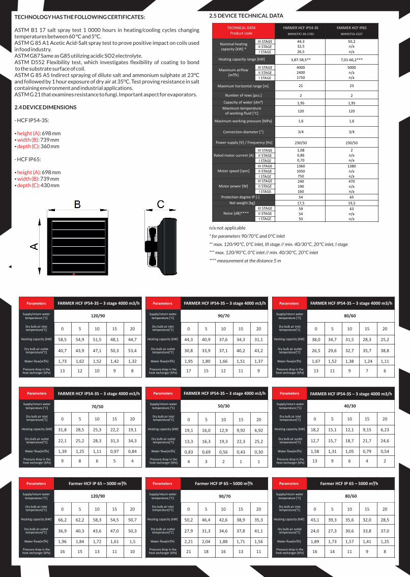
2.4 DEVICE DIMENSIONS
- HCF IP54-3S:
ź : 698 mmź : 739 mmź : 360 mm
- HCF IP65:
ź : 698 mmź : 739 mmź : 430 mm
height (A)width (B)depth (C)
height (A)width (B)depth (C)
TECHNICAL DATA
Product code
FARMER HCF IP54-3S
WHHCF47-3S-1765
III STAGE
II STAGE
I STAGE
III STAGE
II STAGE
I STAGE
III STAGE
II STAGE
I STAGE
III STAGE
II STAGE
I STAGEIII STAGE
II STAGE
I STAGE
III STAGE
II STAGE
I STAGE
Nominal heating capacity [kW] *
44,3 50,2
Heating capacity range [kW] 3,87-58,5** 7,01-66,2***
Maximum airflow[m³/h]
400024001750
5000n/an/a
Maximum horizontal range [m] 21 23
Number of rows [pcs.] 2 2
Capacity of water [dm³] 1,95 1,95Maximum temperature
of working fluid [°C]120 120
Maximum working pressure [MPa] 1,6 1,6
Connection diameter [”] 3/4 3/4
Power supply [V] / Frequency [Hz] 230/50 230/50
Rated motor current [A]
1,080,860,70
2n/an/a
Motor speed [rpm]13601050750
1380n/an/a
Motor power [W]240190160
470n/an/a
Protection degree IP [-] 54 65
Net weight [kg] 17,5 19,5
Noise [dB]****595450
63n/an/a
32,5 n/a
26,5 n/a
2.5 DEVICE TECHNICAL DATA
FARMER HCF IP65
WHHCF53-1527
n/a not applicable
* for parameters 90/70°C and 0°C inlet
** max. 120/90°C, 0°C inlet, III stage // min. 40/30°C, 20°C inlet, I stage
*** max. 120/90°C, 0°C inlet // min. 40/30°C, 20°C inlet
**** measurement at the distance 5 m
0 5 10 15 20
58,5 54,9 51,5 48,1 44,7
40,7 43,9 47,1 50,3 53,4
1,73 1,62 1,52 1,42 1,32
0 5 10 15 20
44,3 40,9 37,6 34,3 31,1
30,8 33,9 37,1 40,2 43,2
1,95 1,80 1,66 1,51 1,37
0 5 10 15 20
38,0 34,7 31,5 28,3 25,2
26,5 29,6 32,7 35,7 38,8
1,67 1,52 1,38 1,24 1,11
FARMER HCF IP54-3S – 3 stage 4000 m3/h
0 5 10 15 20
31,8 28,5 25,3 22,2 19,1
22,1 25,2 28,3 31,3 34,3
1,39 1,25 1,11 0,97 0,84
70/50
0 5 10 15 20
18,2 15,1 12,1 9,15 6,23
12,7 15,7 18,7 21,7 24,6
1,58 1,31 1,05 0,79 0,54
0 5 10 15 20
66,2 62,2 58,3 54,5 50,7
36,9 40,3 43,6 47,0 50,3
1,96 1,84 1,72 1,61 1,5
16 15 13 11 10
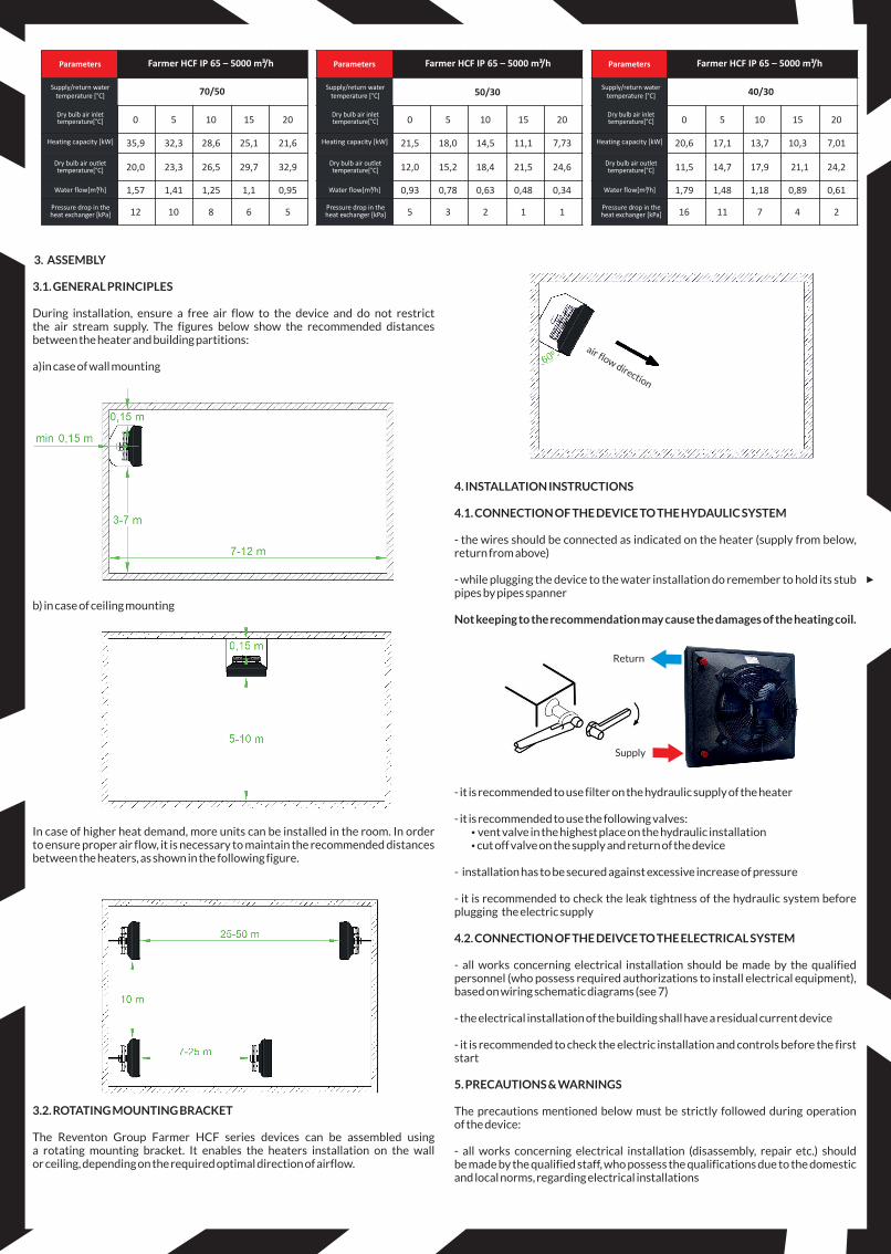
Farmer HCF IP 65 – 5000 m³/h
0 5 10 15 20
50,2 46,4 42,6 38,9 35,3
27,9 31,3 34,6 37,8 41,1
2,21 2,04 1,88 1,71 1,56
21 18 16 13 11
90/70
0 5 10 15 20
43,1 39,3 35,6 32,0 28,5
24,0 27,3 30,6 33,8 37,0
1,89 1,73 1,57 1,41 1,25
16 14 11 9 8
FARMER HCF IP54-3S – 3 stage 4000 m3/h FARMER HCF IP54-3S – 3 stage 4000 m3/h
FARMER HCF IP54-3S – 3 stage 4000 m3/h
80/60 90/70120/90
120/90
40/30 50/30
FARMER HCF IP54-3S – 3 stage 4000 m3/h FARMER HCF IP54-3S – 3 stage 4000 m3/h
Farmer HCF IP 65 – 5000 m³/h
80/60
Farmer HCF IP 65 – 5000 m³/h
0 5 10 15 20
19,1 16,0 12,9 9,92 6,92
13,3 16,3 19,3 22,3 25,2
0,83 0,69 0,56 0,43 0,30
Parameters
Supply/return water temperature [°C]
Dry bulb air inlettemperature[°C]
Heating capacity [kW]
Dry bulb air outlet temperature[°C]
Water flow[m³/h]
Pressure drop in the heat exchanger [ ]kPa
Parameters
Supply/return water temperature [°C]
Dry bulb air inlettemperature[°C]
Heating capacity [kW]
Dry bulb air outlet temperature[°C]
Water flow[m³/h]
Pressure drop in the heat exchanger [ ]kPa
Parameters
Supply/return water temperature [°C]
Dry bulb air inlettemperature[°C]
Heating capacity [kW]
Dry bulb air outlet temperature[°C]
Water flow[m³/h]
Pressure drop in the heat exchanger [ ]kPa
Parameters
Supply/return water temperature [°C]
Dry bulb air inlettemperature[°C]
Heating capacity [kW]
Dry bulb air outlet temperature[°C]
Water flow[m³/h]
Pressure drop in the heat exchanger [ ]kPa
Parameters
Supply/return water temperature [°C]
Dry bulb air inlettemperature[°C]
Heating capacity [kW]
Dry bulb air outlet temperature[°C]
Water flow[m³/h]
Pressure drop in the heat exchanger [ ]kPa
Parameters
Supply/return water temperature [°C]
Dry bulb air inlettemperature[°C]
Heating capacity [kW]
Dry bulb air outlet temperature[°C]
Water flow[m³/h]
Pressure drop in the heat exchanger [ ]kPa
Parameters
Supply/return water temperature [°C]
Dry bulb air inlettemperature[°C]
Heating capacity [kW]
Dry bulb air outlet temperature[°C]
Water flow[m³/h]
Pressure drop in the heat exchanger [ ]kPa
Parameters
Supply/return water temperature [°C]
Dry bulb air inlettemperature[°C]
Heating capacity [kW]
Dry bulb air outlet temperature[°C]
Water flow[m³/h]
Pressure drop in the heat exchanger [ ]kPa
Parameters
Supply/return water temperature [°C]
Dry bulb air inlettemperature[°C]
Heating capacity [kW]
Dry bulb air outlet temperature[°C]
Water flow[m³/h]
Pressure drop in the heat exchanger [ ]kPa
Supply
Return
air flow direction
Farmer HCF IP 65 – 5000 m³/h
0 5 10 15 20
35,9 32,3 28,6 25,1 21,6
20,0 23,3 26,5 29,7 32,9
1,57 1,41 1,25 1,1 0,95
12 10 8 6 5
70/50
0 5 10 15 20
21,5 18,0 14,5 11,1 7,73
12,0 15,2 18,4 21,5 24,6
0,93 0,78 0,63 0,48 0,34
5 3 2 1 1
50/30
0 5 10 15 20
20,6 17,1 13,7 10,3 7,01
11,5 14,7 17,9 21,1 24,2
1,79 1,48 1,18 0,89 0,61
16 11 7 4 2
40/30
Farmer HCF IP 65 – 5000 m³/h Farmer HCF IP 65 – 5000 m³/h
3. ASSEMBLY
3.1. GENERAL PRINCIPLES
During installation, ensure a free air flow to the device and do not restrict the air stream supply. The figures below show the recommended distances between the heater and building partitions:
a)in case of wall mounting
b) in case of ceiling mounting
In case of higher heat demand, more units can be installed in the room. In order to ensure proper air flow, it is necessary to maintain the recommended distances between the heaters, as shown in the following figure.
3.2. ROTATING MOUNTING BRACKET
The Reventon Group Farmer HCF series devices can be assembled using a rotating mounting bracket. It enables the heaters installation on the wall or ceiling, depending on the required optimal direction of airflow.
4. INSTALLATION INSTRUCTIONS
4.1. CONNECTION OF THE DEVICE TO THE HYDAULIC SYSTEM
- the wires should be connected as indicated on the heater (supply from below, return from above)
- while plugging the device to the water installation do remember to hold its stub pipes by pipes spanner
Not keeping to the recommendation may cause the damages of the heating coil.
- it is recommended to use filter on the hydraulic supply of the heater
- it is recommended to use the following valves:źvent valve in the highest place on the hydraulic installationź cut off valve on the supply and return of the device
- installation has to be secured against excessive increase of pressure
- it is recommended to check the leak tightness of the hydraulic system before plugging the electric supply
4.2. CONNECTION OF THE DEIVCE TO THE ELECTRICAL SYSTEM
- all works concerning electrical installation should be made by the qualified personnel (who possess required authorizations to install electrical equipment), based on wiring schematic diagrams (see 7)
- the electrical installation of the building shall have a residual current device
- it is recommended to check the electric installation and controls before the first start
5. PRECAUTIONS & WARNINGS
The precautions mentioned below must be strictly followed during operation of the device:
- all works concerning electrical installation (disassembly, repair etc.) should be made by the qualified staff, who possess the qualifications due to the domestic and local norms, regarding electrical installations
Parameters
Supply/return water temperature [°C]
Dry bulb air inlettemperature[°C]
Heating capacity [kW]
Dry bulb air outlet temperature[°C]
Water flow[m³/h]
Pressure drop in the heat exchanger [ ]kPa
Parameters
Supply/return water temperature [°C]
Dry bulb air inlettemperature[°C]
Heating capacity [kW]
Dry bulb air outlet temperature[°C]
Water flow[m³/h]
Pressure drop in the heat exchanger [ ]kPa
Parameters
Supply/return water temperature [°C]
Dry bulb air inlettemperature[°C]
Heating capacity [kW]
Dry bulb air outlet temperature[°C]
Water flow[m³/h]
Pressure drop in the heat exchanger [ ]kPa
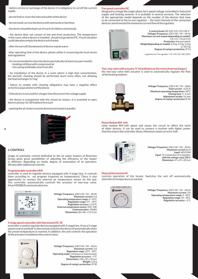
Fan speed controller HC
Two-way valve with actuator ¾” (installation on the return from exchanger)
Manual thermostat HC
designed to change the single-phase fan's speed voltage controlled in industrial supply and heating systems. It is available in several versions. The selection of the appropriate model depends on the number of the devices that have to be connected to the to one regulator – the total intensity of the connected devices cannot exceed the maximum current flow of the regulator.
5 control levels: 80-105-135-170-230 V * Voltage/ Frequency: 230 V AC / 50 – 60 Hz
Maximum current output (depending on model): 3 A, 5 A, 7 A lub 14 A
Protection: thermal switch Weight(depending on model): 2,5 kg, 4,5 kg, 5,5 kg
or 10,5 kg Degree of casing's protection: IP 54
* regulation for 3 A regulator: 115-135-155-180-230 V
the two-way valve with actuator is used to automatically regulate the flow of the heating medium.
Voltage/ Frequency: 230 V AC / 50 – 60HzTotal current: <0,25 A
Maximum operating temperature: 60ºC Closing time: 5 - 6 min
Adjustment stroke: 3,6 mm Degree of casing's protection:IP 40
relay module RM-16A opens and closes the circuit to affect the work of other devices. It can be used to connect a receiver with higher power than the relay in the controller allows. Maximum rated current is 16A.
Voltage/ Frequency: 230 V AC / 50 – 60 Hz Maximum current:16 A
Input: NO/COMInput: SL Connection of a regulator
with the voltage relay 230 VDimension: 47 x 47 x 20 mm
controls operation of the heater. Switches the unit off automatically when the set temperature is reached.
Voltage/ Frequency: 230 V AC / 50 – 60 Hz Maximum current: 3 A
Operating temperature range: 0 - 40°C Regulation range: 10 - 30°C
Regulation accuracy: <1°C
Relay Module RM-16A
- before service or exchange of the device it is obligatory to cut off the current supply.
- do not limit or cover the inlet and outlet of the device
- do not install, service the device with wet hands or barefoot
- the device should be kept out of reach of children and animals
- the device does not consist of the anti-frost protection. The temperature in the room, where device is installed, should not go below 0°C. If such situation could take place empty the device out of water
- after the turn off, the elements of device may be warm
-after operating time of the device, please utilize it concerning the local norms and regulations
- it is recommended to clean the device periodically (at least once per month):ź heating coil blow with compressed airź fan casing and blades clean from dirt
- for installation of the device in a room where is high dust concentration, the periodic cleaning should be performed much more often, not allowing the heat exchanger to 'clog’
- failure to comply with cleaning obligations may have a negative effect on technical parameters of the device
- if the device is not used for a longer time disconnect the voltage supply
- the device is transported with the closed air stators. It is essential to open them in at least for 30 % before first start
- opening the air stators must be done by two hands in parallel
6. CONTROLS
Usage of automatic control dedicated to the air water heaters of Reventon Group gives great possibilities of adjusting the efficiency of the heater in different, depending on needs, degree of automation of its operation. We also offer additional controls:
controller is used to regulate devices equipped with 3-stage fans. It controls them according to set program (required air temperature). There is also opportunity to connect the external air temperature sensor (in the set). The controller automatically controls the actuator of two-way valve. It has MODBUS communication too.
Voltage/ Frequency: 230 V AC / 50 – 60 Hz Maximum current: 5 A
Operating temperature range: 0 - 45°C Regulation range: 5°C - 35°C
Regulation accuracy: ± 0,5°C External temperature sensor: NTC 10K
Communication: RS485 Dimensions: 86 x 86 x 13,3 mm
controller is used to regulate devices equipped with 3-stage fans. It has a 3-stage speed control and built-in thermostat switches the device of automatically when the preset temperature is reached. In addition, the unit controls the operation of the actuators installed on the control valve.
Voltage/ Frequency: 230 V AC / 50 – 60 Hz Maximum current: 3 A
Regulation range: 10°C - 30°C Operating mode: continious or thermostatic
Regulation accuracy: <1°C Dimensions: 130 x 85 x 40 mm
Weight: 210 g Degree of casing's protection: IP 30
Programmable controller HMI
3-stage speed controller with thermostat HC-3S
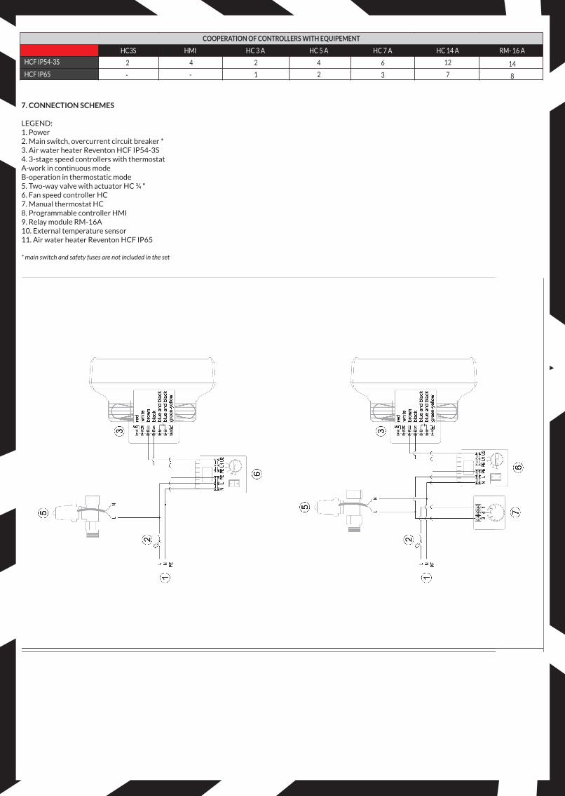
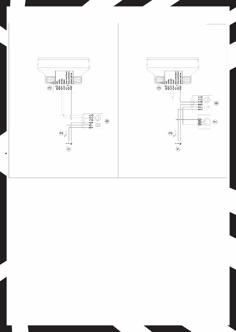
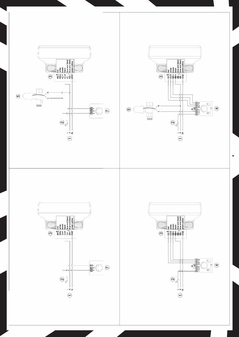
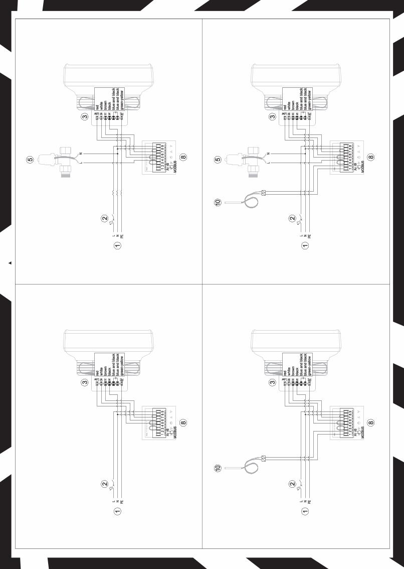
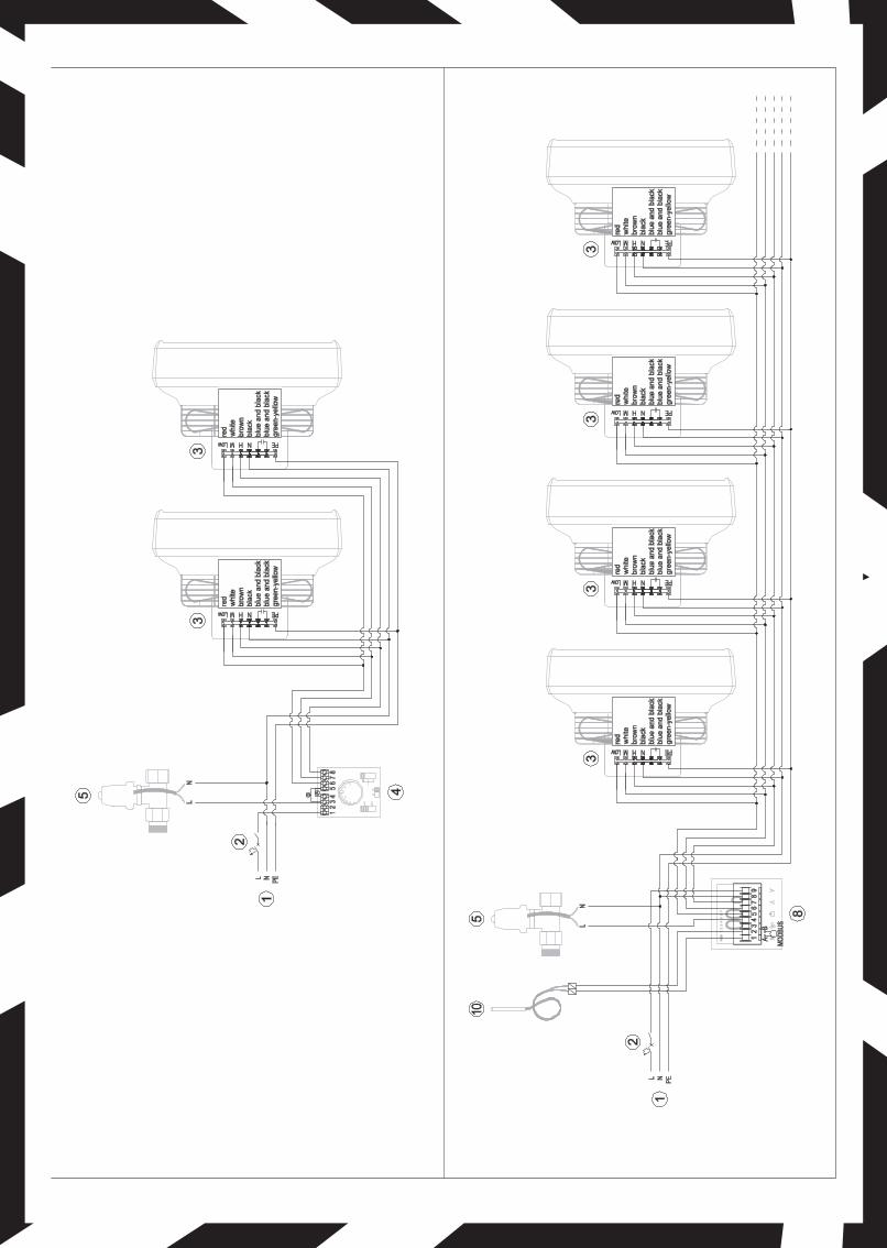
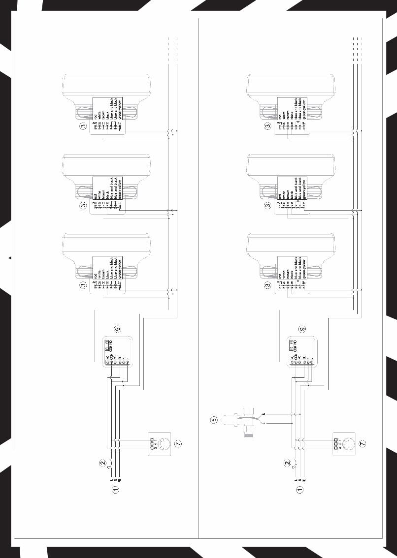
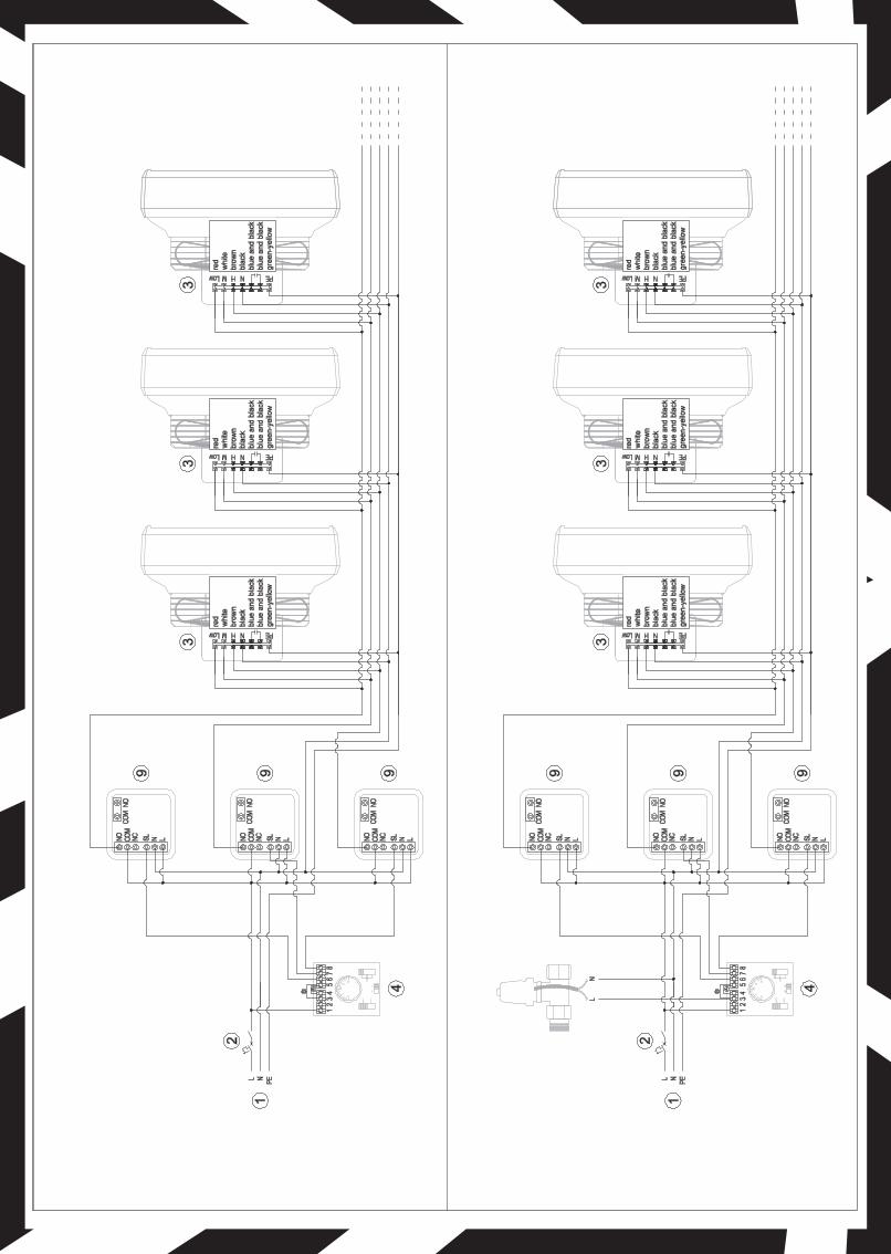
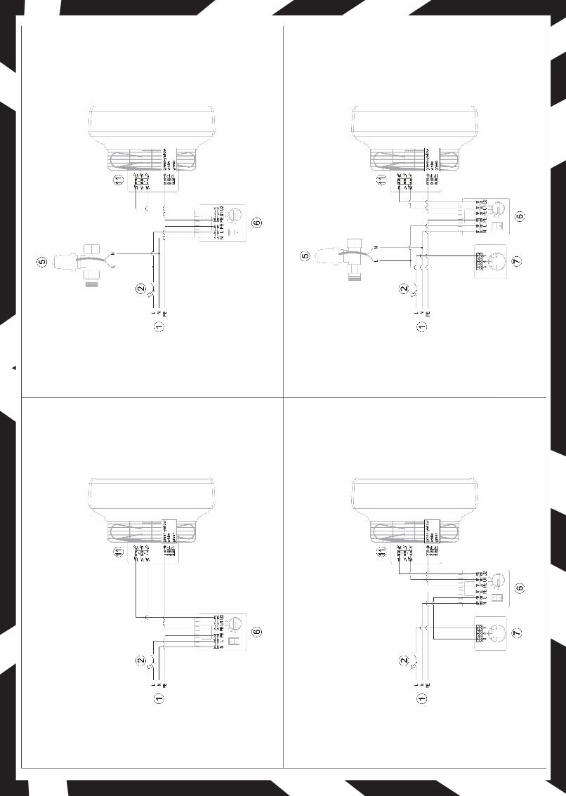
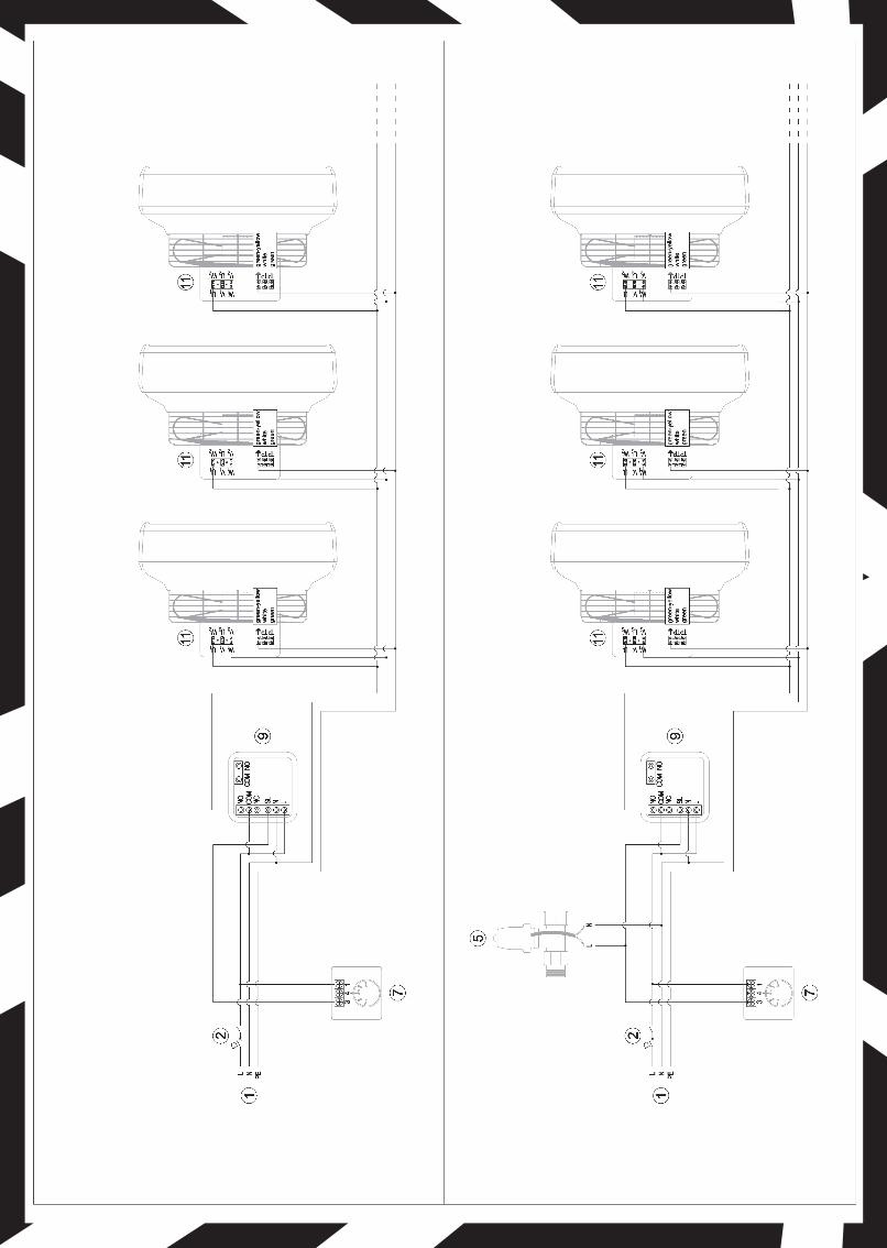
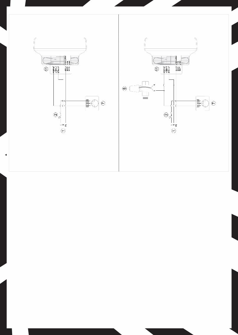
7. CONNECTION SCHEMES
LEGEND:1. Power2. Main switch, overcurrent circuit breaker *3. Air water heater Reventon HCF IP54-3S4. 3-stage speed controllers with thermostatA-work in continuous modeB-operation in thermostatic mode5. Two-way valve with actuator HC ¾ "6. Fan speed controller HC7. Manual thermostat HC8. Programmable controller HMI9. Relay module RM-16A10. External temperature sensor11. Air water heater Reventon HCF IP65
* main switch and safety fuses are not included in the set
HC 3 A HC 5 A HC 7 A
2
1
4
2
6
3
HCF IP54-3S
HCF IP65
HMIHC3S
2
-
4
-
HC 14 A RM- 16 A
12
7
14
8
COOPERATION OF CONTROLLERS WITH EQUIPEMENT
8. TERMS OF WARRANTY
I.Reventon Group Sp. z o.o. [Ltd.] 3B Montazowa Street , 43-300 Bielsko-Biała,Poland, is the producer of the Reventon Group brand. The warranty concerns the following devices and it is valid for 2 (two) years:
- air water heater HCF IP54-3S- air water heater HCF IP65
II. Warranty is valid in the European Union.
III. The terms of warranty are valid from purchasing the device (the date issuing a document confirming the purchase of the device) but not further than 30 (thirty) months from leaving the producer’s warehouse.
IV. Reventon receives the inoperative device or its components, and then sends back the repaired or replaced product (component) free of charge with in 14 working days.
V. In the exceptional cases, the manufacturer reserves the right to extend the time limit for examination of warranty, especially if the defect is not permanent and its determination requires a longer period of time. Any such extension must be notified by the manufacturer beforethe end of the 14th day (working).
VI. Warranty does not cover the parts of the device subject to normal maintenance and the cases as below:
a) mechanical damage of the product
b) defects and damages through
- improper storage or transportation
- improper use or maintenance not in accordance with the instructions
- using the device in the improper conditions (too high humidity, too high or too low temperature, impact of the surrounding, sun etc.)
- modified equipment that has been modified or repaired without written agreement of the producer
- connecting additional equipment, which is not recommended by the producer or inconsistent with the technical documentation
- improper power supply
c) elements which wear and tear such as discolor or using
If there is any of the above, you will be charged for transport and / or repairs.
VII. Any changes in the Warranty Terms, improper use of the product (careless handling, exposure to liquids, moisture, corrosion), as well as traces of self-repairing (except for the Reventon Group manufacturer's service), alterations or attempts to make structural changes to the product, (revealed during the performance of warranty service), makes warranty not valid.
VIII. To obtain the service it is needed to send to the producer warranty card with the signature, document confirming the purchase, (copy of the invoice) and correctly filled the warranty form.
IX. Not following to any of warranty regulations makes the warranty not valid.
X. All correspondence, returns, complains should be send to the following address: Reventon Group Sp. z o.o. 3B Montazowa Street, 43-300 Bielsko-Biała, Poland or e-mail: [email protected]
The producer reserves the rights to make changes to the technical documentation without previous notice.
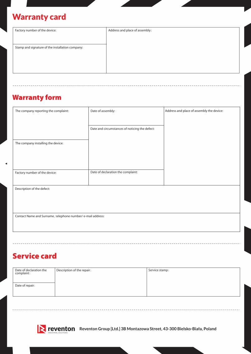
Warranty card
Reventon Group [Ltd.] 3B Montazowa Street, 43-300 Bielsko-Biała, Poland
:
:
: :
:

Reventon Group [Ltd.] 3B Montazowa Street, 43-300 Bielsko-Biała, Poland, www.reventongroup.eu