FAN-DS-2 August 2000 Model Q Fans Sizes 16 through 60 ... · Sizes 16 through 60 FAN-DS-2 August...
56
Super Q II Fans Sizes 16 through 44 Model Q ™ Fans Sizes 16 through 60 FAN-DS-2 August 2000 FAN-DS-2 Super Q II Fans Sizes 16 through 44 Model Q Fans Sizes 16 through 60
Transcript of FAN-DS-2 August 2000 Model Q Fans Sizes 16 through 60 ... · Sizes 16 through 60 FAN-DS-2 August...
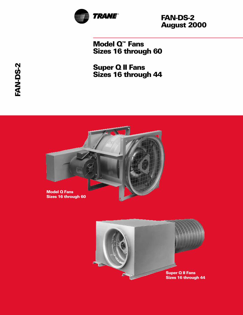
Super Q II FansSizes 16 through 44
Model Q™ FansSizes 16 through 60
FAN-DS-2August 2000
FAN
-DS
-2
Super Q II FansSizes 16 through 44
Model Q FansSizes 16 through 60

2
Featuresand Benefits
©American Standard Inc. 2000
Q FanThe Model Q™ fan is a quiet, airfoil, in-line fan specifically designed for airconditioning applications. This highlyrefined axial flow fan is available in 13sizes from 1,000 through 80,000 cfm.Small and compact, the Q fan hasproven to be the ideal air movingdevice for standalone applications andalso for custom air handling units. Itcan be used for supply, return andexhaust systems.
Available in arrangement 1 (for floormounting of larger units with heaviermotors) and arrangement 9 (horizontalor vertical mounting), it can be selectedin class 1, 2 and 3. Arrangement 9permits factory mounting of the motoron top, bottom, or either side of the fan— see below.
Benefits
• The Q (Quiet) FanThe Trane Model Q fan generates lesslow frequency noise (more difficult toattenuate) than any other type of fan inthe HVAC industry. Sound levelcomparisons show common vaneaxialfans produce up to 23 db higher soundlevels than the Model Q — significantin industrial applications. Being quieterthan centrifugal fans allows forinstallations closer to buildingoccupants.
• Saves Mechanical Room SpaceThe compact quiet Q fan saves floorspace, which reduces system first cost.
• Easy To InstallRigging and installation is so muchquicker and easier that total installedcost savings are typically five percentor more.
• Low MaintenanceBelt-driven with fixed blades, Model Qfan has very few moving parts. Thisdesign results in exceptionally lowmaintenance requirements. No fanteardowns need be scheduled. In fact,Q fans installed 25 years ago are stilloperating just as quietly as when theywere installed.
Discharge End View
Arrangement 9 Arrangement 1
AMCA Licensed RatingsThe Trane Company certifies that theModel Q fans shown herein arelicensed to bear the AMCA Seal. Theratings shown are based on tests andprocedures performed in accordancewith AMCA Publication 211 andcomply with the requirements of theAMCA Certified Ratings Program.
• Flexible InstallationThe Model Q arrangement 9 can be setin any position, for horizontaldischarge, angled discharge andvertical discharge either upblast ordownflow. The only limitations placedon this arrangement are those dictatedby good fan installation practice.
• Motor slide rails and drive guard arestandard, at no extra cost.

3
Contents
Q Fan Accessories• Inlet flange — for simplified, rigid
connection of ductwork to inlet end offan
• Inlet screen — safety accessorymounted to fan inlet. Heavy, platedsteel wireNote: inlet screen and inlet flange aremutually exclusive.
• Inlet vanes — mechanically modulatefan capacity
• Inlet bellmouth — used with unductedor plenum applications. Improves airflow and reduces noise.
• Inlet silencer (long or short) — flexconnected to Q fan
• Outlet flange — for simplified, rigidconnection of ductwork to outlet end offan
• Outlet screen — safety accessorymounted to fan outlet. Heavy, platedsteel wireNote: outlet screen and outlet flangeare mutually exclusive.
• Outlet duct diffuser (equalizer) —makes fan outlet diameter equal to inletdiameter
• Outlet flow stabilization screen — smallmesh outlet screen. Helps offset effectof poor outlet airflow conditions
• Outlet silencer (short or long) — flexconnected to Q fan
• Vertical mounting legs — used witharrangement 9 for vertical dischargefloor and ceiling mounted
• Isolators — to eliminate vibrations forfloor, ceiling and vertical installations
• Special coatings — to protect againstalkyds, acids and corrosiveenvironments
• Access door — available on sizes 49, 54and 60 for easier service
• Drain — recommended to drain off thecondensate where moisture-laden air isexhausted
• Copper grease lines — plastic lines arestandard
• Double acoustic enhancement —insulation and perforated sheet metalto attenuate radiated sound
• Fan insulation — self-adhesive foam,applied on the outside of the fan shellto protect against moisture
• Variable frequency inverter balancingand reinforcement (frequency inverterby others). This option requiresconstant pitch drives. Model Q Fan — Arrangement 9
Features and Benefits 2
Model Number Description 12
Application Considerations 13
Selection Procedure 21
Performance Data 22
Dimensional Data and Weights 48
Mechanical Specifications 54

4
This chart shows a typical NC levelcomparison between commonvaneaxials, tubular centrifugals, airfoilcentrifugals and the Trane Model Q™
compact fan. The shaded arearepresents range of vaneaxials tested.
Trane Model Q fans require up to85 percent less cubic space than airfoilcentrifugal fans and 40 percent lessthan common vaneaxials of equivalentinstalled sound level. Floor spacesavings can be as much as 65 percentwhen compared to the commonvaneaxial and airfoil centrifugal and40 percent when compared to tubularcentrifugals.
Vaneaxial Fan
Airfoil Centrifugal Fan
Tubular Centrifugal Fan
Trane Model Q Compact Fan
Featuresand Benefits

5
Featuresand Benefits
Super Q II PlusMore than twenty years after theintroduction of the Model Q™, it stillretains its reputation as one of thequietest HVAC fans in the world. Thistradition of excellence continues withthe introduction of a new Q fanacoustical enclosure and duct silencerso effective and so compact that wenamed it the Super Q II.
Super Q II FanAvailable with Model Q fans from 1,000to 43,000 cfm, the Super Q II enclosureinhibits radiated fan and motor noisefrom entering the surrounding space. Itinternally isolates the fan on highdeflection spring isolators so ductworkcan be connected directly to theenclosure. It is uniquely designed to befloor or ceiling mounted with ease.
Although the Model Q needs very littlemaintenance, future maintenancerequirements were considered bySuper Q II designers. Every unit has thebearing grease lines extended throughthe casing and every unit has two fullsize access panels that providecomplete access to all internalcomponents.
Variable Air Volume CompatibleThe Super Q fan is modulated for VAVwith variable frequency drives (byothers), not with inlet vanes. Variablespeed inverter fan modulation offersexceptional energy saving andexceptionally quiet part load operation.VAV variable speed Q fans arestructurally reinforced to handle theuneven harmonic loadings associatedwith variable speed fan operation. Inaddition, the factory gives variablespeed Q fans a precise, 10-pointbalance to further help assure trouble-free operation. Only constant pitchdrives should be used with variablefrequency inverters.
Super Q II Accessories
• Inlet screen — safety accessorymounted to fan inlet. Heavy, platedsteel wire
• Inlet bellmouth — used with unductedor plenum applications. Improves airflow and reduces noise.
• Inlet silencer (long or short) — rigidconnection to Super Q fan
• Outlet flow stabilization screen — smallmesh outlet screen. Helps offset effectof poor outlet airflow conditions
• Outlet silencer (short or long) — flexconnected to Q fan
• Variable frequency inverter balancingand reinforcement (frequency inverterby others). This option requiresconstant pitch drives.
• Outlet screen — safety accessorymounted to fan outlet. Heavy, platedsteel wire.
Super Q II

6
Featuresand Benefits
Trane Plus Duct SilencerThe Plus option is a high performanceduct silencer. Designed specifically forthe Super Q II and Model Q™, it hasseveral unique features that reduceairborne noise and turbulence toexceptionally low levels. Briefly, thePlus option develops maximum staticregain while simultaneously limitingobjectionable mid and high frequencynoise. The Plus option should be usedwhenever quiet comfort is desiredand the duct system is acousticallyunable to provide it.
Trane’s Plus Silencer providessignificant noise attenuation, up to32 db at 1,000 Hz, without a significantincrease in fan horsepowerrequirements.
Plus Silencer
The modular, component designapproach of the Super Q II air handlingsystem makes it exceptionally wellsuited for renovation, retrofit andreplacement projects. The Super Q II airhandling system components (fan,silencers, filter/coil module, etc.) fitthrough most doors and elevators andcan be easily field-assembled into anysystem configuration (blow-thru, draw-thru, etc.).
By carrying the concept of noise sourceattenuation to its economic maximum,Trane has created a fan system that canmove significant amounts of airwithout creating objectionable lowfrequency rumble. It provides provenacoustical performance with lessdesign risk. In project after project, theTrane Model Q fan has been the key tocreating NC 15 to NC 35 quietcomfort jobs.
Beyond quiet, the Super Q II Plussystem is small and compact. In fact, itis small and quiet enough that it can besuccessfully installed in ceilingplenums. Locating a Super Q II Plus inthe plenum helps reduce and eveneliminate the floor space needed forthe mechanical room.

7
Featuresand Benefits
Low Sound Level, High EfficiencyProvided by Unique AerodynamicFeatures
[7] Hub Streamlining Insulation
[9] Airfoil Vanes (stationary)
[10] Stabilizing Pitch
[4] Airfoil Blade Wheel.
[5] Aerodynamic Pitch
[6] Minimum Tip Clearance[2] Aerodynamic Inlet Bell
[12] End Cone
[8] Exact Blade to Vane Spacing
[11] Precise Divergent Angle Diffuser Discharge Cone
[3] Aerodynamic Inlet Cone
[1] Thin Strut Patented Bearing Support
Precision cast fan wheel and diffuserfor highly efficient aerodynamicperformance. [8]
Precise divergent angle for maximumstatic regain. [11]
Aerodynamic inlet provides smoothairflow. [3]
Note: Call-out numbers shown above are referenced on page 8.

8
Featuresand Benefits
The low sound and high performanceof the Trane Model Q™ fan are achievedby reducing noise-creating, energy-consuming turbulence within the fan.Airflow research and developmenttechniques employed were similar tothose used in perfecting today’s highperformance axial flow jet enginecompressors. The resulting smooth airpath has made the Model Q the firstvaneaxial fan to provide quiet, efficientoperation, suitable for air conditioningduty.
Aerodynamic Air PathA component by component analysisof the Model Q points to 12aerodynamic features which are keysto a smooth air path. Starting at theinlet, the struts [1] of the patentedbearing support are preciselypositioned in relation to the fan blades.Air passing over the struts strikes theblades in a pattern that prevents bladewhine.
The aerodynamically shaped inlet bell[2] and inlet cone [3] provide uniformaxial flow parallel to the fan shaft. Air isdelivered equally to the leading edge ofthe fan blades — no crowding towardthe fan tips.
Air separation is reduced by theprecision cast aluminum airfoil crosssection [4] of the fan blades. Blade pitch[5], using a variable angle of attack inthe radial dimensions, is preciselycontrolled to prevent energy loss.Exceptionally close clearance[6] between the blade tips and housingreduces the eddy currents of fan tiprecirculation. The reinforcing ringrigidizes the housing to maintain the tipclearance. The interior of the fan wheelis insulated to prevent hubstrengthening protrusions from[7] windmilling in the airstream.
A precisely controlled space [8]between the fan blades and diffuservanes is necessary to allow airflow
stabilization ahead of the vanes. Thevanes themselves are precision castaluminum and have an airfoil crosssection [9] and a precise radial pitch[10]. This provides smooth, spiral-freedischarge.
The diffuser section design [11] iscritical. A precisely determineddiffusion angle produces the greatestpossible static regain within theconfines of the fan. An end cone[12) covers the fan drive assembly,thereby reducing the turbulencegenerated by air passing over exposeddrives.
Precise Manufacturing AssuresPerformance — Advancedmanufacturing techniques assure thesame performance characteristics foreach production Model Q fan.
• Fin Struts — The fin struts of thepatented bearing support are preciselypositioned in relation to the fan blade.Air passing over the struts strikes theplate in a pattern that prevents theirritating whine, from blade frequency,which is characteristic of industrialvaneaxials.
• Inlet Bell and Cone — Theaerodynamically shaped inlet bell andinlet cone provide uniform axial flowinto the fan parallel with the fan shaft.Air is delivered equally to the leadingedge of the fan blades. This preventscrowding toward the blade tip.
• Wheel — The wheel consists of 8precision cast blades with a twistedradially projected shape and airfoilcross section. This radial projectionutilizes a variable angle of attack in theradial dimension and prevents radialmovement as the air particles movethrough the wheel.
• Tip Clearance — Close clearancebetween the blade tips and housingreduces eddy currents due to tiprecirculation. The reinforcing ring holdsthe housing in its precise shape tomaintain proper clearance.
• Vane Spacing — Precise spacebetween the fan blades and the diffuservanes is necessary to allow flowstabilization ahead of the vanes. The 29diffuser vanes also have an airfoil crosssection and a twisted, radially projectedshape. This provides smooth, spiral-free air discharge.
• Precision Cast Aluminum Fan andDiffuser — Being cast, blade and vaneshapes are permanently and preciselyfixed. They are not subject tomisalignment or distortion as arewelded, sheet metal forms.
• Diffuser Section — The diffusersection design is critical. A preciselydetermined flare angle at the diffuserend produces the greatest possiblestatic regain within the confines of thefan. Thus, externally mounted diffuseraccessories, common for industrialvaneaxials, are not necessary.
• Hydraulically Expanded Flow-Formed Housing — In this process,the cylindrical housing is drawn to itsfinal form over an expansion die. Themetal, expanded beyond its elasticlimit, permanently retains the precisionform imparted by the die.
• Ductile Weld Technique — Thistechnique is required for the fanhousing seam to guarantee success ofthe expansion forming process. The arcand “puddle” are submerged inmolten flux that shields the weldmaterial from oxidation. This preventsbrittleness and also anneals the weld.The result is a flexible, ductile seamcapable of being drawn and formed —another example of the advancedtechnology used in the Trane ModelQ fan.

9
Featuresand Benefits
The Trane Model Q™ and Super Q IIfans can help you maximize yourbuilding’s usable floor space by usingthem in place of centrifugal fans. Thesmaller the equipment room, the morespace left for tenants, merchandise, etc.
Saving ValuableEquipment Room SpaceReturn or Exhaust ApplicationsFigure F-1 shows a size 44, singlewidth, low pressure airfoil centrifugalfan delivering 20,000 cfm of air.Because of its size and weight, it is floormounted and connected to a return airplenum. In contrast, a 44-inch Model Qfan is used in Figure F-2 instead of acentrifugal fan. Its smaller size andlighter weight permits ceilingsuspension and approximately 75 sq ftof floor space is freed up for other use.
Draw-Thru Supply Application(Small Capacity)The fan system in Figure F-3 is a27-inch, single width, medium pressureairfoil centrifugal fan rated at 9,000 cfm.Even though it is a relatively small fan,it is floor mounted beside the coil bankplenum. Figure F-4 shows a 27-inchModel Q substituted in place of thecentrifugal. The small size and weight,plus the installation flexibility of theModel Q, permits mounting in avertical position on top of the plenum.The space savings is about 25 sq ft.
Figure F-1 Figure F-3
Figure F-2 Figure F-4

10
Featuresand Benefits
Draw-Thru Supply Application(Large Capacity)A 60-inch, single-width, mediumpressure airfoil centrifugal fan is usedin the system illustrated in Figure F-5 tosupply 45,000 cfm of air. This capacitycan be easily achieved by installing apair of 40-inch Model Q™ fans inparallel as shown in Figure F-6. Theresulting floor space savings isapproximately 85 sq ft!
Blow-Thru Supply ApplicationFigure F-7 shows a typical mediumpressure, built-up, blow-thru system.The fan, enclosed in a plenum, is a 33-inch, double width, airfoil centrifugalthat delivers 30,000 cfm of air. Thebulkiness of the plenum is dictated bythe necessary clearances around thefan. To save floor space, a 44-inchModel Q replaces the centrifugal inFigure F-8. The suspended mounting ofthe Model Q frees about 70 sq ft forinstallation of pumps and otherequipment.
Figure F-6 Figure F-8
Figure F-5 Figure F-7

11
Featuresand Benefits
The Trane Model Q™ fan, with all itsprecision and quality, is still a costeffective fan. When all necessarysystem components are considered, itprovides substantial installation costsavings. In addition, its small size andvariable mounting positions allowmore freedom to the designer andinstaller.
First Cost ComparisonsTrue first cost is the total cost of anoperable installation. With the TraneModel Q, this consists of only the fan,drive and isolation. By comparison, theairfoil centrifugal typically requiresthese three components, plus anintegral base. In addition, cost ofisolation for the airfoil is greaterbecause it is typically twice as heavy asthe Model Q.
The common vaneaxial also requiresmore components in mostapplications. Besides the fan, drive andisolation, an inlet bell and diffuser arefrequently necessary to meet catalogedperformance. A sound attenuator isalso required to reduce noise to a levelequivalent to a Model Q fan withoutattenuation.
Reduce Installed CostBy Up To 20 PercentLower Installation CostsThe Trane Model Q fan has fewercomponents to install and theadvantage of lighter weight. With onlyhalf the weight of airfoil and tubularcentrifugals, it requires less manpowerfor rigging and setting the fan in place.The result is reduced labor, withcorresponding dollar savings on thetypical job.
Lighter weight also reduces inertia padrequirements. With the Model Q, a padhas to be considered only on large
Table F-1 — Total Installed Cost ComparisonStandard Trane Tubular
Item Required Centrifugal Model Q Centrifugal Vaneaxial
First Cost Requirement
Fan X X X X
Belt Guard X X X
Integral Base X
Inlet Bell X
Attenuation X
Spring Isolators X X X X
Installation Cost Requirements
Rigging X X X X
Install Attenuation X
Mount Motor (Etc.) X X
Install Isolation X X X X
Average Total Installed Cost X –5 +5 +15Comparison is based on equal size fans of similar capacities. The airfoil centrifugal fan is used as base (100%) forcomparative purposes. Figures are based on estimates by experienced installing contractors.
Arrangement 9 Trane Model Q fanrequires purchase of motor, motorrails, belt guard and isolation inaddition to the basic fan.
Arrangement 3 airfoil centrifugal fanrequires purchase of motor, beltguard, motor slide rail, isolation andsubbase in addition to basic fan.
Class III fans. Airfoil and tubularcentrifugals, because of greater weight,often require pads for Class I and II tominimize the effect imposed by normalvibration.
Combined Saving SignificantA comparison of average total installedcost is shown in Table F-1. Average costfigures were developed based onestimates by experienced installingcontractors. In all cases, the TraneModel Q represents a significantsavings.

12
ModelNumberDescription
Valid Select-Prod. ableCat. Item Description
CYCLE QSE E-cycle 16-44 arr 9 cl 1&2w/o mtr mtd
QSE1 E-cycle 16-44 arr 9 cl1&2w/mtr mtd
QSQ Q-cycle 16-44 arr 9 cl 1,2&3MTO Std cycle 16-44 arr 1&9
cl 1,2&3 & SQ2MTO1 Std cycle 16-44 arr 1&9
w/unit coatingMTO2 Std cycle 49-60 arr 9 cl 1&2MTO3 Std cycle 49-60 arr 9
w/unit coating
MODEL QFNA Q (Quiet) fan
TYPE SQ2 Super Q2 fanQFAN Q fan
SIZE 16 Fan size 16” (400 mm)19 Fan size 19” (475 mm)21 Fan size 21” (525 mm)24 Fan size 24” (600 mm)27 Fan size 27” (675 mm)30 Fan size 30” (750 mm)33 Fan size 33” (825 mm)36 Fan size 36” (900 mm)40 Fan size 40” (1000 mm)44 Fan size 44” (1100 mm)49 Fan size 49” (1225 mm)54 Fan size 54” (1350 mm)60 Fan size 60” (1500 mm)
ARRG 9 Arrangement 9 fan1 Arrangement 1 fan
CLASS 1 Class 1 fan2 Class 2 fan3 Class 3 fan
UORT UP Upblast dischargeDOWN Downblast dischargeH Horizontal discharge
MTRS TT Trane supplied motor &Trane mounted
FT Field supplied motor &Trane mounted
TF Trane supplied motor &field mounted
FF Field supplied motor &field •mounted
TRES WB Thrust restraints WB(direct ship)
NONE No thrust restraints
DUCT YES Duct canvas
WBAL FACT Q fan inverter factorybalancing
FIELD Inverter ready balanced bycustomer
Valid Select-Prod. ableCat. Item Description
MTHP 1 Motor hp 1 (.7 kW)1.5 Motor hp 1.5 (1 kW)2 Motor hp 2 (1.5 kW)3 Motor hp 3 (2 kW)5 Motor hp 5 (4 kW)7.5 Motor hp 7.5 (5.5 kW)10 Motor hp 10 (7 kW)15 Motor hp 15 (11 kW)20 Motor hp 20 (15 kW)25 Motor hp 25 (18 kW)30 Motor hp 30 (22 kW)40 Motor hp 40 (30 kW)50 Motor hp 50 (37 kW)60 Motor hp 60 (44 kW)75 Motor hp 75 (56 kW)
MTYP HEOP18ODP High eff mtr 1800 rpm1S/1W
ODP12 ODP High eff mtr 1800/1200 rpm 2S/2W
ODP91 ODP High eff mtr 1800/900 rpm 2S/1W
ODP92 ODP High eff mtr 1800/900 rpm 2S/2W
PHOP18ODP Prem Hi E+3 mtr1800 rpm 1S/1W
HETE18 TEFC High eff mtr 1800 rpm1S/1W
PHTE18 TEFC Prem Hi E+3 mtr1800 rpm 1S/1W
VOLT 200 200 Volt 60 hertz 3 ph motor208 208 Volt 60 hertz 3 ph motor230 230 Volt 60 hertz 3 ph motor460 460 Volt 60 hertz 3 ph motor575 575 Volt 60 hertz 3 ph motor
MOLO R Motor location right handdrive
L Motor location left handdrive
T Motor location top driveB Motor location bottom drive
GRSL N Nylon grease linesC Copper grease lines
DTYP C1.2 Constant pitch drive with1.2 DSFT
C1.4 Constant pitch drive with1.4 DSFT
C1.5 Constant pitch drive with1.5 DSFT
V1.2 Variable pitch drive with1.2 DSFT
V1.4 Variable pitch drive with1.4 DSFT
V1.5 Variable pitch drive with1.5 DSFT
Valid Select-Prod. ableCat. Item Description
INSL F Fan insulationFA Fan and accessories
insulation
ENHA DBLE Double acousticenhancement
COAT BPI Baked phenolic (heresite)inside
BPIO Baked phenolic (heresite)in/outside
EI Epoxy insideEIO Epoxy inside/outsideEPI Epoxy phenolic
(2 components) insideEPIO Epoxy phenolic (2
components) inside/outsideEPADI Epoxy phenolic (air dry
heresite) insideEPADIO Epoxy phenolic (air dry
heresite) inside/outsidePEI Polyester (sanitile) insidePEIO Polyester (sanitile) inside/
outside
IOPT IB Inlet bellIF Inlet flangeISC Inlet screenIBSC Inlet bell with inlet screenSH Inlet silencer shortL Inlet silencer longIV Inlet vanesNONE No inlet options
OOPT OFLG Outlet flangeOSCN Outlet screenODEQ Outlet duct equalizerODOF Outlet duct equalizer w/
outlet flangeSH Outlet silencer shortL Outlet silencer longNONE No outlet options
ISOL SLF Free standing spring floorisolators
C Housed spring floor isolatorsND Dbl deflection neoprene
floor isolatorsRSL Spring rail floor isolatorsMSL Steel base w/spring floor isolKSL Concrete inertia base w/spring
floor isolatorsHD Dbl deflection neoprene
ceiling isolatorsHS Spring ceiling isolatorsDNHS Spring & neoprene ceiling isolWR Neoprene wall isolators
ADOR MS Access door motor sideOS Access door opp. motor side9R Access door 90° right of motor9L Access door 90° left of motor
DRAN YES Drain
MTGL IL Inlet mounting legsOL Outlet mounting legs
13
ApplicationConsiderations
This section assists the systemdesigner in application and control ofTrane Q and Super Q II fans.Satisfactory distribution of conditionedair requires a properly chosen fan anda well designed duct system.
Abbreviationssp ...... static pressure (in. of water)vp ...... velocity pressure (in. of water)tp ....... total pressure (in. of water)ov ...... outlet velocity (ft per minute)rpm ... fan speed (revolutions per min.)bhp ... brake horsepowerp ........ air density (lbs/ft3)db ...... decibel (sound power or sound
pressure level)cps .... cycles per secondcfm .... cubic feet of air per min. at any
densityscfm .. cubic feet per min. of standard air
clean, dry air with a density of 0.075 lbs/ft3 at 70 F and a barometer reading of 29.92- inches Hg)
The SystemAn air system may consist of a fan,ductwork, air control dampers, coolingcoils, heating coils, filters, diffusers,noise attenuation, turning vanes, etc.The fan is the component in the systemwhich provides energy to the airstreamto overcome the resistance to flow ofthe other components.
System Component LossesEvery system has a combinedresistance to flow which is usuallydifferent from every other system andis dependent upon the individualcomponents in the system. Thedetermination of the “pressure loss” or“resistance to flow,” for the individualcomponents can be obtained from thecomponent manufacturers. Thedetermination of pressure losses forductwork and branch piping design iswell documented in standardhandbooks such as the ASHRAEHandbook of Fundamentals.
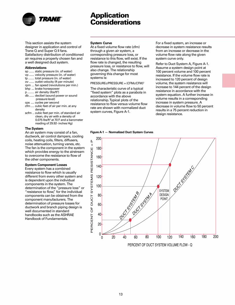
System CurveAt a fixed volume flow rate (cfm)through a given air system, acorresponding pressure loss, orresistance to this flow, will exist. If theflow rate is changed, the resultingpressure loss, or resistance to flow, willalso change. The relationshipgoverning this change for mostsystems is:
PRESSUREc/PRESSURE = (CFMc/CFM)2
The characteristic curve of a typical“fixed system” plots as a parabola inaccordance with the aboverelationship. Typical plots of theresistance to flow versus volume flowrate are shown with normalized ductsystem curves, Figure A-1.
For a fixed system, an increase ordecrease in system resistance resultsfrom an increase or decrease in thevolume flow rate along the givensystem curve only.
Refer to Duct System A, Figure A-1.Assume a system design point at100 percent volume and 100 percentresistance. If the volume flow rate isincreased to 120 percent of designvolume, the system resistance willincrease to 144 percent of the designresistance in accordance with thesystem equation. A further increase involume results in a correspondingincrease in system pressure. Adecrease in volume flow to 50 percentresults in a 75 percent reduction indesign resistance.
Figure A-1 — Normalized Duct System Curves

14
ApplicationConsiderations
Performance Data DeterminationThe fan performance section of thiscatalog contains a fan performancetable and fan curve for each fan size.
The performance data contained in thiscatalog was calculated from testsconducted in accordance with AMCAStandard 210 Laboratory Methods ofTesting Fans for Rating.
The AMCA test procedure uses anopen inlet and 10 wheel diameters ofstraight discharge ductwork to assuremaximum static regain. The fan isdirect driven by a dynamometer.
The fan performance tables in thiscatalog are based upon standard air:0.075 lbs/ft3 (70 F, barometric pressure29.92-inches Hg).
Fan Performance CurvesA fan performance curve is a graphicalpresentation of the performance of afan. Usually it covers the entire rangefrom free delivery (wide open cfm, noobstruction to flow) to no delivery(blocked tight, an airtight system withno air flowing).
The point of intersection of the systemcurve and the fan performance curvedetermines the point of operation andactual flow volume. If the systemresistance has been accuratelydetermined and the fan properlyselected, their performance curves willintersect at the design flow rate. Referto Figure A-2. The normalized DuctSystem A from Figure A-1 has beenplotted with a normalized fanperformance curve.
Temperature and Altitude CorrectionsThe fan performance values in thetables and curves of this catalog arebased on standard air (.075 lbs/ft3). Ifthe airflow requirement for a particularjob is stated in terms of nonstandardair, a density correction needs to bemade before selecting the fan. It isimportant to also note that most airfriction charts for ducts, filters, coils,etc. are also based on standard air andcorrections must be made to determineproper losses at other conditions.
Figure A-3 illustrates the ratio of airdensities to standard air at varioustemperatures and elevations. A Q fan isdesigned for operation between -20 Fand 150 F only.
Figure A-2 — Point of Operation — Interaction of the System Curve and the Fan Performance Curve
Figure A-3 — Air Density Corrections

15
The following is the procedure to usewhen selecting a fan for elevations andtemperatures other than standard:1Determine the air density fromFigure A-3.2Divide static pressure at the non-standard condition by the air densityratio.3Use the actual cfm and corrected staticpressure to determine rpm and bhpfrom the fan performance tables.4The rpm is correct as selected.5The bhp must be multiplied by the airdensity ratio determined in step one toget the actual operating bhp.
Option and Installation Kt CorrectionsSystem effect losses due to less thanideal inlet or outlet configuration can beexpressed in terms of velocity pressureby the following expression:
Inlet SP Loss =
Kti ( Inlet Velocity )2
4005
Where Kti =Inlet Option Kt + Inlet Installation KtOutlet SP Loss =
Kto (Outlet Velocity)2
4005
Where Kto = Outlet Option Kt + OutletInstallation Kt
Kt is the loss factor for the inlet ordischarge condition being considered.
It is necessary to add all of the staticpressure loss determined from theabove equation to the componentstatic pressure to determine the pointof duty static pressure for selection ofthe fan.
Fan Option Kt CorrectionsThe fan static pressure should beadjusted for fan options. Optionpressure drops are documented as Ktlosses and are handled the same wayas installation Kt effects (losses). UseTable A-1, Q Fan/Super Q II Fan Ktcorrections, to determine the Kt values.Add these values to any installation Ktvalues. Use the result to select the fan.
Table A-2 — Q Fan/Super Q II Fan Option Kt CorrectionsSuper Q II Pressure
Options Use Q-Fan Fan Drop (Kt)Inlet Flange Connects to bolted inlet duct X 0Inlet Bellmouth* Reduces Unducted Inlet Kt X X -.1Inlet Plus Silencer Reduces inlet noise X X +.1Inlet Screen Protects Unducted Inlets X X +.1Outlet Screen Protects Unducted Outlets X +.5Outlet Flange Connects to bolted outlet duct X 0Outlet Equalizer (Diffuser) Improves SE X 0Outlet Plus Silencer Reduces Outlet Noise X X +.1Outlet Flow Stabilization Screen Reduces Outlet swirl X X +.8Outlet Backdraft Damper Isolates fan from duct Special Special +.5Frequency Drive Modulation Modulates Q Fan quietly Special Special 0Belt Guard Protects drives/belts X 0Motor Rails Allows motor to be mounted X Included 0Standard Isolators Isolates fan X Included 0Seismic Isolators Isolates fan X Special 0*Note: Bellmouth effect included in unducted installation Kt correction. Fan sizes 49 through 60 fan curves are cataloged with inlet bells. For unducted inlets without bells on size 49 through 60 fans add .1 to the inlet Kt given above.
Inlet vane losses are covered in the Selection Procedure with air density corrections (page 20).
ApplicationConsiderations
Table A-1 — Q Fan/Super Q II Fan Installation Kt Corrections
Unducted (Plenum) Inlet*Draw-Thru Type Design 0.0
Ducted InletTurn > 3 Dia Upstream -1.0Turn 2 Dia Upstream +.8Turn 1 Dia Upstream +1.3Turn < 1 Dia Upstream
Not Recommended
Unducted OutletBlow-Thru Type Design +.8
Ducted OutletTurn > 2 Dia Downstream 0.0Turn 1 Dia Downstream +1.3Turn < 1 Dia Downstream
Not Recommended
Figure A-4 — Ducted Turns Near Q Fan

16
ApplicationConsiderations
Q and Super Q II Fan Modulation —AC Inverter Capacity ControlQ fans and Super Q II fans can bemodulated with AC frequency drives.The Trane Company recommendsMagnetek low noise inverter drives andCentury high efficiency motors foroptimum modulation performance.
Operating the Q or Super Q II fan on ACfrequency drives requires the Q fan tobe strengthened and balanced in thefactory. This option “beefs up” themechanical bracing of the Q fan inletbearing assembly and calls for aprecision factory balance. Precisionbalancing covers 10 operating pointson the system curve from 10 percentload to full load.
Minimum cfm with AC inverters —Above 1.5” static pressure, theminimum cfm is the surge (do notselect) line. Below 1.5” static pressure,it is 1000 cfm.
Q Fan Modulation — Inlet VanesInlet vanes are a widely used form offan modulation. As inlet vanes close,they impart a spin on the incoming airin the direction of the fan wheelrotation. This reduces airflow, staticpressure and brake horsepower.However, inlet vanes do increasesound levels. If a job is acousticallysensitive, AC inverters arerecommended for modulation. Asshown in Figure A-5, a separate cfmstatic pressure curve (cfm-sp) isgenerated per each inlet vane position.Likewise, the figure shows brakehorsepower curves that apply forvarious inlet vane positions.
Inlet vanes are controlled by placing astatic pressure sensor in thedownstream ductwork, typically abouttwo-thirds of the way down the longesttrunk duct. This sensor is set at a staticpressure that will ensure sufficientpressure is available to move air fromthat point through the remaining ductwork. The sensor will respond to ductpressure changes and signal the inletvane operator to open or close thevanes to maintain the control setting atthe sensor location.
As VAV terminal units begin to close inresponse to a decreasing cooling load,static pressure in the ductworkincreases. This causes the fanoperating point to temporarily moveupward to the left on a constant rpmcurve as shown in Figure A-5 (point Ato point B). The static pressure sensorwill detect an increase in duct pressureand signal the inlet vane operator tobegin to close the vanes. The inletvanes will close until the static pressuresensor is again satisfied, moving theoperation point to C (Figure A-5). As thecooling load continues to decrease, themodulation curve will be formed(point C to D, and point D to E) onFigure A-5. This curve passes throughthe design point and through the staticpressure sensor control point. Thestatic pressure of any point on thiscurve can be calculated using theformula:Sp = (Cfm/Cfmd)
2 x (SPd-SPc) = SPc
SPd = static pressure at design,SPc = static pressure control setting,Cfmd = cfm at design.
The VAV system modulation curve canbe drawn using a Trane systemmodulation overlay. The axis of theoverlay is placed on a static pressurecontrol setting. The curve thatintersects the design points is thesystem modulation curve.
Because the axes of the inlet vaneperformance graph are in terms ofpercent wide open cfm (wocfm)and percent peak static pressure, thefirst step in establishing the systemmodulation curve is to find theproper design points. By plotting thedesign point on the performancecurve for the fan in question, one caneasily determine the percent wocfm.Knowing this, plot a point on thecfm-sp curve (Figure A-6) for inletvanes wide open, at the design pointof wocfm. By tracing to the left, one candetermine the percent of peak staticpressure. By knowing the design cfm,static pressure and the percent of wideopen cfm and percent peak static thatthese values represent, one cancalculate wocfm and peak staticpressure.
Figure A-5 – VAV System Modulation Curve

17
ApplicationConsiderations
The control static pressure can then beexpressed as a percent of peak staticpressure and plotted. The systemmodulation curve is described by thecurve on the modulation overlay thatpasses through the design point whenthe axis is placed on the control staticpressure point.
The minimum inlet vane cfm can easilybe determined after the systemmodulation has been established. Itwill be one of two things, either a) thepoint where the system modulationcurve intersects the surge line, orb) 40 percent wocfm, whichever isgreater. Forty percent wocfm is theminimum point a Q fan with inlet vanescan modulate, due to inherentinstability that results when the vanesclose to a certain angle.
A plot of part load cfm versus brakehorsepower can also be made after thesystem modulation curve is established.At each intersection of the systemmodulation curve with a cfm-sp curvefor a certain inlet vane opening, avertical line is traced to the appropriatebhp-cfm curve. At each intersection of abhp-cfm curve, a horizontal line istraced to the scale of percent brakehorsepower. This will lead to a percentwocfm versus percent peak bhp plot.
The design rpm and bhp need to becorrected to account for performancelosses due to inlet vanes being in the airstream. A correction of one percent tothe rpm and three percent to the bhp ismade in order to get to designconditions with the inlet vanes fullyopen.
Part load fan power consumption withinlet vanes can be determined byentering Figure A-6 at the desiredpercent wide open cfm. (Wide opencfm is found on the fan curve byfollowing the fan rpm to the right untilit intersects the 0” static pressure axis.)
On Figure A-6, plot a system curve fromthe control static pressure through thepoint of operation defined as acalculated percent wide open cfm. Readvertically upward from the 25, 50 and 75percent intersections to determine thepercent bhp at part load.
Intermediate operating points are foundby extrapolation. Inlet vanes increaseQ fan sound levels. See Table A-5.
Figure A-6 – Inlet Vane Performance
18
ApplicationConsiderations
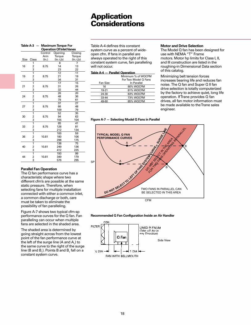
Parallel Fan OperationThe Q fan performance curve has acharacteristic shape where twodifferent cfm’s are possible at the samestatic pressure. Therefore, whenselecting fans for multiple installationconnected with either a common inlet,a common discharge or both, caremust be taken to eliminate thepossibility of fan paralleling.
Figure A-7 shows two typical cfm-spperformance curves for the Q fan. Fanparalleling can occur when multiplefans are selected in the shaded area.
The shaded area is determined bygoing straight across from the lowestpoint of the fan performance curve atthe left of the surge line (A and A1) tothe same curve to the right of the surgeline (B and B1). Points B and B1 fall on aconstant system curve.
Table A-3 — Maximum Torque For Operation Of Inlet VanesControl Opening Closing
Arm Torque TorqueSize Class (In.) (In.-Lb) (In.-Lb)
1 8 716 2 8.75 14 13
3 23 221 12 11
19 2 8.75 21 193 34 311 17 15
21 2 8.75 31 263 32 441 26 20
24 2 8.75 48 363 79 611 37 27
27 2 8.75 66 483 109 791 52 35
30 2 8.75 94 633 155 1041 65 41
33 2 8.75 128 813 212 1341 100 59
36 2 10.81 180 1063 298 1751 138 75
40 2 10.81 249 1363 412 2251 193 99
44 2 10.81 349 1793 576 295
Motor and Drive SelectionThe Model Q fan has been designed foruse with NEMA “T” Framemotors. Motor hp limits for Class I, II,and III construction are listed in theroughing-in Dimensional Data sectionof this catalog.
Minimizing belt tension forcesincreases bearing life and reduces fannoise. The Q fan and Super Q II fandrive selection is totally computerizedby the factory to achieve quiet, long lifeoperation. If Trane provides Q fandrives, all fan motor information mustbe made available to the Trane salesengineer.
Table A-4 defines this constantsystem curve as a percent of wide-open cfm. If fans in parallel arealways operated to the right of thisconstant system curve, fan parallelingwill not occur.
Table A-4 — Parallel OperationMinimum % of WOCFMFor Two Model Q Fans
Fan Size In Parallel16 80% WOCFM
19-21 81% WOCFM24-30 83% WOCFM33-44 73% WOCFM49-60 85% WOCFM
Figure A-7 — Selecting Model Q Fans in Parallel
Recommended Q Fan Configuration Inside an Air Handler
Side View

19
Recommended Super Q II Quiet (NC35)Floor-Mounted (Stacked) Configuration
ApplicationConsiderations
Operating Cost/EfficiencyThe quiet Q fan is a very efficient fan.The Q fan mixed-flow type airfoil thrustblades offer outstanding efficiency andoperating cost savings over such fantypes as plug fans. Designers cancompare the Q fan efficiency with otherfans by using the fan selection programand the Trane Customer Direct Service(C.D.S.™) Network FanMod program.
The Trane fan selection programprovides accurate part load energyconsumption no matter what fanmodulation method is selected. TheFanMod program compares two ormore fans economically for one ormore years. FanMod is an easy-to-useprogram for equipment life cycle costanalysis.
When comparing the Q fanperformance with centrifugal fans,remember to recalculate the fanexternal static pressure. The in-linedelivery of the Q fan often eliminatesthe need for a 90 degree turn right offthe fan outlet. Turns directlydownstream of the fan outlet consumeenergy and generate noise and,therefore, should be avoided wheneverpossible.
Recommended Super Q II (NC40)Plenum Configuration
Recommended Super Q II Multiple Fan (NC40)Low Height Plenum Configuration

20
ApplicationConsiderations
Q Fan Sound DataTrane Q fans are designed to be used inany installation where a standard airfoilcentrifugal fan can be used. The soundlevel of the Q fan in the difficult toattenuate lower frequencies is lowerthan that produced by standard airfoilcentrifugal fans with the same capacity.Sound levels in the higher octavebands compare favorably. Therefore,the Q fan will provide quieter soundlevels in a typical installation.
Designing the system for lower staticpressures and selecting the fan at highefficiency will result in quieter fanoperation, as well as power savings.
The best method of acoustical designmakes use of unit sound power levelsin all eight octave bands. These soundpower levels for each Trane Q fan canbe obtained from the Tranecomputerized fan selection program.
In the past, it has been an industrypractice to test air moving deviceswithin a reverberating room todetermine total sound power. This haspresented the problem ofdistinguishing between inlet anddischarge sound power ratings, wheresignificant differences do exist.
Trane engineers solved this problem bylocating the fan adjacent to thereverberating room and ducting to it.By turning the fan around, inlet anddischarge sound power can bemeasured separately and accurately.
By ducting both the inlet and outlet,radiated shell sound power wasdetermined. Using this method withthe Trane reverberant room thatconforms to ASHRAE standards,acoustical data on the Q fan issubstantially more accurate than fanratings made using conventionaltechniques. Tests covered all sizes andspeeds over the entire performancerange of the line. A computer programwas then used to determine the preciserelationship of speed, size, point ofoperation and frequency.
Plus silencer attenuation is shown inTables S-1 and S-2. Use the Trane fanselection program to obtain precisePlus attenuation with regeneratednoise included.
Trane ASA10B Sound AnalyzerTrane offers a low cost 10 octaveband sound analyzer for soundmeasurements. Capable of measuringnoise from 30 to 123 db soundpressure with flat, dbA and dbC soundLCb weightings this rugged meterpermits comparative and absolutesound measurements to be taken.
Ideas On How To Use The ASA10BThe ASA10B can be used on existingjobs to measure equipment soundlevels by octave bands. Compare thisdata with NC charts to determine whatfrequencies need to be attenuated andby how much. The type and cost ofnoise control options is a function ofthe problem frequency and amplitude.
On acoustical retrofits, the ASA10B canaccurately compare before and afternoise levels. Real measurementsestablish the benefit of the retrofit.
Trane Acoustics ProgramTrane has a system level acousticscomputer program that accuratelyconverts fan sound power to room NClevels. This program uses ASHRAEapproved algorithms and is the mostcomplete and accurate sound predictiveprogram in the HVAC industry. Use ofthe Trane acoustics program allows allsound paths to be checked andattenuated to achieve the desired roomsound levels without costlyoverdesigning. Contact your Trane salesengineer for more details on thisCustomer Direct Service (C.D.S.)Network program.
Q Fan/Super Q II Plus SilencersTrane has a unique silencer for theQ fan. This low turbulence, highattenuation silencer dramaticallyreduces airborne noise from the Q-Fan.A bulleted cylindrical silencer attenuatesmedium and high frequency noisegenerated by the Q Fan to a point wherethe Q Fan can be successfully installedin such sound sensitive applications asceiling plenums successfully.
Trane’s Plus silencer has a fieldrepositionable bullet (center body) thatcan be relocated close to the Q Fanoutlet. This unique feature eliminateslow frequency turbulence and makesthe Q fan quieter than plug fans or otheraxial or mixed flow fans. Pressure dropthrough the Plus silencer isapproximately .1-inch sp. The Plussilencer has been used on manyprojects in the last five years toconsistently create NC 15-35 spaces.
Table A-5 — Inlet Vane Sound DataDB Addition For Vane Position Indicated
Octave Mid- Wide 75% 50% 25%Band Frequency Open W/Open W/Open W/Open
1 63 +4 +8 +12 +142 125 +8 +9 +9 +103 200 +7 +8 +9 +94 500 +4 +5 +6 +65 1,000 0 0 0 06 2,000 0 0 0 07 4,000 0 0 0 08 8,000 0 0 0 0

21
SelectionProcedure
Q-Fan Sound Power By Octave Band At Nominal Cfm/SPFan Size 63 Hz 125 HZ 250 Hz 500 Hz 1000 Hz 2000 Hz 4000 Hz 8000 Hz
16 2 3 10 16 19 20 13 1219 2 3 10 16 19 19 13 1221 2 4 10 16 19 19 13 1124 3 4 10 16 19 19 13 1027 3 5 10 16 19 19 13 930 4 5 10 16 19 17 13 936 4 6 10 16 19 15 13 940 5 6 11 16 19 14 12 944 5 6 11 16 19 14 11 9
Table S-2 — Long Plus Silencer Attenuation (2D Length)*
Q-Fan Sound Power By Octave Band At Nominal Cfm/SPFan Size 63 Hz 125 HZ 250 Hz 500 Hz 1000 Hz 2000 Hz 4000 Hz 8000 Hz
16 3 6 19 32 37 39 26 2419 3 6 19 32 37 37 26 2421 4 7 19 32 37 37 26 2224 5 8 19 32 37 37 26 2027 6 9 19 32 37 37 26 1830 7 9 20 32 37 34 26 1836 8 11 20 32 37 30 25 1840 9 11 21 32 37 28 23 1844 9 12 21 32 37 28 22 18
*Approximate attenuations. Use the Trane Fan Selection Program for attenuation predictions that include silencer regenerated self-noise.
NOTE: Super Q II not available with Class III fans.
9If inlet vane modulation was selected,increase the rpm by 1 percent andincrease the bhp by 3 percent.10If the air density ratio is nonstandard(different than 1.00), the rpm is correctand the bhp must be multiplied by theair density ratio.11If the start-up air temperature is lowerthan the normal operatingtemperature, adjust the fan curve bhpfor the starting temperature. The nextlarger nominal hp motor is the correctmotor size.12If exceptional quiet is desired, choose ashort or long Q fan plus duct silencer.The plus silencer is a low turbulence,low pressure drop, high attenuationduct silencer. Subtract the attenuationsgiven in Tables S-1 and S-2 from theQ fan/Super Q II fan sound powerprojections. If silencer regeneratednoise is a concern, contact your localTrane sales engineer for furtherinformation.
Table S-1 — Short Plus Silencer Attenuation (1D Length)*
7Input the selection parameters into theTrane fan selection program and selectthe desired Q fan or proceed with amanual selection.8Manual Selection:aDetermine the air density ratio if non-standard air is being handled by theQ fan.bAdjust the external sp by the air densityratio.cUse the inlet and outlet area of the fanto calculate the inlet and outletvelocities. Use these velocities and theinlet and outlet Kt to correct theexternal static pressure to the rightvalue. Reselect the fan at the rightvalue.dFrom the performance table, select thedesired fan.
1Select the type of fan desired. TheSuper Q II should be used where fanradiation noise needs to be attenuated.2Position the Q fan to deliver air to thesystem and minimize adverse Kt effects.Straight-thru flow arrangements arebest.3Select the desired Q fan or Super Q IIfan options.4Compute the fan external static pressureand cfm requirements.5Determine which Kt effects apply to theQ fan installation.6If the Q fan is serving a VAV system,select AC frequency drive or inlet vanemodulations. (AC frequency drivemodulation is considerably quieter andmore efficient than Q fan inlet vanes.)Super Q II fans use AC frequency drivemodulation only.

22
PerformanceData
Fan Size 16”
Wheel Dia. 16.5 inches 419 mmInlet Area 2.05 square feet 0.190 m2
Outlet Area 1.70 square feet 0.158 m2
Tip Speed 4.32 x RPM 1.317ft./minute m/minute
Q Fan andSuper Q IISize 16
Minimum Fan RPM (Without VFRB Option)Motor Minimum Fan RPM
1800 RPM 4861200 RPM 324
Pressure Class LimitsClass Maximum RPM
I 2585II 3460III 4660
Table P-1 — Size 16 Q-FanCFM Out- Total Static PressureStd. let 1/4” 3/8” 1/2” 5/8” 3/4” 1” 1 1/4” 1 1/2” 1 3/4” 2”Air Vel. RPM BHP RPM BHP RPM BHP RPM BHP RPM BHP RPM BHP RPM BHP RPM BHP RPM BHP RPM BHP1000 588 934 0.08 1002 0.11 1068 0.13 1137 0.16 1204 0.19 1344 0.271200 705 1071 0.12 1127 0.14 1184 0.17 1239 0.20 1295 0.24 1408 0.31 1523 0.39 1642 0.481400 823 1214 0.16 1263 0.20 1311 0.231 1360 0.26 1408 0.29 1502 0.37 1601 0.45 1697 0.54 1796 0.64 1898 0.751600 941 1360 0.22 1404 0.26 1447 0.30 1489 0.33 1531 0.37 1617 0.45 1698 0.53 1785 0.62 1870 0.72 1953 0.821800 1058 1509 0.30 1548 0.34 1587 0.38 1626 0.42 1662 0.46 1739 0.54 1814 0.63 1886 0.73 1961 0.831 2039 0.932000 1176 1660 0.39 1695 0.43 1731 0.48 1766 0.52 1800 0.57 1867 0.65 1936 0.74 2004 0.84 2068 0.95 2135 1.062200 1294 1812 0.50 1844 0.54 1877 0.59 1909 0.64 1941 0.69 2002 0.78 2064 0.88 2127 0.99 2188 1.10 2249 1.212400 1411 1965 0.62 1995 0.68 2025 0.73 2054 0.78 2084 0.84 2142 0.94 2197 1.04 2254 1.15 2311 1.27 2369 1.382600 1529 2120 0.77 2147 0.83 2175 0.89 2202 0.94 2229 1.00 2283 1.12 2337 1.23 2387 1.34 2440 1.46 2493 1.582800 1647 2274 0.95 2300 1.01 2326 1.07 2351 1.13 2376 1.19 2427 1.32 2477 1.44 2526 1.57 2573 1.68 2622 1.813000 1764 2430 1.15 2454 1.21 2478 1.28 2501 1.34 2525 1.41 2573 1.54 2620 1.67 2666 1.81 2712 1.94 2755 2.063200 1882 2586 1.38 2608 1.44 2630 1.51 2653 1.58 2675 1.65 2720 1.79 2764 1.93 2808 2.08 2851 2.22 2894 2.363400 2000 2742 1.63 2763 1.70 2784 1.77 2805 1.85 2826 1.92 2868 2.07 2910 2.22 2951 2.37 2993 2.53 3033 2.683600 2117 2898 1.92 2918 1.99 2938 2.07 2958 2.15 2978 2.22 3018 2.38 3057 2.54 3096 2.70 3136 2.86 3174 3.023800 2235 3055 2.24 3074 2.32 3093 2.40 3112 2.48 3130 2.56 3168 2.72 3206 2.89 3243 3.06 3280 3.23 3317 3.404000 2352 3212 259 3230 2.68 3248 2.76 3266 2.84 3284 2.93 3319 3.10 3355 3.28 3391 3.45 3426 3.63 3461 3.814200 2470 3369 298 3386 3.07 3403 3.16 3420 3.25 3437 3.34 3471 3.52 3505 3.70 3539 3.88 3573 4.07 3607 4.254400 2588 3526 3.41 3543 3.50 3559 3.59 3575 3.69 3591 3.78 3624 3.97 3656 4.16 3689 4.35 3721 4.54 3754 4.744600 2705 3684 3.88 3699 3.98 3715 4.07 3730 4.17 3746 4.26 3777 4.46 3808 4.66 3839 4.86 3870 5.06 3901 5.264800 2823 3841 4.39 3856 4.49 3871 4.59 3886 4.69 3901 4.79 3931 5.00 3961 5.20 3990 5.41 4020 5.62 4050 5.835000 2941 3999 4.95 4013 5.05 4027 5.15 4042 5.26 4056 5.36 4085 5.57 4113 5.79 4142 6.00 4171 6.22 4199 6.445200 3058 4157 5.55 4170 5.65 4184 5.76 4198 5.87 4212 5.98 4239 6.20 4267 6.42 4294 6.64 4322 6.87 4349 7.095400 3176 4314 6.20 4328 6.31 4341 6.42 4354 6.53 4367 6.64 4394 6.87 4420 7.10 4447 7.33 4473 7.56 4500 7.805600 3294 4472 6.89 4485 7.01 4498 7.12 4511 7.24 4523 7.36 4549 7.59 4574 7.83 4600 8.06 4626 8.31 4651 8.55
CFM Out- Total Static PressureStd. let 2 1/4” 2 1/2” 3” 3 1/2” 4” 4 1/2” 5” 5 1/2” 6” 6 1/2”Air Vel. RPM BHP RPM BHP RPM BHP RPM BHP RPM BHP RPM BHP RPM BHP RPM BHP RPM BHP RPM BHP1600 941 2040 0.94 2129 1.061800 1058 2112 1.04 2188 1.16 2343 1.42 2482 1.662000 1176 2205 1.18 2274 1.30 2407 1.54 2546 1.82 2688 2.122200 1294 2307 1.33 2369 1.45 2495 1.71 2616 1.98 2741 2.28 2869 2.60 2999 2.942400 1411 2425 1.50 2478 1.63 2590 1.90 2705 2.18 2816 2.47 2930 2.78 3046 3.12 3164 3.48 3284 3.852600 1529 2546 1.71 2598 1.84 2698 2.11 2801 2.40 2908 2.71 3013 3.02 3114 3.34 3220 3.69 3328 4.07 3438 4.462800 1647 2671 1.94 2720 2.07 2817 2.35 2909 2.65 3005 2.97 3104 3.29 3203 3.62 3296 3.96 3393 4.32 3492 4.713000 1764 2801 2.20 2846 2.34 2938 2.62 3028 2.93 3114 3.25 3203 3.58 3296 3.92 3387 4.28 3479 4.65 3565 5.013200 1882 2935 2.49 2977 2.63 3063 2.93 3149 3.24 3233 3.57 3313 3.91 3396 4.26 3481 4.63 3569 5.00 3655 5.393400 2000 3074 2.83 3112 2.96 3192 3.27 3272 3.59 3353 3.92 3433 4.27 3507 4.63 3586 5.00 3665 5.39 3748 5.773600 2117 3213 3.18 3251 3.34 3324 3.64 3400 3.97 3477 4.31 3553 4.66 3628 5.03 3698 5.41 3772 5.81 3847 6.213800 2235 3354 3.57 3390 3.74 3460 4.05 3532 4.39 3604 4.74 3677 5.10 3748 5.47 3819 5.86 3889 6.26 3955 6.674000 2352 3497 3.99 3531 4.17 3601 4.52 3666 4.85 3734 5.21 3803 5.58 3872 5.96 3940 6.35 4008 6.76 4074 7.184200 247C 3641 4.44 3674 4.63 3740 5.01 3806 5.38 3868 5.72 3933 6.10 3998 6.50 4064 6.89 4129 7.30 4193 7.724400 2588 3786 4.94 3818 5.13 3881 5.53 3944 5.92 4004 6.27 4066 6.67 4128 7.07 4190 7.48 4253 7.89 4315 8.324600 2705 3932 5.47 3963 5.67 4024 6.09 4085 6.50 4144 6.91 4201 7.27 4260 7.68 4319 8.11 4379 8.54 4438 8.984800 2823 4079 6.04 4109 6.25 4168 6.68 4226 7.12 4284 7.55 4341 7.97 4395 8.35 4452 8.78 4508 9.22 4565 9.675000 2941 4228 6.66 4256 6.88 4313 7.33 4369 7.78 4425 8.22 4480 8.67 4535 9.11 4586 9.50 4641 9.955200 3058 4377 7.32 4404 7.55 4459 8.01 4513 8.48 4567 8.95 4620 9.415400 3176 4526 8.03 4553 8.27 4605 8.75 4658 9.23
CFM Out- Total Static PressureStd. let 7” 7 1/2” 8” 8 1/2” 9” 9 1/2” 10” 10 1/2” 11” 11 1/2”Air Vel. RPM BHP RPM BHP RPM BHP RPM BHP RPM BHP RPM BHP RPM BHP RPM BHP RPM BHP RPM BHP2600 1529 3548 4.862700 1588 3568 4.98 3674 5.402800 1647 3593 5.11 3694 5.53 3797 5.972900 1705 3622 5.25 3719 5.67 3817 6.11 3916 6.55 3980 6.853000 1764 3656 5.41 3749 5.82 3843 6.26 3937 6.71 4033 7.17 4091 7.453100 1823 3694 5.58 3783 5.99 3872 6.42 3963 6.87 4055 7.33 4147 7.80 4239 8.293200 1882 3740 5.78 3821 6.17 3906 6.59 3993 7.04 4081 7.50 4169 7.97 4259 8.46 4348 8.96 4400 9.243300 1941 3783 5.98 3866 6.39 3944 6.79 4027 7.23 4111 7.68 4196 8.16 4282 8.64 4368 9.14 4455 9.65 4501 9.923400 2000 3829 6.18 3909 6.60 3989 7.02 4065 7.43 4145 7.88 4227 8.35 4309 8.84 4392 9.33 4476 9.85 4560 10.373500 2058 3876 6.39 3954 6.81 4032 7.24 4106 7.65 4183 8.10 4261 8.56 4340 9.04 4420 9.54 4501 10.05 4582 10.573600 2117 3923 6.62 4001 7.04 4077 7.47 4153 7.91 4224 8.33 4299 8.79 4375 9.27 4452 9.76 4530 10.27 4608 10.793700 2176 3973 6.85 4049 7.27 4124 7.71 4198 8.15 4272 8.61 4340 9.04 4414 9.51 4487 10.00 4562 10.50 4637 11.023800 2235 4026 7.10 4097 7.53 4171 7.96 4244 8.41 4316 8.86 4388 9.33 4459 9.81 4526 10.26 4598 10.763900 2294 4081 7.35 4149 7.78 4219 8.23 4292 8.67 4362 9.13 4433 9.60 4503 10.08 4572 10.57 4637 11.034000 2352 4137 7.61 4203 8.05 4271 8.50 4339 8.95 4410 9.41 4478 9.88 4547 10.37 4615 10.864100 2411 4198 7.88 4259 8.32 4324 8.78 4390 9.24 4457 9.71 4526 10.17 4593 10.66 4660 11.16Performance based on 0.075 lbs. per cubic foot density (air at 70 F and 29.92 Hg Bar). Performance shown is for installation Type B: free inlet, ducted outlet.Power rating (BHP) does not include drive losses. Performance ratings do not include the effects of appurtenances in the airstream.When inlet vanes are used increase rpm 1 percent and brake horsepower 3 percent.Fan tables cover part of fan operating range; fan curves show full operating range.

23
PerformanceData
Q Fan andSuper Q IISize 16
Standard fans can be selected ONLY in the shaded area.Thrust restrains are to be used with fans Class 3 or motors 40 hp and up.
Minimum and Maximum Motor HP Ranges
Q Fan Size 16” Super Q Fan Size 16”
Min - Max Min - Max Min - Max Min - Max Min - MaxMotor HP Motor HP Motor HP Motor HP Motor HP
Class 1 Class 2 Class 3 Class 1 Class 2Arrangement 9 1 - 2 1.5 - 5 5 - 15 1 - 2 1.5 - 5Arrangement 1 — — 5 - 15 NA NA
____ Fan RPM Line- - - Motor HP Line

24
PerformanceData
Q Fan andSuper Q IISize 19
Fan Size 19”
Wheel Dia. 19.0 inches 483 mmInlet Area 2.61 square feet 0.242 m2
Outlet Area 2.30 square feet 0.214 m2
Tip Speed 4.97 x RPM 1.515ft./minute m/minute
Minimum Fan RPM (Without VFRB Option)Motor Minimum Fan RPM
1800 RPM 4171200 RPM 278
Pressure Class LimitsClass Maximum RPM
I 2345II 3145III 4040
Table P-2 — Size 19 Q FanCFM Out- Total Static PressureStd. let 1/4” 3/8” 1/2” 5/8” 3/4” 1” 1 1/4” 1 1/2” 1 3/4” 2”Air Vel. RPM BHP RPM BHP RPM BHP RPM BHP RPM BHP RPM BHP RPM BHP RPM BHP RPM BHP RPM BHP2000 869 907 0.15 962 0.19 1019 0.24 1074 0.29 1124 0.34 1235 0.45 1351 0.572200 956 977 0.18 1026 0.23 1078 0.28 1129 0.33 1179 0.38 1272 0.49 1375 0.62 1481 0.752400 1043 1049 0.22 1093 0.27 1140 0.32 1187 0.37 1234 0.43 1325 0.55 1409 0.67 1505 0.81 1602 0.952600 1130 1123 0.26 1163 0.31 1205 0.36 1248 0.42 1292 0.48 1378 0.60 1456 0.73 1538 0.87 1627 1.02 1717 1182800 1217 1198 0.31 1234 0.36 1272 0.42 1312 0.48 1352 0.54 1433 0.67 1512 0.80 1583 0.94 1660 1.09 1742 1263000 1304 1273 0.36 1307 0.42 1342 0.48 1378 0.54 1415 0.60 1491 0.74 1566 0.88 1638 1.03 1704 1.17 1775 1333200 1391 1350 0.42 1381 0.48 1413 0.54 1446 0.61 1481 0.67 1551 0.82 1622 0.97 1692 1.12 1759 1.27 1820 1423400 1478 1427 0.49 1456 0.55 1486 0.62 1517 0.69 1548 0.75 1614 0.90 1681 1.06 1747 1.22 1812 1.38 1875 1.553600 1565 1504 0.57 1531 0.64 1559 0.70 1588 0.77 1617 0.84 1679 0.99 1741 1.15 1804 1.32 1867 1.49 1928 1663800 1652 1582 0.66 1608 0.72 1634 0.79 1661 0.86 1688 0.94 1745 1.09 1804 1.26 1864 1.43 1923 1.61 1982 1.794000 1739 1660 0.75 1684 0.82 1709 0.89 1734 0.97 1760 1.04 1813 1.20 1868 1.37 1925 1.55 1982 1.74 2038 1934200 1826 1738 0.86 1761 0.93 1785 1.00 1809 1.08 1833 1.16 1883 1.32 1934 1.50 1988 1.68 2042 1.87 2096 2.074400 1913 1817 0.97 1839 1.04 1861 1.12 1884 1.20 1907 1.28 1954 1.45 2002 1.63 2053 1.82 2104 2.01 2156 2.214600 1999 1896 1.09 1916 1.17 1938 1.25 1959 1.33 1981 1.42 2026 1.59 2071 1.78 2119 1.97 2168 2.16 2216 2.374800 2086 1974 1.23 1994 1.31 2015 1.39 2035 1.48 2056 1.56 2098 1.74 2142 1.93 2186 2.13 2233 2.33 2279 2.545000 2173 2053 1.37 2073 1.46 2092 1.54 2111 1.63 2131 1.72 2172 1.91 2213 2.10 2256 2.30 2299 2.51 2344 2.725200 2260 2133 1.53 2151 1.62 2169 1.71 2188 1.80 2207 1.89 2246 2.08 2285 2.28 2326 2.48 2367 2.69 2410 2915400 2347 2212 1.70 2229 1.79 2247 1.88 2265 1.98 2283 2.07 2320 2.27 2358 2.47 2397 2.68 2436 2.90 2476 3125600 2434 2291 1.88 2308 1.98 2325 2.07 2343 2.17 2360 2.26 2396 2.47 2432 2.67 2469 2.89 2506 3.11 2544 3.345800 2521 2371 2.08 2387 2.17 2404 2.27 2420 2.37 2437 2.47 2471 2.68 2506 2.89 2541 3.11 2577 3.34 2614 3.576000 2608 2450 2.29 2466 2.39 2482 2.49 2498 2.59 2514 2.69 2547 2.90 2580 3.12 2614 3.35 2649 3.58 2684 3.826200 2695 2530 2.51 2545 2.61 2560 2.72 2576 2.82 2592 2.93 2623 3.14 2655 3.37 2688 3.60 2721 3.83 2755 4.086400 2782 2610 2.75 2624 2.85 2639 2.96 2654 3.07 2669 3.18 2700 3.40 2731 3.63 2762 3.86 2794 4.10 2826 4.356600 2869 2689 3.00 2704 3.11 2718 3.22 2732 3.33 2747 3.44 2777 3.67 2806 3.90 2837 4.14 2868 4.39 2899 4.64
CFM Out- Total Static PressureStd. let 2 1/4” 2 1/2” 3” 3 1/2” 4” 4 1/2” 5” 5 1/2” 6” 6 1/2”Air Vel. RPM BHP RPM BHP RPM BHP RPM BHP RPM BHP RPM BHP RPM BHP RPM BHP RPM BHP RPM BHP2800 1217 1826 1.42 1908 1603000 1304 1853 1.52 1930 1703200 1391 1887 1.60 1959 1.79 2105 2.173400 1478 1931 1.70 1994 1.89 2130 2.30 2267 2.703600 1565 1987 1.84 2040 2.01 2162 2.41 2290 2.85 2419 3.283800 1652 2040 1.97 2096 2.16 2201 2.53 2320 2.98 2442 3.44 2564 3.904000 1739 2094 2.11 2149 2.31 2249 2.68 2355 3.11 2470 3.59 2587 4.06 2702 4.564200 1826 2150 2.27 2203 2.46 2306 2.87 2399 3.27 2503 3.73 2614 4.25 2725 4.74 2835 5.264400 1913 2207 2.42 2259 2.63 2359 3.05 2449 3.46 2544 3.91 2647 4.42 2751 4.95 2858 5.46 2962 6.014600 1999 2266 2.58 2316 2.80 2413 3.23 2507 3.68 2592 4.11 2684 4.59 2783 5.14 2883 5.70 2985 6.23 3085 6.804800 2086 2327 2.76 2374 2.98 2469 3.44 2561 3.89 2649 4.36 2729 4.81 2819 5.32 2915 5.91 3011 6.49 3108 7.045000 2173 2389 2.94 2434 3.17 2525 3.64 2615 4.11 2702 4.60 2786 5.08 2863 5.56 2949 6.10 3042 6.72 3134 7.325200 2260 2453 3.14 2496 3.37 2584 3.85 2671 4.35 2756 4.84 2839 5.35 2912 5.82 2992 6.35 3076 6.92 3166 7.575400 2347 2518 3.35 2559 3.59 2644 4.08 2728 4.59 2811 5.11 2892 5.61 2971 6.14 3040 6.63 3118 7.19 3199 7.795600 2434 2584 3.57 2624 3.81 2704 4.31 2786 4.84 2867 5.37 2946 5.89 3024 6.44 3099 6.99 3166 7.49 3241 8.085800 2521 2651 3.81 2690 4.05 2767 4.56 2846 5.10 2924 5.64 3001 6.20 3078 6.74 3152 7.31 3224 7.87 3288 8.406000 2608 2720 4.06 2756 4.31 2831 4.83 2906 5.37 2982 5.93 3058 6.50 3132 7.06 3205 7.64 3277 8.22 3339 8.766200 2695 2789 4.33 2824 4.58 2896 5.11 2968 5.66 3042 6.23 3115 6.81 3188 7.40 3260 7.98 3330 8.58 3398 9.196400 2782 2859 4.61 2893 4.86 2962 5.40 3031 5.96 3102 6.54 3174 7.13 3245 7.74 3315 8.35 3384 8.95 3452 9.576600 2869 2930 4.90 2963 5.16 3028 5.71 3096 6.28 3164 6.86 3234 7.47 3303 8.09 3371 8.72 3439 9.35 3505 9.966800 2956 3002 5.21 3033 5.48 3096 6.03 3162 6.61 3227 7.21 3294 7.82 3362 8.45 3428 9.10 3494 9.75 3560 10.377000 3043 3075 5.54 3104 5.81 3165 6.38 3227 6.96 3292 7.56 3356 8.19 3422 8.83 3487 9.49 3551 10.15 3615 10.827200 3130 3147 5.88 3176 6.16 3235 6.73 3295 7.33 3357 7.94 3419 8.57 3482 9.22 3546 9.89 3609 10.57 3672 11.267400 3217 3221 6.24 3249 6.53 3305 7.11 3363 7.71 3423 8.33 3483 8.97 3544 9.63 3605 10.31 3668 11.00 3729 11.70
CFM Out- Total Static PressureStd. let 7” 7 1/2” 8” 8 1/2” 9” 9 1/2” 10” 10 1/2” 11” 11 1/2”Air Vel. RPM BHP RPM BHP RPM BHP RPM BHP RPM BHP RPM BHP RPM BHP RPM BHP RPM BHP RPM BHP4800 2086 3205 7.635000 2173 3227 7.93 3321 8.50 3412 9.155200 2260 3254 8.20 3343 8.83 3434 9.42 3522 10.085400 2347 3286 8.46 3371 9.12 3457 9.77 3544 10.38 3629 11.065600 2434 3319 8.70 3403 9.40 3485 10.08 3567 10.76 3652 11.38 3734 12.08 3816 12.805800 2521 3361 9.01 3436 9.65 3517 10.38 3596 11.08 3676 11.78 3758 12.43 3838 13.14 3916 13.886000 2608 3407 9.35 3478 9.98 3551 10.65 3629 11.41 3706 12.13 3782 12.85 3860 13.58 3939 14.246200 2695. 3458 9.73 3524 10.35 3593 11.00 3663 11.69 3739 12.47 3813 13.22 3887 13.97 3962 14.726400 2782 3518 10.20 3575 10.76 3639 11.40 3705 12.07 3773 12.78 3847 13.58 3918 14.356600 2869 3571 10.61 3635 11.26 3689 11.83 3752 12.49 3816 13.18 3882 13.91 3953 14.736800 2956 3625 11.03 3688 11.69 3750 12.36 3802 12.95 3863 13.63 3925 14.347000 3043 3679 11.47 3741 12.14 3803 12.83 3862 13.52 3913 14.11 3972 14.817200 3130 3734 11.95 3796 12.61 3856 13.31 3916 14.01 3974 14.727400 3217 3790 12.41 3850 13.12 3910 13.80 3969 14.527600 3304 3847 12.89 3906 13.62 3965 14.317800 3391 3905 13.38 3963 14.12 4020 14.87Performance based on 0.075 lbs. per cubic foot density (air at 70 F and 29.92 Hg Bar). Performance shown is for installation Type B: free inlet, ducted outlet.Power rating (BHP) does not include drive losses. Performance ratings do not include the effects of appurtenances in the airstream.When inlet vanes are used increase rpm 1 percent and brake horsepower 3 percent.Fan tables cover part of fan operating range; fan curves show full operating range.

25
PerformanceData
Q Fan andSuper Q IISize 19
Standard fans can be selected ONLY in the shaded area.Thrust restrains are to be used with fans Class 3 or motors 40 hp and up.
Minimum and Maximum Motor HP Ranges
Q Fan Size 19” Super Q Fan Size 19”
Min - Max Min - Max Min - Max Min - Max Min - MaxMotor HP Motor HP Motor HP Motor HP Motor HP
Class 1 Class 2 Class 3 Class 1 Class 2Arrangement 9 1 - 3 3 - 7.5 7.5 - 15 1 - 3 3 - 7.5Arrangement 1 — — 7.5 - 15 NA NA
____ Fan RPM Line- - - Motor HP Line

26
Fan Size 21”
Wheel Dia. 21.5 inches 546 mmInlet Area 3.31 square feet 0.308 m2
Outlet Area 2.88 square feet 0.268 m2
Tip Speed 5.63 x RPM 1.716ft./minute m/minute
Minimum Fan RPM (Without VFRB Option)Motor Minimum Fan RPM
1800 RPM 3801200 RPM 253
PerformanceData
Q Fan andSuper Q IISize 21
Pressure Class LimitsClass Maximum RPM
I 2070II 2780III 3740
Table P-3 — Size 21 Q-FanCFM Out- Total Static PressureStd. let 1/4” 3/8” 1/2” 5/8” 3/4” 1” 1 1/4” 1 1/2” 1 3/4” 2”Air Vel. RPM BHP RPM BHP RPM BHP RPM BHP RPM BHP RPM BHP RPM BHP RPM BHP RPM BHP RPM BHP2600 902 810 0.20 859 0.25 908 0.31 957 0.38 1001 0.44 1096 0.58 1197 0.742800 972 859 0.23 903 0.29 949 0.35 995 0.42 1039 0.48 1121 0.62 1214 0.79 1308 0.963000 1041 909 0.26 949 0.33 991 0.39 1034 0.46 1077 0.53 1155 0.67 1236 0.83 1323 1.02 1411 1.203200 1111 959 0.30 996 0.37 1035 0.44 1075 0.51 1116 0.58 1194 0.74 1265 0.89 1344 1.07 1426 1.27 1507 1.463400 1180 1011 0.35 1045 0.41 1081 0.48 1118 0.56 1156 0.64 1231 0.80 1302 0.96 1369 1.13 1445 1.34 1523 1.533600 1250 1062 0.40 1094 0.47 1128 0.54 1163 0.61 1198 0.70 1270 0.86 1339 1.04 1401 1.21 1469 1.40 1541 1.623800 1319 1115 0.45 1145 0.52 1176 0.60 1208 0.68 1242 0.76 1309 0.93 1376 1.11 1440 1.30 1499 1.48 1564 1.694000 1388 1167 0.51 1196 0.59 1225 0.66 1255 0.74 1286 0.83 1350 1.01 1415 1.20 1477 1.39 1537 1.58 1592 1.784200 1458 1220 0.58 1247 0.65 1274 0.73 1303 0.82 1332 0.90 1393 1.09 1454 1.28 1515 1.48 1573 1.68 1626 1.884400 1527 1273 0.65 1299 0.73 1325 0.81 1352 0.90 1379 0.99 1436 1.17 1495 1.37 1553 1.58 1610 1.79 1665 2.014600 1597 1327 0.73 1351 0.81 1376 0.89 1401 0.98 1427 1.07 1481 1.27 1536 1.47 1593 1.69 1648 1.91 1702 2.124800 1666 1380 0.81 1403 0.90 1427 0.98 1451 1.07 1476 1.17 1527 1.37 1580 1.58 1633 1.80 1687 2.02 1739 2.255000 1736 1434 0.90 1456 0.99 1479 1.08 1502 1.17 1525 1.27 1573 1.47 1624 1.69 1675 1.91 1727 2.15 1778 2.385200 1805 1488 1.00 1509 1.09 1531 1.18 1553 1.28 1575 1.38 1621 1.59 1669 1.80 1718 2.03 1767 2.27 1817 2.525400 1875 1542 1.11 1562 1.20 1583 1.30 1604 1.39 1625 1.50 1669 1.71 1715 1.93 1762 2.16 1809 2.41 1857 2.665600 1944 1596 1.22 1616 1.32 1636 1.41 1656 1.52 1676 1.62 1718 1.84 1761 2.06 1806 2.30 1852 2.55 1898 2.815800 2013 1651 1.34 1669 1.44 1688 1.54 1708 1.65 1727 1.75 1768 1.97 1809 2.21 1852 2.45 1895 2.70 1940 2966000 2083 1705 1.47 1723 1.57 1741 1.68 1760 1.78 1779 1.89 1817 2.12 1857 2.36 1898 2.60 1940 2.86 1982 3.136200 2152 1759 1.61 1777 1.71 1795 1.82 1813 1.93 1831 2.04 1868 2.27 1906 2.52 1945 2.77 1986 3.03 2026 3.306400 2222 1814 1.76 1831 1.86 1848 1.97 1865 2.09 1883 2.20 1919 2.44 1955 2.68 1993 2.94 2031 3.21 2071 3.486600 2291 1869 1.91 1885 2.02 1902 2.14 1918 2.25 1935 2.37 1970 2.61 2005 2.86 2041 3.12 2078 3.39 2116 3.676800 2361 1923 2.08 1939 2.19 1955 2.31 1971 2.43 1988 2.55 2021 2.79 2055 3.05 2090 3.32 2125 3.59 2162 3.877000 2430 1978 2.25 1993 2.37 2009 2.49 2025 2.61 2041 2.73 2073 2.99 2106 3.25 2139 3.52 2173 3.80 2208 4.097200 2500 2033 2.44 2048 2.56 2063 2.68 2078 2.80 2093 2.93 2125 3.19 2156 3.45 2189 3.73 2222 4.01 2256 4.31
CFM Out- Total Static PressureStd. let 2 1/4” 2 1/2” 3” 3 1/2” 4” 4 1/2” 5” 5 1/2” 6” 6 1/2”Air Vel. RPM BHP RPM BHP RPM BHP RPM BHP RPM BHP RPM BHP RPM BHP RPM BHP RPM BHP RPM BHP3600 1250 1615 1.83 1687 2.063800 1319 1633 1.92 1703 2.144000 1388 1656 2.01 1721 2.25 1852 2.734200 1458 1682 2.10 1743 2.35 1868 2.854400 1527 1715 2.21 1769 2.44 1887 2.97 2007 3.494600 1597 1754 2.35 1801 2.56 1910 3.08 2023 3.64 2137 4.194800 1666 1791 2.48 1840 2.72 1935 3.19 2043 3.77 2153 4.33 2261 4.945000 1736 1828 2.62 1877 2.86 1966 3.34 2067 3.91 2170 4.51 2276 5.095200 1805 1866 2.77 1914 3.01 2001 3.50 2092 4.04 2192 4.66 2292 5.29 2394 5.905400 1875 1904 2.92 1951 3.17 2042 3.69 2124 4.20 2215 4.80 2312 5.46 2410 6.09 2507 6.765600 1944 1944 3.07 1989 3.34 2078 3.87 2158 4.39 2243 4.97 2335 5.63 2428 6.31 2522 6.96 2615 7.665800 2013 1984 3.23 2029 3.51 2116 4.06 2199 4.62 2275 5.16 2359 5.79 2449 6.50 2539 7.20 2631 7.87 2720 8.616000 2083 2026 3.40 2069 3.68 2153 4.26 2236 4.83 2310 5.38 2388 5.99 2471 6.66 2559 7.41 2646 8.14 2735 8.836200 2152 2067 3.58 2109 3.87 2192 4.46 2273 5.04 2351 5.65 2421 6.22 2499 6.88 2582 7.62 2666 8.37 2751 9.126400 2222 2111 3.77 2151 4.06 2231 4.66 2311 5.26 2388 5.88 2461 6.51 2529 7.11 2606 7.81 2688 8.60 2769 9.376600 2291 2154 3.96 2193 4.26 2272 4.87 2349 5.50 2425 6.12 2498 6.77 2563 7.37 2635 8.05 2710 8.79 2791 9.626800 2361 2199 4.17 2236 4.47 2312 5.09 2388 5.74 2462 6.37 2535 7.03 2604 7.70 2667 8.33 2738 9.05 2815 9.877000 2430 2244 4.38 2281 4.69 2354 5.32 2428 5.98 2500 6.65 2572 7.31 2641 7.99 2702 8.62 2769 9.33 2839 10.097200 2500 2290 4.61 2325 4.92 2396 5.56 2468 6.23 2539 6.91 2609 7.59 2678 8.29 2744 8.99 2803 9.64 2869 10.397400 2569 2336 4.85 2371 5.16 2439 5.81 2509 6.49 2579 7.19 2647 7.90 2715 8.59 2780 9.31 2844 10.04 2901 10.717600 2638 2384 5.09 2416 5.41 2483 6.07 2550 6.76 2619 7.47 2686 8.20 2752 8.90 2817 9.64 2880 10.38 2936 11.067800 2708 2431 5.35 2463 5.67 2528 6.34 2593 7.04 2659 7.76 2725 8.50 2790 9.25 2855 9.98 2917 10.74 2978 11.508000 2777 2479 5.62 2510 5.95 2573 6.63 2636 7.33 2701 8.06 2765 8.82 2829 9.58 2892 10.32 2954 11.10 3014 11.888200 2847 2528 5.90 2558 6.24 2619 6.92 2680 7.64 2742 8.38 2806 9.14 2868 9.92 2930 10.71 2991 11.47 3051 12.26
CFM Out- Total Static PressureStd. let 7” 7 1/2” 8” 8 1/2” 9” 9 1/2” 10” 10 1/2” 11” 11 1/2”Air Vel. RPM BHP RPM BHP RPM BHP RPM BHP RPM BHP RPM BHP RPM BHP RPM BHP RPM BHP RPM BHP6000 2083 2821 9.606200 2152 2836 9.84 2919 10.646400 2222 2851 10.15 2934 10.89 3015 11.716600 2291 2870 10.42 2951 11.16 3030 11.98 3108 12.836800 2361 2891 10.68 2967 11.51 3046 12.27 3123 13.11 3199 13.997000 2430 2914 10.95 2988 11.79 3063 12.64 3139 13.43 3214 14.297200 2500 2937 11.18 3011 12.08 3083 12.95 3155 13.82 3230 14.627400 2569 2966 11.49 3033 12.32 3105 13.25 3175 14.157600 2638 2997 11.83 3061 12.64 3127 13.50 3197 14.477800 2708 3031 12.19 3092 12.99 3154 13.84 3222 14.808000 2777 3073 12.66 3125 13.37 3184 14.218200 2847 3110 13.07 3160 13.78 3217 14.608400 2916 3146 13.48 3203 14.308600 2986 3183 13.90 3239 14.748800 3055 3220 14.329000 3125 3258 14.76Performance based on 0.075 lbs. per cubic foot density (air at 70 F and 29.92 Hg Bar). Performance shown is for installation Type B: free inlet, ducted outlet.Power rating (BHP) does not include drive losses. Performance ratings do not include the effects of appurtenances in the airstream.When inlet vanes are used increase rpm 1 percent and brake horsepower 3 percent.Fan tables cover part of fan operating range; fan curves show full operating range.

27
PerformanceData
Q Fan andSuper Q IISize 21
Standard fans can be selected ONLY in the shaded area.Thrust restrains are to be used with fans Class 3 or motors 40 hp and up.
Minimum and Maximum Motor HP Ranges
Q Fan Size 21” Super Q Fan Size 21”
Min - Max Min - Max Min - Max Min - Max Min - MaxMotor HP Motor HP Motor HP Motor HP Motor HP
Class 1 Class 2 Class 3 Class 1 Class 2Arrangement 9 1 - 5 3 - 10 10 - 15 1 - 5 3 - 10Arrangement 1 — — 10 - 15 NA NA
____ Fan RPM Line- - - Motor HP Line

28
Fan Size 24”
Wheel Dia. 24.5 inches 622 mmInlet Area 4.32 square feet 0.401 m2
Outlet Area 3.73 square feet 0.347 m2
Tip Speed 6.41 x RPM 1.954ft./minute m/minute
Minimum Fan RPM (Without VFRB Option)Motor Minimum Fan RPM
1800 RPM 5351200 RPM 356
PerformanceData
Q Fan andSuper Q IISize 24
Pressure Class LimitsClass Maximum RPM
I 1772II 2380III 3200
Table P-4 — Size 24 Q-FanCFM Out- Total Static PressureStd. let 1/4” 3/8” 1/2” 5/8” 3/4” 1” 1 1/4” 1 1/2” 1 3/4” 2”•Air Vel. RPM BHP RPM BHP RPM BHP RPM BHP RPM BHP RPM BHP RPM BHP RPM BHP RPM BHP RPM BHP3000 804 639 0.2 685 0.3 730 0.3 773 0.4 817 0.5 908 0.73400 911 703 0.3 741 0.3 782 0.4 822 0.5 861 0.6 937 0.7 1018 0.93800 1018 769 0.3 803 0.4 837 0.5 874 0.6 910 0.7 978 0.8 1048 1.0 1120 1.34200 1126 836 0.4 867 0.5 897 0.6 929 0.7 962 0.8 1027 1.0 1088 1.2 1151 1.4 1215 1.6 1282 1.94600 1233 905 0.5 933 0.6 961 0.7 989 0.8 1018 0.9 1078 1.1 1136 1.3 1192 1.5 1249 1.8 1308 2.05000 1340 974 0.6 1000 0.7 1026 0.8 1052 0.9 1077 1.0 1132 1.2 1186 1.4 1240 1.7 1291 1.9 1344 2.25400 1447 1044 0.7 1068 0.8 1092 0.9 1116 1.0 1139 1.2 1188 1.4 1239 1.6 1290 1.9 1340 2.1 1387 2.45800 1554 1114 0.9 1137 1.0 1159 1.1 1181 1.2 1204 1.3 1248 1.6 1295 1.8 1342 2.1 1389 2.3 1435 2.66200 1662 1185 1.0 1206 1.2 1227 1.3 1248 1.4 1269 1.5 1310 1.8 1352 2.0 1397 2.3 1441 2.5 1485 2.86600 1769 1256 1.2 1276 1.3 1296 1.5 1315 1.6 1335 1.7 1374 2.0 1413 2.2 1453 2.5 1495 2.8 1537 3.17000 1876 1328 1.4 1346 1.6 1365 1.7 1383 1.8 1402 1.9 1439 2.2 1475 2.5 1512 2.8 1551 3.1 1591 3.47400 1983 1399 1.7 1417 1.8 1434 1.9 1452 2.1 1470 2.2 1505 2.5 1540 2.8 1574 3.1 1609 3.4 1646 3.77800 2091 1471 1.9 1488 2.1 1505 2.2 1521 2.3 1538 2.5 1571 2.8 1605 3.1 1638 3.4 1670 3.7 1704 4.08200 2198 1544 2.2 1559 2.3 1575 2.5 1591 2.6 1607 2.8 1639 3.1 1670 3.4 1702 3.7 1732 4.1 1764 4.48600 2305 1616 2.5 1631 2.7 1646 2.8 1661 3.0 1676 3.1 1706 3.4 1737 3.8 1767 4.1 1797 4.5 1826 4.89000 2412 1688 2.8 1703 3.0 1717 3.2 1731 3.3 1746 3.5 1775 3.8 1804 4.2 1833 4.5 1861 4.9 1890 5.29400 2520 1761 3.2 1775 3.4 1788 3.5 1802 3.7 1816 3.9 1844 4.2 1871 4.6 1899 4.9 1927 5.3 1954 5.79800 2627 1833 3.6 1847 3.8 1860 4.0 1873 4.1 1886 4.3 1913 4.7 1939 5.0 1966 5.4 1992 5.8 2019 6.2
10200 2734 1906 4.0 1919 4.2 1932 4.4 1944 4.6 1957 4.8 1982 5.1 2008 5.5 2033 5.9 2059 6.3 2084 6.710600 2841 1979 4.5 1991 4.7 2003 4.9 2016 5.1 2028 5.2 2052 5.6 2077 6.0 2101 6.4 2126 6.8 2150 7.211000 2949 2052 5.0 2064 5.2 2075 5.4 2087 5.6 2099 5.8 2122 6.2 2146 6.6 2170 7.0 2193 7.4 2217 7.811400 3056 2125 5.6 2136 5.7 2147 5.9 2159 6.1 2170 6.3 2193 6.7 2216 7.2 2238 7.6 2261 8.0 2284 8.411800 3163 2198 6.1 2209 6.3 2220 6.5 2231 6.7 2242 6.9 2264 7.4 2286 7.8 2308 8.2 2330 8.7 2352 9.112200 3270 2271 6.7 2281 7.0 2292 7.2 2303 7.4 2313 7.6 2334 8.0 2356 8.4 2377 8.9 2398 9.3 2420 9.8
CFM Out- Total Static PressureStd. let 2 1/4” 2 1/2” 3” 3 1/2” 4” 4 1/2” 5” 5 1/2” 6” 6 1/2”Air Vel. RPM BHP RPM BHP RPM BHP RPM BHP RPM BHP RPM BHP RPM BHP RPM BHP RPM BHP RPM BHP5000 1340 1397 2.5 1451 2.85400 1447 1435 2.7 1484 3.0 1585 3.65800 1554 1479 2.9 1524 3.2 1615 3.8 1710 4.5 1806 5.26200 1662 1528 3.1 1571 3.4 1654 4.1 1739 4.8 1828 5.5 1918 6.36600 1769 1578 3.4 1619 3.7 1697 4.4 1776 5.1 1857 5.8 1940 6.6 2025 7.47000 1876 1630 3.7 1669 4.0 1745 4.7 1818 5.4 1894 6.1 1969 6.9 2048 7.7 2128 8.67400 1983 1684 4.0 1721 4.3 1794 5.0 1866 5.8 1935 6.5 2006 7.3 2078 8.1 2152 9.0 2227 9.9 2303 10.87800 2091 1740 4.4 1775 4.7 1845 5.4 1914 6.2 1980 6.9 2047 7.7 2114 8.5 2182 9.4 2252 10.3 2324 11.28200 2198 1797 4.7 1831 5.1 1898 5.8 1964 6.6 2029 7.4 2091 8.1 2155 9.0 2220 9.9 2284 10.8 2350 11.78600 2305 1856 5.1 1887 5.5 1952 6.2 2016 7.0 2079 7.8 2141 8.7 2200 9.5 2260 10.4 2322 11.3 2383 12.29000 2412 1918 5.6 1947 5.9 2008 6.7 2069 7.5 2130 8.3 2190 9.2 2249 10.1 2305 10.9 2363 11.8 2421 12.89400 2520 1980 6.0 2008 6.4 2064 7.2 2124 8.0 2182 8.8 2240 9.7 2297 10.6 2354 11.6 2407 12.4 2463 13.49800 2627 2045 6.6 2070 6.9 2124 7.7 2179 8.6 2236 9.4 2292 10.3 2347 11.2 2402 12.2 2456 13.1 2507 14.1
10200 2734 2110 7.1 2135 7.5 2185 8.3 2237 9.2 2292 10.0 2345 10.9 2399 11.9 2452 12.8 2505 13.8 2557 14.810600 2841 2175 7.6 2199 8.1 2247 8.9 2296 9.8 2347 10.7 2400 11.6 2452 12.5 2503 13.5 2554 14.5 2605 15.511000 2949 2241 8.2 2264 8.7 2311 9.6 2357 10.4 2405 11.3 2456 12.3 2506 13.2 2556 14.2 2606 15.2 2655 16.311400 3056 2307 8.9 2330 9.3 2375 10.2 2419 11.1 2465 12.1 2512 13.0 2562 14.0 2610 15.0 2658 16.0 2705 17.111800 3163 2374 9.6 2396 10.0 2440 10.9 2483 11.9 2526 12.8 2571 13.8 2617 14.8 2665 15.8 2711 16.8 2758 17.912200 3270 2441 10.3 2462 10.7 2505 11.7 2547 12.7 2588 13.6 2631 14.6 2675 15.6 2721 16.6 2766 17.7 2811 18.812600 3378 2509 11.0 2529 11.5 2571 12.5 2612 13.5 2651 14.5 2692 15.5 2734 16.5 2777 17.6 2822 18.6 2865 19.713000 3485 2577 11.8 2597 12.3 2637 13.3 2677 14.3 2716 15.4 2754 16.4 2795 17.5 2835 18.5 2877 19.6 2921 20.713400 3592 2645 12.7 2664 13.2 2703 14.2 2742 15.2 2781 16.3 2819 17.4 2856 18.4 2895 19.5 2935 20.7 2976 21.813800 3699 2714 13.5 2733 14.1 2770 15.1 2808 16.2 2845 17.3 2883 18.4 2919 19.5 2956 20.6 2995 21.7 3033 22.914200 3806 2783 14.5 2801 15.0 2838 16.1 2874 17.2 2911 18.3 2947 19.4 2984 20.6 3018 21.7 3055 22.8 3092 24.0
CFM Out- Total Static PressureStd. let 7” 7 1/2” 8” 8 1/2” 9” 9 1/2” 10” 10 1/2” 11” 11 1/2”Air Vel. RPM BHP RPM BHP RPM BHP RPM BHP RPM BHP RPM BHP RPM BHP RPM BHP RPM BHP RPM BHP8600 2305 2446 13.2 2510 14.3 2575 15.3 2640 16.49000 2412 2480 13.8 2539 14.8 2600 15.9 2662 16.9 2724 18.0 2787 19.29400 2520 2519 14.4 2574 15.4 2631 16.5 2689 17.6 2748 18.7 2808 19.8 2867 21.0 2927 22.29800 2627 2561 15.1 2614 16.1 2667 17.2 2722 18.3 2777 19.4 2833 20.5 2890 21.6 2947 22.9 3004 24.1
10200 2734 2605 15.8 2657 16.8 2708 17.9 2760 19.0 2811 20.1 2864 21.3 2917 22.5 2971 23.7 3026 24.8 3081 26.110600 2841 2655 16.6 2702 17.6 2751 18.6 2800 19.7 2850 20.9 2899 22.0 2950 23.2 3001 24.5 3052 25.7 3104 27.011000 2949 2703 17.4 2752 18.5 2796 19.5 2844 20.6 2891 21.7 2939 22.9 2986 24.1 3035 25.3 3084 26.6 3133 27.811400 3056 2753 18.2 2800 19.3 2846 20.4 2890 21.5 2935 22.6 2981 23.8 3027 25.0 3074 26.2 3119 27.4 3166 28.711800 3163 2804 19.0 2849 20.2 2895 21.3 2940 22.5 2984 23.6 3026 24.7 3070 25.9 3114 27.2 3159 28.412200 3270 2856 19.9 2900 21.1 2945 22.2 2989 23.4 3032 24.6 3075 25.8 3115 26.9 3158 28.212600 3378 2909 20.9 2952 22.0 2995 23.2 3038 24.4 3081 25.7 3123 26.9 3165 28.113000 3485 2963 21.9 3005 23.0 3047 24.2 3089 25.5 3131 26.7 3172 28.013400 3592 3018 22.9 3059 24.1 3100 25.3 3141 26.5 3182 27.813800 3699 3073 24.1 3115 25.2 3154 26.4 3194 27.714200 3806 3130 25.2 3171 26.414600 3914 3189 26.4Performance based on 0.075 lbs. per cubic foot density (air at 70 F and 29.92 Hg Bar). Performance shown is for installation Type B: free inlet, ducted outlet.Power rating (BHP) does not include drive losses. Performance ratings do not include the effects of appurtenances in the airstream.When inlet vanes are used increase rpm 1 percent and brake horsepower 3 percent.Fan tables cover part of fan operating range; fan curves show full operating range.

29
PerformanceData
Q Fan andSuper Q IISize 24
Standard fans can be selected ONLY in the shaded area.Thrust restrains are to be used with fans Class 3 or motors 40 hp and up.
Minimum and Maximum Motor HP Ranges
Q Fan Size 24” Super Q Fan Size 24”
Min - Max Min - Max Min - Max Min - Max Min - MaxMotor HP Motor HP Motor HP Motor HP Motor HP
Class 1 Class 2 Class 3 Class 1 Class 2Arrangement 9 1 - 5 5 - 15 15-30 1 - 5 5 - 10Arrangement 1 — — 15 - 30 NA NA
____ Fan RPM Line- - - Motor HP Line

30
Fan Size 27”
Wheel Dia. 27.0 inches 686 mmInlet Area 5.20 square feet 0.483 m2
Outlet Area 4.54 square feet 0.422 m2
Tip Speed 7.07 x RPM 2.155ft./minute m/minute
Minimum Fan RPM (Without VFRB Option)Motor Minimum Fan RPM
1800 RPM 4371200 RPM 291
PerformanceData
Q Fan andSuper Q IISize 27
Pressure Class LimitsClass Maximum RPM
I 1610II 2160III 2908
Table P-5 — Size 27 Q-FanCFM Out- Total Static PressureStd. let 1/4” 3/8” 1/2” 5/8” 3/4” 1” 1 1/4” 1 1/2” 1 3/4” 2”Air Vel. RPM BHP RPM BHP RPM BHP RPM BHP RPM BHP RPM BHP RPM BHP RPM BHP RPM BHP RPM BHP3000 660 510 0.2 559 0.3 607 0.3 657 0.43500 770 564 0.2 607 0.3 649 0.4 690 0.5 731 0.64000 881 623 0.3 658 0.4 697 0.5 734 0.6 769 0.7 842 0.9 918 1.14500 991 684 0.4 715 0.5 747 0.6 781 0.7 815 0.8 878 1.0 943 1.2 1011 1.55000 1101 746 0.5 775 0.6 803 0.7 832 0.8 863 0.9 923 1.1 979 1.4 1038 1.6 1098 1.9 1160 2.25500 1211 810 0.6 836 0.7 862 0.8 887 0.9 914 1.0 970 1.3 1023 1.5 1075 1.8 1127 2.1 1182 2.46000 1321 874 0.7 898 0.8 922 1.0 945 1.1 969 1.2 1020 1.4 1070 1.7 1119 2.0 1166 2.3 1214 2.66500 1431 939 0.9 961 1.0 983 1.1 1005 1.2 1027 1.4 1072 1.6 1119 1.9 1165 2.2 1210 2.5 1253 2.97000 1541 1005 1.1 1026 1.2 1046 1.3 1067 1.4 1087 1.6 1127 1.9 1170 2.2 1214 2.5 1256 2.8 1298 3.17500 1651 1071 1.3 1090 1.4 1109 1.5 1129 1.7 1148 1.8 1185 2.1 1224 2.4 1264 2.7 1305 3.1 1345 3.48000 1762 1138 1.5 1156 1.6 1174 1.8 1191 1.9 1209 2.1 1245 2.4 1280 2.7 1317 3.0 1355 3.4 1393 3.78500 1872 1205 1.7 1221 1.9 1238 2.0 1255 2.2 1272 2.4 1306 2.7 1338 3.0 1372 3.4 1407 3.7 1443 4.19000 1982 1272 2.0 1287 2.2 1303 2.4 1319 2.5 1335 2.7 1367 3.0 1399 3.4 1430 3.7 1462 4.1 1495 4.59500 2092 1339 2.4 1354 2.5 1369 2.7 1384 2.9 1399 3.0 1429 3.4 1459 3.8 1489 4.1 1518 4.5 1549 4.9
10000 2202 1406 2.7 1420 2.9 1435 3.1 1449 3.2 1463 3.4 1492 3.8 1521 4.2 1549 4.6 1577 5.0 1605 5.410500 2312 1474 3.1 1487 3.3 1501 3.5 1515 3.6 1528 3.8 1555 4.2 1583 4.6 1610 5.0 1637 5.5 1663 5.911000 2422 1541 3.5 1554 3.7 1567 3.9 1580 4.1 1593 4.3 1619 4.7 1645 5.1 1671 5.5 1697 6.0 1723 6.411500 2533 1609 4.0 1622 4.2 1634 4.4 1646 4.6 1659 4.8 1684 5.2 1709 5.6 1734 6.1 1758 6.5 1783 7.012000 2643 1677 4.5 1689 4.7 1701 4.9 1713 5.1 1725 5.3 1748 5.8 1772 6.2 1796 6.7 1820 7.1 1844 7.612500 2753 1745 5.0 1756 5.3 1768 5.5 1779 5.7 1791 5.9 1813 6.4 1836 6.8 1859 7.3 1882 7.8 1905 8.313000 2863 1813 5.6 1824 5.9 1835 6.1 1846 6.3 1857 6.5 1879 7.0 1901 7.5 1923 8.0 1945 8.5 1967 9.013500 2973 1881 6.3 1892 6.5 1902 6.7 1913 7.0 1923 7.2 1944 7.7 1966 8.2 1987 8.7 2008 9.2 2029 9.714000 3083 1949 7.0 1959 7.2 1969 7.4 1980 7.7 1990 7.9 2010 8.4 2031 8.9 2051 9.4 2072 10.0 2092 10.514500 3193 2017 7.7 2027 7.9 2037 8.2 2047 8.4 2057 8.7 2076 9.2 2096 9.7 2116 10.3 2136 10.8 2155 11.3
CFM Out- Total Static PressureStd. let 2 1/4” 2 1/2” 3” 3 1/2” 4” 4 1/2” 5” 5 1/2” 6” 6 1/2”Air Vel. RPM BHP RPM BHP RPM BHP RPM BHP RPM BHP RPM BHP RPM BHP RPM BHP RPM BHP RPM BHP6000 1321 1263 3.0 1313 3.36500 1431 1298 3.2 1342 3.6 1435 4.37000 1541 1338 3.5 1380 3.8 1463 4.6 1549 5.47500 1651 1384 3.8 1421 4.1 1498 4.9 1576 5.8 1657 6.6 1740 7.68000 1762 1430 4.1 1467 4.5 1538 5.3 1611 6.1 1684 7.0 1760 7.9 1837 9.08500 1872 1479 4.5 1514 4.9 1584 5.7 1650 6.5 1718 7.4 1787 8.4 1858 9.4 1931 10.49000 1982 1529 4.9 1563 5.3 1629 6.1 1694 7.0 1757 7.9 1821 8.9 1886 9.9 1953 10.9 2021 12.0 2090 13.29500 2092 1581 5.3 1613 5.7 1677 6.6 1739 7.5 1799 8.4 1859 9.4 1921 10.4 1982 11.5 2045 12.6 2110 13.7
10000 2202 1635 5.8 1665 6.2 1726 7.1 1786 3.0 1845 9.0 1901 9.9 1959 11.0 2017 12.0 2075 13.2 2135 14.310500 2312 1691 6.3 1719 6.7 1777 7.6 1835 8.6 1891 9.6 1948 10.6 2001 11.6 2056 12.7 2111 13.8 2166 14.911000 2422 1748 6.9 1774 7.3 1828 8.2 1885 9.2 1939 10.2 1993 11.2 2047 12.3 2097 13.4 2150 14.5 2202 15.711500 2533 1808 7.5 1832 7.9 1882 8.9 1936 9.8 1989 10.9 2041 11.9 2092 13.0 2143 14.2 2191 15.2 2241 16.412000 2643 1868 8.1 1890 8.5 1938 9.5 1988 10.5 2039 11.6 2090 12.7 2139 13.8 2189 14.9 2238 16.1 2284 17.212500 2753 1928 8.8 1951 9.3 1995 10.2 2042 11.3 2091 12.3 2140 13.4 2188 14.6 2236 15.8 2283 17.0 2330 18.213000 2863 1989 9.5 2011 10.0 2053 11.0 2098 12.1 2143 13.2 2191 14.3 2238 15.4 2284 16.6 2330 17.9 2375 19.113500 2973 2051 10.2 2072 10.8 2114 11.8 2155 12.9 2198 14.0 2242 15.2 2289 16.3 2333 17.5 2378 18.8 2422 20.114000 3083 2113 11.0 2133 116 2174 12.7 2213 13.8 2254 14.9 2296 16.1 2341 17.3 2384 18.5 2427 19.8 2470 21.114500 3193 2175 11.9 2195 12.5 2234 13.6 2274 14.8 2312 15.9 2352 17.1 2393 18.3 2436 19.5 2477 20.8 2519 22.115000 3303 2238 12.8 2257 13.4 2295 14.6 2333 15.8 2370 16.9 2408 18.1 2447 19.4 2487 20.7 2529 21.9 2569 23.315500 3414 2301 13.8 2320 14.4 2357 15.6 2394 16.6 2430 18.0 2466 19.2 2503 20.5 2541 21.8 2580 23.1 2620 24.416000 3524 2365 14.8 2383 15.4 2419 16.6 2455 17.9 2490 19.2 2524 20.4 2560 21.7 2596 23.0 2633 24.4 2673 25.716500 3634 2429 15.9 2446 16.5 2481 17.8 2516 19.0 2550 20.3 2585 21.7 2618 23.0 2653 24.3 2688 25.7 2724 27.117000 3744 2493 17.0 2510 17.6 2544 18.9 2578 20.3 2611 21.6 2645 22.9 2677 24.3 2710 25.6 2744 27.0 2779 28.517500 3854 2558 18.2 2574 18.9 2607 20.2 2640 21.5 2672 22.9 2705 24.3 2738 25.7 2768 27.0 2801 28.5 2835 29.9
CFM Out- Total Static PressureStd. let 7” 7 1/2” 8” 8 1/2” 9” 9 1/2” 10” 10 1/2” 11” 11 1/2”Air Vel. RPM BHP RPM BHP RPM BHP RPM BHP RPM BHP RPM BHP RPM BHP RPM BHP RPM BHP RPM BHP10000 2202 2196 15.4 2258 16.7 2319 18.010500 2312 2223 16.2 2280 17.4 2339 18.6 2398 19.911000 2422 2255 16.9 2309 18.1 2363 19.4 2419 20.6 2475 22.0 2531 23.411500 2533 2292 17.6 2342 18.9 2393 20.2 2445 21.5 2498 22.9 2551 24.2 2605 25.6 2659 27.112000 2643 2331 18.5 2380 19.7 2428 21.0 2476 22.3 2526 23.7 2576 25.1 2627 26.6 2678 27.9 2730 29.4 2781 31.012500 2753 2374 19.3 2420 20.6 2466 21.9 2513 23.3 2558 24.6 2606 26.0 2654 27.5 2702 29.0 2751 30.4 2800 31.913000 2863 2420 20.4 2463 21.6 2507 22.9 2551 24.2 2596 25.6 2640 27.0 2685 28.5 2731 30.0 2777 31.5 2823 33.013500 2973 2466 21.4 2509 22.7 2552 24.0 2592 25.3 2635 26.7 2678 28.1 2721 29.5 2763 31.0 2807 32.6 2851 34.114000 3083 2513 22.4 2555 23.8 2597 25.1 2638 26.5 2677 27.8 2718 29.2 2759 30.7 2801 32.2 2841 33.7 2883 35.314500 3193 2561 23.5 2602 24.9 2642 26.3 2683 27.7 2723 29.1 2760 30.4 2800 31.9 2839 33.4 2879 34.915000 3303 2609 24.6 2650 26.0 2689 27.5 2729 28.9 2768 30.4 2807 31.9 2842 33.2 2881 34.715500 3414 2659 25.8 2698 27.2 2737 28.7 2776 30.2 2814 31.7 2852 33.2 2890 34.716000 3524 2711 27.1 2748 28.5 2786 30.0 2824 31.5 2861 33.0 2898 34.616500 3634 2763 28.4 2799 29.9 2836 31.4 2873 32.917000 3744 2814 29.9 2851 31.3 2887 32.817500 3854 2868 31.4 2902 32.9Performance based on 0.075 lbs. per cubic foot density (air at 70 F and 29.92 Hg Bar). Performance shown is for installation Type B: free inlet, ducted outlet.Power rating (BHP) does not include drive losses. Performance ratings do not include the effects of appurtenances in the airstream.When inlet vanes are used increase rpm 1 percent and brake horsepower 3 percent.Fan tables cover part of fan operating range; fan curves show full operating range.

31
PerformanceData
Q Fan andSuper Q IISize 27
Standard fans can be selected ONLY in the shaded area.Thrust restrains are to be used with fans Class 3 or motors 40 hp and up.
Minimum and Maximum Motor HP Ranges
Q Fan Size 27” Super Q Fan Size 27”
Min - Max Min - Max Min - Max Min - Max Min - MaxMotor HP Motor HP Motor HP Motor HP Motor HP
Class 1 Class 2 Class 3 Class 1 Class 2Arrangement 9 1 - 7.5 5 -15 15 - 40 1 - 7.5 5-15Arrangement 1 — 5 -15 15 - 40 NA NA
____ Fan RPM Line- - - Motor HP Line

32
Fan Size 30”
Wheel Dia. 30.0 inches 762 mmInlet Area 6.45 square feet 0.599 m2
Outlet Area 5.60 square feet 0.520 m2
Tip Speed 7.85 x RPM 2.393ft./minute m/minute
Minimum Fan RPM (Without VFRB Option)Motor Minimum Fan RPM
1800 RPM 3651200 RPM 243
PerformanceData
Q Fan andSuper Q IISize 30
Table P-6 — Size 30 Q-FanCFM Out- Total Static PressureStd. let 1/4” 3/8” 1/2” 5/8” 3/4” 1” 1 1/4” 1 1/2” 1 3/4” 2”Air Vel. RPM BHP RPM BHP RPM BHP RPM BHP RPM BHP RPM BHP RPM BHP RPM BHP RPM BHP RPM BHP5000 892 566 0.4 597 0.5 631 0.6 664 0.7 696 0.8 761 1.1 828 1.45500 982 610 0.5 639 0.6 669 0.7 699 0.8 729 0.9 787 1.2 846 1.5 908 1.86000 1071 656 0.6 682 0.7 708 0.8 736 0.9 764 1.1 819 1.3 872 1.6 926 2.0 983 2.36500 1160 702 0.7 726 0.8 750 0.9 775 1.0 801 1.2 852 1.5 901 1.8 951 2.1 1001 2.5 1053 2.97000 1250 748 0.8 771 0.9 794 1.1 816 1.2 839 1.3 888 1.6 935 2.0 980 2.3 1026 2.7 1072 3.17500 1339 796 0.9 817 1.1 838 1.2 859 1.4 880 1.5 925 1.8 969 2.2 1013 2.5 1055 2.9 1098 3.38000 1428 843 1.1 863 1.2 883 1.4 903 1.5 922 1.7 963 2.0 1005 2.4 1047 2.7 1088 3.1 1126 3.58500 1517 891 1.2 910 1.4 928 1.6 947 1.7 966 1.9 1003 2.2 1042 2.6 1082 3.0 1121 3.4 1159 3.89000 1607 939 1.4 957 1.6 974 1.8 992 1.9 1010 2.1 1044 2.5 1081 2.9 1118 3.2 1156 3.7 1192 4.19500 1696 987 1.7 1004 1.8 1021 2.0 1038 2.2 1054 2.4 1088 2.7 1121 3.1 1156 3.5 1192 3.9 1227 4.4
10000 1785 1036 1.9 1052 2.1 1068 2.3 1084 2.4 1100 2.6 1131 3.0 1162 3.4 1195 3.8 1229 4.3 1263 4.710500 1874 1085 2.2 1100 2.3 1115 2.5 1130 2.7 1145 2.9 1176 3.3 1205 3.7 1235 4.2 1267 4.6 1300 5.111000 1964 1134 2.4 1148 2.6 1162 2.8 1177 3.0 1191 3.2 1220 3.7 1249 4.1 1277 4.5 1307 5.0 1338 5.411500 2053 1183 2.8 1196 3.0 1210 3.2 1224 3.4 1238 3.6 1266 4.0 1293 4.5 1320 4.9 1348 5.4 1376 5.912000 2142 1232 3.1 1245 3.3 1258 3.5 1271 3.7 1285 4.0 1311 4.4 1338 4.9 1364 5.3 1390 5.8 1416 6.312500 2232 1281 3.5 1293 3.7 1306 3.9 1319 4.1 1332 4.3 1357 4.8 1383 5.3 1408 5.8 1433 6.3 1458 6.813000 2321 1330 3.8 1342 4.1 1354 4.3 1367 4.5 1379 4.8 1403 5.3 1428 5.8 1452 6.3 1477 6.8 1500 7.313500 2410 1379 4.3 1391 4.5 1403 4.7 1415 5.0 1426 5.2 1450 5.7 1474 6.2 1497 6.8 1521 7.3 1544 7.814000 2500 1429 4.7 1440 5.0 1451 5.2 1463 5.5 1474 5.7 1497 6.2 1520 6.8 1542 7.3 1565 7.8 1588 8.414500 2589 1478 5.2 1489 5.5 1500 5.7 1511 6.0 1522 6.2 1544 6.8 1566 7.3 1588 7.9 1610 8.4 1632 9.015000 2678 1528 5.7 1538 6.0 1549 6.3 1559 6.5 1570 6.8 1591 7.3 1612 7.9 1634 8.5 1655 9.0 1676 9.615500 2767 1577 6.3 1587 6.6 1598 6.8 1608 7.1 1618 7.4 1639 7.9 1659 8.5 1680 9.1 1700 9.7 1721 10.316000 2857 1627 6.9 1637 7.2 1647 7.4 1656 7.7 1666 8.0 1686 8.6 1706 9.2 1726 9.8 1746 10.4 1766 11.016500 2946 1676 7.5 1686 7.8 1696 8.1 1705 8.4 1715 8.7 1734 9.3 1753 9.9 1773 10.5 1792 11.1 1811 11.7
CFM Out- Total Static PressureStd. let 2 1/4” 2 1/2” 3” 3 1/2” 4” 4 1/2” 5” 5 1/2” 6” 6 1/2”Air Vel. RPM BHP RPM BHP RPM BHP RPM BHP RPM BHP RPM BHP RPM BHP RPM BHP RPM BHP RPM BHP8000 1428 1167 3.9 1207 4.4 1291 5.38500 1517 1196 4.2 1234 4.7 1310 5.6 1390 6.69000 1607 1229 4.5 1263 5.0 1334 5.9 1407 6.9 1483 8.09500 1696 1262 4.8 1296 5.3 1362 6.2 1430 7.3 1500 8.4 1572 9.5
10000 1785 1296 5.2 1329 5.7 1392 6.6 1456 7.7 1521 8.8 1588 9.9 1657 11.110500 1874 1332 5.5 1363 6.0 1426 7.1 1485 8.1 1547 9.2 1609 10.4 1672 11.6 1738 12.911000 1964 1368 5.9 1399 6.4 1459 7.5 1518 8.6 1574 9.6 1633 10.8 1692 12.1 1754 13.4 1816 14.711500 2053 1406 6.4 1435 6.9 1493 7.9 1550 9.0 1605 10.1 1660 11.3 1716 12.6 1773 13.9 1832 15.3 1892 16.612000 2142 1444 6.8 1473 7.3 1529 8.4 1584 9.6 1638 10.7 1690 11.9 1743 13.1 1797 14.5 1852 15.8 1908 17.212500 2232 1484 7.3 1510 7.8 1565 8.9 1618 10.1 1671 11.3 1723 12.5 1772 13.7 1824 15.0 1875 16.4 1928 17.913000 2321 1525 7.8 1550 8.4 1602 9.5 1654 10.6 1705 11.9 1755 13.1 1803 14.4 1852 15.7 1902 17.1 1951 18.513500 2410 1567 8.4 1590 8.9 1640 10.0 1690 11.2 1740 12.5 1789 13.8 1837 15.1 1882 16.4 1930 17.8 1978 19.214000 2500 1609 8.9 1632 9.5 1678 10.7 1727 11.9 1775 13.1 1823 14.5 1870 15.8 1916 17.2 1960 18.5 2006 20.014500 2585 1653 9.6 1674 10.1 1719 11.3 1765 12.5 1812 13.8 1858 15.2 1904 16.5 1949 18.0 1994 19.4 2036 20.715000 2678 1697 10.2 1718 10.8 1760 12.0 1803 13.3 1849 14.6 1894 15.9 1939 17.3 1982 18.7 2026 20.2 2069 21.715500 2767 1741 10.9 1762 11.5 1801 12.7 1843 14.0 1887 15.3 1931 16.7 1974 18.1 2017 19.6 2059 21.1 2101 22.616000 2857 1786 11.6 1806 12.3 1844 13.5 1884 14.8 1925 16.2 1968 17.5 2010 18.9 2052 20.4 2093 22.0 2135 23.516500 2946 1830 12.4 1850 13.0 1888 14.3 1925 15.7 1965 17.0 2006 18.4 2047 19.8 2088 21.3 2128 22.9 2168 24.517000 3035 1876 13.2 1894 13.8 1932 15.2 1968 16.5 2005 17.9 2044 19.3 2085 20.8 2124 22.3 2164 23.8 2203 25.417500 3125 1921 14.0 1939 14.7 1975 16.1 2010 17.4 2047 18.9 2084 20.3 2122 21.8 2162 23.3 2200 24.9 2238 26.518000 3214 1967 14.9 1984 15.6 2020 17.0 2055 18.4 2089 19.8 2125 21.3 2161 22.8 2200 24.3 2237 25.9 2274 27.518500 3303 2013 15.8 2030 16.5 2064 17.9 2098 19.4 2131 20.9 2166 22.4 2201 23.9 2237 25.5 2275 27.0 2311 28.719000 3392 2059 16.7 2075 17.5 2109 18.9 2142 20.4 2176 22.0 2208 23.5 2242 25.0 2276 26.6 2313 28.2 2348 29.819500 3482 2105 17.7 2121 18.5 2154 20.0 2187 21.5 2219 23.1 2250 24.6 2283 26.2 2316 27.8 2350 29.5 2386 31.1
CFM Out- Total Static PressureStd. let 7” 7 1/2” 8” 8 1/2” 9” 9 1/2” 10” 10 1/2” 11” 11 1/2”Air Vel. RPM BHP RPM BHP RPM BHP RPM BHP RPM BHP RPM BHP RPM BHP RPM BHP RPM BHP RPM BHP13000 2321 2002 20.0 2054 21.5 2106 23.0 2159 24.713500 2410 2025 20.7 2074 22.2 2124 23.8 2174 25.4 2225 27.0 2276 28.814000 2500 2052 21.5 2098 23.0 2145 24.6 2192 26.2 2241 27.8 2290 29.5 2339 31.314500 2589 2080 22.2 2124 23.8 2168 25.4 2214 27.0 2260 28.7 2306 30.5 2354 32.1 2401 33.9 2448 35.815000 2678 2109 23.1 2152 24.7 2195 26.3 2238 27.9 2282 29.6 2326 31.3 2371 33.1 2416 34.8 2462 36.7 2508 38.615500 2767 2141 24.0 2182 25.6 2223 27.2 2265 28.8 2306 30.5 2348 32.3 2391 34.1 2434 35.9 2478 37.6 2522 39.516000 2857 2175 25.1 2213 26.5 2253 28.2 2293 29.8 2333 31.5 2373 33.3 2414 35.1 2455 36.9 2497 38.8 2539 40.716500 2946 2208 26.1 2248 27.7 2284 29.2 2323 30.9 2362 32.6 2401 34.3 2440 36.1 2479 37.9 2519 39.8 2559 41.717000 3035 2242 27.1 2280 28.7 2319 30.4 2354 32.0 2391 33.7 2429 35.4 2467 37.2 2505 39.1 2543 40.9 2581 42.917500 3125 2276 28.1 2314 29.8 2351 31.5 2388 33.2 2423 34.8 2459 36.6 2496 38.4 2533 40.2 2569 42.1 2606 44.118000 3214 231 29.2 2348 30.9 2385 32.7 2421 34.4 2457 36.2 2490 37.8 2526 39.6 2561 41.5 2597 43.418500 3303 2347 30.4 2383 32.1 2419 33.9 2455 35.6 2490 37.5 2525 39.3 2557 40.9 2592 42.819000 3392 2384 31.6 2419 33.3 2454 35.1 2489 36.9 2523 38.7 2558 40.6 2592 42.519500 3482 2421 32.8 2455 34.6 2489 36.4 2523 38.2 2557 40.1 2591 42.020000 3571 2458 34.1 2492 35.9 2525 37.7 2559 39.5 2592 41.420500 3660 2496 35.5 2529 37.2 2562 39.1 2595 40.9Performance based on 0.075 lbs. per cubic foot density (air at 70 F and 29.92 Hg Bar). Performance shown is for installation Type B: free inlet, ducted outlet.Power rating (BHP) does not include drive losses. Performance ratings do not include the effects of appurtenances in the airstream.When inlet vanes are used increase rpm 1 percent and brake horsepower 3 percent.Fan tables cover part of fan operating range; fan curves show full operating range.
Pressure Class LimitsClass Maximum RPM
I 1448II 1940III 2618

33
PerformanceData
Q Fan andSuper Q IISize 30
Standard fans can be selected ONLY in the shaded area.Thrust restrains are to be used with fans Class 3 or motors 40 hp and up.
Minimum and Maximum Motor HP Ranges
Q Fan Size 30” Super Q Fan Size 30”
Min - Max Min - Max Min - Max Min - Max Min - MaxMotor HP Motor HP Motor HP Motor HP Motor HP
Class 1 Class 2 Class 3 Class 1 Class 2Arrangement 9 1 - 7.5 7.5 - 20 15 - 50 1 - 7.5 7.5 - 20Arrangement 1 — 7.5 - 20 15 - 50 NA NA
____ Fan RPM Line- - - Motor HP Line

34
Fan Size 33”
Wheel Dia. 33.0 inches 838 mmInlet Area 7.78 square feet 0.723 m2
Outlet Area 6.78 square feet 0.630 m2
Tip Speed 8.64 x RPM 2.633ft./minute m/minute
Minimum Fan RPM (Without VFRB Option)Motor Minimum Fan RPM
1800 RPM 4901200 RPM 326
PerformanceData
Q Fan andSuper Q IISize 33
Table P-7 — Size 33 Q-FanCFM Out- Total Static PressureStd. let 1/4” 3/8” 1/2” 5/8” 3/4” 1” 1 1/4” 1 1/2” 1 3/4” 2”Air Vel. RPM BHP RPM BHP RPM BHP RPM BHP RPM BHP RPM BHP RPM BHP RPM BHP RPM BHP RPM BHP6000 884 521 0.4 554 0.6 588 0.7 620 0.8 651 1.0 713 1.36600 973 560 0.5 590 0.6 621 0.8 652 0.9 681 1.1 737 1.4 793 1.8 8.54 2.27200 1061 601 0.6 628 0.7 656 0.9 684 1.1 712 1.2 764 1.6 816 1.9 868 2.3 923 2.87800 1150 643 0.7 667 0.9 693 1.0 719 1.2 745 1.4 795 1.7 843 2.1 890 2.5 938 2.9 989 3.48400 1238 686 0.8 708 1.0 731 1.2 755 1.4 779 1.5 827 1.9 873 2.3 916 2.7 960 3.1 1005 3.69000 1327 729 1.0 749 1.2 770 1.3 792 1.5 814 1.7 860 2.1 903 2.5 946 2.9 987 3.4 1027 3.89600 1415 772 1.2 791 1.3 810 1.5 830 1.7 851 1.9 893 2.3 936 2.8 976 3.2 1016 3.7 1054 4.1
10200 1504 816 1.3 833 1.5 851 1.7 870 1.9 889 2.1 929 2.6 969 3.0 1008 3.5 1046 3.9 1082 4.410800 1592 860 1.6 876 1.7 893 1.9 910 2.1 928 2.3 965 2.8 1003 3.3 1040 3.8 1077 4.3 1113 4.811400 1681 904 1.8 920 2.0 935 2.2 952 2.4 968 2.6 1003 3.1 1038 3.6 1074 4.1 1109 4.6 1144 5.112000 1769 948 2.0 963 2.2 978 2.4 993 2.7 1009 2.9 1041 3.4 1075 3.9 1108 4.4 1142 5.0 1176 5.512600 1858 993 2.3 1007 2.5 1021 2.7 1036 3.0 1050 3.2 1080 3.7 1112 4.2 1144 4.8 1176 5.3 1209 5.913200 1946 1038 2.6 1051 2.8 1064 3.1 1078 3.3 1092 3.5 1120 4.0 1150 4.6 1180 5.1 1211 5.7 1242 6.313800 2035 1083 3.0 1095 3.2 1108 3.4 1121 3.7 1134 3.9 1161 4.4 1189 4.9 1218 5.5 1247 6.1 1276 6.814400 2123 1128 3.3 1140 3.6 1152 3.8 1164 4.0 1177 4.3 1202 4.8 1229 5.4 1256 6.0 1284 6.6 1312 7.215000 2212 1173 3.7 1184 4.0 1196 4.2 1208 4.5 1220 4.7 1244 5.2 1269 5.8 1295 6.4 1321 7.1 1348 7.715600 2300 1218 4.2 1229 4.4 1240 4.7 1251 4.9 1263 5.2 1286 5.7 1310 6.3 1334 6.9 1359 7.5 1385 8.216200 2389 1263 4.6 1274 4.9 1284 5.1 1295 5.4 1306 5.7 1328 6.2 1351 6.8 1375 7.4 1398 8.1 1423 8.816800 2477 1308 5.1 1318 5.4 1329 5.6 1339 5.9 1350 6.2 1371 6.8 1393 7.4 1415 8.0 1438 8.6 1461 9.317400 2566 1353 5.6 1363 5.9 1373 6.2 1383 6.5 1393 6.7 1414 7.3 1435 8.0 1456 8.6 1478 9.3 1500 10.018000 2654 1399 6.2 1408 6.5 1418 6.8 1428 7.1 1437 7.3 1457 7.9 1477 8.6 1498 9.2 1519 9.9 1540 10.618600 2743 1444 6.8 1453 7.1 1463 7.4 1472 7.7 1481 8.0 1500 8.6 1520 9.2 1540 9.9 1560 10.6 1580 11.319200 2831 1490 7.5 1498 7.7 1507 8.0 1516 8.3 1526 8.7 1544 9.3 1563 9.9 1582 10.6 1601 11.3 1621 12.019800 2920 1535 8.1 1544 8.4 1552 8.7 1561 9.1 1570 9.4 1588 10.0 1606 10.7 1624 11.4 1643 12.1 1662 12.8
CFM Out- Total Static PressureStd. let 2 1/4” 2 1/2” 3” 3 1/2” 4” 4 1/2” 5” 5 1/2” 6” 6 1/2”Air Vel. RPM BHP RPM BHP RPM BHP RPM BHP RPM BHP RPM BHP RPM BHP RPM BHP RPM BHP RPM BHP9000 1327 1069 4.3 1112 4.99600 1415 1092 4.6 1131 5.1 1212 6.3
10200 1504 1118 4.9 1155 5.5 1228 6.6 1306 7.910800 1592 1147 5.3 1181 5.8 1249 6.9 1320 8.2 1394 9.611400 1681 1178 5.6 1210 6.2 1275 7.3 1339 8.5 1407 9.9 1478 11.512000 1769 1208 6.0 1240 6.6 1302 7.7 1363 9.0 1425 10.3 1490 11.812600 1858 1240 6.5 1271 7.0 1332 8.2 1389 9.5 1447 10.8 1508 12.2 1569 13.8 1634 15.513200 1946 1273 6.9 1303 7.5 1362 8.7 1417 10.0 1474 11.3 1529 12.7 1587 14.2 1646 15.9 1707 17.713800 2035 1306 7.4 1335 8.0 1392 9.2 1448 10.5 1500 11.9 1554 13.3 1607 14.7 1663 16.4 1719 18.1 1778 20.014400 2123 1340 7.9 1369 8.5 1424 9.8 1478 11.1 1529 12.5 1581 13.9 1632 15.4 1683 16.9 1736 18.6 1790 20.415000 2212 1375 8.4 1403 9.0 1457 10.4 1509 11.7 1560 13.1 1609 14.6 1658 16.1 1706 17.6 1756 19.2 1807 21.015600 2300 1411 8.9 1437 9.6 1490 11.0 1541 12.4 1590 13.8 1639 15.3 1686 16.8 1733 18.4 1779 20.0 1827 21.716200 2389 1448 9.5 1473 10.2 1523 11.6 1573 13.1 1621 14.5 1669 16.0 1716 17.6 1760 19.2 1806 20.8 1851 22.516800 2477 1485 10.1 1509 10.8 1557 12.3 1606 13.8 1654 15.4 1700 16.8 1746 18.4 1789 20.0 1833 21.7 1877 23.417400 2566 1523 10.7 1546 11.4 1593 13.0 1640 14.5 1686 16.1 1731 17.6 1776 19.3 1820 20.9 1861 22.5 1904 24.318000 2654 1562 11.3 1584 12.1 1629 13.7 1674 15.3 1719 16.9 1764 18.6 1807 20.1 1850 21.8 1892 23.5 1932 25.218600 2743 1601 12.1 1622 12.8 1665 14.4 1709 16.1 1753 17.8 1796 19.5 1839 21.2 1881 22.8 1922 24.5 1963 26.319200 2831 1641 12.8 1661 13.6 1703 15.2 1744 16.9 1787 18.6 1830 20.4 1871 22.1 1912 23.8 1953 25.6 1993 27.419800 2920 1681 13.6 1700 14.4 1740 16.1 1781 17.8 1822 19.5 1863 21.3 1904 23.1 1945 24.9 1984 26.6 2023 28.520400 3008 1721 14.4 1740 15.2 1778 16.9 1818 18.7 1857 20.5 1897 22.3 1938 24.1 1977 26.0 2016 27.9 2054 29.621000 3097 1762 15.3 1780 16.1 1817 17.8 1855 19.6 1894 21.4 1932 23.3 1971 25.2 2010 27.1 2048 29.0 2085 30.821600 3185 1804 16.2 1821 17.1 1856 18.8 1893 20.5 1930 22.5 1968 24.4 2005 26.3 2044 28.2 2081 30.2 2118 32.222200 3274 1845 17.2 1862 18.0 1896 19.8 1931 21.6 1968 23.5 2004 25.4 2040 27.4 2078 29.4 2114 31.4 2151 33.522800 3362 1887 18.2 1903 19.1 1936 20.8 1970 22.6 2006 24.6 2041 26.6 2076 28.6 2112 30.6 2148 32.7 2184 34.8
CFM Out- Total Static PressureStd. let 7” 7 1/2” 8” 8 1/2” 9” 9 1/2” 10” 10 1/2” 11” 11 1/2”Air Vel. RPM BHP RPM BHP RPM BHP RPM BHP RPM BHP RPM BHP RPM BHP RPM BHP RPM BHP RPM BHP16000 2359 1890 24.0 1938 25.9 1987 27.9 2037 30.116600 2448 1912 24.8 1957 26.7 2004 28.6 2050 30.7 2099 32.9 2148 35.217200 2536 1938 25.8 1980 27.5 2024 29.5 2068 31.5 2113 33.6 2159 35.8 2207 38.217800 2625 1964 26.7 2006 28.6 2046 30.4 2088 32.4 2131 34.5 2175 36.6 2219 38.9 2264 41.318400 2713 1992 27.7 2032 29.6 2072 31.5 2111 33.4 2152 35.4 2193 37.5 2236 39.8 2278 42.1 2321 44.5 2366 47.019000 2802 2020 28.8 2059 30.7 2098 32.6 2138 34.6 2175 36.5 2214 38.6 2254 40.8 2295 43.0 2336 45.4 2377 47.919600 2890 2052 30.0 2088 31.8 2126 33.7 2164 35.7 2202 37.8 2238 39.7 2276 41.9 2315 44.1 2354 46.4 2394 48.820200 2979 2082 31.1 2119 33.1 2154 34.9 2191 36.9 2228 39.0 2265 41.1 2300 43.1 2337 45.3 2374 47.6 2412 49.920800 3067 2112 32.3 2149 34.3 2186 36.3 2220 38.2 2255 40.3 2291 42.4 2327 44.5 2362 46.7 2396 48.8 2433 51.121400 3156 2143 33.6 2180 35.6 2216 37.6 2251 39.6 2284 41.6 2318 43.8 2353 45.9 2388 48.1 2423 50.422000 3244 2176 35.0 2211 36.9 2246 38.9 2281 41.0 2315 43.1 2347 45.2 2381 47.4 2415 49.6 2448 51.822600 3333 2208 36.4 2243 38.5 2277 40.4 2311 42.5 2345 44.6 2378 46.8 2409 48.9 2442 51.123200 3421 2241 37.8 2275 39.9 2308 41.8 2342 44.0 2375 46.1 2408 48.3 2441 50.623800 3510 2274 39.2 2307 41.4 2341 43.5 2373 45.5 2406 47.7 2439 49.924400 3598 2307 40.6 2340 42.9 2373 45.1 2406 47.3 2437 49.325000 3687 2341 42.1 2374 44.4 2406 46.7 2438 49.0Performance based on 0.075 lbs. per cubic foot density (air at 70 F and 29.92 Hg Bar). Performance shown is for installation Type B: free inlet, ducted outlet.Power rating (BHP) does not include drive losses. Performance ratings do not include the effects of appurtenances in the airstream.When inlet vanes are used increase rpm 1 percent and brake horsepower 3 percent.Fan tables cover part of fan operating range; fan curves show full operating range.
Pressure Class LimitsClass Maximum RPM
I 1358II 1822III 2455

35
PerformanceData
Q Fan andSuper Q IISize 33
Standard fans can be selected ONLY in the shaded area.Thrust restrains are to be used with fans Class 3 or motors 40 hp and up.
Minimum and Maximum Motor HP Ranges
Q Fan Size 33” Super Q Fan Size 33”
Min - Max Min - Max Min - Max Min - Max Min - MaxMotor HP Motor HP Motor HP Motor HP Motor HP
Class 1 Class 2 Class 3 Class 1 Class 2Arrangement 9 1 - 10 7.5 - 25 20 - 50 1 - 10 7.5 - 20Arrangement 1 1.5 - 10 7.5 - 25 20 - 60 NA NA
____ Fan RPM Line- - - Motor HP Line
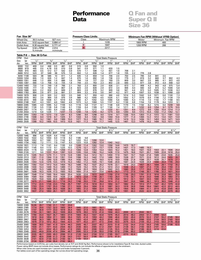
36
Fan Size 36”
Wheel Dia. 36.5 inches 927 mmInlet Area 9.52 square feet 0.884 m2
Outlet Area 8.30 square feet 0.771 m2
Tip Speed 9.56 x RPM 2.914ft./minute m/minute
Minimum Fan RPM (Without VFRB Option)Motor Minimum Fan RPM
1800 RPM 4001200 RPM 266
PerformanceData
Q Fan andSuper Q IISize 36
Table P-8 — Size 36 Q-FanCFM Out- Total Static PressureStd. let 1/4” 3/8” 1/2” 5/8” 3/4” 1” 1 1/4” 1 1/2” 1 3/4” 2”Air Vel. RPM BHP RPM BHP RPM BHP RPM BHP RPM BHP RPM BHP RPM BHP RPM BHP RPM BHP RPM BHP6000 722 409 0.4 446 0.5 481 0.6 515 0.8 550 1.06800 819 445 0.5 4.78 0.6 510 0.8 541 0.9 571 1.1 633 1.57600 915 483 0.5 512 0.7 542 0.9 570 1.1 598 1.2 651 1.6 708 2.18400 1012 523 07 549 08 575 1.0 602 1.2 628 1.4 677 1.8 725 2.2 776 2.89200 1108 564 08 586 10 611 1.2 635 1.4 659 1.6 706 2.0 750 2.5 795 3.0 841 3.5
10000 1204 605 1.0 626 1.2 647 1.4 670 1.6 692 1.8 736 2.3 779 2.7 819 3.2 860 3.7 902 4.310800 1301 648 1.2 666 1.4 686 1.6 706 1.8 727 2.0 769 2.5 809 3.0 847 3.5 885 4.1 922 4.611600 1397 690 1.4 708 1.6 725 1.8 744 2.0 763 2.3 802 2.8 840 3.3 877 3.8 912 4.4 948 5.012400 1493 733 1.6 749 1.8 766 2.1 783 2.3 800 2.6 836 3.1 873 3.7 908 4.2 943 4.8 975 5.413200 1590 777 1.9 792 2.1 807 2.4 823 2.6 839 2.9 872 3.4 906 4.0 940 4.6 973 5.2 1006 5.814000 1686 820 2.2 834 2.4 849 2.7 863 2.9 878 3.2 909 3.8 941 4.4 973 5.0 1005 5.7 1036 6.314800 1783 864 2.6 877 2.8 891 3.1 904 3.3 918 3.6 947 4.2 977 4.8 1007 5.5 1038 6.1 1068 6.815600 1879 908 2.9 920 3.2 933 3.5 946 3.7 959 4.0 986 4.6 1014 5.3 1042 5.9 1071 6.6 1100 7.316400 1975 952 3.4 964 3.6 976 3.9 988 4.2 1000 4.5 1026 5.1 1052 5.7 1079 6.4 1106 7.2 1134 7.917200 2072 996 3.8 1008 4.1 1019 4.4 1030 4.7 1042 5.0 1066 5.6 1090 6.3 1116 7.0 1142 7.7 1168 8.518000 2168 1041 4.3 1051 4.6 1062 4.9 1073 5.2 1084 5.5 1107 6.2 1130 6.8 1154 7.6 1178 8.4 1203 9.118800 2265 1085 4.9 1095 5.2 1106 5.5 1116 5.8 1127 6.1 1148 6.8 1170 7.5 1192 8.2 1215 9.0 1239 9.819600 2361 1130 5.5 1139 5.8 1149 6.1 1159 6.4 1169 6.7 1190 7.4 1211 8.1 1232 8.9 1254 9.7 1276 10.520400 2457 1174 6.1 1183 6.4 1193 6.8 1202 7.1 1212 7.4 1232 8.1 1251 8.9 1272 9.6 1293 10.4 1314 11.321200 2554 1219 6.8 1228 7.1 1237 7.5 1246 7.8 1255 8.2 1274 8.9 1293 9.6 1312 10.4 1332 11.2 1352 12.122000 2650 1263 7.6 1272 7.9 1281 8.3 1290 8.6 1298 9.0 1316 9.7 1335 10.5 1353 11.3 1372 12.1 1391 13.022800 2746 1308 8.4 1316 8.7 1325 9.1 1333 9.4 1342 9.8 1359 10.6 1377 11.4 1394 12.2 1412 13.0 1431 13.923600 2843 1353 9.2 1361 9.6 1369 10.0 1377 10.3 1385 10.7 1402 11.5 1419 12.3 1436 13.1 1453 14.0 1471 14.924400 2939 1398 10.2 1405 10.5 1413 10.9 1421 11.3 1429 11.7 1445 12.5 1461 13.3 1478 14.2 1494 15.0 1511 15.9
CFM Out- Total Static PressureStd. let 2 1/4” 2 1/2” 3” 3 1/2” 4” 4 1/2” 5” 5 1/2” 6” 6 1/2”Air Vel. RPM BHP RPM BHP RPM BHP RPM BHP RPM BHP RPM BHP RPM BHP RPM BHP RPM BHP RPM BHP12000 1445 996 5.8 1029 6.4 1100 7.912800 1542 1022 6.2 1054 6.9 1118 8.2 1185 9.813600 1638 1052 6.7 1081 7.3 1142 8.7 1202 10.2 1266 12.014400 1734 1082 7.2 1111 7.9 1167 9.3 1223 10.8 1282 12.4 1342 14.215200 1831 1113 7.8 1141 8.4 1195 9.9 1249 11.4 1302 13.0 1358 14.8 1415 16.716000 1927 1145 8.4 1172 9.1 1225 10.5 1276 12.1 1327 13.7 1378 15.4 1431 17.3 1485 19.316800 2024 1178 9.0 1204 9.7 1256 11.2 1306 12.8 1354 14.4 1403 16.2 1451 18.0 1501 19.9 1553 22.1 1606 24.417600 2120 1211 9.6 1237 10.4 1287 12.0 1335 13.6 1382 15.2 1428 17.0 1475 18.8 1521 20.7 1569 22.8 1618 25.018400 2216 1245 10.3 1270 11.1 1319 12.8 1366 14.4 1412 16.1 14S6 17.9 1501 19.7 1544 21.6 1589 23.6 1635 25.819200 2313 1281 11.0 1304 11.9 1351 13.6 1398 15.3 1442 17.0 1486 18.9 1528 20.7 1571 22.6 1612 24.6 1655 26.720000 2409 1317 11.8 1340 12.6 1385 14.4 1430 16.3 1473 18.0 1516 19.9 1558 21.8 1598 23.7 1639 25.7 1679 27.720800 2506 1354 12.6 1376 13.5 1419 15.3 1462 17.2 1505 19.1 1546 20.9 1587 22.9 1628 24.9 1666 26.9 1705 29.021600 2602 1392 13.4 1412 14.4 1454 16.2 1496 18.2 1537 20.2 1578 22.1 1618 24.0 1657 26.1 1694 28.1 1732 30.222400 2698 1430 14.3 1449 15.3 1489 17.2 1529 19.2 1570 21.2 1610 23.3 1648 25.2 1687 27.3 1725 29.4 1760 31.523200 2795 1469 15.3 1488 16.2 1526 18.3 1564 20.3 1604 22.4 1642 24.5 1680 26.6 1717 28.6 1754 30.8 1791 33.024000 2891 1508 16.3 1526 17.3 1563 19.3 1600 21.4 1637 23.6 1675 25.7 1713 27.9 1749 30.1 1785 32.2 1821 34.424800 2987 1548 17.4 1565 18.4 1600 20.4 1636 22.6 1672 24.8 1709 27.0 1745 29.3 1781 31.5 1816 33.8 1851 35.925600 3084 1589 18.6 1605 19.6 1638 21.6 1673 23.8 1708 26.1 1743 28.4 1779 30.7 1814 33.0 1848 35.3 1882 37.526400 3180 1629 19.8 1645 20.8 1677 22.9 1710 25.1 1744 27.4 1778 29.8 1812 32.1 1847 34.5 1880 36.9 1914 39.327200 3277 1670 21.1 1686 22.1 1716 24.2 1748 26.5 1781 28.8 1814 31.2 1847 33.6 1880 36.1 1913 38.5 1946 41.028000 3373 1712 22.5 1726 23.5 1756 25.7 1787 27.9 1818 30.3 1850 32.7 1882 35.2 1914 37.7 1947 40.2 1979 42.828800 3469 1753 23.9 1767 25.0 1796 27.1 1826 29.4 1856 31.8 1887 34.3 1918 36.8 1949 39.4 198O 42.0 2012 44.529600 3566 1795 25.4 1809 26.5 1836 28.7 1865 31.0 1894 33.4 1924 35.9 1954 38.5 1984 41.1 2014 43.8 2045 46.430400 3662 1837 27.0 1850 28.1 1877 30.3 1905 32.7 1933 35.1 1961 37.6 1991 40.3 2020 42.9 2049 45.6 2079 48.3
CFM Out- Total Static PressureStd. let 7” 7 1/2” 8” 8 1/2” 9” 9 1/2” 10” 10 1/2” 11” 11 1/2”Air Vel. RPM BHP RPM BHP RPM BHP RPM BHP RPM BHP RPM BHP RPM BHP RPM BHP RPM BHP RPM BHP19000 2289 16.95 28.7 1740 31.1 1787 33.619800 2385 1714 29.6 1757 32.0 1800 34.4 1845 37.0 1891 39.720600 2481 1737 30.8 1777 33.0 1818 35.4 1860 37.9 1902 40.6 1946 43.321400 2578 1764 32.1 1801 34.2 1839 36.6 1878 39.0 1918 41.6 1958 44.3 2000 47.1 2042 50.122200 2674 1790 33.4 1827 35.7 1863 37.9 1900 40.3 1937 42.8 1976 45.4 2014 48.2 2054 51.1 2094 54.023000 2771 1818 34.8 1854 37.1 1889 39.4 1925 41.8 1959 44.2 1996 46.8 2032 49.4 2070 52.2 2107 55.2 2145 58.223800 2867 1848 36.3 1881 38.6 1916 40.9 1950 43.4 1985 45.8 2018 48.2 2053 50.9 2088 53.6 2124 56.5 2160 59.424600 2963 1878 37.9 1912 40.2 1944 42.5 1977 45.0 2011 47.5 2044 50.0 2076 52.5 2109 55.2 2143 58.0 2178 60.825400 3060 1908 39.5 1941 41.9 1974 44.3 2005 46.7 2037 49.2 2070 51.8 2102 54.4 2133 56.9 2165 59.6 2198 62.526200 3156 1939 41.1 1971 43.6 2004 46.0 2036 48.5 2065 51.0 2097 53.6 2128 56.2 2160 58.9 2191 61.727000 3253 1970 43.1 2002 45.3 2034 47.8 2065 50.4 2096 53.0 2125 55.5 2155 58.1 2186 60.9 2216 63.627800 3349 2002 44.9 2034 47.4 2064 49.7 2095 52.3 2126 55.0 2156 57.6 2184 60.2 2213 62.928600 3445 2035 46.7 2065 49.3 2096 51.9 2126 54.3 2156 57.0 2185 59.7 2215 62.429400 3542 2067 48.6 2098 51.3 2128 54.0 2157 56.4 2186 59.1 2215 61.930200 3638 2101 50.6 2130 53.3 2160 56.1 2189 58.831000 3734 2134 52.6 2164 55.4 2192 58.2Performance based on 0.075 lbs. per cubic foot density (air at 70 F and 29.92 Hg Bar). Performance shown is for installation Type B: free inlet, ducted outlet.Power rating (BHP) does not include drive losses. Performance ratings do not include the effects of appurtenances in the airstream.When inlet vanes are used increase rpm 1 percent and brake horsepower 3 percent.Fan tables cover part of fan operating range; fan curves show full operating range.
Pressure Class LimitsClass Maximum RPM
I 1228II 1647III 2217

37
PerformanceData
Q Fan andSuper Q IISize 36
Standard fans can be selected ONLY in the shaded area.Thrust restrains are to be used with fans Class 3 or motors 40 hp and up.
Minimum and Maximum Motor HP Ranges
Q Fan Size 36” Super Q Fan Size 36”
Min - Max Min - Max Min - Max Min - Max Min - MaxMotor HP Motor HP Motor HP Motor HP Motor HP
Class 1 Class 2 Class 3 Class 1 Class 2Arrangement 9 1.5 - 15 10 - 30 25 - 50 1.5 - 15 10 - 30Arrangement 1 1.5 - 15 10 - 30 25 - 75 NA NA
____ Fan RPM Line- - - Motor HP Line

38
Fan Size 40”
Wheel Dia. 40.3 inches 1022 mmInlet Area 11.56 square feet 1.074 m2
Outlet Area 10.09 square feet 0.937 m2
Tip Speed 10.54 x RPM 3.213ft./minute m/minute
Minimum Fan RPM (Without VFRB Option)Motor Minimum Fan RPM
1800 RPM 3011200 RPM 200
PerformanceData
Q Fan andSuper Q IISize 40
Table P-9 — Size 40 Q FanCFM Out- Total Static PressureStd. let 1/4” 3/8” 1/2” 5/8” 3/4” 1” 1 1/4” 1 1/2” 1 3/4” 2”Air Vel. RPM BHP RPM BHP RPM BHP RPM BHP RPM BHP RPM BHP RPM BHP RPM BHP RPM BHP RPM BHP8000 792 395 0.5 426 0.7 455 0.9 483 1.1 511 1.3 571 1.88800 872 422 0.6 450 0.8 478 1.0 505 1.2 530 1.4 582 1.99600 951 451 0.7 477 0.9 502 1.1 528 1.3 552 1.6 599 2.1 647 2.6
10400 1030 481 0.8 504 1.1 528 1.3 552 1.5 575 1.7 619 2.2 662 2.8 707 3.411200 1110 512 1.0 532 1.2 554 1.4 576 1.7 598 1.9 641 2.5 681 3.0 721 3.6 763 4.312000 1189 543 1.1 562 1.4 582 1.6 602 1.9 623 2.2 663 2.7 701 3.2 739 3.9 777 4.5 816 5.212800 1268 574 1.3 592 1.6 610 1.8 629 2.1 648 2.4 687 3.0 724 3.5 759 4.1 795 4.8 830 5.513600 1347 606 1.5 622 1.8 639 2.0 657 2.3 675 2.6 711 3.2 747 3.8 781 4.5 814 5.1 848 5.814400 1427 638 1.8 653 2.0 669 2.3 685 2.6 702 2.9 736 3.5 771 4.2 804 4.8 836 5.5 867 6.215200 1506 670 2.0 684 2.3 699 2.5 714 2.8 730 3.1 762 3.8 795 4.5 827 5.2 858 5.9 888 6.616000 1585 702 2.3 716 2.6 730 2.8 744 3.1 759 3.5 789 4.1 820 4.9 851 5.6 881 6.3 910 7.016800 1665 735 2.6 748 2.9 761 3.2 774 3.5 788 3.8 817 4.5 846 5.2 876 6.0 905 6.8 933 7.517600 1744 767 2.9 780 3.2 792 3.5 805 3.8 818 4.2 845 4.9 872 5.6 901 6.4 929 7.2 957 8.018400 1823 800 3.3 812 3.6 824 3.9 836 4.2 848 4.6 873 5.3 900 6.1 926 6.9 954 7.7 980 8.519200 1902 833 3.7 844 4.0 855 4.3 867 4.7 878 5.0 902 5.7 927 6.5 953 7.4 979 8.2 1005 9.120000 1982 866 4.1 876 4.4 887 4.8 898 5.1 909 5.5 932 6.2 956 7.0 980 7.9 1005 8.8 1030 9.720800 2061 899 4.6 909 4.9 919 5.3 930 5.6 940 6.0 962 6.7 985 7.5 1008 8.4 1031 9.3 1055 10.321600 2140 932 5.1 942 5.4 952 5.8 962 6.1 972 6.5 993 7.3 1014 8.1 1036 9.0 1059 9.9 1081 10.922400 2220 965 5.6 974 6.0 984 6.3 994 6.7 1003 7.1 1023 7.9 1044 8.7 1065 9.6 1086 10.6 1108 11.523200 2299 998 6.2 1007 6.5 1016 6.9 1026 7.3 1035 7.7 1054 8.5 1074 9.4 1094 10.3 1114 11.2 1136 12.224000 2378 1031 6.8 1040 7.2 1049 7.5 1058 7.9 1067 8.3 1085 9.2 1104 10.0 1123 11.0 1143 11.9 1163 13.024800 2457 1064 7.4 1073 7.8 1081 8.2 1090 8.6 1099 9.0 1117 9.8 1135 10.8 1153 11.7 1172 12.7 1191 13.725600 2537 1098 8.1 1106 8.5 1114 8.9 1123 9.3 1131 9.8 1148 10.6 1165 11.5 1183 12.5 1201 13.5 1220 14.526400 2616 1131 8.9 1139 9.3 1147 9.7 1155 10.1 1163 10.5 1180 11.4 1196 12.4 1214 13.3 1231 14.3 1249 15.4
CFM Out- Total Static PressureStd. let 2 1/4” 2 1/2” 3” 3 1/2” 4” 4 1/2” 5” 5 1/2” 6” 6 1/2”Air Vel. RPM BHP RPM BHP RPM BHP RPM BHP RPM BHP RPM BHP RPM BHP RPM BHP RPM BHP RPM BHP15000 1486 913 7.2 942 8.0 1004 9.7 1069 11.715800 1565 933 7.7 962 8.5 1019 10.1 1078 12.016600 1645 956 8.2 982 9.0 1037 10.7 1091 12.5 1149 14.617400 1724 978 8.7 1005 9.5 1056 11.2 1107 13.0 1161 15.0 1216 17.318200 1803 1001 9.2 1027 10.1 1076 11.8 1126 13.6 1175 15.6 1227 17.7 1280 20.119000 1883 1024 9.8 1049 10.6 1099 12.4 1146 14.3 1192 16.2 1241 18.3 1290 20.7 1342 23.219800 1962 1049 10.4 1073 11.3 1121 13.1 1166 15.0 1212 17.0 1257 19.0 1304 21.3 1351 23.7 1401 26.420600 2041 1073 11.0 1097 12.0 1143 13.8 1189 15.7 1232 17.7 1276 19.8 1319 22.0 1364 24.4 1410 27.0 1458 29.721400 2120 1098 11.7 1121 12.6 1167 14.6 1211 16.5 1253 18.5 1295 20.7 1338 22.9 1379 25.2 1423 27.7 1467 30.422200 2200 1124 12.4 1146 13.3 1191 15.4 1234 17.3 1276 19.4 1316 21.5 1357 23.8 1396 26.0 1438 28.5 1480 31.123000 2279 1150 13.1 1171 14.1 1215 16.2 1257 18.3 1298 20.3 1338 22.5 1377 24.7 1416 27.1 1454 29.4 1494 32.023800 2358 1177 13.8 1198 14.9 1240 17.0 1281 19.2 1321 21.3 1360 23.5 1397 25.7 1436 28.1 1474 30.6 1511 33.024600 2438 1204 14.6 1224 15.7 1265 17.8 1305 20.1 1344 22.3 1383 24.5 1420 26.9 1456 29.2 1493 31.7 1530 34.225400 2517 1232 15.4 1251 16.5 1290 18.8 1329 21.0 1368 23.4 1405 25.6 1442 28.0 1479 30.4 1513 32.8 1549 35.426200 2596 1260 16.2 1279 17.4 1316 19.7 1354 22.0 1392 24.4 1429 26.8 1465 29.1 1501 31.6 1534 34.0 1569 36.627000 2675 1288 17.1 1306 18.3 1343 20.6 1379 23.1 1416 25.5 1453 28.0 1488 30.3 1523 32.8 1557 35.4 1590 37.927800 2755 1317 18.1 1334 19.2 1370 21.7 1405 24.1 1441 26.6 1477 29.2 1512 31.7 1546 34.1 1579 36.7 1613 39.428600 2834 1346 19.1 1363 20.2 1397 22.7 1431 25.2 1466 27.8 1501 30.4 1535 33.0 1569 35.4 1602 38.1 1635 40.829400 2913 1376 20.1 1392 21.3 1425 23.8 1458 26.4 1492 29.0 1526 31.6 1560 34.3 1593 37.0 1625 39.5 1657 42.230200 2993 1406 21.3 1421 22.4 1453 24.9 1485 27.6 1518 30.2 1551 32.9 1584 35.7 1616 38.4 1649 41.2 1680 43.831000 3072 1436 22.4 1451 23.6 1481 26.1 1513 28.8 1544 31.5 1576 34.3 1609 37.0 1641 39.9 1672 42.7 1703 45.431800 3151 1466 23.6 1480 24.8 1510 27.4 1541 30.1 1571 32.8 1602 35.6 1634 38.5 1665 41.4 1696 44.3 1727 47.232600 3230 1496 24.9 1511 26.1 1539 28.7 1568 31.3 1599 34.2 1629 37.1 1659 40.0 1690 42.9 1720 45.9 1750 48.933400 3310 1527 26.2 1541 27.5 1568 30.0 1597 32.7 1626 35.6 1656 38.6 1685 41.5 1715 44.5 1745 47.5 1774 50.6
CFM Out- Total Static PressureStd. let 7” 7 1/2” 8” 8 1/2” 9” 9 1/2” 10” 10 1/2” 11” 11 1/2”Air Vel. RPM BHP RPM BHP RPM BHP RPM BHP RPM BHP RPM BHP RPM BHP RPM BHP RPM BHP RPM BHP23000 2279 1535 34.8 1576 37.7 1619 40.723800 2358 1549 35.7 1589 38.5 1629 41.5 1670 44.724600 2438 1566 36.8 1603 39.5 1641 42.5 1680 45.6 1720 48.825400 2517 1585 38.1 1619 40.7 1655 43.5 1692 46.6 1730 49.8 1768 53.1 1807 56.626200 2596 1604 39.3 1638 42.0 1672 44.7 1707 47.7 1743 50.8 1779 54.1 1816 57.5 1854 61.127000 2675 1623 40.6 1657 43.4 1690 46.2 1723 49.0 1757 52.1 1792 55.3 1827 58.6 1862 62.1 1899 65.727800 2755 1644 42.0 1677 44.8 1709 47.6 1740 50.4 1773 53.4 1806 56.6 1840 59.8 1874 63.3 1908 66.8 1944 70.528600 2834 1667 43.5 1697 46.2 1729 49.1 1760 52.1 1791 54.9 1823 58.0 1855 61.2 1887 64.6 1921 68.1 1954 71.729400 2913 1689 45.0 1718 47.8 1749 50.7 1780 53.6 1811 56.7 1840 59.6 1871 62.7 1902 66.1 1934 69.5 1966 73.030200 2993 1711 46.6 1742 49.5 1770 52.3 1800 55.3 1830 58.3 1860 61.4 1890 64.6 1919 67.7 1949 71.0 1980 74.531000 3072 1733 48.2 1764 51.1 1793 54.1 1821 57.0 1851 60.0 1880 63.2 1909 66.4 1938 69.7 1966 72.831800 3151 1756 49.9 1786 52.8 1815 55.8 1844 58.9 1871 61.8 1900 65.0 1928 68.2 1957 71.5 1985 74.932600 3230 1780 51.8 1809 54.6 1838 57.6 1866 60.7 1895 63.9 1921 66.9 1949 70.1 1976 73.433400 3310 1804 53.6 1832 56.4 1860 59.5 1889 62.6 1916 65.8 1944 69.0 1969 72.134200 3389 1828 55.5 1856 58.6 1883 61.5 1911 64.6 1939 67.8 1966 71.1 1993 74.435000 3468 1852 57.3 1880 60.5 1907 63.7 1934 66.6 1961 69.9 1988 73.2Performance based on 0.075 lbs. per cubic foot density (air at 70 F and 29.92 Hg Bar). Performance shown is for installation Type B: free inlet, ducted outlet.Power rating (BHP) does not include drive losses. Performance ratings do not include the effects of appurtenances in the airstream.When inlet vanes are used increase rpm 1 percent and brake horsepower 3 percent.Fan tables cover part of fan operating range; fan curves show full operating range.
Pressure Class LimitsClass Maximum RPM
I 1110II 1492III 2050

39
PerformanceData
Q Fan andSuper Q IISize 40
Standard fans can be selected ONLY in the shaded area.Thrust restrains are to be used with fans Class 3 or motors 40 hp and up.
Minimum and Maximum Motor HP Ranges
Q Fan Size 40” Super Q Fan Size 40”
Min - Max Min - Max Min - Max Min - Max Min - MaxMotor HP Motor HP Motor HP Motor HP Motor HP
Class 1 Class 2 Class 3 Class 1 Class 2Arrangement 9 1.5 - 15 10 - 40 30 - 50 1.5 - 15 10 - 40Arrangement 1 1.5 - 15 10 - 40 30 - 75 NA NA
____ Fan RPM Line- - - Motor HP Line

40
Fan Size 44”
Wheel Dia. 44.5 inches 1130 mmInlet Area 14.14 square feet 1.314 m2
Outlet Area 12.33 square feet 1.145 m2
Tip Speed 11.65 x RPM 3.551ft./minute m/minute
Minimum Fan RPM (Without VFRB Option)Motor Minimum Fan RPM
1800 RPM 2891200 RPM 192
PerformanceData
Q Fan andSuper Q IISize 44
Table P-10 — Size 44 Q-FanCFM Out- Total Static PressureStd. let 1/4” 3/8” 1/2” 5/8” 3/4” 1” 1 1/4” 1 1/2” 1 3/4” 2”Air Vel. RPM BHP RPM BHP RPM BHP RPM BHP RPM BHP RPM BHP RPM BHP RPM BHP RPM BHP RPM BHP9000 729 335 0.5 364 0.7 392 1.0 420 1.2 451 1.5
10000 811 360 0.7 385 0.9 412 1.1 437 1.3 463 1.6 517 2.211000 892 386 0.8 409 1.0 433 1.2 457 1.5 480 1.8 526 2.412000 973 413 0.9 434 1.2 456 1.4 478 1.7 499 2.0 542 2.6 585 3.313000 1054 440 1.1 460 1.3 480 1.6 500 1.9 520 2.2 559 2.8 598 3.5 639 4.214000 1135 468 1.2 487 1.5 505 1.8 523 2.1 542 2.4 580 3.0 616 3.7 652 4.5 691 5.4 729 6.315000 1216 496 1.4 514 1.7 531 2.0 548 2.4 565 2.7 600 3.3 635 4.0 669 4.8 702 5.6 738 6.516000 1297 525 1.7 541 2.0 557 2.3 574 2.6 590 3.0 622 3.7 655 4.4 687 5.2 719 6.0 750 6.817000 1378 554 1.9 569 2.2 584 2.6 600 2.9 615 3.3 645 4.0 676 4.7 707 5.5 736 6.4 767 7.318000 1459 583 2.2 597 2.5 612 2.9 626 3.2 641 3.6 669 4.4 698 5.2 727 6.0 756 6.8 784 7.719000 1540 612 2.5 626 2.9 639 3.2 653 3.6 667 4.0 694 4.8 721 5.6 748 6.4 776 7.3 804 8.220000 1622 641 2.9 654 3.2 667 3.6 681 4.0 694 4.4 719 5.2 745 6.1 771 6.9 797 7.8 824 8.721000 1703 671 3.2 683 3.6 696 4.0 708 44 721 4.8 745 5.7 770 6.6 794 7.4 819 8.4 844 9.322000 1784 701 3.6 712 4.0 724 4.4 736 4.8 748 5.3 772 6.2 795 7.1 818 8.0 842 9.0 866 9.923000 1865 730 4.1 742 4.5 753 4.9 764 5.3 776 5.8 798 6.7 821 7.7 843 8.6 865 9.6 888 10.624000 1946 760 4.6 771 5.0 782 5.4 793 5.9 804 6.3 825 7.3 847 8.2 869 9.3 890 10.3 911 11.325000 2027 790 5.1 800 5.5 811 6.0 821 6.4 832 6.9 853 7.9 873 8.9 894 9.9 915 11.0 935 12.026000 2108 820 5.7 830 6.1 840 6.6 850 7.0 860 7.5 880 8.5 900 9.5 920 10.6 940 11.7 960 12.827000 2189 850 6.3 860 6.7 869 7.2 879 7.7 889 8.2 908 9.2 927 10.3 947 11.4 966 12.5 985 13.728000 2270 880 6.9 889 7.4 899 7.9 908 8.4 917 8.9 936 9.9 955 11.0 973 12.2 992 13.3 1010 14.529000 2351 910 7.6 919 8.1 928 8.6 937 9.1 946 9.6 964 10.7 982 11.8 1000 13.0 1018 14.2 1036 15.430000 2433 941 8.4 949 8.9 958 9.4 966 9.9 975 10.4 992 11.5 1010 12.7 1027 13.9 1045 15.1 1062 16.331000 2514 971 9.2 979 9.7 987 10.2 996 10.7 1004 11.3 1021 12.4 1038 13.6 1055 14.8 1072 16.0 1088 17.332000 2595 1001 10.0 1009 10.6 1017 11.1 1025 11.6 1033 12.2 1050 13.4 1066 14.6 1082 15.8 1099 17.1 1115 18.4
CFM Out- Total Static PressureStd. let 2 1/4” 2 1/2” 3” 3 1/2” 4” 4 1/2” 5” 5 1/2” 6” 6 1/2”Air Vel. RPM BHP RPM BHP RPM BHP RPM BHP RPM BHP RPM BHP RPM BHP RPM BHP RPM BHP RPM BHP16000 1297 784 7.8 818 8.917000 1378 796 8.2 828 9.218000 1459 813 8.7 841 9.6 901 11.919000 1540 830 9.2 857 10.2 911 12.3 969 14.820000 1622 849 9.7 874 10.7 925 12.8 978 15.2 1033 18.021000 1703 869 10.3 893 11.3 942 13.5 990 15.7 1043 18.5 1094 21.322000 1784 890 10.9 914 12.0 960 14.1 1005 16.4 1053 18.9 1103 21.923000 1865 911 11.6 934 12.6 978 14.9 1023 17.2 1067 19.6 1113 22.4 1161 25.524000 1946 933 12.3 955 13.4 999 15.6 1041 18.0 1083 20.5 1126 23.1 1170 26.0 1216 29.425000 2027 956 13.1 977 14.2 1019 16.4 1060 18.9 1101 21.4 1141 23.9 1182 26.8 1225 29.9 1270 33.426000 2108 979 13.9 999 15.0 1040 17.3 1080 19.8 1119 22.3 1158 25.0 1197 27.7 1237 30.7 1279 34.0 1322 37.627000 2189 1004 14.8 1023 15.9 1061 18.3 1101 20.7 1139 23.3 1176 26.0 1214 28.9 1251 31.7 1290 34.8 1331 38.428000 2270 1029 15.7 1047 16.8 1084 19.3 1122 21.7 1159 24.4 1195 27.1 1231 30.0 1268 32.9 1304 35.8 1342 39.229000 2351 1054 16.6 1072 17.9 1107 20.3 1143 22.9 1180 25.5 1215 28.3 1250 31.1 1285 34.1 1320 37.2 1355 40.330000 2433 1079 17.6 1096 18.9 1130 21.4 1165 24.0 1201 26.6 1235 29.4 1270 32.4 1303 35.4 1337 38.5 1370 41.531000 2514 1105 18.6 1122 19.9 1154 22.5 1188 25.2 1222 28.0 1256 30.7 1290 33.7 1322 36.7 1355 39.9 1388 43.132000 2595 1131 19.7 1147 21.0 1180 23.8 1211 26.4 1244 29.2 1277 32.0 1310 35.0 1342 38.1 1373 41.3 1405 44.533000 2676 1157 20.8 1173 22.2 1205 25.0 1235 27.7 1267 30.6 1298 33.5 1331 36.4 1362 39.5 1394 42.8 1424 46.034000 2757 1184 22.0 1199 23.4 1230 26.3 1260 29.2 1290 32.0 1321 35.0 1352 37.9 1383 41.1 1414 44.3 1443 47.635000 2838 1211 23.2 1226 24.6 1255 27.6 1285 30.6 1314 33.5 1343 36.5 1373 39.6 1404 42.6 1434 45.9 1464 49.336000 2919 1238 24.5 1252 25.9 1281 29.0 1310 32.0 1338 35.0 1367 38.1 1396 41.2 1425 44.3 1455 47.6 1484 51.037000 3000 1265 25.8 1279 27.3 1307 30.4 1335 33.5 1363 36.7 1390 39.7 1419 42.9 1447 46.2 1476 49.4 1504 52.838000 3081 1293 27.2 1306 28.8 1334 31.9 1361 35.1 1388 38.3 1415 41.4 1442 44.7 1469 48.0 1497 51.4 1525 54.739000 3163 1320 28.7 1334 30.3 1360 33.4 1387 36.7 1413 40.0 1440 43.3 1466 46.5 1492 49.9 1519 53.4 1547 56.7
CFM Out- Total Static PressureStd. let 7” 7 1/2” 8” 8 1/2” 9” 9 1/2” 10” 10 1/2” 11” 11 1/2”Air Vel. RPM BHP RPM BHP RPM BHP RPM BHP RPM BHP RPM BHP RPM BHP RPM BHP RPM BHP RPM BHP28000 2270 1381 42.9 1420 46.7 1458 50.629000 2351 1392 43.7 1430 47.6 1468 51.6 1505 55.630000 2433 1405 44.9 1440 48.5 1476 52.3 1514 56.6 1550 60.731000 2514 1420 46.2 1453 49.7 1488 53.4 1522 57.4 1559 61.8 1594 66.032000 2595 1437 47.9 1468 51.1 1501 54.7 1534 58.6 1568 62.6 1603 67.2 1637 71.533000 2676 1455 49.5 1486 52.9 1516 56.2 1547 59.9 1579 63.9 1612 68.1 1646 72.734000 2757 1473 51.1 1503 54.6 1533 58.2 1562 61.5 1593 65.4 1624 69.4 1655 73.735000 2838 1492 52.7 1521 56.3 1550 59.9 1580 63.6 1608 67.1 1637 71.036000 2919 1512 54.5 1540 58.1 1568 61.7 1597 65.5 1625 69.3 1652 72.837000 3000 1532 56.3 1560 60.0 1587 63.6 1615 67.4 1642 71.338000 3081 1553 58.2 1580 61.9 1607 65.6 1633 69.4 1660 73.339000 3163 1574 60.2 1601 63.9 1627 67.7 1652 71.440000 3244 1595 62.3 1621 66.0 1647 69.8 1673 73.741000 3325 1616 64.7 1642 68.2 1668 72.042000 3406 1638 66.9 1664 70.5 1689 74.343000 3487 1661 69.3 1685 73.1Performance based on 0.075 lbs. per cubic foot density (air at 70 F and 29.92 Hg Bar). Performance shown is for installation Type B: free inlet, ducted outlet.Power rating (BHP) does not include drive losses. Performance ratings do not include the effects of appurtenances in the airstream.When inlet vanes are used increase rpm 1 percent and brake horsepower 3 percent.Fan tables cover part of fan operating range; fan curves show full operating range.
Pressure Class LimitsClass Maximum RPM
I 1070II 1352III 1922

41
PerformanceData
Q Fan andSuper Q IISize 44
Standard fans can be selected ONLY in the shaded area.Thrust restrains are to be used with fans Class 3 or motors 40 hp and up.
Minimum and Maximum Motor HP Ranges
Q Fan Size 44” Super Q Fan Size 44”
Min - Max Min - Max Min - Max Min - Max Min - MaxMotor HP Motor HP Motor HP Motor HP Motor HP
Class 1 Class 2 Class 3 Class 1 Class 2Arrangement 9 3 - 20 15 - 40 40 - 50 3 - 20 15 - 40Arrangement 1 3 - 20 15 - 40 40 - 75 NA NA
____ Fan RPM Line- - - Motor HP Line

42
Fan Size 49”
Wheel Dia. 49.0 inches 1245 mmInlet Area 14.96 square feet 1.390 m2
Outlet Area 14.96 square feet 1.390 m2
Tip Speed 12.83 x RPM 3.911ft./minute m/minute
Minimum Fan RPM (Without VFRB Option)Motor Minimum Fan RPM
1800 RPM 3011200 RPM 201
PerformanceData
Q FanSize 49
Table P-11 — Size 49 Q-FanCFM Out- Total Static PressureStd. let 1/4” 3/8” 1/2” 5/8” 3/4” 1” 1 1/4” 1 1/2” 1 3/4” 2”Air Vel. RPM BHP RPM BHP RPM BHP RPM BHP RPM BHP RPM BHP RPM BHP RPM BHP RPM BHP RPM BHP13000 868 353 1.0 376 1.2 400 1.6 425 1.9 451 2.3•14000 935 373 1.1 395 1.4 417 1.7 439 2.1 463 2.415000 1002 394 1.3 414 1.6 435 1.9 455 2.3 476 2.6 521 3.5•160001069 415 1.4 434 1.8 453 2.1 472 2.5 492 2.9 532 3.717000 1136 437 1.6 454 2.0 472 2.4 490 2.7 508 3.1 545 4.0 585 4.918000 1203 458 1.9 475 2.2 492 2.6 509 3.0 525 3.4 560 4.3 596 5.219000 1270 480 2.1 496 2.5 511 2.9 528 3.3 544 3.7 576 4.6 610 5.6 645 6.620000 1336 503 2.4 517 2.8 532 3.2 547 3.6 563 4.1 593 4.9 624 5.9 657 7.0 691 8.121000 1403 525 2.7 539 3.1 552 3.5 567 3.9 582 4.4 611 5.3 640 6.3 671 7.4 702 8.522000 1470 548 3.0 560 3.4 574 3.9 587 4.3 601 4.8 629 5.8 657 6.7 685 7.8 715 9.0 745 10.223000 1537 570 3.4 582 3.8 595 4.2 608 4.7 621 5.2 648 6.2 674 7.2 701 8.3 729 9.5 757 10.7•240001604 593 3.7 605 4.2 616 4.6 629 5.1 641 5.6 667 6.7 692 7.7 718 8.8 744 10.0 771 11.225000 1671 616 4.2 627 4.6 638 5.1 650 5.6 662 6.1 686 7.2 711 8.3 735 9.3 760 10.5 785 11.826000 1737 639 4.6 649 5.1 660 5.6 671 6.1 682 6.6 706 7.7 730 8.8 753 9.9 777 11.1 801 12.427000 1804 662 5.1 672 5.6 682 6.1 693 6.6 704 7.1 726 8.2 749 9.4 772 10.6 794 11.8 817 13.028000 1871 685 5.6 695 6.1 704 6.6 715 7.1 725 7.7 746 8.8 768 10.0 790 11.3 812 12.5 834 13.729000 1938 708 6.1 717 6.6 727 7.2 737 7.7 746 8.3 767 9.5 788 10.7 809 12.0 830 13.2 851 14.530000 2005 731 6.7 740 7.2 749 7.8 759 8.3 768 8.9 788 10.1 808 11.4 828 12.7 849 14.0 869 15.331000 2072 754 7.3 763 7.9 772 8.4 781 9.0 790 9.6 809 10.8 828 12.1 848 13.5 868 14.8 888 16.232000 2139 777 8.0 786 8.6 794 9.1 803 9.7 812 10.3 830 11.6 848 12.9 867 14.2 887 15.6 906 17.133000 2205 801 8.7 809 9.3 817 9.9 826 10.5 834 11.1 851 12.4 869 13.7 887 15.1 906 16.5 925 18.034000 2272 824 9.4 832 10.0 840 10.6 848 11.2 856 11.9 873 13.2 890 14.5 908 15.9 926 17.4 944 18.935000 2339 847 10.2 855 10.8 863 11.4 871 12.1 879 12.7 895 14.1 911 15.4 928 16.9 946 18.4 964 19.936000 2406 871 11.0 878 11.7 886 12.3 893 13.0 901 13.6 917 15.0 933 16.4 949 17.8 966 19.3 983 20.9
CFM Out- Total Static PressureStd. let 2 1/4” 2 1/2” 3” 3 1/2” 4” 4 1/2” 5” 5 1/2” 6” 6 1/2”Air Vel. RPM BHP RPM BHP RPM BHP RPM BHP RPM BHP RPM BHP RPM BHP RPM BHP RPM BHP RPM BHP23000 1537 787 12.024000 1604 798 12.6 827 13.925000 1671 811 13.1 838 14.526000 1737 825 13.8 851 15.2 903 18.127000 1804 840 14.4 864 15.8 913 18.828000 1871 856 15.1 879 16.5 925 19.5 974 22.829000 1938 873 15.8 894 17.3 939 20.3 985 23.630000 2005 890 16.6 910 18. 1 953 21.2 996 24.4 1042 27.931000 2072 907 17.5 927 18.9 968 22.0 1009 25.3 1053 28.832000 2139 925 18.4 944 19.8 983 22.9 1023 26.3 1064 29.7 1107 33.533000 2205 944 19.4 962 20.8 999 23.9 1038 27.3 1077 30.8 1118 34.534000 2272 962 20.4 980 21.9 1016 24.9 1053 28.3 1091 31.9 1129 35.6 1170 39.535000 2339 981 21.4 999 23.0 1033 26.0 1069 29.4 1105 33.0 1143 36.8 1181 40.6 1221 44.836000 2406 1000 22.5 1017 24.1 1051 27.2 1085 30.5 1120 34.2 1156 38.0 1192 41.9 1230 46.037000 2473 1020 23.6 1036 25.2 1069 28.4 1102 31.7 1136 35.4 1171 39.2 1206 43.2 1242 47.338000 2540 1039 24.8 1055 26.4 1088 29.8 1120 33.0 1152 36.6 1186 40.5 1220 44.5 1254 48.639000 2606 1058 25.9 1075 27.6 1106 31.1 1137 34.4 1169 38.0 1201 41.9 1234 45.940000 2673 1078 27.1 1094 28.9 1125 32.4 1155 35.8 1186 39.4 1217 43.3 1249 47.441000 2740 1099 28.4 1114 30.2 1144 33.8 1174 37.5 1203 40.9 1234 44.8 1264 48.942000 2807 1119 29.8 1133 31.6 1163 35.3 1193 39.0 1221 42.5 1251 46.443000 2874 1140 31.2 1154 33.0 1183 36.8 1211 40.6 1240 44.3 1268 48.044000 2941 1160 32.6 1174 34.5 1202 38.3 1230 42.2 1258 46.145000 3008 1181 34.2 1195 36.0 1222 39.8 1250 43.846000 3074 1202 35.7 1215 37.6 1241 41.5 1269 45.5Performance based on 0.075 lbs. per cubic foot density (air at 70 F and 29.92 Hg Bar).Performance shown is for installation Type B: free inlet, ducted outlet.Power rating (BHP) does not include drive losses.Performance ratings do not include the effects of appurtenances in the airstream.When inlet vanes are used increase rpm 1 percent and brake horsepower 3 percent.Fan tables cover part of fan operating range; fan curves show full operating range.
Pressure Class LimitsClass Maximum RPM
I 949II 1274

43
PerformanceData
Q FanSize 49
Standard fans can be selected ONLY in the shaded area.Thrust restrains are to be used with fans Class 3 or motors 40 hp and up.Super Q II fans are NOT available in size 49.Horizontal fans only, for vertical units contact marketing in Lexington.
Minimum and Maximum Motor HP Ranges
Q Fan Size 49” Super Q Fan Size 49”
Min - Max Min - Max Min - Max Min - Max Min - MaxMotor HP Motor HP Motor HP Motor HP Motor HP
Class 1 Class 2 Class 3 Class 1 Class 2Arrangement 9 2 - 20 20 - 50 — NA NAArrangement 1 — — — NA NA
____ Fan RPM Line- - - Motor HP Line

44
Pressure Class LimitsClass Maximum RPM
I 857II 1151
Fan Size 54”
Wheel Dia. 54.3 inches 1378 mmInlet Area 18.37 square feet 1.707 m2
Outlet Area 18.37 square feet 1.707 m2
Tip Speed 14.20 x RPM 4.328ft./minute m/minute
Minimum Fan RPM (Without VFRB Option)Motor Minimum Fan RPM
1800 RPM 2921200 RPM 195
PerformanceData
Q FanSize 54
Table P-12 — Size 54 Q-FanCFM Out- Total Static PressureStd. let 1/4” 3/8” 1/2” 5/8” 3/4” 1” 1 1/4” 1 1/2” 1 3/4” 2”Air Vel. RPM BHP RPM BHP RPM BHP RPM BHP RPM BHP RPM BHP RPM BHP RPM BHP RPM BHP RPM BHP16200 881 323 1.2 344 1.6 365 1.9 387 2.4 410 2.817600 958 344 1.4 363 1.8 382 2.2 402 2.6 422 3.119000 1034 365 1.7 383 2.1 401 2.5 419 2.9 437 3.4 475 4.420400 1110 387 1.9 403 2.3 420 2.8 437 3.2 454 3.7 488 4.821800 1186 410 2.2 425 2.7 440 3.1 456 3.6 471 4.1 503 5.2 536 6.323200 1262 432 2.6 446 3.0 460 3.5 475 4.0 490 4.5 519 5.6 550 6.8 582 8.124600 1339 455 3.0 468 3.4 481 3.9 495 4.5 509 5.0 537 6.1 565 7.3 594 8.6 625 10.026000 1415 479 3.4 491 3.9 503 4.4 516 4.9 529 5.5 555 6.6 581 7.8 608 9.2 636 10.6 666 12.127400 1491 502 3.8 513 4.3 525 4.9 537 5.4 549 6.0 574 7.2 599 8.4 624 9.8 650 11.2 677 12.728800 1567 525 4.3 536 4.9 547 5.4 558 6.0 570 6.6 594 7.9 617 9.1 641 10.5 665 11.9 690 13.530200 1643 549 4.9 559 5.5 569 6.0 580 6.6 591 7.2 613 8.6 636 9.9 658 11.2 681 12.7 705 14.231600 1720 572 5.5 582 6.1 592 67 602 7.3 612 7.9 633 9.3 655 10.7 676 12.0 698 13.5 720 15.033000 1796 596 6.2 605 6.8 615 7.4 624 8.0 634 8.7 654 10.0 675 11.5 696 12.9 716 14.4 737 15.934400 1872 620 6.9 629 7.5 638 8.1 647 8.8 656 9.5 675 10.9 695 12.4 715 13.9 734 15.3 754 16.935800 1948 644 7.7 652 8.3 661 8.9 669 9.6 678 10.3 696 11.8 715 13.3 734 14.9 753 16.4 772 17.937200 2025 668 8.5 676 9.1 684 9.8 692 10.5 701 11.2 718 12.7 736 14.2 754 15.9 773 17.5 791 19.238600 2101 691 9.4 699 10.1 707 10.8 715 11.5 723 12.2 740 13.7 757 15.3 775 17.0 792 18.7 810 20.440000 2177 715 10.3 723 11.0 731 11.7 738 12.5 746 13.2 762 14.8 778 16.4 795 18.1 812 19.9 829 21.641400 2253 739 11.4 747 12.1 754 12.8 761 13.6 769 14.3 784 15.9 800 17.6 816 19.3 833 21.1 849 22.942800 2329 763 12.4 770 13.2 778 13.9 785 14.7 792 15.5 807 17.1 822 18.8 837 20.6 853 22.4 869 24.344200 2406 788 13.6 794 14.4 801 15.1 808 15.9 815 16.8 829 18.4 844 20.2 858 21.9 873 23.8 889 25.745600 2482 812 14.8 818 15.6 825 16.4 831 17.2 838 18.1 852 19.8 866 21.5 880 23.4 894 25.3 909 27.247000 2558 836 16.1 842 17.0 849 17.8 855 18.6 862 19.5 875 21.2 888 23.0 902 24.9 916 26.8 930 28.848400 2634 860 17.5 866 18.4 872 19.2 879 20.1 885 20.9 898 22.7 911 24.6 924 26.5 937 28.4 951 30.4
CFM Out- Total Static PressureStd. let 2 1/4” 2 1/2” 3” 3 1/2” 4” 4 1/2” 5” 5 1/2” 6” 6 1/2”Air Vel. RPM BHP RPM BHP RPM BHP RPM BHP RPM BHP RPM BHP RPM BHP RPM BHP RPM BHP RPM BHP29000 1578 717 15.2 744 16.930400 1654 730 16.0 755 17.731800 1731 745 16.8 767 18.5 815 22.233200 1807 760 17.7 782 19.5 826 23.134600 1883 777 18.7 797 20.5 838 24.2 882 28.236000 1959 794 19.8 813 21.6 852 25.3 893 29.337400 2035 811 20.9 830 22.7 867 26.5 906 30.5 946 34.838800 2112 830 22.2 847 23.9 883 27.7 920 31.8 957 36.1 997 40.640200 2188 849 23.6 865 25.2 900 29.0 935 33.2 970 37.5 1007 42.041600 2264 868 25.0 884 26.8 917 30.5 950 34.6 985 39.0 1019 43.5 1056 48.343000 2340 888 26.4 903 28.3 935 32.0 967 36.1 999 40.6 1033 45.2 1067 49.9 1103 55.044400 2416 907 27.9 923 29.8 953 33.6 984 37.7 1015 42.2 1047 46.9 1080 51.6 1113 56.745800 2493 927 29.4 942 31.5 972 35.5 1001 39.5 1032 43.9 1062 48.6 1094 53.5 1125 58.547200 2569 948 31.1 962 33.1 991 37.3 1019 41.3 1048 45.8 1078 50.5 1108 55.448600 2645 968 32.7 982 34.9 1010 39.2 1038 43.3 1066 47.7 1094 52.4 1123 57.450000 2721 988 34.5 1002 36.7 1030 41.1 1057 45.5 1084 49.8 1111 54.5 1139 59.551400 2798 1010 36.4 1023 38.6 1050 43.1 1076 47.7 1102 52.0 1129 56.752800 2874 1031 38.4 1043 40.6 1070 45.2 1095 49.9 1121 54.5 1146 59.054200 2950 1052 40.4 1064 42.7 1090 47.4 1115 52.1 1140 56.955600 3026 1074 42.6 1086 44.8 1110 49.5 1135 54.557000 3102 1096 44.8 1107 47.1 1130 51.958400 3179 1118 47.1 1129 49.5 1151 54.359800 3255 1140 49.5 1151 51.9Performance based on 0.075 lbs. per cubic foot density (air at 70 F and 29.92 Hg Bar).Performance shown is for installation Type B: free inlet, ducted outlet.Power rating (BHP) does not include drive losses.Performance ratings do not include the effects of appurtenances in the airstream.When inlet vanes are used increase rpm 1 percent and brake horsepower 3 percent.Fan tables cover part of fan operating range; fan curves show full operating range.

45
PerformanceData
Q FanSize 54
Standard fans can be selected ONLY in the shaded area.Thrust restrains are to be used with fans Class 3 or motors 40 hp and up.Super Q fans are NOT available in size 54.Horizontal fans only, for vertical units contact marketing in Lexington.
Minimum and Maximum Motor HP Ranges
Q Fan Size 54” Super Q Fan Size 54”
Min - Max Min - Max Min - Max Min - Max Min - MaxMotor HP Motor HP Motor HP Motor HP Motor HP
Class 1 Class 2 Class 3 Class 1 Class 2Arrangement 9 2 -25 20 - 60 — NA NAArrangement 1 — — — NA NA
____ Fan RPM Line- - - Motor HP Line

46
Pressure Class LimitsClass Maximum RPM
I 775II 1040
Fan Size 60”
Wheel Dia. 60.0 inches 1524 mmInlet Area 22.38 square feet 2.079 m2
Outlet Area 22.38 square feet 2.079 m2
Tip Speed 15.71 x RPM 4.788ft./minute m/minute
Minimum Fan RPM (Without VFRB Option)Motor Minimum Fan RPM
1800 RPM 3141200 RPM 209
PerformanceData
Q FanSize 60
Table P-13 — Size 60 Q-FanCFM Out- Total Static PressureStd. let 1/4” 3/8” 1/2” 5/8” 3/4” 1” 1 1/4” 1 1/2” 1 3/4” 2”Air Vel. RPM BHP RPM BHP RPM BHP RPM BHP RPM BHP RPM BHP RPM BHP RPM BHP RPM BHP RPM BHP19800 884 291 1.5 311 1.9 330 2.4 350 2.9 370 3.521400 956 309 1.7 327 2.2 344 2.6 362 3.2 381 3.723000 1027 327 2.0 344 2.5 360 3.0 376 3.5 393 4.1 428 5.324600 1099 346 2.3 361 2.8 376 3.3 391 3.9 407 4.4 439 5.726200 1170 365 2.6 379 3.2 393 3.7 407 4.3 422 4.9 451 6.2 482 7.627800 1242 384 3.0 397 3.6 410 4.1 424 4.7 437 5.3 464 6.7 493 8.1 523 9.729400 1313 403 3.4 415 4.0 428 4.6 441 5.2 453 5.9 479 7.2 505 8.7 532 10.331000 1385 423 3.9 434 4.5 446 5.1 458 5.7 470 6.4 494 7.8 519 9.3 544 10.9 570 12.632600 1456 442 4.4 453 5.0 464 5.6 475 6.3 487 7.0 510 8.5 533 9.9 557 11.6 581 13.3 606 15.134200 1528 462 4.9 472 5.6 482 6.2 493 6.9 504 7.7 526 9.2 548 10.6 570 12.3 593 14.1 616 15.935800 1599 482 5.5 491 6.2 501 6.9 511 7.6 521 8.3 543 9.9 563 11.4 585 13.1 606 14.9 628 16.837400 1671 502 6.2 511 6.9 520 7.6 530 8.3 539 9.1 560 10.7 580 12.3 600 14.0 620 15.7 641 17.739000 1742 522 6.9 530 7.6 539 8.3 548 9.1 558 9.9 576 11.5 596 13.2 615 14.9 634 16.7 654 18.640600 1814 542 7.7 550 8.4 559 9.1 567 9.9 576 10.7 594 12.4 613 14.2 631 16.0 650 17.7 668 19.642200 1885 562 8.5 570 9.2 578 10.0 586 10.8 595 11.6 612 13.4 630 15.2 648 17.1 665 18.8 683 20.843800 1957 582 9.4 590 10.1 597 10.9 605 11.8 613 12.6 630 14.4 647 16.2 664 18.2 681 20.1 698 22.045400 2028 602 10.3 610 11.1 617 11.9 625 12.8 632 13.7 648 15.5 664 17.4 681 19.3 698 21.3 714 23.347000 2100 622 11.3 630 12.2 637 13.0 644 13.9 651 14.8 666 16.6 682 18.5 698 20.6 714 22.6 730 24.748600 2171 643 12.4 650 13.3 656 14.1 663 15.0 671 15.9 685 17.8 700 19.8 715 21.8 731 24.0 746 26.050200 2243 663 13.6 670 14.4 676 15.3 683 16.2 690 17.2 704 19.1 718 21.1 733 23.2 748 25.4 763 27.651800 2314 683 14.8 690 15.7 696 16.6 703 17.5 709 18.5 723 20.5 736 22.5 750 24.7 765 26.9 780 29.253400 2386 704 16.1 710 17.0 716 17.9 722 18.9 729 19.9 742 21.9 755 24.0 768 26.2 782 28.4 797 30.855000 2457 724 17.5 730 18.4 736 19.4 742 20.4 748 21.4 761 23.4 776 25.6 787 27.8 800 30.1 814 32.456600 2529 744 18.9 750 19.9 756 20.9 762 21.9 768 22.9 780 25.0 792 27.2 805 29.5 818 31.8 831 34.2
CFM Out- Total Static PressureStd. let 2 1/4” 2 1/2” 3” 3 1/2” 4” 4 1/2” 5” 5 1/2” 6” 6 1/2”Air Vel. RPM BHP RPM BHP RPM BHP RPM BHP RPM BHP RPM BHP RPM BHP RPM BHP RPM BHP RPM BHP35000 1563 645 18.336600 1635 656 19.2 679 21.338200 1706 668 20.1 689 22.239800 1778 681 21.2 701 23.3 742 27.741400 1849 694 22.2 713 24.4 752 28.943000 1921 708 23.4 726 25.6 763 30.1 801 35.044600 1992 723 24.6 740 26.8 775 31.4 811 36.346200 2064 738 26.0 754 28.1 788 32.8 822 37.7 858 42.947800 2135 754 27.4 769 29.6 801 34.2 834 39.2 868 44.4 903 50.049400 2207 770 29.1 785 31.1 816 35.7 847 40.8 879 46.1 912 51.651000 2278 786 30.6 801 32.9 830 37.4 860 42.5 891 47.8 922 53.3 955 59.352600 2350 803 32.3 817 34.6 845 39.1 874 44.2 904 49.6 934 55.3 965 61.1 997 67.354200 2421 819 34.0 833 36.4 860 41.0 888 46.0 917 51.5 946 57.2 975 63.0 1006 69.255800 2493 836 35.8 850 38.2 877 43.1 903 48.0 931 53.4 959 59.2 987 65.2 1016 71.357400 2564 853 37.6 866 40.1 893 45.2 918 50.1 945 55.5 972 61.3 999 67.4 1027 73.559000 2636 870 39.5 883 42.1 909 47.3 934 52.3 960 57.7 985 63.5 1012 69.6 1039 75.960600 2707 888 41.5 900 44.2 925 49.5 950 54.9 974 60.0 1000 65.8 1025 72.062200 2779 905 43.6 917 46.3 942 51.8 966 57.3 990 62.5 1014 68.3 1039 74.463800 2850 923 45.8 935 48.5 959 54.1 982 59.7 1006 65.1 1029 70.965400 2922 941 48.1 952 50.8 976 56.5 999 62.3 1022 68.167000 2993 959 50.5 970 53.3 992 59.0 1016 64.9 1038 70.868600 3065 978 53.0 988 55.8 1010 61.6 1032 67.670200 3136 996 55.6 1006 58.4 1027 64.371800 3208 1015 58.3 1025 61.2Performance based on 0.075 lbs. per cubic foot density (air at 70 F and 29.92 Hg Bar).Performance shown is for installation Type B: free inlet, ducted outlet.Power rating (BHP) does not include drive losses.Performance ratings do not include the effects of appurtenances in the airstream.When inlet vanes are used increase rpm 1 percent and brake horsepower 3 percent.Fan tables cover part of fan operating range; fan curves show full operating range.
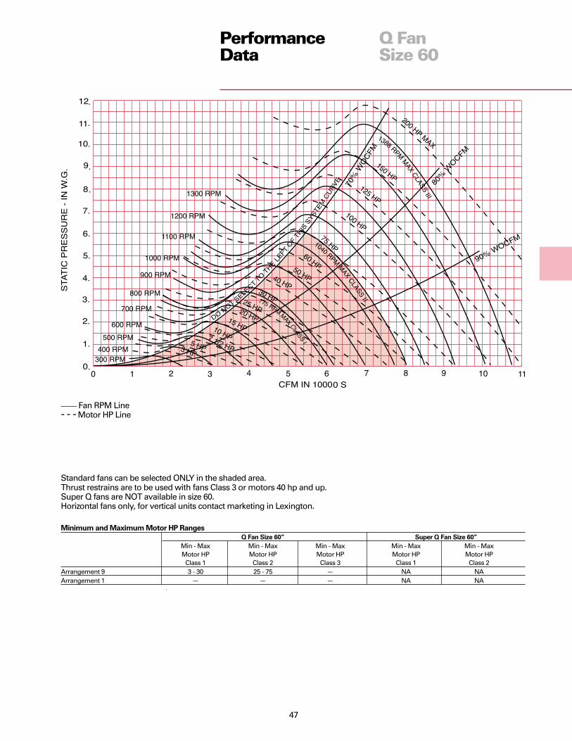
47
PerformanceData
Q FanSize 60
Standard fans can be selected ONLY in the shaded area.Thrust restrains are to be used with fans Class 3 or motors 40 hp and up.Super Q fans are NOT available in size 60.Horizontal fans only, for vertical units contact marketing in Lexington.
Minimum and Maximum Motor HP Ranges
Q Fan Size 60” Super Q Fan Size 60”
Min - Max Min - Max Min - Max Min - Max Min - MaxMotor HP Motor HP Motor HP Motor HP Motor HP
Class 1 Class 2 Class 3 Class 1 Class 2Arrangement 9 3 - 30 25 - 75 — NA NAArrangement 1 — — — NA NA
____ Fan RPM Line- - - Motor HP Line

48
Arrangement 9 Dimensions
Drive UnitIn Out H Shaft Net Wt.
Size A B L W Max. Dia. Lbs.16 Class I 19 3/8 17 7/8 28 3/8 23 5/8 45 15/16 11516 Class II 19 3/8 17 7/8 28 3/8 23 5/8 45 15/16 11516 Class III 19 3/8 17 7/8 28 3/8 23 5/8 45 1 3/16 12019 Class I 21 7/8 20 1/2 28 7/8 26 1/8 48 1/4 15/16 13519 Class II 21 7/8 20 1/2 28 7/8 26 1/8 48 1/4 15/16 13519 Class III 21 7/8 20 1/2 28 7/8 26 1/8 48 1/4 1 3/16 14021 Class I 24 5/8 23 1/8 32 3/4 29 51 3/8 15/16 17521 Class II 24 5/8 23 1/8 32 3/4 29 51 3/8 1 3/16 18021 Class III 24 5/8 23 1/8 32 3/4 29 51 3/8 1 3/16 18524 Class I 28 1/8 26 3/8 35 3/8 32 7/8 55 1/4 1 3/16 21524 Class II 28 1/8 26 3/8 35 3/8 32 7/8 55 1/4 1 3/16 22024 Class III 28 1/8 26 3/8 35 3/8 32 7/8 55 1/4 1 11/16 22527 Class I 30 7/8 29 38 35 3/4 58 1/8 1 3/16 27527 Class II 30 7/8 29 38 35 3/4 58 1/8 1 7/16 29027 Class III 30 7/8 29 38 35 3/4 58 1/8 1 15/16 30530 Class I 34 3/8 32 1/4 41 1/8 39 1/8 61 5/8 1 3/16 35030 Class II 34 3/8 32 1/4 41 1/8 39 1/8 61 5/8 1 7/16 36030 Class III 34 3/8 32 1/4 41 1/8 39 1/8 61 5/8 1 15/16 37533 Class I 37 3/4 35 1/2 45 42 5/8 65 1/8 1 3/16 44033 Class II 37 3/4 35 1/2 45 42 5/8 65 1/8 1 7/16 45033 Class III 37 3/4 35 1/2 45 42 5/8 65 1/8 2 3/16 48536 Class I 41 3/4 39 1/4 49 1/2 47 5/8 69 5/8 1 7/16 57536 Class II 41 3/4 39 1/4 49 1/2 47 5/8 69 5/8 1 11/16 58036 Class III 41 3/4 39 1/4 49 1/2 47 5/8 69 5/8 2 7/16 63040 Class I 46 43 1/4 53 3/4 51 7/8 77 1 7/16 71040 Class II 46 43 1/4 53 3/4 51 7/8 77 1 11/16 72040 Class III 46 43 1/4 53 3/4 51 7/8 77 2 15/16 80044 Class I 50 7/8 47 3/4 60 5/8 56 3/4 82 1 11/16 83044 Class II 50 7/8 47 3/4 60 5/8 56 3/4 82 1 15/16 85044 Class III 50 7/8 47 3/4 60 5/8 56 3/4 82 3 7/16 950
Approximate weights are without motor and drive.
Motor position should be determined from the outlet side.
DimensionalData andWeights
Roughing-In Dimensions
Arrangement 9
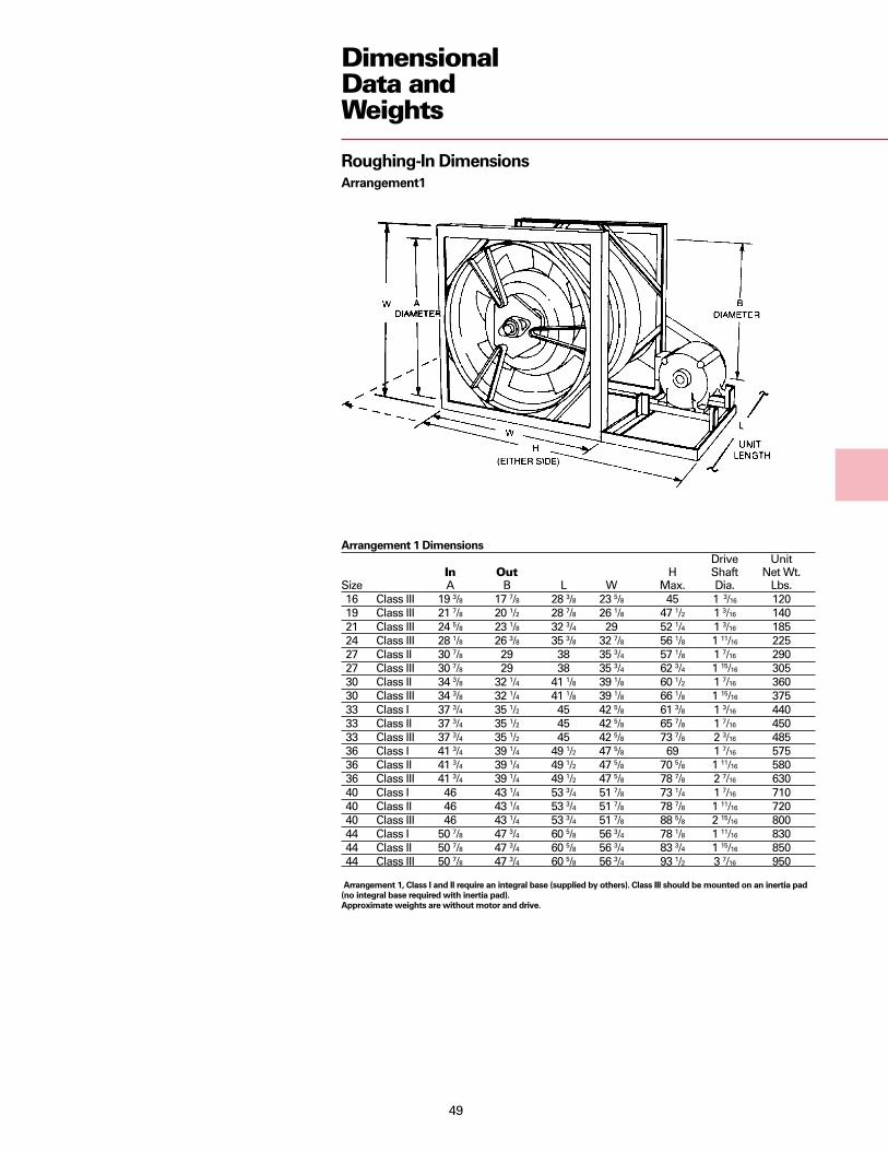
49
Arrangement 1 Dimensions
Drive UnitIn Out H Shaft Net Wt.
Size A B L W Max. Dia. Lbs.16 Class III 19 3/8 17 7/8 28 3/8 23 5/8 45 1 3/16 12019 Class III 21 7/8 20 1/2 28 7/8 26 1/8 47 1/2 1 3/16 14021 Class III 24 5/8 23 1/8 32 3/4 29 52 1/4 1 3/16 18524 Class III 28 1/8 26 3/8 35 3/8 32 7/8 56 1/8 1 11/16 22527 Class II 30 7/8 29 38 35 3/4 57 1/8 1 7/16 29027 Class III 30 7/8 29 38 35 3/4 62 3/4 1 15/16 30530 Class II 34 3/8 32 1/4 41 1/8 39 1/8 60 1/2 1 7/16 36030 Class III 34 3/8 32 1/4 41 1/8 39 1/8 66 1/8 1 15/16 37533 Class I 37 3/4 35 1/2 45 42 5/8 61 3/8 1 3/16 44033 Class II 37 3/4 35 1/2 45 42 5/8 65 7/8 1 7/16 45033 Class III 37 3/4 35 1/2 45 42 5/8 73 7/8 2 3/16 48536 Class I 41 3/4 39 1/4 49 1/2 47 5/8 69 1 7/16 57536 Class II 41 3/4 39 1/4 49 1/2 47 5/8 70 5/8 1 11/16 58036 Class III 41 3/4 39 1/4 49 1/2 47 5/8 78 7/8 2 7/16 63040 Class I 46 43 1/4 53 3/4 51 7/8 73 1/4 1 7/16 71040 Class II 46 43 1/4 53 3/4 51 7/8 78 7/8 1 11/16 72040 Class III 46 43 1/4 53 3/4 51 7/8 88 5/8 2 15/16 80044 Class I 50 7/8 47 3/4 60 5/8 56 3/4 78 1/8 1 11/16 83044 Class II 50 7/8 47 3/4 60 5/8 56 3/4 83 3/4 1 15/16 85044 Class III 50 7/8 47 3/4 60 5/8 56 3/4 93 1/2 3 7/16 950
Arrangement 1, Class I and II require an integral base (supplied by others). Class III should be mounted on an inertia pad
(no integral base required with inertia pad).
Approximate weights are without motor and drive.
Roughing-In Dimensions
Arrangement1
DimensionalData andWeights

50
DimensionalData andWeights
Roughing-In Dimensions
Arrangement 9
Arrangement 9 Dimensions
Drive UnitH Shaft Net Wt.
Size A L W Max. Dia. Lbs.49 Class I 52 3/8 76 57 1/8 79 7/8 1 11/16 102049 Class II 52 3/8 76 57 1/8 85 1/2 2 3/16 107554 Class I 58 81 7/8 62 3/4 85 1/2 1 15/16 109054 Class II 58 81 7/8 62 3/4 91 1/4 2 7/16 114060 Class I 64 1/8 92 69 3/4 96 1/4 2 3/16 173060 Class II 64 1/8 92 69 3/4 108 1/4 2 11/16 1830
Approximate weights are without motor and drive.

51
DimensionalData andWeights
Table D-2 — Outlet Diffuser (Equalizer) DimensionsFan Size A B C D E
16 17 7/8 19 1/4 3 1 1/8 5 1/819 20 1/2 21 5/8 3 1/2 1 5 1/221 23 1/4 24 1/2 4 1 1/4 6 1/824 26 3/8 27 7/8 4 1/2 1 1/8 6 5/827 29 1/8 30 3/4 5 1 1/8 730 32 1/4 34 1/4 5 1/2 1 1/4 7 3/433 35 1/2 37 5/8 6 1 1/4 8 1/436 39 1/4 41 5/8 6 5/8 1 1/4 8 7/840 43 1/4 45 7/8 7 3/8 1 1/8 9 3/844 47 3/4 50 3/4 8 1/8 1 1/4 10 3/8
Figure D-2 — Q Fan Duct Outlet Diffuser, Sizes 16-44
Figure D-1 — Q Fan Inlet Vanes
Table D-1 — Inlet Vane DimensionsNumber Approx.
Fan Size A C of blades Wt. Lbs.16 19.562 11.625 9 8519 22.062 12.500 11 11021 24.875 12.375 11 12024 28.312 12.000 11 14027 31.125 12.375 11 15030 34.562 12.375 11 17533 38.000 12.813 15 18536 42.062 14.250 15 24540 46.312 17.250 15 30044 51.188 18.438 17 35349 52.562 18.188 17 39154 58.250 19.000 17 47860 64.250 20.750 17 558
Q FanAccessoryDimensions
A
½”
B
1” C D
E

52
Q FanAccessoryDimensions
DimensionalData andWeights
Figure D-3 — Super Q II 16-44 Sizes
Table D-3Unit Inlet Area Outlet Area UnitSize A B C D E Sq. Ft. F Sq. Ft. G H L W Weights*16 11 7/8 15 1/4 45 3/8 28 20 1/8 2.2 17 7/8 1.8 24 30 39 1/2 44 1/4 41119 13 1/8 16 1/2 45 7/8 30 1/2 22 1/8 2.6 19 7/8 2.2 26 32 1/2 40 46 7/8 45121 14 1/2 17 7/8 49 3/4 33 3/8 26 1/8 3.7 22 7/8 2.9 30 35 3/8 43 7/8 50 53724 16 1/2 19 3/4 52 3/8 37 1/4 28 1/8 4.3 25 7/8 3.7 32 39 1/4 46 3/8 55 63427 17 7/8 21 1/4 55 40 1/8 32 1/8 5.6 28 7/8 4.6 36 42 1/8 49 1/8 57 7/8 74230 19 7/8 23 58 1/8 43 3/4 34 1/8 6.3 31 7/8 5.6 38 45 3/4 52 1/4 63 1/2 88133 21 3/8 24 5/8 61 7/8 47 1/8 38 1/8 7.9 35 7/8 7.0 42 49 1/8 56 70 1/2 104836 24 1/8 27 1/8 66 1/2 53 42 1/8 9.2 39 7/8 8.7 46 55 60 5/8 75 1/4 137540 26 1/4 29 1/4 70 3/4 56 1/2 46 1/8 11.6 43 7/8 10.6 50 58 1/2 64 7/8 81 7/8 156744 28 7/8 31 3/4 77 5/8 62 1/4 52 1/8 14.9 47 7/8 12.6 56 64 1/4 71 3/4 86 3/4 1858
* Approximate weights are without motor and drive.

53
Q FanAccessoryDimensions
DimensionalData andWeights
Table D-7 — Long Inlet Plus SilencerFan Approx.Size D B L Weight16” 20” 28” 40” 9719” 22” 30” 44” 11721” 26” 34” 52” 17024” 28” 36” 56” 19627” 32” 40” 64” 25630” 34” 42” 68” 29633” 38” 46” 76” 37036” 42” 50” 84” 45540” 46” 54” 92” 634
44” 52” 60” 104” 755 49” 52” 60” 104” 888 54” 58” 66” 116” 1359 60” 64” 72” 128” 1704
Note: Silencer center body is fixed in position.
Table D-6 — Short Inlet Plus SilencerFan Approx.Size D B L Weight16” 20” 28” 20” 4919” 22” 30” 22” 5921” 26” 34” 26” 8524” 28” 36” 28” 9827” 32” 40” 32” 12830” 34” 42” 34” 14833” 38” 46” 38” 18536” 42” 50” 42” 22840” 46” 54” 46” 31744” 52” 60” 52” 37849” 52” 60” 52” 44454” 58” 66” 58” 68060” 64” 72” 64” 852
Note: Silencer center body is fixed in position.
Table D-4 — Short Outlet Plus SilencerFan Approx.Size D B L Weight16” 18” 26” 18” 6819” 20” 28” 20” 8221” 23” 31” 23” 10224” 26” 34” 26” 13027” 29” 37” 29” 16630” 32” 40” 32” 18233” 36” 44” 36” 26036” 40” 48” 40” 31540” 44” 52” 44” 42644” 48” 56” 48” 53449” 52” 60” 52” 65254” 58” 66” 58” 85060” 64” 72” 64” 1050
Note: Silencer center body is adjustable. D dimension is
nominal duct size on entering air end and fitting size on
leaving air end.
Table D-5 — Long Outlet Plus SilencerFan Approx.Size D B L Weight16” 18” 26” 36” 13619” 20” 28” 40” 16421” 23” 31” 46” 20424” 26” 34” 52” 26027” 29” 37” 58” 33230” 32” 40” 64” 36433” 36” 44” 72” 52036” 40” 48” 80” 63040” 44” 52” 88” 85244” 48” 56” 96” 106849” 52” 60” 104” 130454” 58” 66” 116” 170060” 64” 72” 128” 2100
Note: Silencer center body is adjustable. Ddimension is nominal duct size on entering air endand fitting size on leaving air end.
fFigure D-4 — Q Fan/Super Q II Plus Outlet Silencers
Figure D-5 — Q Fan/Super Q II Plus Inlet Silencers

54
Q FAN ASSEMBLY
HousingHousings are 14-gauge steelhydraulically expanded to formintegral inlet bell and diffuser sections.Hydraulically expanded stiffening ringwelded in area of wheel raceway. OnVAV variable speed fan units, fan inletsupports are structurally reinforced tohandle extra stresses of variable speedfan modulation and fan is balanced atten different fan speeds over thedesired operating range.
Inlet/Outlet ShellsFan has tapered inlet and outletshells over fan hub assembly. Shellsuniformly accelerate air throughblade area. End bell covers fan driveassembly, thereby reducing flowturbulence. Eight fan blades areprecision aluminum casting with airfoilcross sections. Blade to shell clearanceis in the range of 30 mils.
Fan WheelFans size 16-44 have fan wheel ofprecision aluminum casting with eightradially projected blades with air-foilcross sections.
Fans size 49-60 have fan wheel ofsixteen precision cast and machinedaluminum blades mounted on a steelwheel plate.
All wheels are dynamically balancedand keyed to fan shaft.
DiffuserCast aluminum diffuser with 29 radiallyprojected straightening vanes withairfoil cross sections. Leading edge ofvanes are curved to reduce tone noisegeneration. Clips on almost every othervane eliminate harmonic ring potential.
ShaftSolid AISI-C1040 hot-rolled steel, turnedand polished. Close tolerancesmaintained where shaft makes contactwith bearings.
BearingsPrecision, flange-mounted, self-aligningball bearings at inlet and discharge.Bearings on all sizes are greaselubricated and selected for a minimumaverage life (AFBMA L-50) in excess of200,000 hours at maximum catalogedoperating conditions. Bearinggreaselines are extended out throughfan shell for easy servicing.
MechanicalSpecifications
DrivesMechanical drives are computerselected for low noise, lowmaintenance operation. Centerdistance and arc of contact ismaintained within prefixed limits.Constant speed fans use variable orconstant pitch drives; variable speedmodulated fans use fixed drives only.
SUPER QUIET II FANSTrane Super Quiet II (SQ2) fans includefan housing, wheel, shaft, bearings,diffuser section, motor mountingsupport, ODP standard or highefficiency motor, drives, springisolation in acoustically-treated casingin a factory-assembled unit. Fan motorsare outside of airstream.
Constant volume units (SQ2C) areequipped with variable or constantpitch drives. Variable air volume units(SQ2V) use adjustable frequencyinverters for fan capacity modulationand must have constant pitch drives.Inlet vanes are NOT available forSuper Q II fans.
ENCLOSUREFans are internally isolated on fourheight saving spring isolators andthen flex connected inside of an airtightacoustical enclosure. Walls are16-gauge steel, internally lined withtwo-inch thick three-pound persquare foot density fiberglass. Airsidesurface of acoustical lining is coatedwith black matte faced lining to preventscuffing.
Enclosure has two large full sizeside access panels. Access panels arefully gasketed and mechanicallyattached to casing for easy removal.Enclosure has access panel positioningfeet to insure easy access panelreplacement after removal.
Duct connections in enclosure endpanels slip connect to standard U.S.round duct sizes.
Fan grease lines are extended throughenclosure for easy servicing of fan.Optional fan motor leads are extendedthrough casing for easier installation.
Two rails support the entire enclosure.Rails can be rested on floor or hungfrom the ceiling with steel rods. Ductscan be directly connected to enclosuresince fan is internally isolated.
Enclosure is rated for four-inchnegative or five-inch positive pressure.

55
ACCESSORIES
Inlet Screen (Q, SQ2)Heavy-gauge steel wire mesh.
Inlet Bellmouth (Q, SQ2)On unducted inlets, the radiusbellmouth uniformly accelerates airinto the fan, reducing noise and energyrequirements.
Plus Duct Silencer (Q, SQ2)Significantly attenuates fan airbornesound levels. Center body of roundsilencer is dimensional matched toQ-fan hub. Center body is fieldadjustable in the direction of airflow.This allows hub to be located close toQ-fan, thereby reducing flowgenerated turbulence and noise.Silencers can be on inlet and/or outletand come in short and long lengthversions. Silencers are flex connectedto Q fans and slip connected directly toSuper Q II enclosures. Silencers areshipped loose for field installation.
Inlet Flange (Q)Rolled steel ring, factory-mounted, forflanged duct connection. Sizes 16 to 21one-inch flanges, sizes 27 to 44 are1½-inch flanges.
Adjustable Inlet Vanes11 steel vanes operated by a positiveperipheral control mechanism locatedout of the airstream. Each vane issupported at both ends by a precisionbronze bearing. The control arm issuitable for manual or automaticoperation. Inlet vanes are shippedloose for field installation.
MechanicalSpecifications
Outlet Flange (Q)Rolled steel ring, factory-mounted, forflanged duct connection.
Outlet Diffuser (Equalizer) (Q)Steel spinning with 30 degree includeddiffusion angle. Permit same size slip-duct connection on discharge as inlet.
Outlet Screen (Q)Heavy-gauge steel wire mesh.
Outlet Flow StabilizationScreen (Q, SQ2)Similar to outlet screen, but openingsare much smaller. Designed to act asan airflow stabilization device on theoutlet of each fan.

Since The Trane Company has a policy of continuousproduct improvement, it reserves the right to changedesign and specification without notice.
Library Product Literature
Product Section Air Handling
Product Fans
Model 000
Literature Type Data Sales Catalog
Sequence 2
Date August 2000
File No. PL-AH-FAN-000-DS-2-0800
Supersedes FAN-DS-2 597
Ordering No. FAN-DS-2
The Trane Company
An American Standard Company
www.trane.com
For more information contact yourlocal sales office or e-mail us [email protected]