Fan Coil Control Range - sabiana.co.uk Fly/Fan Coil Control... · for the Carisma and SkyStar...
40
Fan Coil Control Range
Transcript of Fan Coil Control Range - sabiana.co.uk Fly/Fan Coil Control... · for the Carisma and SkyStar...

Fan CoilControl Range
CONT
ROLS
- 0
3/16
COd. A
4CC0
100
A/
03/1
6
Sabiana s.p.a. • via Piave, 53 • 20011 Corbetta • Milano • Italyphone +39.02.97203.1 r.a. / +39.02.97270429 / +39.02.97270576 • fax +39.02.9777282 / +39.02.9772820
www.sabiana.it • [email protected]

for the Carisma and SkyStar Cassette fan coil rangeswith AC asynchronous motor and with EC electronic motor and inverter board
Accessories for BMS systemswhich are not provided by Sabiana
for the Carisma and SkyStar Cassette fan coil rangeswith AC asynchronous motor and with EC electronic motor and inverter board
MB and SABIANETaccessories
39
INDEX• Controls by Sabiana Page 3
• Overview of the controls: - Controls fitted on the unit with AC asynchronous motor Page 4 - Wall controls with AC asynchronous motor Page 6 - Wall controls and fitted on the unit with EC electronic motor Page 8
• Description of the controls: - Controls fitted on the unit with AC asynchronous motor Page 10 - Controls fitted on the unit for fan coils with AC asynchronous motor, Crystall electronic filter or electric heater Page 12 - Controls fitted on the unit with EC electronic motor and inverter board Page 13 - Wall controls with AC asynchronous motor Page 14 - Wall controls unit with EC electronic motor and inverter board Page 17
• Power unit and speed switches Page 18
• Accessories Page 20
• FreeSabiana wireless control system Page 22
• MB controls and units Page 26
• SABIANET management system for a network of fan coils Page 35
• MB and SABIANET accessories Page 39
• Accessories for BMS systems which are not provided by Sabiana Page 39
The descriptions and illustrations provided in this publication are not binding:
Sabiana reserves the right, whilst maintaining the essential characteristics
of the types described and illustrated, to make, at any time,
without the requirement to promptly update this piece of literature,
any changes that it considers useful for the purpose of improvement
or for any other manufacturing or commercial requirements.
For technical details read carefullythe manual of installation, use and maintenance.
To combine with:
To combine with:
CRC
CRC
CRT
CRT
CRR
CRR
CRSO
CRSO
SK-MB
SK-MB
CCN
CCN
CVP-MB
CVP-MB
CRC-ECM
CRC-ECM
CRT-ECM
CRT-ECM
MVI
MVI
CRS-ECM
CRS-ECM
SK-ECM-MB
SK-ECM-MB
CCN-ECM
CCN-ECM
CVP-ECM-MB
CVP-ECM-MB
Router-SThe Router-S is an electronic board that:• allows creating networks with more than 60 units (minimum 2 Router-S are required) or to divide the network (per floor, building, etc.).• it allows creating a Master/Slave sub-network to be controlled as an indipendent group.
The Router-S can be used only inside a network managed by Sabianet.
The number of Router-S to be used is: • up to 60 units: no Router-S. • from 61 to 120 units: 2 Router-S. • every 60 subsequent units: 1 additional Router-S.
Router-BMSThe Router-BMS (ModBus) is an electronic board to use with BMS systems not supplied bySabiana:• it allows to set-up a Master/Slave sub-network to check as an indipendent network.
The number of Router-BMS (ModBus) to use is:• maximum 14 Router-BMS.• maximum 15 fan coils per Router-BMS.
SIOSSIOS is a board equipped with 8 relays with potential free contact to control the activation ordeactivation of remote electric utilities. Moreover, the board has 8 digital inlets to display theactuators or external consents, such as motor or other.
The SIOS boards can be connected:• inside a network managed by Sabianet.• to a PSM-DI panel (one SIOS for each PSM-DI panel).
Router-S
Router-BMS
SIOS
Identification
Identification
Identification
3021290
3021340
3021292
Code
Code
Code

3
Carisma Coanda one way Cassette fan coils CCN range with AC asynchronous motor and centrifugal fanCCN-ECM range with EC electronic motor and centrifugal fan
High pressure Carisma fan coils CRSO range with AC asynchronous motor and centrifugal fanCRS-ECM range with EC electronic motor and centrifugal fan
Carisma MVI fan coils rangewith AC asynchronous motor and centrifugal fan
Carisma fan coilsCRC range with AC asynchronous motor and centrifugal fanCRC-ECM range with EC electronic motor and centrifugal fanCRT range with AC asynchronous motor and tangential fanCRT-ECM range with EC electronic motor and tangential fan
Carisma CRR fan coils rangewith AC asynchronous motor and tangential fan
Carisma Fly fan coilsCVP range with AC asynchronous motorCVP-ECM range with EC electronic motor
SkyStar Cassette fan coilsSK range with AC asynchronous motorSK-ECM range with EC electronic motor
Controls by Sabianato combine with the following fan coil range
with AC asynchronous motor and with EC electronic motor and inverter board

4
Thermostatic control of the water valves (ON-OFF) and the electric heater managed as mainheating element or as an integration element (4 pipe system + electric heater) - NO Crystall
Automatic Summer/Winter switch and continuous chilled and hot water supply,it allows the automatic summer winter change-over in accordance to the room temperature
-1°C = Winter, +1°C = Summer, Neutral Zone 2°C (4 pipe installations with 2 valve)
Thermostatic control of the chilled water valve (ON-OFF) and the electric heater (BEL)
Summer/winter cycle with a centralized and remote switchor with an automatic change-over fitted on the water pipe (for 2 pipe system)
Manual Summer/Winter switch
Simultaneous thermostatic control of the valve and fan
Electronic room thermostat for two water valve control (4 pipe system)
Electronic room thermostat for one water valve control (2 pipe system)
Electronic room thermostat for fan control (ON-OFF)
Automatic 3 speed progressive push button
Manual 3 speed switch
Electric heater/IAQ filter activation button
ON-OFF switch
Manual 3 speed switch without thermostatic control
Possibility to use a low temperature cut-out thermostat (optional)
Installation manual codes
☞See page
Fan coil
with AC asynchronous motorcontrols fitted on the unit
The Fan coil controls fitted on the unit are only suitable for Sabiana units.Standard reference: EN 60335-2-40.
Carisma CRR
Carisma CRC / CRT
To combine with:

510 10 11 11 12 12 12
4050875 4050876 4050877 4050857 4050880 4050881 4050898
CB-AUT-IAQ
9066322
CB-R-IAQ
9066306
CB-IAQ
9066305
CB-AUT
9066318
CB-C
9066302
CB-T
9066301
CB
9066300
Code
Identification

6
Thermostatic control of the water valves (ON-OFF) and the electric heater managed as mainheating element or as an integration element (4 pipe system + electric heater) - NO Crystall
Automatic Summer/Winter switch and continuous chilled and hot water supply,it allows the automatic summer winter change-over in accordance to the room temperature
-1°C = Winter, +1°C = Summer, Neutral Zone 2°C (4 pipe installations with 2 valve)
Thermostatic control of the chilled water valve (ON-OFF) and the electric heater (BEL)
Summer/winter cycle with a centralized and remote switchor with an automatic change-over fitted on the water pipe (for 2 pipe system)
Manual Summer/Winter switch
Simultaneous thermostatic control of the valve and fan
Electronic room thermostat for two water valve control (4 pipe system)
Electronic room thermostat for one water valve control (2 pipe system)
Electronic room thermostat for fan control (ON-OFF)
Automatic 3 speed progressive push button
Manual 3 speed switch
Electric heater/IAQ filter activation button
ON-OFF switch
Manual 3 speed switch without thermostatic control
Possibility to use a low temperature cut-out thermostat (optional)
Energy saving function
Button lock controller
Installation manual codes
☞See page
Carisma Fly CVP
Cassette SkyStar SKCarisma CCN one way CassetteCarisma CRC / CRT / CRSO / MVI
To combine with:
Fan coil
with AC asynchronous motorwall controls
The wall controls arein compliance with the standard reference CEI EN 60730.

7
4050963A/B− 4050961 4050962 4050963A/B 079303 −14 14 15 15 15 16 16
90661749066173
9066331E9066632
90666319066630
9066642
T2TTMO-503-SV2T-MBWM-AUWM-TQRWM-TWM-3V
Code
Identification

8
Thermostatic control of the water valves (ON-OFF) and the electric heater managed as mainheating element or as an integration element (4 pipe system + electric heater) - NO Crystall
Automatic Summer/Winter switch and continuous chilled and hot water supply,it allows the automatic summer winter change-over in accordance to the room temperature
-1°C = Winter, +1°C = Summer, Neutral Zone 2°C (4 pipe installations with 2 valve)
Thermostatic control of the chilled water valve (ON-OFF) and the electric heater (BEL)
Summer/winter cycle with a centralized and remote switchor with an automatic change-over fitted on the water pipe (for 2 pipe system)
Manual Summer/Winter switch
Simultaneous thermostatic control of the valve and fan
Electronic room thermostat for two water valve control (4 pipe system)
Electronic room thermostat for one water valve control (2 pipe system)
Electronic room thermostat for fan control (ON-OFF)
Automatic 3 speed progressive push button
Automatic continuous speed control
Manual 3 speed switch
Electric heater/IAQ filter activation button
ON-OFF switch
Possibility to use a low temperature cut-out thermostat (optional)
Energy saving function
Button lock controller
Installation manual codes
☞See page
Cassette SkyStar SK-ECMCarisma CCN-ECM one way CassetteCarisma CRS-ECM
Carisma CRC-ECM / CRT-ECM
To combine with:
Fan coil
and inverter boardcontrols with EC electronic motor
The Fan coil controls fitted on the unit are only suitable for Sabiana units.Standard reference: EN 60335-2-40.
The wall controls arein compliance with the standard reference CEI EN 60730.

9
4050882 −4050963A/B4050963A/B4050855
13 17171713
90666449066331E90666329066320 9066308
WALLFITTED
WM-S-ECMT-MBWM-AUCB-T-ECM CB-T-ECM-IAQ
Code
Identification

10
To combine with:
To combine with:
CRC
CRC
CRT
CRT
CRR
CRR
CRSO
CRSO
SK
SK
CCN
CCN
CVP
CVP
MVI
MVI
• Manual 3 speed switch, without thermostatic control.• It allows to control the low temperature cut-out thermostat (TMM).
• Manual 3 speed switch.• Manual Summer/Winter switch.• Electronic room thermostat for fan control (ON-OFF).• Electronic room thermostat for valve control (ON-OFF) (the fan keeps working).• It allows to control the low temperature cut-out thermostat (TMM).• It allows to control the chilled water valve (ON-OFF) and the electric heater (BEL).• Presence of a LED signal when the thermostat is on.
Control power absorption: 1,5 VA
CB
CB-T
Identification
Identification
9066300
9066301
Code
Code
Controls fitted on the unit
for fan coilswith AC asynchronous motor
For Carisma MV and MVB ranges the room temperaturecan be controlled with electronic room thermostats fitted on the unit
with different solutions according to every ambient conditions;the control range includes manual or automatic speed switch control,
thermostatic control of the water valves or of the electric heater,manual, automatic or centralized summer/winter switch.
With the suitable speed switchesit is also possible to control with the same thermostat up to 8 units.
Here below there is the description of all controls for the AC asynchronous motorversions and for the versions with EC electronic motor and inverter board.

11
To combine with: CRC CRT CRR CRSO SK CCN CVP MVI
To combine with: CRC CRT CRR CRSO SK CCN CVP MVI
• Manual 3 speed switch.• Manual, automatic or centralized Summer/Winter switch.• Electronic room thermostat for fan control (ON-OFF).• Electronic room thermostat for valve control (ON-OFF) (the fan keeps working).• It allows to control the low temperature cut-out thermostat (TME).• It allows to control the chilled water valve (ON-OFF) and the electric heater (BEL).• Presence of a LED signal when the thermostat is on.
Control power absorption: 1,5 VA
• Manual/automatic 3 speed switch.• Manual, automatic or centralized Summer/Winter switch.• Automatic speed switch: on Auto Mode there is the automatic speed selection in accordance to the difference between room temperature and setpoint. When the setpoint is reached the fan goes on OFF.• Electronic room thermostat for valve control (ON-OFF) (the fan keeps working).• Simultaneous thermostatic control of the valves and fan.• It allows to control the low temperature cut-out thermostat (NTC).• It allows to control the chilled water valve (ON-OFF) and the electric heater (BEL).• It allows to control the summer/winter cycle with a centralized and remote switch or with an automatic change-over fitted on the water pipe (for 2-tube installations only).• Presence of a LED signal when the thermostat is on.
N.B.: with 4 pipe installations and continuous chilled and hot water supply, it allows the automatic summer winter change- over in accordance to the room temperature (-1°C = Winter, +1°C = Summer, Neutral Zone 2°C).
Control power absorption: 1,5 VA
CB-C
CB-AUT
Identification
Identification
9066302
9066318
Code
Code
Controls fitted on the unitfor fan coils
with AC asynchronous motor

12
To combine with: CRC CRT CRR CRSO SK CCN CVP MVI
To combine with: CRC CRT CRR CRSO SK CCN CVP MVI
To combine with: CRC CRT CRR CRSO SK CCN CVP MVI
• Manual 3 speed switch.• IAQ filter activation button.• Without thermostatic control.• It allows to control the low temperature cut-out thermostat (TMM).
• Manual 3 speed switch.• Manual, automatic or centralized Summer/Winter switch.• Electric heater/IAQ filter activation button.• Electronic room thermostat for fan control (ON-OFF).• Electronic room thermostat for valve control (ON-OFF) (the fan keeps working).• It allows to control the low temperature cut-out thermostat (TME).• It allows to control the chilled water valve (ON-OFF) and the electric heater (BEL).• Presence of a LED signal when the thermostat is on.
Control power absorption: 1,5 VA
• Manual/automatic 3 speed switch.• Manual, automatic or centralized Summer/Winter switch.• Electric heater/IAQ filter activation button.• Automatic speed switch: on Auto Mode there is the automatic speed selection in accordance to the difference between room temperature and setpoint. When the setpoint is reached the fan goes on OFF.• Electronic room thermostat for valve control (ON-OFF) (the fan keeps working).• It allows to control the low temperature cut-out thermostat (NTC).• It allows to control the water valves (ON-OFF) and the electric heater managed as main heating element or as an integration element.• Presence of a LED signal when the thermostat is on.
N.B.: with 4 pipe installations and continuous chilled and hot water supply, it allows the automatic summer winter change- over in accordance to the room temperature (-1°C = Winter, +1°C = Summer, Neutral Zone 2°C).
Control power absorption: 1,5 VA
CB-IAQ
CB-R-IAQ
CB-AUT-IAQ
Identification
Identification
Identification
9066305
9066306
9066322
Code
Code
Code
Controls fitted on the unitfor fan coils
with AC asynchronous motor, Crystall electronic filter or electric heater

13
To combine with: CRC-ECM CRT-ECM CRS-ECM SK-ECM CCN-ECM CVP-ECM
To combine with: CRC-ECM CRT-ECM CRS-ECM SK-ECM CCN-ECM CVP-ECM
• Manual 3 speed switch or automatic continuous speed control.• Manual Summer/Winter switch.• Continuous speed control based on the difference between ambient temperature and Set temperature (speed switch in Auto position).• Electronic room thermostat for fan and water valve control (ON-OFF).• Simultaneous thermostatic control of the valves and fan.• It allows to control the temperature cut-out (NTC).• Presence of a LED signal when the thermostat is on.
Control power absorption: 1,5 VA
• Manual 3 speed switch or automatic continuous speed control.• Manual, automatic or centralized Summer/Winter switch.• Continuous speed control based on the difference between ambient temperature and Set temperature (speed switch in Auto position).• Electric heater/IAQ filter activation button.• Automatic speed switch: on Auto Mode there is the automatic speed selection in accordance to the difference between room temperature and setpoint. When the setpoint is reached the fan goes on OFF.• Electronic room thermostat for fan control (ON-OFF).• Electronic room thermostat for valve control (ON-OFF) (the fan keeps working).• Simultaneous thermostatic control of the valves and fan.• It allows to control the temperature cut-out (NTC).• Presence of a LED signal when the thermostat is on.
Control power absorption: 1,5 VA
CB-T-ECM
CB-T-ECM-IAQ
Identification
Identification
9066320
9066308
Code
Code
Controls fitted on the unitfor fan coils
with EC electronic motor and inverter board

14
To combine with:
To combine with:
CRC
CRC
CRT
CRT
CRR
CRR
CRSO
CRSO
SK
SK
CCN
CCN
CVP
CVP
MVI
MVI
Dimensions: 75x75x30 mm
Dimensions: 135x86x31 mm
• Manual 3 speed switch.• Without thermostatic control.
• ON-OFF switch.• Manual 3 speed switch.• Manual Summer/Winter switch.• Electronic room thermostat for fan control (ON-OFF).• Electronic room thermostat for valve control (ON-OFF) (the fan keeps working).• It allows to control the low temperature cut-out thermostat (TMM).• It allows to control the chilled water valve (ON-OFF) and the electric heater (BEL) only in case that hot water is not used in winter (otherwise please use WM-TQR control with on/off switch for the electric heater).• Presence of a LED signal when the thermostat is on.
Control power absorption: 0,25 VA
WM-3V
WM-T
Identification
Identification
9066642
9066630
Code
Code
Wall controls
for fan coilswith AC asynchronous motor
For the Carisma and SkyStar range the ambient temperaturecan be controlled through the use of electronic room thermostats mounted on the wall
with different solutions according to every environmental conditions;the control range includes indeed the manual or automatic speed switch control,
the thermostatic control of the water valves or of the electric heater,the manual, automatic or centralized summer/winter switch.
With the suitable speed switchesit is also possible to control with the same thermostat until 8 units.
Here below there is the description of all controls for the AC asynchronous motorversions and for the versions with EC electronic motor and inverter board.

15
To combine with:
To combine with:
To combine with:
CRC
CRC
CRC
CRT
CRT
CRT
CRR
CRR
CRR
CRSO
CRSO
CRSO
SK
SK
SK
CCN
CCN
CCN
CVP
CVP
CVP
MVI
MVI
MVI
Dimensions: 135x86x31 mm
Dimensions: 135x86x24 mm
Dimensions: 110x72x25 mm
• ON-OFF switch.• Manual 3 speed switch.• Manual, automatic or centralized Summer/Winter switch.• Electric heater/IAQ filter activation button.• Electronic room thermostat for fan control (ON-OFF).• Electronic room thermostat for valve control (ON-OFF).• Simultaneus thermostatic control of the valves and fan.• It allows to control the low temperature cut-out thermostat (NTC).• It allows to control the water valves (ON-OFF) and the electric heater managed as main heating element or as an integration element.• Energy saving function.• Presence of a LED signal when the thermostat is on.
Control power absorption: 1 VA
The control must always be connectedwith UPM-AU power unit (fitted on the unit) or with UP-AU power unit (with separate packaging).
• ON-OFF push button.• Manual or automatic 3 speed progressive push button.• Manual, automatic or centralized Summer/Winter switch.• Summer/Winter/Fan/Auto mode push button.• Electric heater/IAQ filter activation button.• Electronic room thermostat for fan and water valves control (ON-OFF).• Simultaneus thermostatic control of the valves and fan.• It allows to use the low temperature cut-out thermostat (NTC) mounted on the UP-AU power unit.• It allows to control the water valves (ON-OFF) and the electric heater managed as main heating element or as an integration element.• Energy saving push button.• Presence of a LED signal when the thermostat is on.
N.B.: with 4 pipe installations and continuous chilled and hot water supply, it allows the automatic summer winter change- over in accordance to the room temperature (-1°C = Winter, +1°C = Summer, Neutral Zone 2°C).
Control power absorption: see the UP-AU power unit
The control must always be connectedwith UPM-AU power unit (fitted on the unit) or with UP-AU power unit (with separate packaging).
Wall control with display that allows controlling one or more units in Master/Slave mode. The control isequipped with internal sensor to detect the room temperature, which can be defined as a priority comparedto the return air sensor on the fan coil.
The T-MB control features the following functions:• Switch the unit ON and OFF.• Temperature set.• Manual, automatic or centralized Summer/Winter switch.• Set the fan speed (low, medium, high or auto fan).• Set the operation mode (fan only, cooling, heating; auto for 4 pipe systems with mode selection depending on the air temperature).• Possibility of use of the low temperature cut-out thermostat NTC mounted on the UP-AU power unit.• It allows to control the water valves (ON-OFF) and the electric heater managed as main heating element or as an integration element.• Time setting.• Weekly ON/OFF program.
Control power absorption: see the UP-AU power unit
WM-TQR
WM-AU
T-MB
Identification
Identification
Identification
9066631
9066632
9066331E
Code
Code
Code
Wall controlsfor fan coils
with AC asynchronous motor

16
To combine with:
To combine with:
CRC
CRC
CRT
CRT
CRR
CRR
CRSO
CRSO
SK
SK
CCN
CCN
CVP
CVP
MVI
MVI
Dimensions: 118x87x8 mm
Dimensions: 128x75x25 mm
The TMO-503-SV2 control for fan coils with valves, is designed to be installed in a 503 wall box.It is easy to use, it has a big and clear display, and a great precision. The control is supplied integralwith the external frame, but it is possible to use frames of the most known brand on the market (BTicino,Vimar, AVE, Gewiss).
• Manual or automatic 3 speed switch.• Manual Summer/Winter switch.• Electronic thermostat for valves control (ON-OFF).• Simultaneus thermostatic control of the valves and fan.• It allows to control the low temperature cut-out thermostat, included with the control.
N.B.: with 4 pipe installations and continuous chilled and hot water supply, it allows the automatic summer/winter change- over in accordance to the room temperature (-1°C = Winter, +1°C = Summer, Neutral Zone 2°C).
N.B.: only for Carisma CRSO version: on size 4 the SEL-CR switch must be installed.
Control power absorption: 1,5 VA
Only for 2 pipe units only.
• ON-OFF switch.• Manual 3 speed switch.• Manual Summer/Winter switch.• Thermostatic control on the fan.• Thermostatic control on the valve and continuous fan operation.• Simultaneous thermostatic control of the valve and fan.
Control power absorption: 1,5 VA
TMO-503-SV2
T2T
Identification
Identification
9060173
9060174
Code
Code
Wall controlsfor fan coils
with AC asynchronous motor

17
To combine with: CRC-ECM CRT-ECM CRS-ECM SK-ECM CCN-ECM CVP-ECM
To combine with: CRC-ECM CRT-ECM CRS-ECM SK-ECM CCN-ECM CVP-ECM
To combine with: CRC-ECM CRT-ECM CRS-ECM SK-ECM CCN-ECM CVP-ECM
Dimensions: 135x86x24 mm
Dimensions: 132x87x23,6 mm
Dimensions: 110x72x25 mm
The control must always be connectedwith UPM-AU power unit (fitted on the unit) or with UP-AU power unit (with separate packaging).
• ON-OFF push button.• Manual or automatic 3 speed progressive push button.• Manual, automatic or centralized Summer/Winter switch.• Summer/Winter/Fan/Auto mode push button.• Electric heater/IAQ filter activation button.• Electronic room thermostat for fan and water valves control (ON-OFF).• Simultaneus thermostatic control of the valves and fan.• It allows to use the low temperature cut-out thermostat (NTC) mounted on the UP-AU power unit.• It allows to control the water valves (ON-OFF) and the electric heater managed as main heating element or as an integration element.• Energy saving push button.• Presence of a LED signal when the thermostat is on.
N.B.: with 4 pipe installations and continuous chilled and hot water supply, it allows the automatic summer winter change- over in accordance to the room temperature (-1°C = Winter, +1°C = Summer, Neutral Zone 2°C).
Control power absorption: see the UP-AU power unit
0-10V control with display designed to be mounted on the wall or to be installed on a 503 wall box.
• ON-OFF switch.• Manual 3 speed switch or automatic continuous speed control.• Manual Summer/Winter switch.• Summer/Winter/Fan/Auto mode push button.• Electronic room thermostat for fan control (ON-OFF).• Electronic room thermostat for valve control (ON-OFF).• Simultaneus thermostatic control of the valves and fan.• It allows to control the low temperature cut-out thermostat (NTC).
Control power absorption: 1,2 VA
The control must always be connectedwith UPM-AU power unit (fitted on the unit) or with UP-AU power unit (with separate packaging).
Wall control with display that allows controlling one or more units in Master/Slave mode. The control isequipped with internal sensor to detect the room temperature, which can be defined as a priority comparedto the return air sensor on the fan coil.
The T-MB control features the following functions:• Switch the unit ON and OFF.• Temperature set.• Manual, automatic or centralized Summer/Winter switch.• Set the fan speed (low, medium, high or auto fan).• Set the operation mode (fan only, cooling, heating; auto for 4 pipe systems with mode selection depending on the air temperature).• It allows to use the low temperature cut-out thermostat (NTC) mounted on the UP-AU power unit.• It allows to control the water valves (ON-OFF) and the electric heater managed as main heating element or as an integration element.• Time setting.• Weekly ON/OFF program.
Control power absorption: see the UP-AU power unit
WM-AU
WM-S-ECM
T-MB
Identification
Identification
Identification
9066632
9066644
9066331E
Code
Code
Code
Wall controlsfor fan coils
with EC electronic motor and inverter board
18
For Fan Coils CRC/CRT, MO-IV-IO versions.
• Speed switch (Slave).• It allows to control up to 8 units with only one centralized wall control (1 speed switch for each unit).
SEL-CR
Identification
9066311
Code
To combine with:CRC CRT CRR CRSO SK CCN CVP
CRC-ECM CRT-ECM MVI CRS-ECM SK-ECM CCN-ECM CVP-ECM
for WM-T, WM-TQR and TMO-503-SV2 controls
For Fan Coils CRC/CRT/CRR, MV-MVB versions.
• Speed switch (Slave).• It allows to control up to 8 units with only one centralized wall control (1 speed switch for each unit).
To combine with:CRC CRT CRR CRSO SK CCN CVP
CRC-ECM CRT-ECM MVI CRS-ECM SK-ECM CCN-ECM CVP-ECM
SEL-CB
Identification
9066304
Code for WM-T, WM-TQR and TMO-503-SV2 controls
for fan coilswith AC asynchronous motor and with EC electronic motor and inverter board
Power unit and speed switchesfor controls
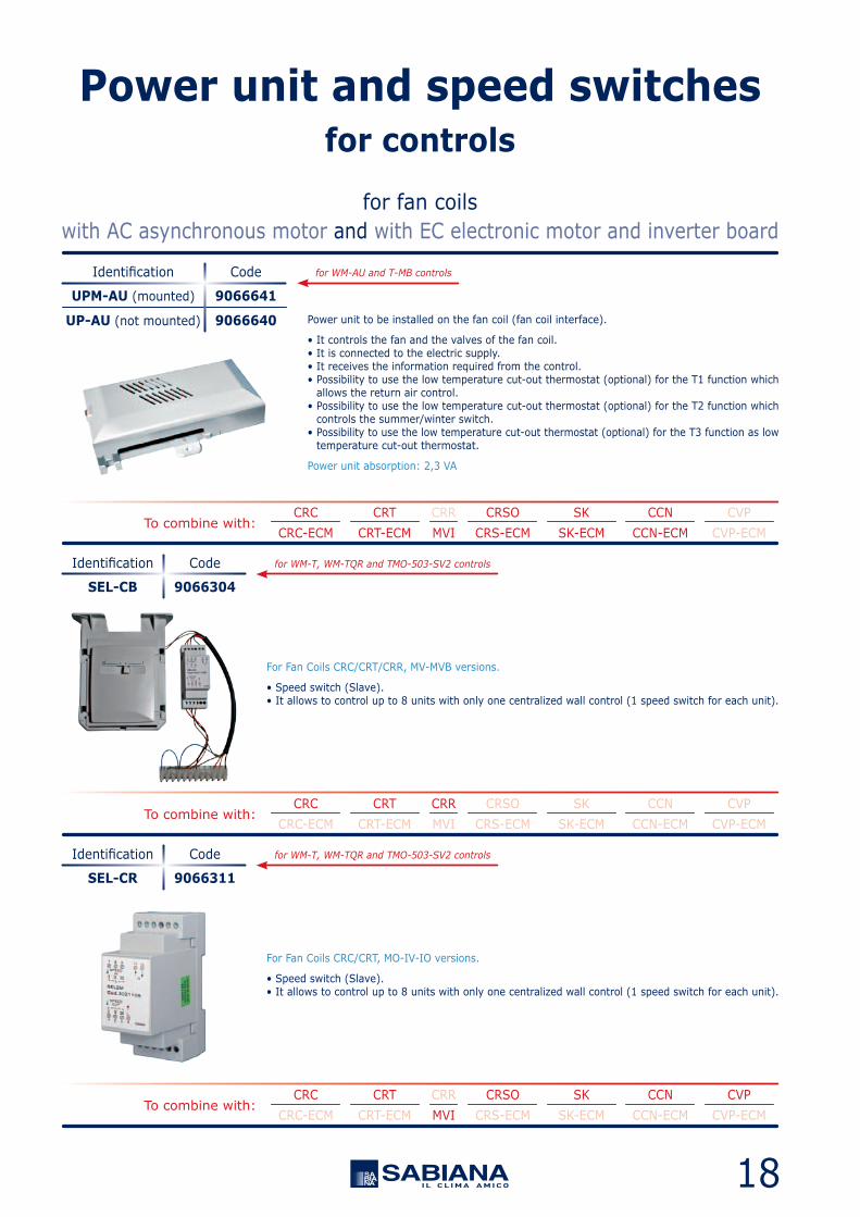
Power unit to be installed on the fan coil (fan coil interface).
• It controls the fan and the valves of the fan coil.• It is connected to the electric supply.• It receives the information required from the control.• Possibility to use the low temperature cut-out thermostat (optional) for the T1 function which allows the return air control.• Possibility to use the low temperature cut-out thermostat (optional) for the T2 function which controls the summer/winter switch.• Possibility to use the low temperature cut-out thermostat (optional) for the T3 function as low temperature cut-out thermostat.
Power unit absorption: 2,3 VA
UPM-AU (mounted)
UP-AU (not mounted)
Identification
9066641
9066640
Code for WM-AU and T-MB controls
To combine with:CRC CRT CRR CRSO SK CCN CVP
CRC-ECM CRT-ECM MVI CRS-ECM SK-ECM CCN-ECM CVP-ECM

19
For Fan Coils CVP version.
• Speed switch (Slave).• It allows to control up to 8 units with only one centralized wall control (1 speed switch for each unit).
SEL-CVP
Identification
9025302
Code
To combine with:CRC CRT CRR CRSO SK CCN CVP
CRC-ECM CRT-ECM MVI CRS-ECM SK-ECM CCN-ECM CVP-ECM
for WM-T, WM-TQR and TMO-503-SV2 controls
For Fan Coils Coanda CCN and SkyStar SK versions.
• Speed switch (Slave).• It allows to control up to 8 units with only one centralized wall control (1 speed switch for each unit).
SEL2M
Identification
9079109
Code
To combine with:CRC CRT CRR CRSO SK CCN CVP
CRC-ECM CRT-ECM MVI CRS-ECM SK-ECM CCN-ECM CVP-ECM
for WM-T, WM-TQR and TMO-503-SV2 controls
for fan coilswith AC asynchronous motor and with EC electronic motor and inverter board
Power unit and speed switchesfor controls

20
To combine with:CRC CRT CRR CRSO SK CCN CVP
CRC-ECM CRT-ECM MVI CRS-ECM SK-ECM CCN-ECM CVP-ECM
To combine with:CRC CRT CRR CRSO SK CCN CVP
CRC-ECM CRT-ECM MVI CRS-ECM SK-ECM CCN-ECM CVP-ECM
Low temperature cut-out thermostat
• To be fitted between the coil fins.• When connecting the control, the TME probe cable must be separated from the power supply wires.• It stops the fan when the water temperature is lower than 38°C and it starts the fan when is higher than 42°C.
Low temperature cut-out thermostat
• To be installed in contact with the hot water circuit.• For units working on heating only.• It stops the fan when the water temperature is lower than 30°C and it starts the fan when is higher than 38°C.
TME
TMM
Identification
Identification
3021091
9053048
Code
Code
for CB-C and CB-R-IAQ controls
for CB, CB-T, CB-IAQ and WM-T controls
for fan coilswith AC asynchronous motor and with EC electronic motor and inverter board
To combine with:CRC CRT CRR CRSO SK CCN CVP
CRC-ECM CRT-ECM MVI CRS-ECM SK-ECM CCN-ECM CVP-ECM
Low temperature cut-out thermostat
• To be fitted between the coil fins.• When connecting the control, the NTC probe cable must be separated from the power supply wires.• It stops the fan when the water temperature is lower than 28°C and it starts the fan when is higher than 33°C.
To use as:• T1 function for the return air control.• T2 function which controls the summer/winter switch.• T3 function as low temperature cut-out thermostat.
NTC
Identification
3021090
Code for CB-AUT, CB-AUT-IAQ, WM-TQR controls and the UP-AU power unit
Accessoriesfor controls

21
for fan coilswith AC asynchronous motor and with EC electronic motor and inverter board
To combine with:CRC CRT CRR CRSO SK CCN CVP
CRC-ECM CRT-ECM MVI CRS-ECM SK-ECM CCN-ECM CVP-ECM
To combine with:CRC CRT CRR CRSO SK CCN CVP
CRC-ECM CRT-ECM MVI CRS-ECM SK-ECM CCN-ECM CVP-ECM
To be placed on the water supply pipe upstream 3 way valves (not to be used with 2 way valve).
• The T2 sensor must be used as described below: - Change-Over for the automatic switch of the operating mode. If water temperature is lower than 20°C, cooling mode is set; on the other hand, if water temperature exceeds 30°C, heating mode is set. - It can be used on units with electric heater and hot water supply (EXCEPT SkyStar). The T2 priority probe activates the electric heater or water valve, depending on the water temperature detected. If water temperature exceeds 34°C, the water valve ON-OFF control is activated; on the other hand, if water temperature is lower than 30°C, the electric heater is activated.
Change-over
• Automatic summer/winter switch to be installed in contact with the water circuit.• For 2 tube installations only (not to be used with 2 way valve).
T2
CH 15-25
Identification
Identification
9025310
9053049
Code
Code
for UP-AU power unit
for CB-C, CB-R-IAQ, CB-AUT, CB-AUT-IAQ and WM-TQR controls
Accessoriesfor controls
22
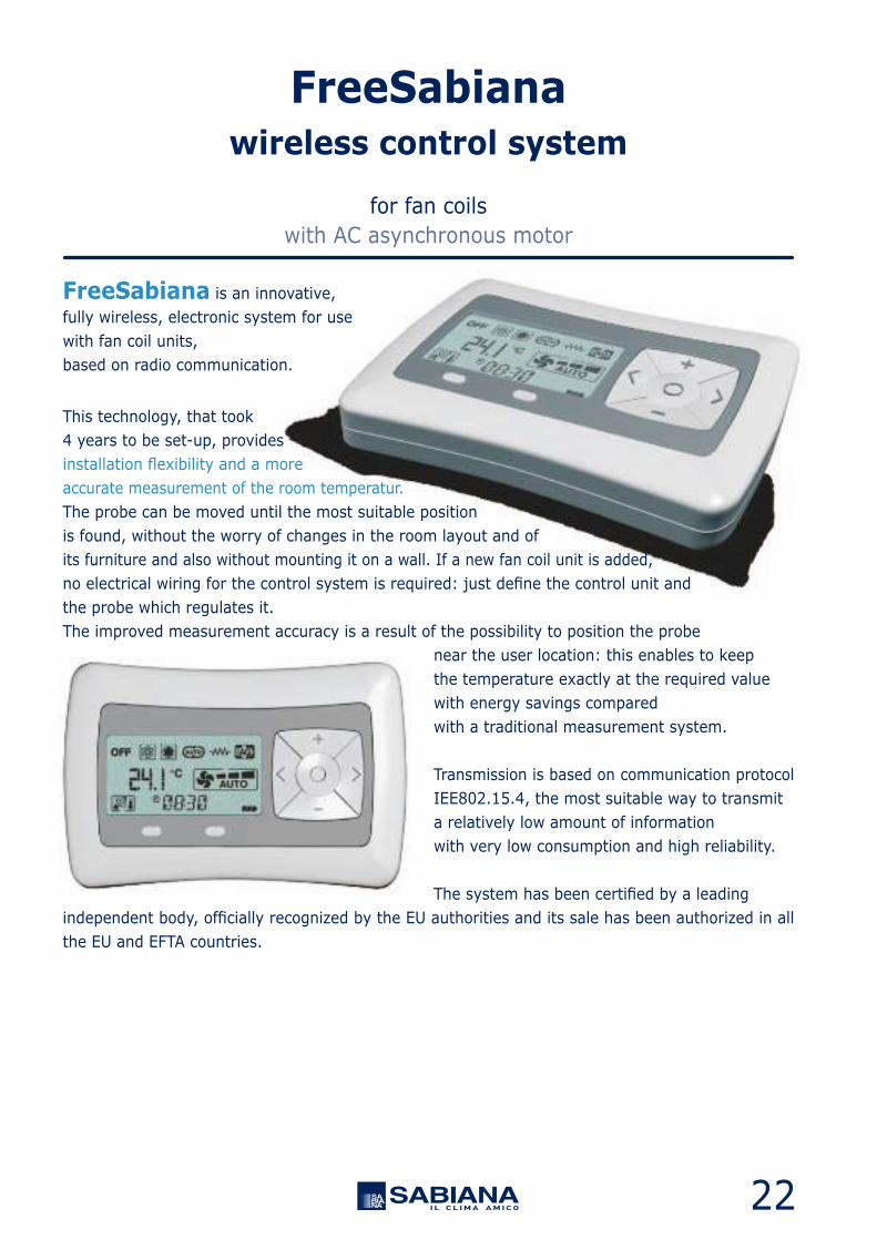
FreeSabiana is an innovative,fully wireless, electronic system for usewith fan coil units,based on radio communication.
This technology, that took4 years to be set-up, providesinstallation flexibility and a moreaccurate measurement of the room temperatur.The probe can be moved until the most suitable positionis found, without the worry of changes in the room layout and ofits furniture and also without mounting it on a wall. If a new fan coil unit is added,no electrical wiring for the control system is required: just define the control unit andthe probe which regulates it.The improved measurement accuracy is a result of the possibility to position the probe
near the user location: this enables to keepthe temperature exactly at the required valuewith energy savings comparedwith a traditional measurement system.
Transmission is based on communication protocolIEE802.15.4, the most suitable way to transmita relatively low amount of informationwith very low consumption and high reliability.
The system has been certified by a leadingindependent body, officially recognized by the EU authorities and its sale has been authorized in allthe EU and EFTA countries.
for fan coilswith AC asynchronous motor
FreeSabianawireless control system

23
Remote control
• A remote control which features a button panel and LCD display and can be wall mounted or positioned on a dedicated table support.• It enables the control of all the operating variables of the fan coil units in different configurations. The control is battery powered.• The temperature and the operating speed of the fan coil unit are set with two large buttons featuring user friendly graphics.• It allows to run by a maximum of 25 units divided into a maximum of 4 areas with different temperatures.
Power unit
• A power unit to be installed on the fan coil (fan coil interface).• It controls the fan and the valves of the fan coil. The power unit is connected to the electric supply.• The power unit receives the information required to control the fan coil both from the remote control and locally, such as the temperature of the coil.
Temperature probe
• A room temperature probe, which can be wall mounted or positioned on a dedicated table support.• It is a battery powered device, able to measure the air temperature in the spot where it is positioned, generating temperature information which is communicated to the other devices.
Only one Free-Sen per area.
Main components:
Free-Com
Free-Sen
Identification
Identification
9060572
9060573
Code
Code
Free-Upm (mounted)
Free-Usm (mounted)
Free-Ups (not mount.)
Identification
9060571
9079107
9060570
Code
for fan coilswith AC asynchronous motor
FreeSabianawireless control system
To combine with: CRC CRT CRR CRSO SK CCN CVP MVI
for Carisma fan coils
for SkyStar fan coils

24
B2 B1B4
C2
C3C1 AB3
Affiliation system
Mesh network
The communication protocol has been developed using multi-centre Meshnetwork logic, where each unit can exchange information with the nearbyunits.If a node fails, the other nodes can replace it, automatically reroutinginformation.This way, it is possible to realize redundant paths which increase the overallreliability of the system.
Before transmitting information, the system looks for most stable of the 16available channels and waits for a “return receipt”, that is a confirmation ofthe successful transmission of the information.
All the power unit s on the fan coil unit s continuously transmit any informationreceived to all the components of the network, greatly increasing transmissionreliability.
The maximum number of fan coil units which can be controlled by a singlecontrol unit is 25, with the possibility to control up to four zones with differenttemperatures.In the same building there can be several control units, that is severalnetworks.
The affiliation procedure (the definition of which units are controlled by thecontrol unit and by the probe) is quite simple and is carried out duringsystem commissioning by means of a cable (provided) to be inserted inthe specific connectors.
Battery life depends on the frequency of control parameters changes.Indicatively it last for 12 months.
If a control unit needs to be replaced, for instance due to an accidental fall,during the connection of the new control by cable to the fan coil unit, allthe information about the network structure is transferred to the controlunit, without having to redefine all the network components and all thetemperature/operating values set.
The receiving power of the signal, as maximum distance among eachitem of the network, is of:• 12 metres for the normal floor installations;• 8 metres for the normal floor installations within brick walls or drywall;• 6 metres for the normal concealed installations (false ceilings,etc.).
Radio communication among the components:
for fan coilswith AC asynchronous motor
FreeSabianawireless control system

25
12 10 11 138
1 2 3 7 4 5 6
9
It enables the following main actions:• Fan coil ON/OFF switching.• Fan speed selection (high - medium - low – automatic).• Summer/winter operation selection.• Valve ON/OFF.• Real time clock setting.• Temperature setting.• Daily switch ON/OFF setting (timer function).• Enable/disable the timer function.• Activation of the (optional) electrostatic filter.• Activation of the (optional) electric heater.
Main information displayed:1) ON/OFF status2) Summer operation3) Winter operation4) Automatic season change5) Electric heater6) Electrostatic filter7) Room temperature (with decimal accuracy)
8) Fan operating speed9) Required / measured temperature10) Timer11) Clock12) Transmission signal13) Battery level
The power unit controls the fan and the valves of the fan coil.The power unit receives the information required to control such units both from the remotecontrol and locally.
It enables the following main actions:• Fan ON/OFF at a set speed.• Fan speed change (fan ON/OFF).• Water valve/s ON/OFF (1 valve for 2 tube system- 2 valves for 4 tube system).• Fan speed change operating the water valve/s.• Control of the electric heater as main heating unit or as integration to the battery supplied with hot water.• Control of the operation of the electrostatic filter (in parallel to the fan).• Management of the dead zone function for 4-tube systems.• Available functional inputs: - Consent for remote ON/OFF; - Consent for remote Summer/Winter switch (centralized); - Consent for the activation of the energy saving function with setting change; - Minimum probe; - Probe for season change.
This device is able to measure the temperature of the air in the spot where it is positioned andto transmit it by means of radio communication to the other devices in the system.It is battery powered and can be freely positioned at a maximum of 6 metres distant from theUP-AU power unit in the area to be air-conditioned.
Display:• Measured environment temperature. • Transmission signal.• Clock. • Battery status.
Main features of the remote control:
Main features of the power unit to be installed on the fan coil:
Main features of the temperature sensor:
for fan coilswith AC asynchronous motor
FreeSabianawireless control system

26
To combine with:CRC CRT CRR CRSO SK CCN CVP-MB
CRC-ECM CRT-ECM MVI CRS-ECM SK-ECM CCN-ECM CVP-ECM-MB
MB boardThe MB electronic board is set to carry out different functions and adjustment modes, in orderto meet the installation requirements.These modes are selected by setting the configuration dip switches on the board.• 2/4 pipe system.• Fan ON/OFF thermostatic control.• Valve ON/OFF thermostatic control and continuous ventilation.• Valve and simultaneous ventilation ON/OFF thermostatic control.• Fan operation control depending on the coil temperature (cut-out T3 probe fitted), which can be activated only in heating mode or heating and cooling mode.• Automatic switch of the operating mode by means of T2 water probe (optional) applied on the 2 pipe system.• Seasonal switch by means of remote contact.• ON/OFF of the fan coil by means of the remote contact (window or clock contact).• Electric heater or Crystall electronic filter control (the simultaneous control of the heater and of the Crystall filter is not possible).
By activating the cut-out T3 probe function, the fan is stopped in winter when the coil temperatureis lower than 32°C and started when the temperature reaches 36°C. In summer mode, the fanstops when the temperature inside the coil exceeds 22°C and starts when it drops below 18°C.
The following connections are located on the power board:• Receiver for infra-red remote control.• T-MB control.• RS 485 serial connection to manage several fan coils in Master/Slave configuration or to create a supervisory network.
NTC sensor included for T1 function (return air control).NTC sensor included for T3 function (low temperature cut-out thermostat).NTC sensor (option) for T2 function (summer/winter switch).
MB-M (mounted)
MB-S (not mounted)
MB-ECM-M (mounted)
MB-ECM-S (not mount.)
Identification
9066332
9066333
9066334
9066335
Code
All the Carisma units can be supplied with a wide range of controls,which allows managing one single unit or several units by using the Modbus RTU - RS 485 communication protocol.
Units can be managed according to the Master/Slave logic (up to 20 units) or by supervisory component.The system consists in a MB board and a series of controls, such as the T-MB control,
the RT03 infra-red remote control, the PSM-DI multifunction control and the Sabianet supervisory program.
for the Carisma fan coil rangewith AC asynchronous motor and with EC electronic motor and inverter board
To be mountedon the fan coil internal unit.
Fitted on the unit forCVP-MB and CVP-ECM-MB
MBcontrols and units
with electric asynchronous motor
with electronic motor and inverter board
27
To combine with:CRC CRT CRR CRSO SK CCN CVP-MB
CRC-ECM CRT-ECM MVI CRS-ECM SK-ECM CCN-ECM CVP-ECM-MB
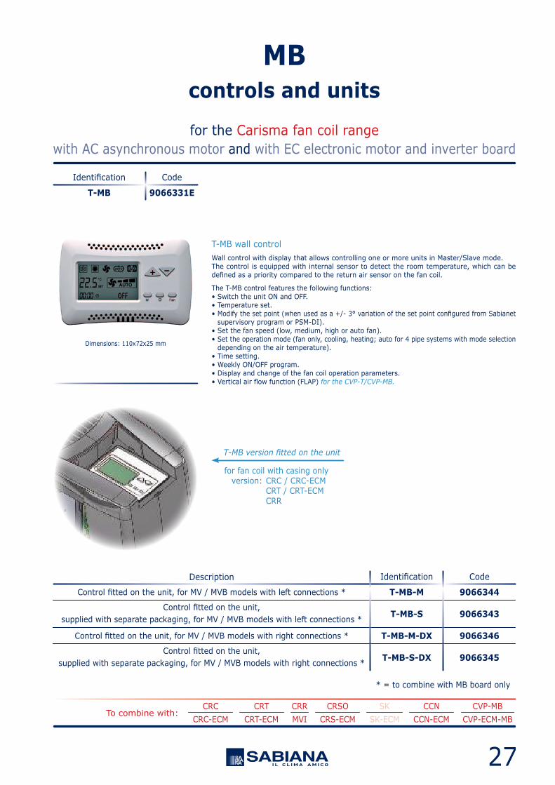
T-MB wall controlWall control with display that allows controlling one or more units in Master/Slave mode.The control is equipped with internal sensor to detect the room temperature, which can bedefined as a priority compared to the return air sensor on the fan coil.
The T-MB control features the following functions:• Switch the unit ON and OFF.• Temperature set.• Modify the set point (when used as a +/- 3° variation of the set point configured from Sabianet supervisory program or PSM-DI).• Set the fan speed (low, medium, high or auto fan).• Set the operation mode (fan only, cooling, heating; auto for 4 pipe systems with mode selection depending on the air temperature).• Time setting.• Weekly ON/OFF program.• Display and change of the fan coil operation parameters.• Vertical air flow function (FLAP) for the CVP-T/CVP-MB.
Dimensions: 110x72x25 mm
T-MB
Identification
9066331E
Code
for fan coil with casing only version: CRC / CRC-ECM CRT / CRT-ECM CRR
* = to combine with MB board only
T-MB-M
T-MB-S
T-MB-M-DX
T-MB-S-DX
Control fitted on the unit, for MV / MVB models with left connections *
Control fitted on the unit,supplied with separate packaging, for MV / MVB models with left connections *
Control fitted on the unit, for MV / MVB models with right connections *
Control fitted on the unit,supplied with separate packaging, for MV / MVB models with right connections *
IdentificationDescription
9066344
9066343
9066346
9066345
Code
for the Carisma fan coil rangewith AC asynchronous motor and with EC electronic motor and inverter board
MBcontrols and units
T-MB version fitted on the unit
28
To combine with:CRC CRT CRR CRSO SK CCN CVP-MB
CRC-ECM CRT-ECM MVI CRS-ECM SK-ECM CCN-ECM CVP-ECM-MB
RT03 infra-red remote control with fitted receiver, for MV / MO-MVB models *
RT03 infra-red remote control with receiver supplied with separate packaging *
RT03 infra-red remote control with receiver supplied with separate packaging *
Receiver for RT03 infra-red remote control fitted on the unit, for MV / MO-MVB models *
Receiver for RT03 infra-red remote control supplied with separate packaging *
Receiver for RT03 infra-red remote control supplied with separate packaging(to be used with MB board only) – only for CVP-T-MB fan coil units
Receiver for RT03 infra-red remote control supplied with separate packaging(to be used with MB board only) – only for CVP-T-MB fan coil units
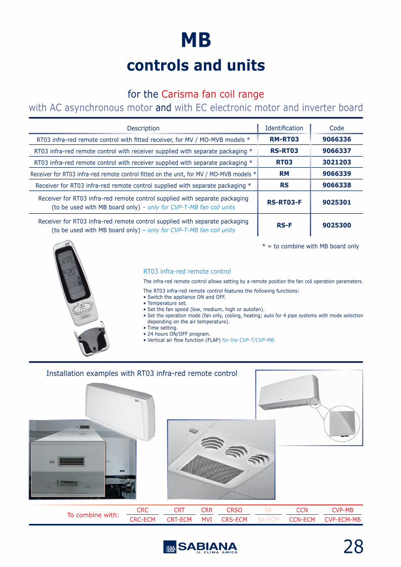
RT03 infra-red remote controlThe infra-red remote control allows setting by a remote position the fan coil operation parameters.
The RT03 infra-red remote control features the following functions:• Switch the appliance ON and OFF.• Temperature set.• Set the fan speed (low, medium, high or autofan).• Set the operation mode (fan only, cooling, heating; auto for 4 pipe systems with mode selection depending on the air temperature).• Time setting.• 24 hours ON/OFF program.• Vertical air flow function (FLAP) for the CVP-T/CVP-MB.
for the Carisma fan coil rangewith AC asynchronous motor and with EC electronic motor and inverter board
MBcontrols and units
Installation examples with RT03 infra-red remote control
RM-RT03
RS-RT03
RT03
RM
RS
RS-RT03-F
RS-F
* = to combine with MB board only
IdentificationDescription
9066336
9066337
3021203
9066339
9066338
9025301
9025300
Code

29
To combine with:CRC CRT CRR CRSO SK CCN CVP-MB
CRC-ECM CRT-ECM MVI CRS-ECM SK-ECM CCN-ECM CVP-ECM-MB
A group of Carisma units with MB electronic board can be connected via a serial link and can consequentlybe managed at the same time by just one T-MB control or RT03 infra-red remote control.
Using the special jumper present on the MB board, one unit must be configured as the master, and all the others as slaves. It is clear that the remote control must be pointed at the receiver on the master unit.
To avoid problems, it is recommended to install and connect the receiver only on the master unit.
With T-MB control
With RT03 infra-red remote control
One control for each unit(Maximum length of the connection cable = 20 m)
One control for each unit
One control for more units (20 units max.)(Maximum total length of the connection cable = 800 m)
One control for more units (20 units max.)(Maximum total length of the connection cable = 800 m)
T2 accessory for units with MB electronic boardThe T2 sensor can be combined with MB boards to be placed on the water supply pipe upstream 3 way valves(not to be used with 2 way valve).
The T2 sensor must be used as described below:
• Change-Over for 2-pipe system for the automatic switch of the operating mode. If water temperature is lower than 20°C, cooling mode is set; on the other hand, if water temperature exceeds 30°C, heating mode is set.• It can be used on units with electric heater and hot water supply. The T2 priority probe activates the electric heater or water valve, depending on the water temperature detected. If water temperature exceeds 34°C, the water valve ON-OFF control is activated; on the other hand, if water temperature is lower than 30°C, the electric heater is activated.
T2
Identification
9025310
Code
for the Carisma fan coil rangewith AC asynchronous motor and with EC electronic motor and inverter board
MBcontrols and units
Belden Cable 9841
Belden Cable 9841

30
To combine with:CRC CRT CRR CRSO SK-MB CCN CVP
CRC-ECM CRT-ECM MVI CRS-ECM SK-ECM-MB CCN-ECM CVP-ECM
mountedas per standard
MB boardThe MB electronic board, to be mounted on the SK-MB and SK-ECM-MB versions, is set to carryout different functions and adjustment modes, in order to meet the installation requirements.These modes are selected by setting the configuration dip switches on the board.• 2/4 pipe system.• Fan ON/OFF thermostatic control.• Valve ON/OFF thermostatic control and continuous ventilation.• Valve and simultaneous ventilation ON/OFF thermostatic control.• Fan operation control depending on the coil temperature (cut-out T3 probe fitted), which can be activated only in heating mode or heating and cooling mode.• Automatic switch of the operating mode by means of T2 water probe (optional) applied on the 2 pipe system.• Seasonal switch by means of remote contact.• ON/OFF of the fan coil by means of the remote contact (window or clock contact).• Electric heater or Crystall electronic filter control (the simultaneous control of the heater and of the Crystall filter is not possible).
By activating the cut-out T3 probe function, the fan is stopped in winter when the coil temperatureis lower than 32°C and started when the temperature reaches 36°C. In summer mode, the fanstops when the temperature inside the coil exceeds 22°C and starts when it drops below 18°C.
The following connections are located on the power board:• Receiver for infra-red remote control.• T-MB control.• RS 485 serial connection to manage several fan coils in Master/Slave configuration or to create a supervisory network.
All the Cassette units with MB electronic board can be supplied with a wide range of controls,which allows managing one single unit or several units by using the Modbus RTU - RS 485 communication protocol.
Units can be managed according to the Master/Slave logic (up to 20 units) or by supervisory components.The system consists in a MB board and a series of controls, such as the T-MB control,
the RT03 infra-red remote control, the PSM-DI multifunction control and the Sabianet supervisory program.
for the SkyStar SK-MB / SK-ECM-MB fan coil rangeswith AC asynchronous motor and with EC electronic motor and inverter board
MBcontrols and units

31
To combine with:CRC CRT CRR CRSO SK-MB CCN CVP
CRC-ECM CRT-ECM MVI CRS-ECM SK-ECM-MB CCN-ECM CVP-ECM
Dimensions: 110x72x25 mm
T-MB wall controlWall control with display that allows controlling one or more units in Master/Slave mode.The control is equipped with internal sensor to detect the room temperature, which can bedefined as a priority compared to the return air sensor on the fan coil.
The T-MB control features the following functions:• Switch the unit ON and OFF.• Temperature set.• Modify the set point (when used as a +/- 3° variation of the set point configured from Sabianet supervisory program or PSM-DI).• Set the fan speed (low, medium, high or auto fan).• Set the operation mode (fan only, cooling, heating; auto for 4 pipe systems with mode selection depending on the air temperature).• Time setting.• Weekly ON/OFF program.• Display and change of the fan coil operation parameters.
T-MB
Identification
9066331E
Code
for the SkyStar SK-MB / SK-ECM-MB fan coil rangeswith AC asynchronous motor and with EC electronic motor and inverter board
MBcontrols and units

32
To combine with:CRC CRT CRR CRSO SK-MB CCN CVP
CRC-ECM CRT-ECM MVI CRS-ECM SK-ECM-MB CCN-ECM CVP-ECM
for the SkyStar SK-MB / SK-ECM-MB fan coil rangeswith AC asynchronous motor and with EC electronic motor and inverter board
MBcontrols and units
The infra-red remote control allows setting by a remote position the fan coil operation parameters.
The RT03 infra-red remote control features the following functions:• Switch the appliance ON and OFF.• Temperature set.• Set the fan speed (low, medium, high or autofan).• Set the operation mode (fan only, cooling, heating; auto for 4 pipe systems with mode selection depending on the air temperature).• Time setting.• 24 hours ON/OFF program.
RCS-RT03
RCS
RS
RT03 infra-red remote control with receiver supplied with separate packaging(to be used with SK-MB and SK-ECM-MB version only)
Receiver for RT03 infra-red remote control supplied with separate packaging(to be used with SK-MB and SK-ECM-MB version only)
Receiver for RT03 infra-red remote control and MD-600 metal diffuser suppliedwith separate packaging (to be used with SK-MB and SK-ECM-MB version only)
IdentificationDescription
9079117
9079116
9066338
Code
Installation exampleswith RT03 infra-red remote control
RT03RT03 infra-red remote control supplied with separate packaging
(to be used with SK-MB and SK-ECM-MB version only)
IdentificationDescription
3021203
Code
RCS-RT03RCS
33
To combine with:CRC CRT CRR CRSO SK-MB CCN CVP
CRC-ECM CRT-ECM MVI CRS-ECM SK-ECM-MB CCN-ECM CVP-ECM
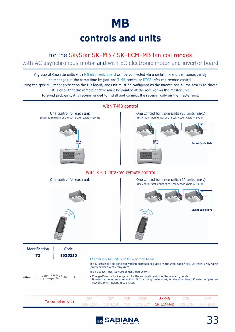
A group of Cassette units with MB electronic board can be connected via a serial link and can consequentlybe managed at the same time by just one T-MB control or RT03 infra-red remote control.
Using the special jumper present on the MB board, one unit must be configured as the master, and all the others as slaves. It is clear that the remote control must be pointed at the receiver on the master unit.
To avoid problems, it is recommended to install and connect the receiver only on the master unit.
With T-MB control
With RT03 infra-red remote control
One control for each unit(Maximum length of the connection cable = 20 m)
One control for each unit
One control for more units (20 units max.)(Maximum total length of the connection cable = 800 m)
One control for more units (20 units max.)(Maximum total length of the connection cable = 800 m)
T2 accessory for units with MB electronic boardThe T2 sensor can be combined with MB boards to be placed on the water supply pipe upstream 3 way valves(not to be used with 2 way valve).
The T2 sensor must be used as described below:
• Change-Over for 2-pipe system for the automatic switch of the operating mode. If water temperature is lower than 20°C, cooling mode is set; on the other hand, if water temperature exceeds 30°C, heating mode is set.
T2
Identification
9025310
Code
for the SkyStar SK-MB / SK-ECM-MB fan coil rangeswith AC asynchronous motor and with EC electronic motor and inverter board
MBcontrols and units
Belden Cable 9841
Belden Cable 9841
34
To combine with:CRC CRT CRR CRSO SK-MB CCN CVP-MB
CRC-ECM CRT-ECM MVI CRS-ECM SK-ECM-MB CCN-ECM CVP-ECM-MB
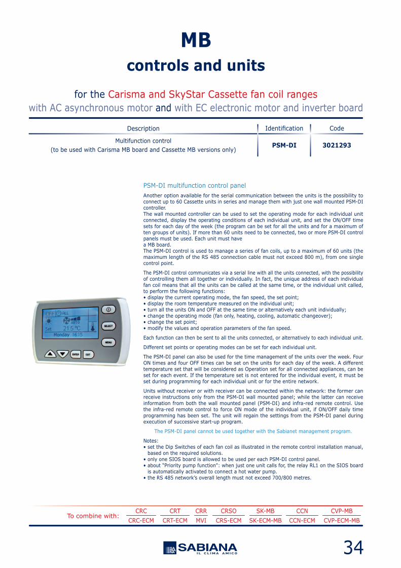
PSM-DI multifunction control panelAnother option available for the serial communication between the units is the possibility toconnect up to 60 Cassette units in series and manage them with just one wall mounted PSM-DIcontroller.The wall mounted controller can be used to set the operating mode for each individual unitconnected, display the operating conditions of each individual unit, and set the ON/OFF timesets for each day of the week (the program can be set for all the units and for a maximum often groups of units). If more than 60 units need to be connected, two or more PSM-DI controlpanels must be used. Each unit must havea MB board.The PSM-DI control is used to manage a series of fan coils, up to a maximum of 60 units (themaximum length of the RS 485 connection cable must not exceed 800 m), from one singlecontrol point.
The PSM-DI control communicates via a serial line with all the units connected, with the possibilityof controlling them all together or individually. In fact, the unique address of each individualfan coil means that all the units can be called at the same time, or the individual unit called,to perform the following functions:• display the current operating mode, the fan speed, the set point;• display the room temperature measured on the individual unit;• turn all the units ON and OFF at the same time or alternatively each unit individually;• change the operating mode (fan only, heating, cooling, automatic changeover);• change the set point;• modify the values and operation parameters of the fan speed.
Each function can then be sent to all the units connected, or alternatively to each individual unit.
Different set points or operating modes can be set for each individual unit.
The PSM-DI panel can also be used for the time management of the units over the week. FourON times and four OFF times can be set on the units for each day of the week. A differenttemperature set that will be considered as Operation set for all connected appliances, can beset for each event. If the temperature set is not entered for the individual event, it must beset during programming for each individual unit or for the entire network.
Units without receiver or with receiver can be connected within the network: the former canreceive instructions only from the PSM-DI wall mounted panel; while the latter can receiveinformation from both the wall mounted panel (PSM-DI) and infra-red remote control. Usethe infra-red remote control to force ON mode of the individual unit, if ON/OFF daily timeprogramming has been set. The unit will regain the settings from the PSM-DI panel duringexecution of successive start-up program.
The PSM-DI panel cannot be used together with the Sabianet management program.
Notes:• set the Dip Switches of each fan coil as illustrated in the remote control installation manual, based on the required solutions.• only one SIOS board is allowed to be used per each PSM-DI control panel.• about “Priority pump function": when just one unit calls for, the relay RL1 on the SIOS board is automatically activated to connect a hot water pump.• the RS 485 network’s overall length must not exceed 700/800 metres.
PSM-DIMultifunction control
(to be used with Carisma MB board and Cassette MB versions only)
IdentificationDescription
3021293
Code
for the Carisma and SkyStar Cassette fan coil rangeswith AC asynchronous motor and with EC electronic motor and inverter board
MBcontrols and units

35
To combine with:CRC CRT CRR CRSO SK-MB CCN CVP-MB
CRC-ECM CRT-ECM MVI CRS-ECM SK-ECM-MB CCN-ECM CVP-ECM-MB
Sabianet programfor managing a network of Sabiana MB fan coilsSabianet is a centralised control system for networks of Sabiana MB fan coils, based on softwarethat runs on LINUX™ operating system (the program is provided pre-installed on a PC) and itworks in a "stand alone" way, as an ordinary computer, so that it can be connected to a monitor,to a mouse and to a keyboard. By connecting an Ethernet cable is instead possible to work ata distance and visualize the entire program setting-up through whatever browsers.The Sabianet software offers a practical and economical solution for managing the units, withthe simple click of the mouse.
The main characteristics are:• simplicity of use;• an extremely complete and functional weekly program;• possibility to access the historical operating data for each individual unit connected;• possibility to save automatically every 6 h the data on SD support and to force the saving with a button;• possibility of data saving also on other items, as for example USB key-boards;• visualization of the saved configuration on a new ASUS PC.
The program exploits all the potential of our units with remote controls, representing an additionto the latter.
The Sabianet program is a control tool that can be used as a replacement for the remote control,or in parallel, however the settings made using Sabianet can have priority over those made usingthe remote control or T-MB.
The program can be used to:• Create uniform groups (groups of units on individual floors, in offices or rooms).• Save weekly programs configured for different types of operation (summer, winter, mid seasons, closing periods etc.); these can then be recalled and activated with a simple click of the mouse. Weekly on/off cycles can be set for individual units or groups of units.• Set the operating conditions for each individual unit or groups of units (operating mode, fan speed, temperature setting).• Set the set point limits for each individual unit or groups of units.• Switch each individual unit or groups of units ON or OFF.
SabianetHardware/software supervisory system
(to be used with Carisma MB board and Cassette MB versions only)
IdentificationDescription
9079118
Code
for the Carisma and SkyStar Cassette fan coil rangeswith AC asynchronous motor and with EC electronic motor and inverter board
SABIANET program for managinga network of Sabiana MB fan coils

36
The main program screen can display and interact with the entire network of units.An individual unit, a group of units or the entire network can be called so as to make modifications to the operating mode and the set point.
The user can then check the operating status of each individual unit, read the room temperature, the coil temperatureand the operating status of the condensate drain pump or any alarms.
Carisma “MONITORING" Screen
SkyStar “MONITORING" Screen
The icon of the terminal unitprovides the following information:- Unit name (00.01.01)- Set temperature (SETP)- Room temperature (AT)
- Unit status: ON or OFF
- Mode: • Summer • Winter • Auto • Fan only
- Fan speed: • Low • Medium • High • Auto Fan
Displaying a unitThe “MONITORING” Screen showsthe units that are connected to the networkand scanned by the program.
for the Carisma and SkyStar Cassette fan coil rangeswith AC asynchronous motor and with EC electronic motor and inverter board
SABIANET program for managinga network of Sabiana MB fan coils

37
The “Weekly Program” can be used to set the unit operating parameters for each day of the week.Several weekly programs can be set Time bands are available for each day of the week.
The time and the type of operation to be performed by the unit can be set for each band.The time and the operating parameters can then be displayed before being sent to the unit and implemented.
“EVENT MANAGEMENT" Screen
Displaying of the parameters and Dip Switches set upEvery time that the reading of the set up Dip Switches results not easy (as for example by the false ceiling installations),
it is always possible to display them directly through the Sabianet program.
for the Carisma and SkyStar Cassette fan coil rangeswith AC asynchronous motor and with EC electronic motor and inverter board
SABIANET program for managinga network of Sabiana MB fan coils

38
USB-RS 485CONVERTER
SABIANET
60 units max. (*)
RS 485Jumper MC2 to be closed.
End of network.
Outputsfor system
Powerinput
Outputsfor system
Powerinput
Outputsfor system
Powerinput
RS 485 serial connection cableShielded cable to be used: Belden 9841, RS-485, 1x2x24 AWG SFTP, 120 Ohm.
PC Sabianet SoftwareInstallation example with a SkyStar network with MB board.
(*) In the event of more than 60 units, add one or more Router-S (see next page).
for the Carisma and SkyStar Cassette fan coil rangeswith AC asynchronous motor and with EC electronic motor and inverter board
SABIANET program for managinga network of Sabiana MB fan coils
Alarm control by E-mail and smsIn addition to the alarm set on the Sabianet display, it is possible to send the ON-OFF alarm notification via E-mail and sms.

for the Carisma and SkyStar Cassette fan coil rangeswith AC asynchronous motor and with EC electronic motor and inverter board
Accessories for BMS systemswhich are not provided by Sabiana
for the Carisma and SkyStar Cassette fan coil rangeswith AC asynchronous motor and with EC electronic motor and inverter board
MB and SABIANETaccessories
39
INDEX• Controls by Sabiana Page 3
• Overview of the controls: - Controls fitted on the unit with AC asynchronous motor Page 4 - Wall controls with AC asynchronous motor Page 6 - Wall controls and fitted on the unit with EC electronic motor Page 8
• Description of the controls: - Controls fitted on the unit with AC asynchronous motor Page 10 - Controls fitted on the unit for fan coils with AC asynchronous motor, Crystall electronic filter or electric heater Page 12 - Controls fitted on the unit with EC electronic motor and inverter board Page 13 - Wall controls with AC asynchronous motor Page 14 - Wall controls unit with EC electronic motor and inverter board Page 17
• Power unit and speed switches Page 18
• Accessories Page 20
• FreeSabiana wireless control system Page 22
• MB controls and units Page 26
• SABIANET management system for a network of fan coils Page 35
• MB and SABIANET accessories Page 39
• Accessories for BMS systems which are not provided by Sabiana Page 39
The descriptions and illustrations provided in this publication are not binding:
Sabiana reserves the right, whilst maintaining the essential characteristics
of the types described and illustrated, to make, at any time,
without the requirement to promptly update this piece of literature,
any changes that it considers useful for the purpose of improvement
or for any other manufacturing or commercial requirements.
For technical details read carefullythe manual of installation, use and maintenance.
To combine with:
To combine with:
CRC
CRC
CRT
CRT
CRR
CRR
CRSO
CRSO
SK-MB
SK-MB
CCN
CCN
CVP-MB
CVP-MB
CRC-ECM
CRC-ECM
CRT-ECM
CRT-ECM
MVI
MVI
CRS-ECM
CRS-ECM
SK-ECM-MB
SK-ECM-MB
CCN-ECM
CCN-ECM
CVP-ECM-MB
CVP-ECM-MB
Router-SThe Router-S is an electronic board that:• allows creating networks with more than 60 units (minimum 2 Router-S are required) or to divide the network (per floor, building, etc.).• it allows creating a Master/Slave sub-network to be controlled as an indipendent group.
The Router-S can be used only inside a network managed by Sabianet.
The number of Router-S to be used is: • up to 60 units: no Router-S. • from 61 to 120 units: 2 Router-S. • every 60 subsequent units: 1 additional Router-S.
Router-BMSThe Router-BMS (ModBus) is an electronic board to use with BMS systems not supplied bySabiana:• it allows to set-up a Master/Slave sub-network to check as an indipendent network.
The number of Router-BMS (ModBus) to use is:• maximum 14 Router-BMS.• maximum 15 fan coils per Router-BMS.
SIOSSIOS is a board equipped with 8 relays with potential free contact to control the activation ordeactivation of remote electric utilities. Moreover, the board has 8 digital inlets to display theactuators or external consents, such as motor or other.
The SIOS boards can be connected:• inside a network managed by Sabianet.• to a PSM-DI panel (one SIOS for each PSM-DI panel).
Router-S
Router-BMS
SIOS
Identification
Identification
Identification
3021290
3021340
3021292
Code
Code
Code

Fan CoilControl Range
CONT
ROLS
- 0
3/16
COd.
99A
4CC0
100
A/0
3/16
Sabiana s.p.a. • via Piave, 53 • 20011 Corbetta • Milano • Italyphone +39.02.97203.1 r.a. / +39.02.97270429 / +39.02.97270576 • fax +39.02.9777282 / +39.02.9772820
www.sabiana.it • [email protected]