Failure analysis of fiber-reinforced composites subjected ...
18
1 Failure analysis of fiber-reinforced composites subjected to coupled thermo-mechanical loading Junjie Ye a,b , Yiwei Wang a , Ziwei Li a , Mohammed Saafi b , Fei Jia a , Bo Huang b , Jianqiao Ye b* a Research Center for Applied Mechanics, Key Laboratory of Ministry of Education for Electronic Equipment Structure Design, Xidian University, Xi’an 710071, China b Department of Engineering, Lancaster University, Lancaster LA1 4YW, UK Abstract Structures made of fiber reinforced composites have captured extensive attentions in the scientific and engineering communities due to their excellent performance and applicability. When these structures are in service, they are likely exposed to variations of ambient temperature that may have an impact on their strength. To study this effect, a coupled thermo-mechanical model is required. This paper develops a microscopic mechanical model to investigate failure of composite structures subjected to a coupled thermo-mechanical condition. Stiffness degradations of composite laminates are first investigated. A comparison between experimental data and theoretical results under the quasi-static loadings are presented to validate the proposed method. The method provides detailed microscopic stress distribution of the composites under the coupled thermo-mechanical loading for failure analysis, which shows that a higher ambient temperature variation will generally cause stiffness degradation and failure strength for both uniaxially and biaxially loaded laminates. Keywords: Composites, failure strength, thermo-mechanical failures, micromechanics. 1. Introduction Composite materials have been widely used in aviation and wind turbine industry over the past decades [1-3] due to their relatively lower cost and higher performance. However, as any other engineering materials, structural failure of composites occurs when they are subjected to mechanical loading, especially, under varying environmental conditions, such as changes in temperature. For instance, a wind turbine is normally subjected to repeated changes in temperature due to temperature variations between day and night. Therefore, how to accurately predict failure of composite materials with consideration of temperature variations has become an attractive, but challenging subject [4]. Studies on coupled thermo-mechanical responses of materials, which play an important role in structural health monitoring and optimal design of composites, have attracted great interests from both engineers and academic researchers [5-7]. Discussions on the effects of thermal stresses [8-9], thermal aging [10-12], sintering temperature [13] and thermal expansion [14] on the properties of composite materials have been reported by many investigators. Based on the scanning electron microscope (SEM) micrographs, Li et al. [15] studied the failure mechanisms of composite materials at room and elevated temperatures. Yang et al. [16] investigated transverse tensile behavior of carbon fiber-reinforced composites by experimental and theoretical methods at five different ambient temperatures. The results shown that transversal failure modes depended closely on the residual thermal stresses. Hu et al. [17] studied the influence of fiber contents and carbon nanotubes coatings on the mechanical and thermal properties of composites. The experimental results indicated that an increase of carbon fiber content will effectively enhance the tensile and flexural properties, as well as the hardness of composites. Composite structures are normally exposed to long-term thermo-mechanical loading environment, and likely to experience temperature-dependent failures. However, most of the studies on thermal-mechanical properties of composite materials are limited
Transcript of Failure analysis of fiber-reinforced composites subjected ...

1
Failure analysis of fiber-reinforced composites subjected to
coupled thermo-mechanical loading
Junjie Yea,b, Yiwei Wanga, Ziwei Lia, Mohammed Saafib, Fei Jiaa, Bo Huangb, Jianqiao Yeb*
a Research Center for Applied Mechanics, Key Laboratory of Ministry of Education for Electronic Equipment Structure Design, Xidian University, Xi’an 710071, China b Department of Engineering, Lancaster University, Lancaster LA1 4YW, UK Abstract
Structures made of fiber reinforced composites have captured extensive attentions in the scientific and engineering communities due to their excellent performance and applicability. When these structures are in service, they are likely exposed to variations of ambient temperature that may have an impact on their strength. To study this effect, a coupled thermo-mechanical model is required. This paper develops a microscopic mechanical model to investigate failure of composite structures subjected to a coupled thermo-mechanical condition. Stiffness degradations of composite laminates are first investigated. A comparison between experimental data and theoretical results under the quasi-static loadings are presented to validate the proposed method. The method provides detailed microscopic stress distribution of the composites under the coupled thermo-mechanical loading for failure analysis, which shows that a higher ambient temperature variation will generally cause stiffness degradation and failure strength for both uniaxially and biaxially loaded laminates. Keywords: Composites, failure strength, thermo-mechanical failures, micromechanics.
1. Introduction
Composite materials have been widely used in aviation and wind turbine industry over the past decades [1-3] due to their relatively lower cost and higher performance. However, as any other engineering materials, structural failure of composites occurs when they are subjected to mechanical loading, especially, under varying environmental conditions, such as changes in temperature. For instance, a wind turbine is normally subjected to repeated changes in temperature due to temperature variations between day and night. Therefore, how to accurately predict failure of composite materials with consideration of temperature variations has become an attractive, but challenging subject [4].
Studies on coupled thermo-mechanical responses of materials, which play an important role in structural health monitoring and optimal design of composites, have attracted great interests from both engineers and academic researchers [5-7]. Discussions on the effects of thermal stresses [8-9], thermal aging [10-12], sintering temperature [13] and thermal expansion [14] on the properties of composite materials have been reported by many investigators. Based on the scanning electron microscope (SEM) micrographs, Li et al. [15] studied the failure mechanisms of composite materials at room and elevated temperatures. Yang et al. [16] investigated transverse tensile behavior of carbon fiber-reinforced composites by experimental and theoretical methods at five different ambient temperatures. The results shown that transversal failure modes depended closely on the residual thermal stresses. Hu et al. [17] studied the influence of fiber contents and carbon nanotubes coatings on the mechanical and thermal properties of composites. The experimental results indicated that an increase of carbon fiber content will effectively enhance the tensile and flexural properties, as well as the hardness of composites. Composite structures are normally exposed to long-term thermo-mechanical loading environment, and likely to experience temperature-dependent failures. However, most of the studies on thermal-mechanical properties of composite materials are limited

2
to investigating mechanical responses of the materials under external loadings coupled with a constant temperature.
Investigations on coupled thermomechanical properties of composites have been recently reported by Benelfellah, Sun and Farzad [18-20]. Based on the micromechanical theory, Ahmadi [21] studied failure behavior of composite materials subjected to mechanical and thermal loadings, where the numerical results agreed well the experimental studies. Leclerc et al. [22] proposed a discrete element method to simulate thermal-induced damages in composites. The coupled thermomechanical properties of 3D braided composite materials under impact loading were investigated by Liu [23]. It was revealed that plastic strain energy increased with braiding angle. Zhang and Yang [24-26] investigated bending, stiffness degradation and crack propagation in cross-ply laminates under thermal and mechanical loading. Bhattacharjee and Bajwa [27] measured thermo-mechanical properties of composites, and gel permeation chromatography was performed to investigate the changes in fiber length. Boccardi [28-29] obtained experimental results through visualization and measurement of small temperature variations coupled with cyclic bending tests. The results helped researchers to have insight views on the macromolecular interactions and interfacial micromechanics of the materials.
There is no doubt that traditional experimental methods can provide important information on the macro properties of materials and failure mechanisms of composite structures. However, they are normally costing and time consuming. In addition, failure modes of composites are complex and closely associated to their microscopic structures. Naturally, an approach based on microscopic mechanics can be very effective in solving these difficult problems [30-31]. In this respect, the High Fidelity Generalized Method of Cells (HFGMC) was proposed to evaluate anisotropic damages of composite structures [32-34]. The validated HFGMC model was further developed to solve finite deformation problems under coupled thermomechanical conditions. Aboudi et al. [35] proposed the coupled mechanical and energy equations to predict the responses of thermo-inelastic composite materials. As a result, the coupling effect of the mechanical and thermal fields was considered in the solution. Ye et al. [36] studied the effect of thermal cycling and compressive loadings on the deformations of composite laminates. From the aforementioned investigations, it was found that a lack of research on the biaxial failure strength and microscopic stress distributions of fiber-reinforced composites subjected to varying thermal loadings is evident.
The main objective of this study is to investigate failure of fiber reinforced composites subjected to uniaxial and biaxial loadings coupled with temperature variations. To this end, an appropriate representative volume element (RVE) is selected to analyze the coupled thermo-mechanical behavior of the composites. Moreover, failure criteria are developed to describe the failure of the composites at microscopic scale. The outline of this paper is as follows. A brief introduction of the coupled thermo-mechanical model based on the HFGMC is presented in Section 2. In Section 3, a failure criterion is developed for the respective constituent failures in composites. Furthermore, thermo-mechanical failures of laminated composites under axial and biaxial loadings are studied in Section 4. To study the failure mechanisms, stiffness degradations of lamina, as well as microscopic stress distributions of the RVE are both discussed in Section 5. Conclusions can be found in Section 6.
2. Coupled thermo-mechanical modelling of continuous fiber-reinforced composites
To understand thermo-mechanical failures of composites, the HFGMC is further developed in this paper. Herein a RVE is selected from a lamina of the composite laminates shown in Fig. 1(a)

3
and divided into N Nβ γ× sub-cells as shown in Fig. 1(b), where the gray and yellow sub-cells
represent the fibers and matrix materials, respectively. The constitutive equations of the composites subjected to coupled thermo-mechanical loading can be written as follows [37-38]:
( ) ( ) ( ) ( )0( ) , , 1, 2,3p p p p
ij ijkl kl ijC T T i j kσ ε α= − − = (1)
where ( )pijσ and the superscript p denote sub-cell stress components and sub-cell number,
respectively. ( )pijklC are the sub-cell stiffness constants. ( )p
klε and ( )pijα are the sub-cell strains and
thermal expansion coefficients, respectively. 0T and T denote reference and ambient temperatures,
respectively.
For each sub-cell, the equilibrium equations in the local coordinate system 2 3y y− , as shown in
Fig. 1(b), can be expressed as:
( ). 0p
ij iσ = (2)
After considering the effect of thermal strains, the equation can be written in the following matrix form, that is,
( ) ( ) ( ) ( )p p p p T= − ∆Y Z X α (3)
where ( )pY contains all sub-cell stresses. ( )pX is the sub-cell strains vector. T∆ denotes the
temperature difference between the ambient and reference temperatures. ( )pα is the vector of all
sub-cell thermal expansion coefficients.
Based on the modeling scheme of the HFGMC, the sub-cell displacement components, ( )pW , can
be further modified as the sub-cell displacements, that is,
( ) ( ) ( ) ( ) ( ) ( )(00) 2 (10) 3 (01)
p p p py yβ γ= + + + +W W W W W2 2
( )2 ( ) ( )2 ( )2 (20) 3 (02)
1 1(3 ) (3 )2 4 2 4
p ph ly yβ γβ γ− + −W W (4)
where [ ]=W εx is the average displacement components. ε and x in the bracket are the average macroscopic strains and the global coordinates. ( )
(00)pW and ( )
( ) ( 1 and 1)pij i j≥ ≥W denote the average
Fig. 1. Typical composite structures (a) Composite laminates (b) RVE
(b) (a)
Integration point
Sub-cell
Interface between fibers and matrix

4
sub-cell displacements and their high-order average sub-cell displacements, respectively. hβ and lγ are the sub-cell dimensions. 2y and 3y are the local coordinates.
During the HFGMC simulations, the sub-cell surface tractions and the average displacements are calculated. The relationship between the macroscopic average component, Y , and the sub-cell dimensions ( hβ and lγ ) can be expressed as
( )
1 1
1 N Nph l
hl
β γ
β γβ γ= =
= ∑∑Y A X (5)
where h and l are dimensions of the RVE. Detailed information of the modelling procedures and
the equations can be found in Ye and Aboudi [36-38].
3. Constituent failure criterion
We followed the following procedure to identify internal failures in composite materials. Once the sub-cell stresses or strains reach a certain threshold, internal damage occurs in the constituent materials, resulting in degradation of material stiffness and reduction in loading capacity of the structure. In order to investigate thermo-mechanical failure, an appropriate failure criterion is essential. In general, a failure criterion can be classified as mode-independent or mode-dependent [39-40]. Mode-independent failure criterions include maximum stress criterion, maximum strain criterion and Tsai-Hill criterion, etc. A typical example of mode-dependent failure criteria is the Hashin-Rotem criterion, by which failure modes of composite materials are associated with failure loads.
The maximum stress and the maximum strain criterion assume that sub-cell fails when the sub-cell stress or strain reaches a specific constituent strength, which, Obviously, are not capable of evaluating failures under complex loadings since they do not include the effect of shearing. A similar shortcoming is also found in the Hashin-Rotem criterion. Tsai-Hill criterion, however, takes into account the interactions of all the stresses. The numerical results by Lin [41] demonstrated that Tsai-Hill criterion provided better predictions to failure in comparison with other criteria. Based on these investigations mentioned above, Tsai-Hill criterion is employed here to investigate stiffness degradations and failure of composites under coupled thermo-mechanical loading in this paper. In addition, this criterion is further modified to predict failure of the microscopic sub-cells, as follows:
2 2 2( ) ( ) ( ) ( ) ( )1 2 12 1 2( ) ( ) ( ) ( )2 1p p p p p
p p p pX Y S Xσ σ τ σ σ
+ + − < (6)
where ( )
1
p
σ and ( )
2
p
σ are the sub-cell longitudinal and transversal stresses, respectively. ( )pX and
( )pY are the sub-cell longitudinal and transversal strengths, respectively. ( )12
pτ and ( )pS denote the
sub-cell shear stress and shear strength, respectively.
4. Thermo-mechanical failure of composite laminates
4.1. Properties of the constituent materials
Microscopic damages, including fiber fractures and matrix cracks, will reduce structural stiffness and load-bearing capability. To investigate thermo-mechanical failures of composite laminates, AS4 fibers and 3501 epoxy are considered in this paper. In theory, material properties are all temperature dependent. However, they are assumed to be constant and the same as those presented in Table 1,

5
as the temperature range to be considered in this paper is not large (8℃ to 38℃) and is close to the room temperature.
Table 1. Constituent material parameters at room temperature Material properties AS4 3501-6 epoxy Longitudinal elastic modulus 11E (GPa) 225 4.2 Transverse elastic modulus 22E (GPa) 15 4.2 In-plane shear modulus 12G (GPa) 15 1.576 Transverse shear modulus 23G (GPa) 7 1.576 Poisson’s ratio 0.2 0.34 Longitudinal thermal coefficient 1α (10-6/Cº) -0.5 45 Transverse thermal coefficient 2α (10-6/Cº) 15 45 Longitudinal tensile strength TX (MPa) 3350 69 Longitudinal compressive strength CX (MPa) 2500 250 Shear strength S (MPa) - 50 Yield stress(MPa) - 168.5
4.2. Multi-scale modeling of composite laminates
Fig. 2 is the flow chart of failure modeling for composite laminates under coupled thermo-mechanical loading, which has the following five main steps.
1) Define microscopic structural parameters of the composite materials, such as fiber volume, fiber shape, etc.
2) Establish the coupled thermo-mechanical model at microscopic scale on the basis of the continuity of sub-cell displacements, local equilibrium and thermal loadings.
3) Utilize the classic laminate theory to describe the failure modes of composite laminates subjected to coupled thermo-mechanical loads. Moreover, the proposed microscopic model is employed at each integration point in the UD lamina as shown in Fig. 1.
4) Apply external mechanical loadings and the varying ambient temperature and calculate the equivalent stiffness in each RVE.
5) Increase the external loading and repeated the above steps until failure occurs [34, 42]. During the calculations, the following equation of classic laminate theory is used along with the
microscopic RVE model at each integration point, that is,
=
N A Bε
M B D (7)
where N and M are the internal force and moment vectors, respectively. A and D are the in-plane and bending stiffness matrices, respectively. B is the coupling stiffness matrix between in-plane and bending deformation. ε denotes strain.

6
4.3. Model verification To study the effect of mechanical properties and ambient temperature variations on the failure of
the laminate, three different temperature conditions are considered (Fig. 3), i.e., Case (1): the laminate is subjected to constant room temperature of 23℃, Case (2): the laminate is subjected to periodically varying temperature between 28℃ and 18℃ and Case (3): the laminate is subjected to periodically varying temperature between 38℃ and 8℃. The Fiber volume fraction of the laminate is 0.6. Fig. 4 shows the stress-strain relations of the composite laminate subjected to uniaxial tensile and varying ambient temperature. The laminate having a section profile of 2[0 / 45 / 90 ]± , which has been investigated theoretically by Mayes and Cuntze [43-44], and experimentally tested by Hinton [45], was used to validate the proposed model, as shown in Fig. 4(a). It can be seen from the comparisons that the proposed method provides better predictions to the mechanical properties and the strength of the material when compared to the test results. The maximum relative error between the test results and the current predictions is less than 5%. In addition, the newly developed model provides more insights to the second stage of loading.
To further study the influences of layer sequence on the stiffness degradations, a different laminate, 2[0 / 30 / 90 ]± , is considered in Fig. 4(b). It can be seen that the influence of the considered ambient temperature variations on the failure is small. It should be noted that the
2[0 / 30 / 90 ]± laminate has a much higher uniaxial tensile strength than the 2[0 / 45 / 90 ]± one.
In more details, when the temperature is constant, laminates 2[0 / 30 / 90 ]± and 2[0 / 45 / 90 ]± have a uniaxial tensile strengths of 1067.95MPa and 757.91MPa, respectively, as shown in Fig. 5. The uniaxial tensile strengths are slightly reduced when temperature variations are considered. For instance, when the ambient temperature variation is between 8 ℃ and 38 ℃ , laminates
2[0 / 30 / 90 ]± and 2[0 / 45 / 90 ]± have a failure strengths of 1067.71MPa and 757.79 MPa, respectively. From Figs. 4(a)-(b), it is also shown that the effect of small temperature fluctuations
Yes
Relations between adjacent sub-cells
Input microscopic structural parameters, including fiber
volume, effective moduli, fiber shape
Output of failure strength of composite laminates
Classic laminate theory
No
Failure criterion
Thermo-mechanical coupled modelling at microscopic scale
Sub-cell failure Yes Sub-cell stiffness degeneration
Calculate equivalent stiffness in each RVE
Structural modeling of composite laminates
No
Fig. 2. Flow chart of failure properties of composites under the coupled
thermo-mechanical loading
All laminas failure
7
on the stiffness of the composite laminate is negligible.
Mechanical loading
Fig. 3. Ambient temperature variations and mechanical loading
0.004
0.012
0.02
0
0.016
0.008
Time/s
Tem
pera
ture
/℃
Strain
Stre
ss/M
Pa
Strain
Stre
ss/M
Pa
Strain
(b)
Fig. 4. Failure analysis of composite laminates with consideration of coupled thermo-
mechanical loadings (a) (b)
(a)
Fig. 5. Final uniaxial tensile strengths of composite laminates subjected to
different ambient temperature variations
No temperature
No temperature
18℃~28℃ 18℃~28℃ 13℃~33℃ 13℃~33℃
Failu
re st
reng
th /M
Pa

8
4.4. Investigations on Biaxial failure strength
In practical engineering applications, composite structures are frequently subjected to complex external loadings, which lead to much more complex failure phenomena. Naturally, it is more difficult for researchers to understand biaxial failure of composites when they are subjected to a coupled thermo-mechanical loading. In order to investigate the relations between biaxial failure
strength and temperature variation, the failure envelopes of laminate 2[0 / 45 / 90 ]± in the
xx yyσ σ− , xx xyσ σ− and yy xyσ σ− stress planes are investigated and shown in Fig. 6. Similar to the
conclusions made for the uniaxial tensile loading cases, a higher temperature variation will reduce the failure strength under biaxial loading. These small reduction in strength can be viewed from the zoomed-in parts shown in Figs. 6 (b)-(c).
5. Thermo-mechanical failure of lamina
(a)
/MPa
/MPa
(b)
/MPa
/MPa
(c)
/MPa
Fig. 6. Biaxial failure analysis of composite laminates with consideration of coupled
/MPa
-150 0 150
-720 -700 -680 -660 -640
-150 0 150
-720 -700 -680 -660 -640

9
To study the failure mechanisms of the composites subjected to coupled thermo-mechanical loading, it is critical to understand the failure of the RVE and accurately calculate its microscopic stresses. It should be noted that the effectiveness of this method in predicting failure strength of composite structures, including lamina and laminates, has been verified by comparing with the experimental data [34, 42]. In addition, the experimental test results of the compressive responses of AS4/3501-6 composites subjected to coupled thermo-mechanical loading [36] are also employed to validate the proposed method. In light of the aforementioned investigations, stiffness degradations and biaxial failure strength of the lamina are investigated in this study.
5.1. Uniaxial tensile loading
5.1.1. Stiffness degradation
Microscopic stress gradient exists in the RVE due to the mismatch between the fiber and the matrix modulus. Sub-cell failure will occur sequentially. In order to have a better understanding of the relation between the temperature variations and the failure of composite structures subjected to coupled thermo-mechanical loading, unidirectional (UD) laminas with different fiber orientations (0。, 30。, 45。, 60。, 90。) are investigated, as shown in Fig. 7. It can be seen that the ambient temperature variation has impact on the failure of the materials, especially when the fiber orientation is greater. When the angle is 0。, the effect of the ambient temperature variation on the strength and the stress-strain responses can be ignored. This may be attributed to the orthotropic properties of the 0。UD lamina that undergoes rather uniform deformation without extension and shear coupling. The other laminas are anisotropic due to their off-axis fiber angles and experience significant and increasing stress coupling as the angle increases, which results in notable decreases in the strength of the composites, as shown in Figs. 7(b)-(e).
Fig. 7 shows that the influence of the temperature variations on the stiffness of the composites depends on the off-axis angle. From Fig. 7(a)-(b), it can be seen that both the 0。and the 30。UD laminas exhibit linear stiffness with and without considering temperature variations. The effect of temperature fluctuations on the failure strength and the stiffness can be ignored when 0。 UD lamina is considered. This may be attributed to the fact that the stiffness and the strength of the lamina are mainly determined by the properties of the fibers, and the axially orientated fibres sustain most of external loadings. When the 45。, 60。 and 90。UD laminas are considered as shown in Figs. 7(c)-(e), it is interesting to notice that their stiffness exhibits bilinear features, as marked by points “A” in the figures, where a small change of material stiffness is observed. A higher temperature variation tends to decrease the stiffness, and appears to have a greater effect on composites having a larger off-axis angle. In details, the maximum difference between the stress of the 45 UD lamina subjected to contant room temperature and the temperature fluctuation of 8~38℃ is 3.42MPa, as shown in Fig. 7(c). However, this maximum difference increases to 6.49MPa when the fibers are of 90。, as shown in Fig. 7(e).

10
5.1.2. Microscopic stress distributions
To understand the failure mechanisms of the composite constituents (including fiber fracture, matrix crack, etc.) of under coupled thermo-mechanical loading, it is essential to have a good understanding of the microscopic stress distributions in the RVE. However, most of the classic models cannot accurately calculate the stress field at microscopic scale when ambient temperature
Strain
(a)
Stre
ss/M
Pa
Strain
(b) St
ress
/MPa
Stre
ss/M
Pa
Strain Fig. 7. Failure analysis of the composite lamina with consideration of coupled
thermo-mechanical loadings (a) (b) (c) (d) (e)
(e)
Stre
ss/M
Pa
Strain
(c)
Stre
ss/M
Pa
(d)
Strain
A
A
A
11
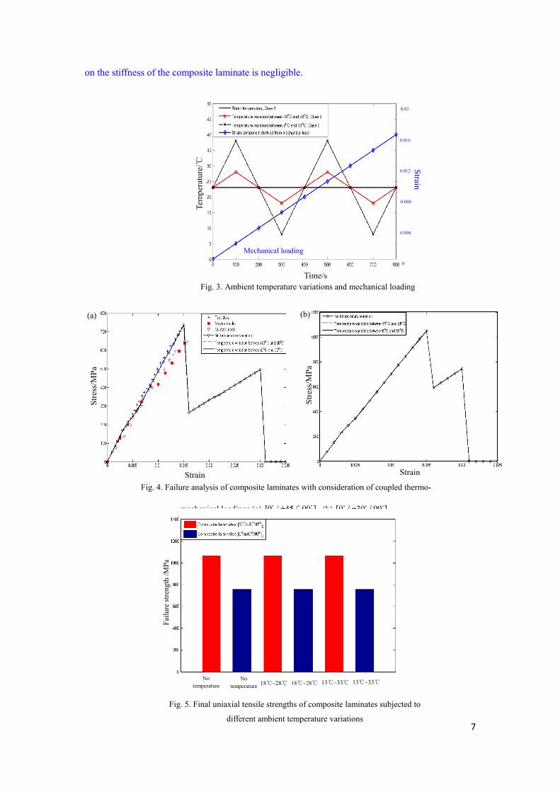
variation is coupled with the external loadings. Fig. 8 shows the stress distributions of 22σ in the
RVE at t =250s when it is subjected to longitudinal tension. From the figure it is clear to see that stress concentrations occur mostly around the interface. The maximum stress occurs in the vicinity of the interface, as shown in Figs. 8(a)-(c). It is interesting to mention that an increase of temperature variation tends to slightly decrease the maximum stress. In details, the sub-cell elements of the matrix have a maximum stress of 27.342MPa when there is no ambient temperature variation. However, as shown in Figs. 8 (b)-(c), the numerical results show that the maximum stresses in the matrix are 26.776 MPa and 23.718MPa, respectively, for the two cases with temperature variations. Similar conclusions for the locations of stress concentrations and maximum stresses can be made
when the microscopic stress fields of 22σ is calculated at t =125s, as shown Fig. 9. In addition, it
can be found that the transversal stress 22σ is symmetrical about both the horizontal and vertical axes under the uniaxial loading xxσ .
Figs. 10-11 present the shear stress 23σ distribution of the RVE at t=250s and t=125s. Similarly,
shear stress concentrations occur also at the interface. However, higher level of shear stresses can be found in both the matrix and the fiber, as shown in Fig. 10(a). Due to a lower failure strength of the matrix material compared with the fibers, it can be concluded that initial failure of the composites under uniaxial tension will occur in the matrix near the interface. Similar to the stress
(a) (b)
(c)
Fig. 8. Microscopic stress fields (MPa) at t =250s of the RVE under axial loading (a) No temperature variation (b) Temperature variation between 18℃ and 28℃ (c) Temperature variation between 8℃ and 38℃
Stress concentrations at the interface
(a) (b) (c)
Fig. 9. Microscopic stress fields (MPa) at t =125s of the RVE under axial loading (a) No temperature variation (b) Temperature variation between 18℃ and 28℃ (c) Temperature variation between 8℃ and 38℃

12
distribution of 22σ in the RVE, the maximum shear stress under axial loading xxσ tends to slightly decrease with a higher temperature fluctuation. Moreover, the shear stresses 23σ are symmetric about the two diagonals of the RVE under the uniaxial loading xxσ .
In order to further verify the conclusions made above, numerical results of the microscopic stress
fields of the RVE at t =250s under the transverse loading yyσ are also obtained and shown in Figs.
12-14. Clearly, the microscopic stress distributions depend closely on the ambient temperature, and stress concentrations are also located at the interface. It can be concluded that the initial failure will occur in the matrix due to its lower failure strength.
Fig. 11. Microscopic stress fields (MPa) at t =125s of the RVE under uniaxial loading (a) No temperature variation (b) Temperature variation between 18℃ and 28℃ (c) Temperature variation between 8℃ and 38℃
(b) (a) (c)
Fig. 10. Microscopic stress fields (MPa) at t =250s of the RVE under uniaxial loading (a) No temperature variation (b) Temperature variation between 18℃ and 28℃ (c) Temperature variation between 8℃ and 38℃
(a) (b) (c)
Stress concentrations at the interface
(a) (b) (c)
Maximum stress sub-cells
Fig. 12. Microscopic stress fields (MPa) at t =250s of the RVE under transversal loading (a) No temperature variation (b) Temperature variation between 18℃ and 28℃ (c) Temperature variation between 8℃ and 38℃

13
5.2. Biaxial loading
5.2.1. Failure envelopes of the UD lamina
Figures 15(a)-(c) present the biaxial failure envelopes in the stress plane, xx yyσ σ− when the
laminas are subjected to ambient temperature variations. Due to the symmetry, only the UD laminas
with 0o , 30o and 45o off-axis angles under the coupled thermo-mechanical loadings are considered.
It can be seen that all of the predicted failure envelopes are elliptical, and that the ambient temperature variations have affected the biaxial failure strength of the UD laminas, though the differences are small due to the fact that only small temperature alternations to room temperature
are considered. Fig.15(d) is the zoomed-in view of Fig15(c) to show the differences for the 45o UD
lamina. In principal, a higher temperature variation tends to decrease the biaxial failure strength.
(a) (b) (c)
Stress concentrations at the interface
Fig. 13. Microscopic stress fields (MPa) at t =250s of the RVE under transversal loading (a) No temperature
(a) (b) (c)
Stress concentrations at the interface
Fig. 14. Microscopic stress fields (MPa) at t =250s of the RVE under transversal loading (a) No temperature

14
5.2.2. Microscopic stress distributions
To study the biaxial failure mechanisms, the microscopic stress distributions in the RVE at
250st = are obtained when it is under a biaxial loading ratio of : 2 :1xx yyσ σ = . The transverse
stresses, 22σ and 33σ , as well as the shear stress, 23σ , are shown in Figs. 16-18. The numerical
results demonstrate that the microscopic stress distributions are temperature dependent, and a higher
temperature variation tends to increase the transversal maximum stresses 22σ and 33σ as shown in
Figs. 16-17. However, when the shear stress 23σ are considered as shown in Figs. 18(a)-(c), a higher
temperature variation tends to decrease the maximum shear stress. Similar to the uniaxial loading cases, for the composites under biaxial loading, stress concentrations are also near the interface.
(a) (b)
(c)
Fig. 15. Biaxial failure envelopes of the composite laminas with consideration of coupled thermo-mechanical loadings in the stress plane (a) (b) (c) (d) Local enlargement of the lamina
/Mpa
/MPa
/Mpa
/MPa
/Mpa
/MPa
(d)
/Mpa
/MPa

15
6. Conclusions
A multi-scale framework for investigating uniaxial and biaxial failure properties of composite structures subjected to coupled thermo-mechanical loading has been presented. Stiffness degradation and failure of laminas were studied by employing a micro scale representative volume element. At macro scale, the classic laminate theory was introduced to describe the thermo-mechanical failures of the composite laminates. By comparisons with the results from other researchers, it was found that the multiscale modelling framework was better placed for
Fig. 16. Microscopic stress fields (MPa) at t =250s of the RVE under biaxial loadings (a) No temperature variation (b) Temperature variation between 18℃ and 28℃ (c) Temperature variation between 8℃ and 38℃
(a) (b) (c)
Stress concentrations at the interface
Fig. 17. Microscopic stress fields (MPa) at t =250s of the RVE under biaxial loadings (a) No temperature
(b) (a) (c)
Stress concentrations at the interface
(b) (a) (c)
Fig. 18. Microscopic stress fields (MPa) at t =250s of the RVE under biaxial loadings (a) No temperature
Stress concentrations at the interface

16
investigating failure of composite laminates. Moreover, the numerical results indicated that the multi-scale model provided more insights to the second stage of loading. The effect of small temperature fluctuations on the stiffness of the composite laminates can be ignored.
The effect of temperature variations on the stress-strain relations was studied. The results shown that the 45。, 60。 and 90。 UD laminas exhibited a bilinear relation. For the temperature variations that were not too far from the room temperature, it appeared that its effect on the stiffness was more prominent than on the strength. The maximum stresses in the composites under both uniaxial tensile and biaxial loadings are always located in the vicinity of the interface, regardless of whether temperature variations were considered or not.
The studies reported in this paper provide some critical information for designing new composite structures subjected to small temperature variations. Evidently, interfacial design plays an important role to ensure better composite performance. In addition, it should be pointed out that this study is restricted to the failure analysis for both uniaxially and biaxially loaded laminates. In practical applications, a structural component may be restrained one way or another, which may generate significant shear and triaxial stresses.
Acknowledgments
This work was supported by the National Natural Science Foundation of China (Nos. 51675397,
51606137). The National Natural Science Foundation of Shaanxi Province (No. 2018JZ5005).
China Scholarship Council (No.201706965037). Fundamental Research Funds for the Central
Universities (Nos. JB180414, XJS18046). China Postdoctoral Science Foundation (No.
2016M600766). The 111 Project (No. B14042). The first author is also grateful to the Engineering
Department, Lancaster University for the support he has received during the course of his visit. Data Availability Statement The raw/processed data required to reproduce these findings cannot be shared at this time due to technical or time limitations. References [1] Yang ZB, Radzienski M, Kudela P, Ostachowicz W. Damage detection in beam-like composite structures
via Chebyshev pseudo spectral modal curvature. Compos Struct 2017; 168: 1-12.
[2] Cai H, Ye JJ, Wang YK, Jia F, Hong Y, Tian SH, Chen XF. Matrix failures effect on damage evolution of particle reinforced composites. Mech Adv Mater Struct 2019; DOI: 10.1080/15376494.2019.1579396.
[3] Ye JJ, Hong Y, Cai H, Wang YK Zhai Z, Shi BQ. A new three-dimensional parametric FVDAM for
investigating effective elastic moduli of particle-reinforced composites with interphase. Mech Adv Mater
Struc 2019; 26(22):1870-1880.
[4] Pan Z, Gu B, Sun B. Thermo-mechanical behaviors of 3-D braided composite material subject to high strain
rate compressions under different temperatures. Mech Compos Mater St 2016; 23(4):385-401.
[5] Jing Z, Yong HD, Zhou YH. Thermal coupling effect on the vortex dynamics of superconducting thin films:
time-dependent Ginzburg-Landau simulations. Super Cond Sci Tech 2018; 31(5): 1-10.
[6] Joshan YS, Neeraj G, Singh B N. A new non-polynomial four variable shear deformation theory in axiomatic
formulation for hygro-thermo-mechanical analysis of laminated composite plates. Compos Struct 2017; 182:
685-693.

17
[7] Kumaresan I, Pichaimani P, Ellappan S. Ceria doped mullite reinforced polybenzoxazine nanocomposites
with improved UV‐shielding and thermo‐mechanical properties. Polym Composite 2016; 39(6):2073-2080.
[8] Yang DH, Yang ZB, Zhai Z, Chen XF. Homogenization and localization of ratcheting behavior of composite
materials and structures with the thermal residual stress effect. Mater 2019; 12(3048):1-20.
[9] Hernandez MJ, White SE, Chessa JF, Ramana CV. Analytical and finite element analysis of thermal stresses
in TiN coatings. Mech Adv Mat Struct 2015; 22(12): 1024-1030.
[10] Hossain MM, Elahi AHMF, Afrin S, Mahmud M, Cho HM, Khan MA. Thermal Aging of Unsaturated
Polyester Composite Reinforced with E-Glass Nonwoven Mat. Autex Res J 2017; 17(4): 313-318.
[11] Tamboura S, Meftah H, Fitoussi J, Bendaly H, Tcharkhtchi A. Thermal aging kinetic and effects on
mechanical behavior of fully recycled composite based on polypropylene/polyethylene blend. J Appl Polym
Sci, 2018; 135(33): 1-10.
[12] Ndiaye EB, Duflo H, Maréchal P. Thermal aging characterization of composite plates and honeycomb
sandwiches by electromechanical measurement. J Acoust Soc Am 2017; 142(6):3691-3702.
[13] Yang J, Wang L, Tan X. Effect of Sintering Temperature on the Thermal Expansion Behavior of ZrMgMo3
O12p /2024Al Composite. Ceram Int 2018; 44(9): 10744-10752. [14] Sharma N K, Misra R K, Sharma S. Modeling of thermal expansion behavior of densely packed Al/SiC
composites. Int J Solids Struct 2016; 102-103:77-88.
[15] Li DS, Duan HW, Wang W. Strain rate and temperature effect on mechanical properties and failure of 3D
needle-punched Carbon/Carbon composites under dynamic loading. Compos Struct 2017; 172: 229-241.
[16] Yang B, Yue Z, Geng X, Geng X, Wang P. Temperature effects on transverse failure modes of carbon
fiber/bismaleimides composites. J Compos Mater 2016; 51(2): 1-12.
[17] Hu C, Liao XW, Qin QH, Wang G. The fabrication and characterization of high density polyethylene
composites reinforced by carbon nanotube coated carbon fibers. Compos Part A-Appls 2019; 121: 149-156.
[18] Benelfellah A, Halm D, Bertheau D, Boulet P, Acem Z, Brissinger D, Rogaume T. Effect of a coupled
thermomechanical loading on the residual mechanical strength and on the surface temperature of wound
carbon/epoxy composite. J Compos Mater 2017; 51(22):3137-3147.
[19] Sun Z, Niu X, Huang S. A unified macro- and micromechanics constitutive model of fully coupled fields.
Mech Compos Mater 2014; 50(2):233-244.
[20] Farzad E, Navid F. Thermo-mechanical vibration analysis of sandwich beams with functionally graded
carbon nanotube-reinforced composite face sheets based on a higher-order shear deformation beam theory.
Mech Adv Mater Struc 2017; 24(10): 820-829.
[21] Ahmadi I. Micromechanical failure analysis of composite materials subjected to biaxial and off-axis loading.
Struct Eng Mech 2017; 62(1): 43-54.
[22] Leclerc W, Haddad H, Guessasma M. On a discrete element method to simulate thermal-induced damage in
2D composite materials. Comput Struct 2018; 196: 277-291.
[23] Liu S, Shi B, Siddique A. Numerical analyses on thermal stress distribution induced from impact
compression in 3D carbon fiber/epoxy braided composite materials. J Therm Stresses 2018; 41(7):1-17.
[24] Zhang DX, Ye JQ, Lam D. Ply cracking and stiffness degradation in cross-ply laminates under biaxial
extension, bending and thermal loading. Compos Struct 2006; 75: 121-131.
[25] Zhang DX, Ye JQ. Free-edge and ply cracking effect in cross-ply laminated composites under uniform
extension and thermal loading. Compos Struct 2006; 76: 314-325.
[26] Yang D, Sheng Y, Ye JJ, Tan Y. Multi-scale modeling of the progressive damage in cross-ply laminates
under thermal and mechanical loading. IOP Conf. Ser.: Mater. Sci. Eng. 40: 012029.
[27] Bhattacharjee S, Bajwa D S. Degradation in the mechanical and thermo-mechanical properties of natural

18
fiber filled polymer composites due to recycling. Constr Build Mater 2018; 172:1-9.
[28] Boccardi S, Carlomagno G M, Meola C. Evaluation of polypropylene based composites from thermal effects
developing under cyclic bending tests. Compos Struct 2017;182: 628-635.
[29] Boccardi S, Carlomagno G M, Meola C. Visualization of Thermal Effects in Polypropylene-based
Composites under Cyclic Bending Tests. Procedia Eng 2016; 167: 270-275.
[30] Gopinath G, Batra RC. A common framework for three micromechanics approaches to analyze elasto-
plastic deformations of fiber-reinforced composites. Int J Mech Sci 2018; 148: 540-553.
[31] Shi PP. Singular integral equation method for 2D fracture analysis of orthotropic solids containing doubly
periodic strip-like cracks on rectangular lattice arrays under longitudinal shear loading. Appl Math Model.
2020; 77: 1460-1473. [32] Eyass Massarwa, Jacob Aboudi, Rami Haj-Ali. A multiscale progressive damage analysis for laminated
composite structures using the parametric HFGMC micromechanics. Compos Struct 2018; 188(15): 159-
172.
[33] Aboudi J. The effect of anisotropic damage evolution on the behavior of ductile and brittle matrix
composites. Int J Solids Struct 2011; 48(14): 2102-2119.
[34] Ye JJ, Chu CC, Cai H, Wang YK, Qiao XJ, Zhai Z, Chen XF. A multi-scale modeling scheme for damage
analysis of composite structures based on the High-Fidelity Generalized Method of Cells. Compos Struct
2018; 206: 42-53.
[35] Aboudi J. Thermomechanically coupled micromechanical analysis of multiphase composites. J Eng Math
2008; 61(2-4):111-132.
[36] Ye JJ, Hong Y, Wang YK, Shi BQ, Zhai Z, Chen XF. Thermal cycling influences on compressive
deformations of laminate composites. Polym Composite. 2019; 40(7): 2908-2918.
[37] Aboudi J, Arnold SM, Bednarcyk BA. The generalized method of cells micromechanics. Micromechanics
of Composite Materials-A Generalized Multiscale Analysis Approach. Oxford, Kidlington (2013).
[38] Aboudi J, Pindera MJ, Arnold SM. High-Fidelity Generalized Method of Cells for Inelastic Periodic
Multiphase Materials, NASA Contractor Report, TM-2002-211469 (2002).
[39] Wang YX. Mechanics and structural design of composite materials. Shanghai: East China university of
science and technology Press; 2012.
[40] Belingardi G, Mehdipour H, Mangino E, Martorana B. Progressive damage analysis of a rate-dependent
hybrid composite beam. Compos Struct 2016; 154(15): 433-442.
[41] Zhao Lin. Strength prediction of composite based on unit cell analytic model and progressive damage
analysis, Harbin Institute of Technology (2012).
[42] Ye JJ, Chu CC, Cai H, Hou XN, Shi BQ, Tian SH, Chen XF, Ye JQ: A multi-scale model for studying failure
mechanisms of composite wind turbine blades. Compos Struct 2019, 212: 220-229.
[43] Mayes SJ, Hansen AC. Composite laminate failure analysis using multi continuum theory. Compos Sci
Techno 2004; 64: 379-394
[44] Cuntze RG, Freund A, The predictive capability of Failure Mode Concept-based strength criteria for
multidirectional laminates. Compos Sci Technol 2004; 64: 343-377. [45] Hinton MJ, AS Kaddour, PD Soden. Failure Criteria in Fibre-Reinforced-Polymer Composites: The World-
Wide Failure Exercise. Publisher: Elsevier (2004).


![Composites] Fiberglass Reinforced Plastics](https://static.fdocuments.net/doc/165x107/54357942219acdd95f8b47ae/composites-fiberglass-reinforced-plastics.jpg)