Fahrenheat FZL Large Wall Heater.ppt [Compat
14
Fahrenheat FZL Large Wall Heater • The following pictorial is a step by step installation guide. It will show the installation in a new construction situation, but the basic steps are the same for existing construction. Read the owners manual for the installation that matches your specific needs Example
Transcript of Fahrenheat FZL Large Wall Heater.ppt [Compat
Fahrenheat FZL Large Wall Heater
• The following pictorial is astep by step installationguide. It will show theinstallation in a newconstruction situation, butthe basic steps are thesame for existingconstruction. Read theowners manual for theinstallation that matchesyour specific needs
Example
WARNING• Before installing this electric heater
read and understand the instructionmanual.
• For Wall Mounting Only
• The following minimum clearances mustbe maintained:– Heater to floor – 8 in. (203mm)
– Heater to adjacent wall – 8 in. (203mm)
– Heater to ceiling – 36 in. (915mm)
Installation Instructions
• Verify the Nameplate rated VOLTAGE &ERAGE prior to installation.
• Size the wire and breaker for the amp loadof the heater
• If not familiar with electrical circuits,contact a licensed electrician.
Step 1
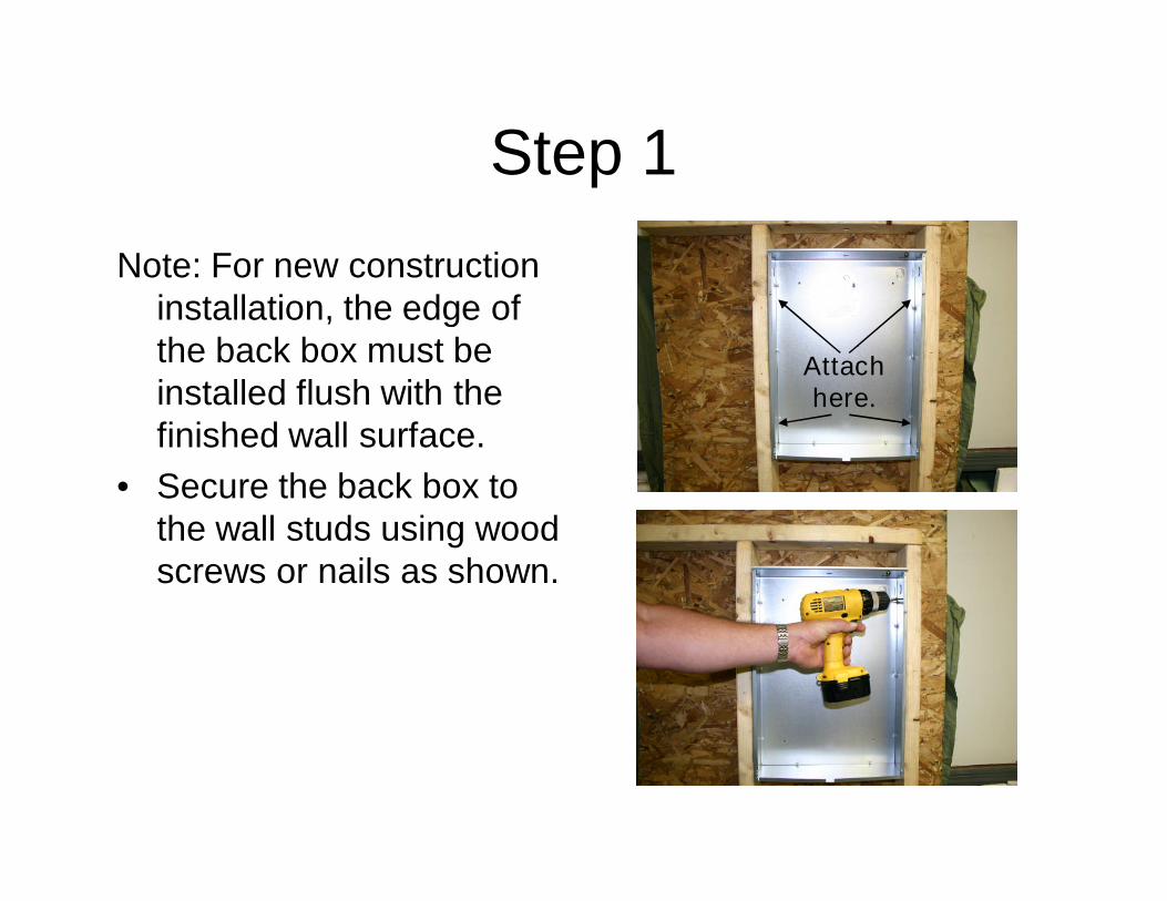
Note: For new constructioninstallation, the edge ofthe back box must beinstalled flush with thefinished wall surface.
• Secure the back box tothe wall studs using woodscrews or nails as shown.
Attachhere.
Step 2
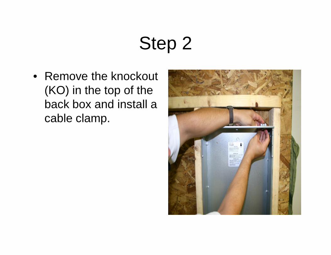
• Remove the knockout(KO) in the top of theback box and install acable clamp.
Step 3
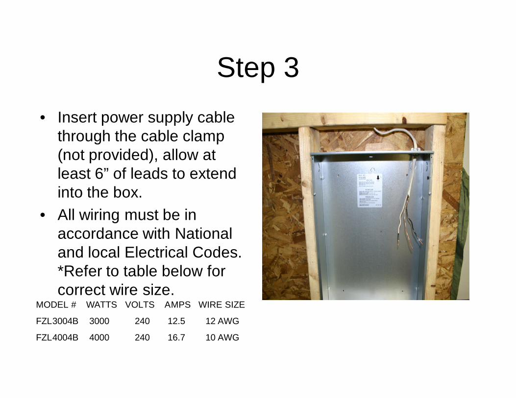
• Insert power supply cablethrough the cable clamp(not provided), allow atleast 6” of leads to extendinto the box.
• All wiring must be inaccordance with Nationaland local Electrical Codes.*Refer to table below forcorrect wire size.
MODEL # WATTS VOLTS AMPS WIRE SIZE
FZL3004B 3000 240 12.5 12 AWG
FZL4004B 4000 240 16.7 10 AWG
Step 4
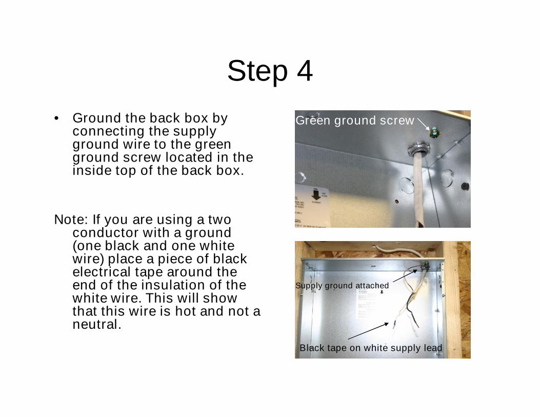
• Ground the back box byconnecting the supplyground wire to the greenground screw located in theinside top of the back box.
Note: If you are using a twoconductor with a ground(one black and one whitewire) place a piece of blackelectrical tape around theend of the insulation of thewhite wire. This will showthat this wire is hot and not aneutral.
Green ground screw
Supply ground attached
Black tape on white supply lead

Step 5
• Locate the 4 screws onthe front of the back boxand loosen as necessary.
• The heater assembly willslide over these 4 screwsinto key hole slots.
• Tighten 4 screws tosecurely fasten the heaterassembly to the backbox.
• Note: Do not install theheater into back box untilthe finished wall iscomplete.
Step 6
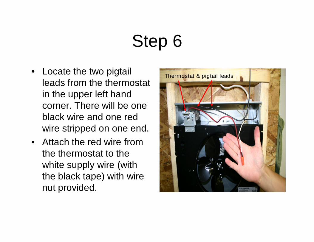
• Locate the two pigtailleads from the thermostatin the upper left handcorner. There will be oneblack wire and one redwire stripped on one end.
• Attach the red wire fromthe thermostat to thewhite supply wire (withthe black tape) with wirenut provided.
Thermostat & pigtail leads
Step 7
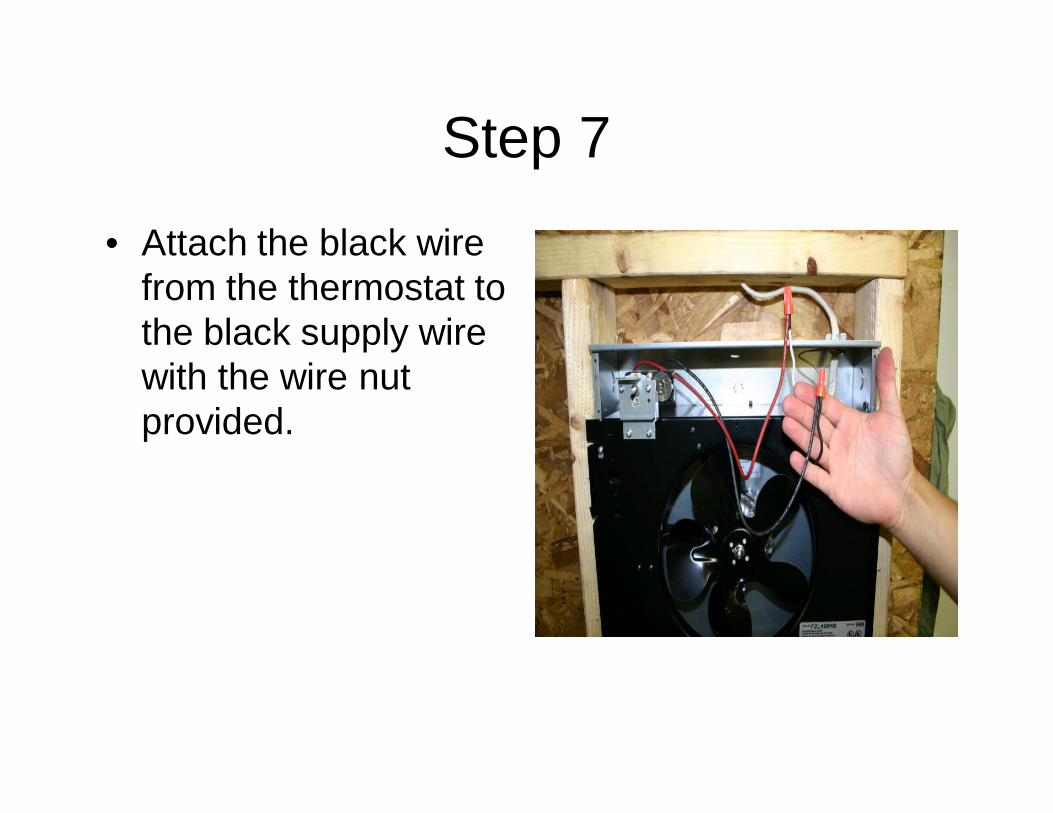
• Attach the black wirefrom the thermostat tothe black supply wirewith the wire nutprovided.
Step 8
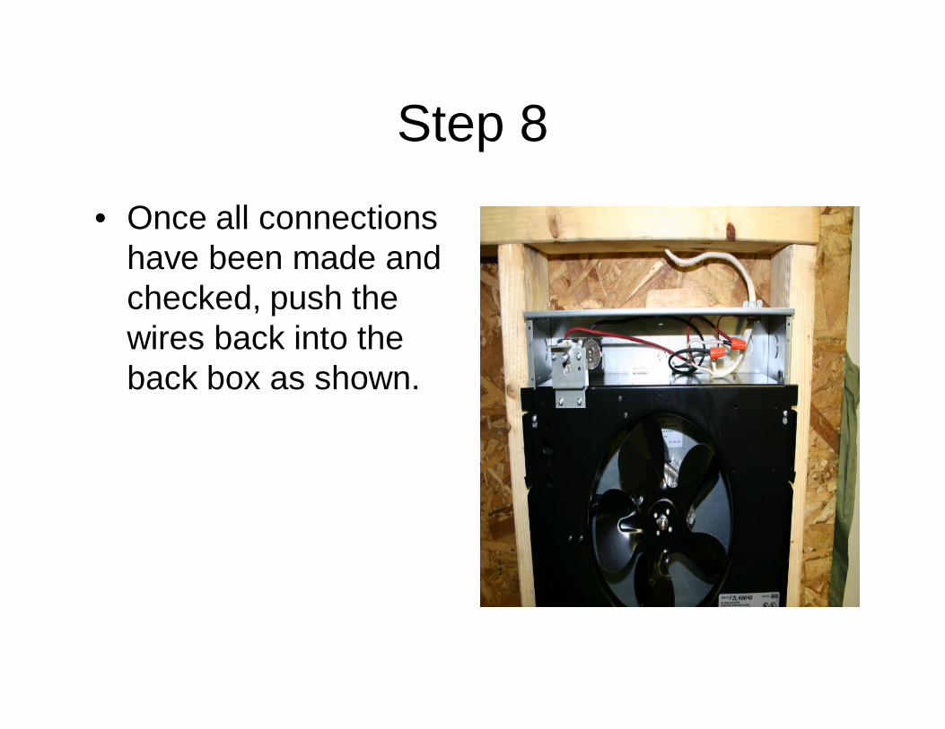
• Once all connectionshave been made andchecked, push thewires back into theback box as shown.
Step 9
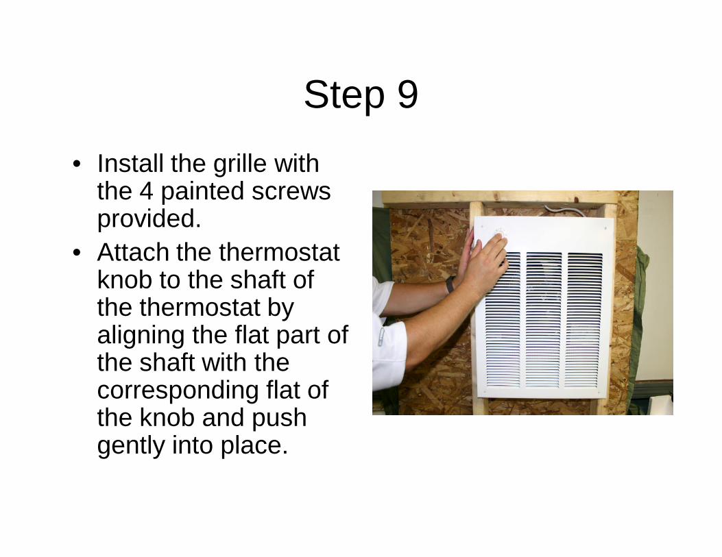
• Install the grille withthe 4 painted screwsprovided.
• Attach the thermostatknob to the shaft ofthe thermostat byaligning the flat part ofthe shaft with thecorresponding flat ofthe knob and pushgently into place.
Operation Check
• Turn the thermostat knob to the full counterclockwise position. (off).• Turn the power on at the main disconnect.• Let the unit sit for 5 minutes to make sure nothing is operating.• Turn the knob to the full clockwise position.• In a matter of a few seconds you will feel heat coming from the unit.
The fan will delay on approximately 45 seconds.• Once the unit has been energized approximately 45 seconds the
fan will start and blow heat into the room. (Note: you may notice aslight amount of smoke from the unit at this point. It is normal andcomes from a light coating of oil on the elements.)
• Allow the unit to run for a few minutes and then turn the thermostatdown, slowly (counterclockwise) until you hear a click. Stop turningthe knob at this point and allow the unit to operate.
• The heater should run a minute or two and then shut off.• If all the above worked properly you have completed the installation
of the heater.
Heater Operation
• The built in thermostat in this heater is known asa comfort thermostat. It has a range of 45 – 85degrees F.
• To set the thermostat, turn the knob to its fullclockwise position (on) and allow the unit tooperate until the room reaches a comfortabletemperature.
• Turn the knob counterclockwise, slowly until youhear (or feel) a click.
• Stop at that position and allow the unit to run. Itwill cycle on and off as needed to maintain thattemperature in the room.