FAG SPECIAL SPHERICAL ROLLER BEARINGS FOR ...¡logo-Máquinas...FAG Spherical Roller Bearings for...
26
FAG OEM und Handel AG FAG SPECIAL SPHERICAL ROLLER BEARINGS FOR VIBRATING MACHINES
-
Upload
truongdang -
Category
Documents
-
view
220 -
download
1
Transcript of FAG SPECIAL SPHERICAL ROLLER BEARINGS FOR ...¡logo-Máquinas...FAG Spherical Roller Bearings for...
FAG OEM und Handel AG
FAG SPECIAL SPHERICAL ROLLER BEARINGSFOR VIBRATING MACHINES

FAG Special Spherical Roller Bearingsfor Vibrating Machines
Publ. No. WL 21 100/3 EA
FAG OEM und Handel AG A company of the FAG Kugelfischer Group
Postfach 1260 · D-97419 SchweinfurtTelephone (0 97 21) 91 38 83 · Telefax (0 97 21) 91 39 58www.fag.de

Contents
1 FAG Spherical Roller Bearings for Vibratory Stressing . . . . . . . . . . . . . . . . . . . . . . . . . . . . . . . . . . . . 3
1.1 Operating conditions for bearings in vibrating machines . . . . . . . . . . . . . . . . . . . . . . . . . . . . . . . . . . . 3
1.2 Bearing series and basic designs . . . . . . . . . . . . . . . . . . 31.2.1 Spherical roller bearings of series 223E . . . . . . . . . . . . 31.2.2 Spherical roller bearings of series 223A . . . . . . . . . . . . 41.2.3 Spherical roller bearings of series 233A . . . . . . . . . . . . 41.3 Bearings with a tapered bore . . . . . . . . . . . . . . . . . . . . 41.4 Bearings with a chromium-plated bore . . . . . . . . . . . . 41.5 Specification T41A . . . . . . . . . . . . . . . . . . . . . . . . . . . . 41.5.1 Tolerances of bearing bore and outside diameter . . . . . 41.5.2 Radial clearance groups, radial clearance reduction
in bearings with a tapered bore . . . . . . . . . . . . . . . . . . . 51.6 Attainable radial acceleration . . . . . . . . . . . . . . . . . . . . 61.7 Heat treatment . . . . . . . . . . . . . . . . . . . . . . . . . . . . . . . 6
2 Dimensioning of the Bearings . . . . . . . . . . . . . . . . . . 6
2.1 Two bearing screen with circle throw . . . . . . . . . . . . . . 62.2 Two bearing screen with straight-line motion . . . . . . . 82.3 Four bearing screen . . . . . . . . . . . . . . . . . . . . . . . . . . 102.4 Centrifugal force nomogram . . . . . . . . . . . . . . . . . . . 112.5 Load rating nomogram . . . . . . . . . . . . . . . . . . . . . . . . 12
3 Design Characteristics . . . . . . . . . . . . . . . . . . . . . . . . 13
3.1 Two bearing screen with circle throw (grease lubrication) . . . . . . . . . . . . . . . . . . . . . . . . . . . 13
3.2 Two bearing screen with circle throw (oil sump lubrication) . . . . . . . . . . . . . . . . . . . . . . . . .14
3.3 Two bearing screen with circle throw (oil circulation lubrication) . . . . . . . . . . . . . . . . . . . . 15
3.4 Two bearing screen withstraight-line motion (oil splash lubrication) . . . . . . . 16
3.5 Four bearing screen (grease lubrication) . . . . . . . . . . 17
4 Lubrication . . . . . . . . . . . . . . . . . . . . . . . . . . . . . . . . . 18
4.1 Grease lubrication . . . . . . . . . . . . . . . . . . . . . . . . . . . 184.2 Oil lubrication . . . . . . . . . . . . . . . . . . . . . . . . . . . . . . 194.2.1 Oil sump lubrication . . . . . . . . . . . . . . . . . . . . . . . . . 194.2.2 Oil circulation lubrication . . . . . . . . . . . . . . . . . . . . . 214.3 Recommended lubricants . . . . . . . . . . . . . . . . . . . . . . 22
5 Dimensional Tables of FAG Special Spherical Roller Bearings for Vibrating Machines . . . . . . . . . . 23
5.1 Series 223E.T41A . . . . . . . . . . . . . . . . . . . . . . . . . . . 235.2 Series 223A.MA.T41A . . . . . . . . . . . . . . . . . . . . . . . . 245.3 Series 233A(S).MA.T41A . . . . . . . . . . . . . . . . . . . . . 24
FAG 2

FAG Spherical Roller Bearings for Vibratory StressingOperating conditions · Bearing series and basic designs
1 FAG Spherical Roller Bearings forVibratory Stressing
1.1 Operating conditions for bearings in vibrating machines
Vibrating screens, which are used forgrading material, and other machineswhere vibratory stressing has to be ac-commodated, such as road rollers and sawframes, are among the most severe bear-ing mountings encountered in machineryconstruction.
The rolling bearings in the exciter-unitdrives of these machines have to accom-modate high loads, high speeds, acceler-ations and centrifugal forces. Often, ad-verse environmental conditions such asdirt and moisture have to be accommo-dated as well.
The special spherical roller bearingsdeveloped by FAG are designed for theoperating conditions in vibrating ma-chines and have proven their worth infield application.
Especially the cages of the rolling bear-ings are stressed by high radial accelera-tions. Under unfavourable conditions,axial accelerations may have to be accom-modated as well.
The rotating imbalance generates a re-volving shaft deflection and additionalsliding motions within the bearings. As aresult, the friction, and consequently theoperating temperature of the bearings, in-crease. The special spherical roller bear-ings can compensate for the usual mis-alignments between inner ring and outerring up to 0.15°. Where greater misalign-ments have to be accommodated, FAGApplication Engineering should be con-sulted.
1.2 Bearing series and basic designs
The main dimensions of the FAG spe-cial spherical roller bearings for vibratingmachines correspond to the dimensionalseries 23 and 33 (E DIN 616: 1995-01,ISO 15).
To accommodate the specific operat-ing conditions found in vibrating ma-chines FAG manufacture all the specialspherical roller bearings described in thispublication in accordance with specifica-tion T41A, see also section 1.5.
The highest load carrying capacity dueto an optimized cross section utilization isprovided by the advanced spherical rollerbearings of series 223E. The bearings de-signed to accommodate vibratory stress-ing are available with bore diameters ofup to 150 mm. They have outer ring riding, surface-hardened pressed steelwindow-type cages with a good form rigidity.
FAG bearings of dimensional series223 with bore diameters of more than150 mm are available as design A. The inner ring has three fixed lips. Two outerring riding machined brass cage halves radially support the forces of gravity to-ward the outside.
Wider bearings of series 233A have asimilar internal design as the bearings ofseries 223A. These bearings are used forapplications where an extremely highload carrying capacity is required.
1.2.1 Spherical roller bearings of series 223E
E-design FAG spherical roller bearingshave no centre lip on their inner ring andexcel by an extremely high load carryingcapacity. This advantage is also offered by
the FAG special bearings for vibratorystressing of design 223E.T41A, fig. 1.
3 FAG
This is the new FAG standard designfor bearings with bore diameters of 40 to 150 mm (bore reference numbers 08to 30).
After extensive testing both on the testrig and in the field, the bearings of design223E.T41A have proved to be extremelysuitable for numerous field applications.
In the bearing, every roller row has itsown outer ring riding window-type pressed steel cage half.
The cage halves are supported by thecage guiding ring in the outer ring. De-pending on the bearing size, either a splitor an unsplit guiding ring is used. Allcage components have hardened surfaces.
1: New design 223E.T41A of special spherical roller bearings for vibrating machines (bore reference numbers 08 to 30)

FAG Spherical Roller Bearings for Vibratory StressingBearing series and basic designs · Bearings with a tapered bore · Bearings with a chromium-plated bore · Specification T41A
1.2.2 Spherical roller bearings ofseries 223A
Where bore diameters of 160 mm andmore are required (bore reference number�32), FAG recommends to use its field-proven special spherical roller bearings ofdesign 223A.MA.T41A, fig. 2.
The bearings have a fixed centre lip onthe inner ring and two lateral retaininglips. The two-piece machined brass cage(suffix MA) is of the outer ring ridingtype.
1.2.3 Spherical roller bearings of series 233A
For applications where the highestpossible load carrying capacity is requiredin vibrating machines, special sphericalroller bearings of series 233A(S).MA.T41Awith bearing bores ranging from 100 to200 mm (bore reference numbers 20 to40) are available.
These bearings have three fixed lips onthe inner ring. The split machined brasscage (suffix MA) is guided in the outerring.
1.3 Bearings with a tapered bore
Special spherical roller bearings for vibrating machines usually have a cylin-drical bore. For special applications, e.g.saw frames, bearings with a tapered bore(taper 1:12) are also available. These de-signs are suffixed EK.T41A orAK.MA.T41A.
1.4 Bearings with a chromium-plated bore
In order to reduce or prevent frettingcorrosion between the bearing bore andthe shaft, FAG supplies spherical rollerbearings with a thin-layer chromium-plated bore to order. They ensure that thedisplaceability (floating bearing function)between bearing bore and shaft, which isnecessary due to thermal influences, willbe maintained for a long period of opera-tion.
The bearings with a chromium-platedbore have the same dimensions and toler-ances as the FAG standard bearings for
vibrating machines and are interchange-able with them.
The thin-layer chromium plating canbe ordered indicating the suffix J24BA.
Order designation (example):22324E.J24BA.T41A
1.5 Specification T41A
The FAG spherical roller bearings forvibrating machines are produced in ac-cordance with specification T41A. It takes into account the specific require-ments of this application. In this specifi-cation the tolerances and the radial clear-ance of the special spherical roller bear-ings are defined.
1.5.1 Tolerances of bearing bore andoutside diameter
The specification T41A prescribes arestriction of the bore tolerance to the upper half of the normal tolerance field.The outside diameter must be in the cen-tre half of the normal tolerance field. Inbearings with a tapered bore, only theoutside diameter tolerances are in the re-duced tolerance range. For the tolerancevalues, see table, fig. 3.
In this way, with the shaft tolerancesg6 or f6, the sliding fit required for theinner ring, and with the housing toler-ance P6 the interference fit required forthe outer ring are safely achieved. The inner ring is not subjected to a pure pointload, and the outer ring is subjected tocircumferential loads.
The other tolerances correspond to thetolerance class PN according to DIN620.
FAG 4
2: Design 223A.MA.T41A of the specialspherical roller bearings for vibrating machines (bore reference number �32)

FAG Spherical Roller Bearings for Vibratory StressingSpecification T41A
1.5.2 Radial clearance groups, radial clearance reduction in bearings with a tapered bore
The specification T41A defines C4 asthe standard clearance group for allspherical roller bearings in vibrating screen design, so that it must not be indi-cated specifically any longer. In this way adetrimental radial preloading of the bear-ings in the event of unfavourable combi-nations of various influences such as fits,deformations etc. is safely prevented. Thisapplies especially to the startup and run-in periods when the temperature gradientbetween inner ring and outer ring is par-ticularly high.
Only in rare cases, e.g. if the screenedmaterial is hot, or if the bearing locationis exposed to extremely high externalheating, a different radial clearance mustbe considered for the spherical rollerbearings in vibrating machines.
For special applications, e. g. saw frames, bearings with a bearing clearanceother than C4 may be required. In suchcases, the suffix for the clearance, e.g. C3,has to be indicated uncoded. FAG bear-ings of this design are available on re-quest. Radial clearance values for the spe-cial spherical roller bearings are indicatedin the table, fig. 4.
Bearings with a tapered bore are usual-ly mounted onto a tapered shaft seat. Theradial clearance reduction during mount-ing (see table, fig. 5) can serve as a yard-stick for the fit between inner ring andshaft.
5 FAG
3: Reduced tolerance according to FAG specification T41A
Inner ringDimensions in mm
Nominal bearing over 30 50 80 120 180 250bore to 50 80 120 180 250 315
Tolerances in µm
Deviation ∆dmp 0 0 0 0 0 0–7 –9 –12 –15 –18 –21
Outer ringDimensions in mm
Nominal over 80 150 180 315 400 500O.D. to 150 180 315 400 500 630
Tolerances in µm
Deviation ∆Dmp –5 –5 –10 –13 –13 –15–13 –18 –23 –28 –30 –35
4: Radial clearance of the FAG spherical roller bearings
Dimensions in mm
Nominal over 30 40 50 65 80 100 120 140 160 180 200 225 250 280bearing bore to 40 50 65 80 100 120 140 160 180 200 225 250 280 315
with cylindrical bore
Bearing clearance in µm
Clearance min 45 55 65 80 100 120 145 170 180 200 220 240 260 280group C3 max 60 75 90 110 135 160 190 220 240 260 290 320 350 370
Clearance min 60 75 90 110 135 160 190 220 240 260 290 320 350 370group C4 max 80 100 120 145 180 210 240 280 310 340 380 420 460 500
with tapered bore
Bearing clearance in µm
Clearance min 50 60 75 95 110 135 160 180 200 220 250 270 300 330group C3 max 65 80 95 120 140 170 200 230 260 290 320 350 390 430
Clearance min 65 80 95 120 140 170 200 230 260 290 320 350 390 430group C4 max 85 100 120 150 180 220 260 300 340 370 410 450 490 540
5: Radial clearance reduction in spherical roller bearings with a tapered bore (solid shaft)
Nominal bearing Reduction of the Axial displacement Check values for thebore bearing clearance on taper 1:12 smallest radial clear-
ance after mountingd Shaft Sleeve CN C3 C4over to min max min max min max min min minmm mm mm mm
30 40 0.02 0.025 0.35 0.4 0.35 0.45 0.015 0.025 0.0440 50 0.025 0.03 0.4 0.45 0.45 0.5 0.02 0.03 0.0550 65 0.03 0.04 0.45 0.6 0.5 0.7 0.025 0.035 0.05565 80 0.04 0.05 0.6 0.75 0.7 0.85 0.025 0.04 0.0780 100 0.045 0.06 0.7 0.9 0.75 1 0.035 0.05 0.08
100 120 0.05 0.07 0.7 1.1 0.8 1.2 0.05 0.065 0.1120 140 0.065 0.09 1.1 1.4 1.2 1.5 0.055 0.08 0.11140 160 0.075 0.1 1.2 1.6 1.3 1.7 0.055 0.09 0.13160 180 0.08 0.11 1.3 1.7 1.4 1.9 0.06 0.1 0.15180 200 0.09 0.13 1.4 2 1.5 2.2 0.07 0.1 0.16
200 225 0.1 0.14 1.6 2.2 1.7 2.4 0.08 0.12 0.18225 250 0.11 0.15 1.7 2.4 1.8 2.6 0.09 0.13 0.2250 280 0.12 0.17 1.9 2.6 2 2.9 0.1 0.14 0.22280 315 0.13 0.19 2 3 2.2 3.2 0.11 0.15 0.24

FAG Spherical Roller Bearings for Vibratory StressingDimensioning of the Bearings
1.6 Attainable radial acceleration
As the centrifugal forces toward theouter ring are radially supported the spe-cial spherical roller bearings in vibratingmachines can accommodate high acceler-ations, see diagram below.
Attainable radial acceleration values forthe special spherical roller bearings forvibrating machines
a) n · dm = 350 000 min–1 · mm maximum attainable values under optimum mounting conditions and oillubrication, e.g. planetary gears
b) n · dm = 140 000 min–1 · mm usual operating conditions for saw frames with grease lubrication
c) n · dm = 230 000 up to 300 000 min–1 · mm usual application for vibrating screenswith grease or oil lubrication
2 Dimensioning of the bearings
Bearing arrangements which are com-parable with field-proven arrangementscan be dimensioned on the basis of theindex of dynamic stressing fL, providedthat the boundary conditions are com-parable as well. Usually, vibrating screenbearings are designed for fL values be-tween 2.5 and 3.
fL = (C/P) · fn
C dynamic load rating [kN], see bearingtables, section 5
P equivalent dynamic load [kN], see sections 2.1 to 2.3
fn speed factor, see catalogue WL 41 520
When determining the equivalent dy-namic load P of the spherical roller bear-ings for applications involving vibratorystressing those influences which cannotbe defined precisely are taken into account by a safety factor of fz = 1.2 withwhich the radial bearing load Fr is multi-plied. Experience shows that sufficientlylong operating periods are thus achieved.
2.1 Two bearing screen with circle throw
Fig. 6 shows the principle of an imbal-ance-type two bearing screen.
The bearing load imposed by the cen-trifugal force of the screen box constitut-ed by the screen box weight, the vibrationradius and the speed is obtained using thefollowing equation:
Fr = 1 · m · r · �2 =z 103
= 1 · G · r ( π · n )2[kN] (1)
z g 30
Fr radial bearing load [kN]
m screen box mass [kg]
r vibration radius [m]
� angular velocity [1/s]
G screen box weight [kN]
g acceleration due to gravity [m/s2]
n speed [min–1]
z number of bearings
The vibration radius r of two bearingscreens can be calculated from the ratio ofthe screen box weight to the imbalanceweight. Since two bearing screens gener-ally work far beyond the critical range approaching the operational amplitudethe common centroidal axis of the twomasses (screen box and imbalance mass)can be assumed to persevere during rota-tion, fig. 7.
Hence
G · r = G1 (R – r)
and the vibration radius
r = G1 · R [m] (2)G + G1
where
G weight of screen box [kN]
G1 imbalance weight [kN]
R distance between the centre of gravity of imbalance and the bearing axis [m]
r vibration radius of the screen box [m]
G1 · R imbalance moment of the exciter unit [kN m]
G + G1 total weight supported by springs [kN]
Introducing equation (2) into equa-tion (1) and transforming the expression,the radial bearing load
Fr = 1 · G1 · R · ( π · n )2[kN] (3)
z g 1 + G1 30G
FAG 6
50 100 20070Bearing bore
a)
b)
c)
5
10
20
50
100
200
300
Acc
eler
atio
n
150mm
g
1.7 Heat treatment
All FAG spherical roller bearings of series 223 and 233 for vibratory stressingcan be used at operating temperatures ofup to 200 °C. This temperature limit alsoapplies to the metal cages in the bearings.

Dimensioning of the BearingsTwo bearing screen with circle throw
Example
Screen box weight G = 35 kNVibration radius r = 0.003 mSpeed n = 1200 min–1
Number of bearings z = 2
Bearing load according to equation (1)
Fr = 1 · 35 · 0.003 ( π · 1200 )2=
2 9.81 30
= 84.5 [kN]
The equivalent dynamic bearing loadneeded to determine the required dynam-ic load rating of the bearing
P = 1.2 · Fr = 1.2 · 84.5 = 101 [kN]
7 FAG
6: Principle of a two bearing screen with circle throw
Rr
G1
G
7: The vibration radius is a function of the screen box weight and the imbalance weight
R
rR-r
G1
G

Dimensioning of the BearingsTwo bearing screen with straight-line motion
2.2 Two bearing screen with straight-line motion
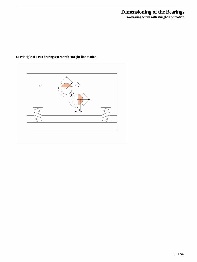
Basically, the exciter unit of a twobearing screen with straight-line motionconsists of two contra-rotating synchro-nous circular throw systems, fig. 8.
The forces involved are determined byresolving the rotating centrifugal forcevectors of the imbalance shafts into twocomponents: one in the direction of theline connecting the two shafts and theother perpendicular to this line. It can bereadily seen that the components lying inthe direction of the shaft connecting linein overall effect cancel each other out,whereas the perpendicular componentsadd up, generating a harmonic pulsatinginertia force. This force is responsible forthe straight line motions of the screenbox.
Since, in the direction of vibration, theovercritical operation enables the so-called static amplitude to be reached andthe common centroidal axis of the screenbox and the imbalance masses does notvary during vibration the bearing loadsare as follows:
In the direction of vibration
Fr min = 1 · m · r · �2 =z 103
= 1 · G · r · ( π · n )2=
z g 30
= 1 · G1 · (R – r) · ( π · n )2[kN] (4)
z g 30
wherer [m] amplitude of the linear vibrationR [m] distance between the centres
of gravity of imbalance and thepertinent bearing axes
Perpendicular to the direction ofvibration
Fr max = 1 · G1 · R · ( π · n )2[kN] (5)
z g 30
meaning that the bearing load is slightlyhigher.
Contrary to a circle throw screen witha constant bearing load, the bearing loadson a straight-line motion screen vary twice between Fr max and Fr minduring onerevolution of the eccentric drive shafts
Comparing equation (4) with equa-tion (1) shows that the minimum bearingload accommodated by a straight-linemotion screen is exactly the same as thatof a circle throw screen.
For a straight-line screen whose load-ing varies according to a sinusoidal pat-tern the bearing load can be calculatedusing the formula
Fr = 0.68 · Fr max + 0.32 · Fr min [kN]
With a circle throw screen, the bearingload can be determined from the screenbox weight G, the vibration radius r andthe speed n. With a straight-line screen,these data merely allow the minimumload to be determined. An accurate cal-culation is only possible if either the im-balance weight G1 or the distance R be-tween the centres of gravity of imbalanceand their pertinent bearing axes are known as well. The unknown quantitycan then be determined from
G · r = G1 (R – r) [kN m]
Example
Screen box weight G = 33 kN
Imbalance weight G1 = 7.5 kN
Amplitude r = 0.008 m
Speed n = 900 min–1
Number of bearings z = 4
With R = r (G + G1) =G1
= 0.008 (33 + 7.5) = 0.0432 [m]7.5
then, according to (4) and (5)
Fr min = 1 · 33 · 0.008 · (π · 900)2
4 9.81 30
= 59.8 [kN]
Fr max = 1 · 7.5 · 0.0432 · (π · 900)2
4 9.81 30
= 73.3 [kN]
The bearing load
Fr = 0.68 · 73.3 + 0.32 · 59.8 = = 69 [kN]
Then, the equivalent dynamic bearingload required for determining the dynam-ic load rating
P = 1.2 · 69 = 83 [kN]
FAG 8
Dimensioning of the BearingsTwo bearing screen with straight-line motion
8: Principle of a two bearing screen with straight-line motion
9 FAG
R
G
2r
G12

Dimensioning of the BearingsFour bearing screen
2.3 Four bearing or eccentric screen
In contrast to a two bearing screen, thevibration radius of a four bearing screen isa function of the shaft eccentricity. Thebearing load accommodated by the twoinner bearings is determined using thesame equation as for the circle throw screen:
Fr = 1 · G · r (π · n)2[kN] (1)
z g 30
where r is the eccentric radius of thecrankshaft and z is the number of innerbearings, fig. 9.
The effect of the support springs onthe loading of the inner bearings is negli-gible.
The outer bearings of the four bearingscreen are only lightly loaded since duringidling of the screen the centrifugal forcesof the screen box are compensated bycounterweights (G2). The load on thesebearings is not constant and follows, be-cause of the action of the support springs,a sinusoidal pattern. In operation the ma-terial in the box interferes with the bal-anced condition of the machine. Thismeans some extra load on the outer bear-ings. However, the effect of this addi-tional loading is also small.
The selection of the bearings dependson the shaft diameter. This results inbearings whose load carrying capacity isso high that a fatigue life analysis is un-necessary. Since these bearings do notperform vibrating motions the standardspherical roller bearing design suffices.
9: Principle of a four bearing screen
FAG 10
G
r
G2
Special spherical roller bearing(design T41A)
Spherical roller bearing,standard design
Then, the equivalent dynamic bearingload required to determine the dynamicload rating of the bearing
P = 1.2 · 121 = 145 [kN]
Example
Screen box weight G = 60 kN
Eccentric radius r = 0.005 m
Speed n = 850 min–1
Number of bearings z = 2
Inner bearings: Bearing load according to equation (1)
Fr = 1 · 60 · 0.005 (π · 850)2=
2 9.81 30
= 121 kN

Dimensioning of the BearingsCentrifugal force nomogram
Fmax, Fmin and F are the centrifugal forcesn is the speed [min–1]r is the vibration radius [m]R is the distance between the centre of
gravity of imbalance and shaft axis [m]
b is the acceleration [m/s2] G is the weight of the screen box [kN]G1 is the weight of imbalance [kN]g = 9.81 is the gravitational
acceleration [m/s2]
11 FAG
2.4 Centrifugal force nomogram for calculating the centrifugal forces of the imbalance masses and the screen box masses
5 000
4 000
3 000
2 000
1 000
800
600
500
400
300
200
100 1 000800
600500400
300
200
10080
605040
30
20
108
654
3
2
10.8
0.60.50.4
0.01
0.020.03
0.05
0.1
0.20.3
0.5
1
235
10
2030
50
100
200300
500
1 000
2 0003 0005 000
10 000
1 0.1
2
3
456
108
20
30
405060
80100
200
300
400500600
8001 000
0.2
0.3
0.40.50.6
0.81
2
3
456
810
20
30
405060
80100
1
4
3
5
2
Example: 1 n = 1200 min-1
2 r = 3 mm3 b = 47.3 m/s2
4 G = 35 kN5 F = 168 kN
n G1, G Fmax, Fmin, Fb R, R-r, r
[min-1] [mm][kN][kN] [m/s2]
Fmax = G1 · R · (π · n)2[kN]
g 30
Fmin = G1 · (R – r) (π · n)2[kN]
g 30
F = G · r · (π · n)2[kN]
g 30

Dimensioning of the BearingsLoad rating nomogram
C = P · fL [kN]fn
C dynamic load rating [kN]P equivalent dynamic load [kN]fL index of dynamic stressingfn speed factor
Two bearing screens with circle throwand inner bearings of four bearing screens
P = 1.2 · F [kN]z
Two bearing screens wiht straight-linemotion
P = 1.2 · (0.68 · Fmax + 0.32 · Fmin)z
1.2 is the supplementary factorz is the number of bearingsF is the centrifugal force from
nomogram 1 (section 2.4)
FAG 12
2.5 Load rating nomogram for determining the required dynamic load rating and the theoretical fatigue life
5 000
1
4
3
5
2
Example: 1 n = 1200 min-1
2 Lh = 10 000 h3 C/P = 7.24 P = 100 kN5 C = 720 kN
n P
[min-1] [kN][kN][h]
6 000
4 0003 000
2 000
1 000800600500400300
200
10080
60504030
20
108654
3
2
0.6
0.8
2
1
3
4
56
8
10
20
30
40
5060
80
100100
200
300
400
500600
CLhfL
50 000 4.0
3.8
3.6
3.4
3.2
3.0
40 000
30 000
20 000
10 000
2.8
2.6
2.4
2.2
2.0
1.8
1.6
1.4
8 000
5 000
4 000
3 000
2 000
1 000
6 000
3
4
5
6
7
8
9
10
12
14
16
1820
5 0000.22
4 000
3 000
2 000
0.24
0.26
0.28
0.30
1 000
0.32
0.34
0.36
800
600
500
0.38
0.40
0.420,440.46
4000,480.50
300
0.55
2000.60
100
0.65
0.70
fnC—P

Design CharacteristicsTwo bearing screen with circle throw (grease lubrication)
3 Design characteristics
3.1 Two bearing screen with circle throw (grease lubrication)
Fig. 10 shows the basic layout of thebearing mounting in a two bearing screenwith circle throw and grease lubrication.The imbalance shaft is supported in twospecial spherical roller bearings FAG223..E.T41A or FAG 233..AS.MA.T41A.The drive end bearing acts as the locatingbearing, and the opposite bearing as thefloating bearing.
Mounting and dismounting of the bearings
The mating parts are inspected and thebearing mounted into the housing bore.Smaller bearings can be mounted coldwhereas with larger ones the housingshould be heated uniformly until the interference between bearing O.D. andhousing bore is eliminated. As the hous-ing cools down, an interference fit results.Then bearing and housing are mounted on the shaft.
Removal of the bearing from the hous-ing is facilitated by replacing the guardtube flange (part A in fig. 10) with a ringcircumferentially fitted with several re-moval screws.
Lubrication and sealing
The grease supply system shown in fig. 10 is quite convenient due to the cir-cumferential groove and the lubricatingholes in the outer ring of the bearing.Thus the fresh grease makes its waydirectly to the rolling and sliding surfacesof the rolling bearing and ensures a uni-form lubrication of the two rows of rollers.
The fresh grease displaces the spentand – possibly -– contaminated greasefrom the bearing cavities. At the inboardend of the bearing mounting the spent
grease escapes through the gap in thegrease baffle and is deposited within theguard tube. At the outboard end thespent grease gathers in the grease collect-ing pocket from where it is periodicallyremoved.
A relubricatable labyrinth seals thebearing arrangement against the ingressof contaminants. A V ring can be insertedin the inward passage of the labyrinthring to further increase the sealing effi-ciency.
13 FAG
10: Two bearing screen with circle throw (grease lubrication)
1
2
B
A
C
1 Locating bearing2 Floating bearingA Guard tube flangeB Grease baffleC Grease collecting pocket

Design CharacteristicsTwo bearing screen with circle throw (oil sump lubrication)
3.2 Two bearing screen with circle throw (oil sump lubrication)
Fig. 11 shows the basic layout of thebearing mounting in a two bearing screenwith circle throw and oils sump lubrica-tion.
A grease-filled labyrinth which can berelubricated prevents dirt from penetrat-ing into the bearing from outside. A flinger ring with an oil collecting grooveis used to prevent oil from escaping. Onthe bearing side the sealing area is shield-ed by a flinger ring.
To prevent the labyrinth grease frompenetrating into the oil cavities, a V ringis fitted between labyrinth and flingerring. The oil level on both sides of thebearing is equalized by means of theconnecting bore provided in the bottomof the housing. The oil level should be sohigh that the bottommost roller of thebearing is about half immersed in the oilwith the bearing at rest. This is achievedby the provision of an overflow hole atthis level which is plugged up after fillingthe housing with the required amount ofoil. The oil outlet screw contains a smallpermanent magnet which collects wearparticles from the oil. The oil sumpshould contain the largest possible amount of oil to achieve the longest pos-sible replenishment intervals. Generally,the guard tube around the shaft serves asan additional oil reservoir.
11: Two bearing screen with circle throw (oil sump lubrication)
FAG 14
1
2
B
A
C
1 Locating bearing2 Floating bearingA Vent screwB Flinger ringC Oil overflow holeD Connecting holeE Oil outlet screw
D
E

Design CharacteristicsTwo bearing screen with circle throw (oil circulation lubrication)
3.3 Two bearing screen with circle throw (oil circulation lubrication)
The design of the bearing arrangementwith oil circulation lubrication shown in fig. 12 is similar to that of bearingarrangements with oil sump lubrication(see 3.2). The oil level on both sides ofthe bearing is equalized by the connectingbore in the bottom of the housing.
The sealing was adopted from the system using oil sump lubrication. Thelevel of the oil drain bore is such as to en-sure the constant availability of an emer-gency amount of oil in case the oil supplyis interrupted. The oil is supplied throughthe lubricating groove and lubricating holes in the bearing outer ring. The oil re-quires constant filtering (cp. section4.2.2).
15 FAG
12: Two bearing screen with circle throw (oil circulation lubrication)
12
1 Locating bearing2 Floating bearing

Design CharacteristicsTwo bearing screen with straight-line motion (oil splash lubrication)
3.4 Two bearing screen with straight-line motion (oil splash lubrication)
Fig. 13 shows the bearing mounting ofan exciter unit for a two bearing screenwith straight-line motion. The two contra-rotating, synchronously geared imbalanceshafts are mounted on FAG special spher-ical roller bearings 223..E.T41A. Thegear end bearings function as locating
bearings so that the cycling conditions forthe gearwheels are not impaired in theevent of length variations (temperaturedifferences).
Bearing lubrication is effected by theoil thrown off by the gearwheels and by aflinger ring. Baffle plates provided at thebottom halves of the housing faces ensurean oil level reaching about the centre of
the bottommost roller in the bearing. Thepassage for the drive shaft is fitted with aflinger seal preceded by a labyrinth as anextra protection against the ingress ofdirt. In addition, a V ring can be provid-ed between labyrinth and flinger ring.The oil level is just high enough for thebottom gearwheel and the flinger ring toplunge into the oil sump. Lateral oil levelindicators allow the oil level to be inspected.
FAG 16
13: Two bearing screen with straight-line motion (oil splash lubrication)
1 2
1 Festlager2 LoslagerA StaublecheB Ölstandsauge
A
A
B
1 Locating bearing2 Floating bearingA Baffle platesB Oil level indicator
Design CharacteristicsFour bearing screen (grease lubrication)
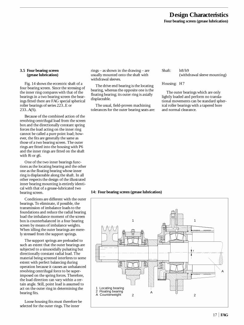
3.5 Four bearing screen (grease lubrication)
Fig. 14 shows the eccentric shaft of afour bearing screen. Since the stressing ofthe inner ring compares with that of thebearings in a two bearing screen the bear-ings fitted there are FAG special sphericalroller bearings of series 223..E or233..A(S).
Because of the combined action of therevolving centrifugal load from the screenbox and the directionally constant springforces the load acting on the inner ringcannot be called a pure point load; how-ever, the fits are generally the same as those of a two bearing screen. The outerrings are fitted into the housing with P6and the inner rings are fitted on the shaftwith f6 or g6.
One of the two inner bearings func-tions as the locating bearing and the otherone as the floating bearing whose innerring is displaceable along the shaft. In allother respects the design of the illustratedinner bearing mounting is entirely identi-cal with that of a grease-lubricated twobearing screen.
Conditions are different with the outerbearings. To eliminate, if possible, thetransmission of imbalance loads to the foundations and reduce the radial bearingload the imbalance moment of the screenbox is counterbalanced in a four bearingscreen by means of imbalance weights.When idling the outer bearings are mere-ly stressed from the support springs.
The support springs are preloaded tosuch an extent that the outer bearings aresubjected to a sinusoidally pulsating butdirectionally constant radial load. Thematerial being screened interferes to someextent with perfect balancing duringoperation because it causes an unbalancedrevolving centrifugal force to be super-imposed on the spring forces. Therefore,the load direction can vary within a cer-tain angle. Still, point load is assumed toact on the outer ring in determining thebearing fits.
Loose housing fits must therefore beselected for the outer rings. The inner
rings – as shown in the drawing – areusually mounted onto the shaft withwithdrawal sleeves.
The drive end bearing is the locatingbearing, whereas the opposite one is thefloating bearing; its outer ring is axiallydisplaceable.
The usual, field-proven machining tolerances for the outer bearing seats are:
Shaft: h8/h9 (withdrawal sleeve mounting)
Housing: H7
The outer bearings which are onlylightly loaded and perform no transla-tional movements can be standard spher-ical roller bearings with a tapered boreand normal clearance.
17 FAG
14: Four bearing screen (grease lubrication)
1
2
1 Locating bearing2 Floating bearingA Counterweight
1
2A
A
r

LubricationGrease lubrication
4 Lubrication
Spherical roller bearings in vibratingmachines are subjected to very high oper-ating loads and adverse environmentalconditions. The lubricant type, lubrica-tion system and lubricant supply have tobe selected carefully and adapted to therequirements on the functionability andservice life of the vibrating machine bear-ings.
Depending on the operating condi-tions, the bearing size and specific re-quirements of the plant operator, eithergrease lubrication or oil lubrication canbe selected.
4.1 Grease lubrication
In most vibrating machines the specialspherical roller bearings are lubricatedwith grease. Grease lubrication is com-monly used up to speed indices of n · dm = 300 000 min–1 · mm (n operat-ing speed, dm mean bearing diameter).Only field-proven and tested greasesshould be used, see section 4.3. If pos-sible, the grease type used should not bechanged.
For the usual operating conditions invibrating machines, we recommend touse lithium soap base greases with EP ad-ditives and anti-corrosion additives of penetration class 2. The minimum re-quirements defined in DIN 51 825 arenot sufficient for this application. Rather,the suitability of a lubricating grease forrolling bearings must have been proved,as is the case, for instance, with the FAGgreases Arcanol L135V and L186V.
For applications where higher operat-ing temperatures have to be accommo-dated, e.g. in screens for hot material, orwhere the bearings under certain condi-tions are quite considerably heated by thematerial to be screened it is a good idea touse special greases which are not impairedby high temperatures.
The required base oil viscosity dependson the operating conditions. A viscosityratio of � = �/�1 ≥ 2 should be aimed at.� is the operating viscosity, �1 is the ratedviscosity, see also FAG catalogue WL 41 520.
As the bearings are assembled, their cavities have to be packed with grease tocapacity. To avoid excessive working ofthe lubricant, the housing cavities onboth sides of the bearing must remainempty so that excessive grease can dis-perse into the housing cavities during thestart-up period.
It is good practice to relubricate thebearings through the lubricating grooveand the three lubricating holes in the outer ring which are a standard feature ofall FAG special spherical roller bearings.In this way an even lubricant supply toboth roller rows is ensured.
For applications where the bearings arerelubricated laterally the distance betweenhousing wall and bearing face on thegrease supply side should be as small aspossible so that the grease can get into thebearing quickly and without losses.
It is also good practice to relubricatevibrating machine bearings with relativelysmall quantities of grease at short inter-vals.
The table, fig. 15, shows the replenish-ment quantities in dependence on bear-ing size and speed. These grease quanti-ties apply to a relubrication interval of 50 operating hours and normal operatingtemperatures.
If the bearings are continuously relu-bricated by means of a central lubricatingsystem the grease quantity m1 requiredper hour and bearing can be determinedby means of the following equation:
m1 = 0.00004 · D · B
where
m1 = required grease quantity [g/h]
D = bearing O.D. [mm]
B = bearing width [mm]
The labyrinth seals have to be relubri-cated once a week; if necessitated by un-favourable operating conditions (expo-sure to great amounts of dust, moisture,high operating temperature), more fre-quently. They should be packed with thesame grease as the rolling bearings.
FAG 18

LubricationGrease lubrication · Oil lubrication
4.2 Oil lubrication
Speeds above the range suitable forgrease lubrication (i. e. speed index n · dm > 300 000 min–1 · mm) require oillubrication. Lubrication with oil may alsobe required for applications where thebearings are exposed to external heating.Maintenance may be another reason foroil lubrication.
We recommend to lubricate the bear-ings either with mineral oils or with syn-thetic oils containing EP additives and
anti-corrosion additives, see also section4.3. Good-quality multigrade oils mayalso be used.
The viscosity ratio � = �/�1 (� = oper-ating viscosity, �1 = rated viscosity)should be ≥ 2.
4.2.1 Oil sump lubrication (oil bath lubrication)
Oil sump lubrication is normally usedup to a speed index of n · dm = 300 000 min–1 · mm; if the oil is changed
frequently, even up to n · dm = 500 000 min–1 · mm. With this lubrica-tion system the lubricant is taken to therolling contact areas by existing gear-wheels, by the imbalance mass or by therolling elements themselves.
For this purpose the oil level in theplant, i.e. in the bearing housing, must behigh enough for the gearwheels or im-balance masses to plunge into the oil dur-ing operation and churn it. When thebearing is at rest, the bottommost rollermust be half immersed in oil, fig. 16.
19 FAG
15: Replenishment quantities for spherical roller bearings in vibrating machines (relubrication interval: 50 operating hours)
Bore Speed min–1
reference 500 600 700 800 900 1000 1200 1400 1600 1800 2000 2200 2400 2600 2800 3000 3200number
08 Grease quantities in g approx. 509 for bearing series 223/233 10/– 10/–10 10/– 10/– 10/– 10/– 15/–
11 /10 10/10 10/10 10/10 10/15 15/15 15/20 20/2012 ca. 5 /10 /10 10/10 10/10 10/10 10/15 15/15 15/2013 10/10 10/10 10/10 10/10 15/15 15/20 20/25
14 10/10 10/10 10/10 15/15 15/20 20/25 25/3015 /10 10/10 10/10 10/15 15/15 20/25 25/3016 /10 /10 10/10 10/10 10/10 10/10 10/15 15/20 20/25 25/30
17 /10 /10 10/10 10/10 10/10 10/10 10/15 15/20 20/25 25/30 35/4018 10/10 10/10 10/10 10/10 10/10 10/10 15/15 20/20 25/30 30/35 40/5019 10/10 10/10 10/10 10/10 10/15 15/15 15/20 25/30 35/40 45/55
20 10/10 10/10 10/10 10/15 15/15 15/20 20/25 30/35 40/4522 10/10 10/15 15/15 15/20 20/20 20/25 30/40 50/55 70/7524 15/15 15/20 20/20 25/25 30/35 35/45 55/70 85/110
26 15/20 20/25 20/25 25/30 35/40 40/50 65/8028 20/25 25/30 30/35 35/45 45/55 60/70 100/12030 25/30 30/35 40/45 50/60 65/80 90/100
32 25/30 35/45 45/55 60/70 80/95 100/12034 30/35 40/50 55/65 80/90 110/130 140/17036 35/45 50/60 65/75 90/105 120/150
38 45/55 65/75 90/105 130/15040 50/60 70/85 100/120 150/18044 70/85 105/125 160/200
48 105/130 170/21052 120/150 200/24056 190/240

LubricationOil lubrication
A sufficiently large quantity of oil in-creases the oil change interval. If thehousing cavities are insufficient the shaftguard tube between the bearings is usedas an additional reservoir. Otherwise, anextra oil tank will have to be provided.
The oil change interval depends on thecontamination and the ageing conditionof the oil. Fig. 17 shows recommendedoil quantities and oil change intervals as afunction of the bearing bore. For moredetails, see FAG Publ. No. WL 81 115/4EA "Rolling Bearing Lubrication".
We recommend to inspect the oil reg-ularly in order to determine the requiredoil change intervals more accurately basedon the results of these inspections.
FAG 20
16: Determination of the oil level with the bearing at rest
b a
a is the normal oil levelb is the minimum oil level
Bore reference Bearing series 223 and 233number a b
mm
08 31 3409 35 3810 39 42
11 42 4612 46 5013 50 54
14 54 5915 58 6216 62 67
17 66 7118 69 7419 72 78
20 78 8422 86 9424 93 101
26 100 10928 107 11730 115 125
32 122 13334 129 14036 137 149
38 144 15640 152 16544 168 182
48 182 19552 196 21156 212 228
LubricationOil lubrication
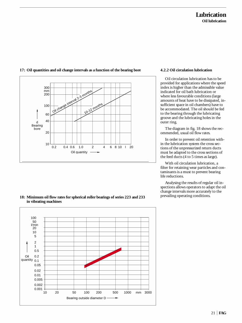
4.2.2 Oil circulation lubrication
Oil circulation lubrication has to beprovided for applications where the speedindex is higher than the admissible valueindicated for oil bath lubrication or where less favourable conditions (largeamounts of heat have to be dissipated, in-sufficient space in oil chambers) have tobe accommodated. The oil should be fedto the bearing through the lubricatinggroove and the lubricating holes in theouter ring.
The diagram in fig. 18 shows the rec-ommended, usual oil flow rates.
In order to prevent oil retention with-in the lubrication system the cross sec-tions of the unpressurized return ductsmust be adapted to the cross sections ofthe feed ducts (4 to 5 times as large).
With oil circulation lubrication, a filter for retaining wear particles and con-taminants is a must to prevent bearinglife reductions.
Analysing the results of regular oil in-spections allows operators to adapt the oilchange intervals more accurately to theprevailing operating conditions.
21 FAG
17: Oil quantities and oil change intervals as a function of the bearing bore
300mm200
100
60
40
20
100.2 0.4 0.6 1.0 2 4 6 8 10 l 20
dBearing
bore
Oil quantity
Oil change interval 2-3months
10-12 months
18: Minimum oil flow rates for spherical roller bearings of series 223 and 233 in vibrating machines
10050
l/min2010
210.5
0.20.10.05
0.020.010.005
0.0020.001
10 20 50 100 200 500 1000 mm 3000
Oilquantity
Bearing outside diameter D
5

LubricationRecommended lubricants
FAG 22
4.3 Recommended lubricants
Greases for vibrating screen bearings
The quality of the FAG rolling bearinggreases Arcanol is carefully monitored by100 % inspection of every batch.
Greases for normal temperatures:Arcanol L135VArcanol L186VArcanol L215 V
Grease for high temperatures:Arcanol L195V
FAG cannot make any statements con-cerning batch variations, formulationchanges or influences of production ongreases that do not pass through ourgoods inwards inspection. However, FAGkeeps a list of suitable commercial greaseswhich is continuously updated. The currently valid list can be ordered fromFAG under the telephone number (0 97 21) 91 38 83.
Oils for vibrating screen bearings
The additives of oils used for thisapplication must be proved to be effectivein rolling bearings. As a rule, both miner-al and synthetic oils can be used, with theexception of silicone oils. Oils with vis-cosity index improvers are not recom-mendable. An up-to-date list of recom-mendable oils can be ordered from FAG under the telephone number (0 97 21) 91 38 83.

FAG Special Spherical Roller Bearings for Vibrating Machineswith a cylindrical bore
Series 223E.T41A
Shaft Dimensions Load rating Limiting Reference Code Massdyn. stat. speed speed
d D B rs ns H J1 C C0 Bearing ≈min ≈ ≈
mm kN min–1 FAG kg
40 40 90 33 1.5 4.8 77 52 129 143 7500 7000 22308E.T41A 0.984
45 45 100 36 1.5 6.5 86 58 156 176 6700 6300 22309E.T41A 1.36
50 50 110 40 2 6.5 94 63 190 216 6000 6000 22310E.T41A 1.87
55 55 120 43 2 6.5 102 68 224 255 5600 5600 22311E.T41A 2.02
60 60 130 46 2.1 6.5 111 74 260 300 5000 5000 22312E.T41A 2.8
65 65 140 48 2.1 9.5 120 83 290 355 4800 4500 22313E.T41A 3.57
70 70 150 51 2.1 9.5 129 86 325 375 4500 4300 22314E.T41A 4.25
75 75 160 55 2.1 9.5 137 92 375 440 4300 3800 22315E.T41A 5.01
80 80 170 58 2.1 9.5 146 98 415 500 4300 3600 22316E.T41A 6.27
85 85 180 60 3 9.5 155 104 455 540 4000 3200 22317E.T41A 6.84
90 90 190 64 3 12.2 163 110 510 620 3600 3000 22318E.T41A 8.08
95 95 200 67 3 12.2 172 115 560 680 3000 2800 22319E.T41A 9.21
100 100 215 73 3 12.2 184 124 655 815 3000 2600 22320ED.T41A 12
110 110 240 80 3 15 206 143 800 1060 2600 2200 22322ED.T41A 17.4
120 120 260 86 3 15 224 150 900 1140 2600 2000 22324ED.T41A 21
130 130 280 93 4 17.7 241 162 1040 1340 2400 1900 22326ED.T41A 27.1
140 140 300 102 4 17.7 257 173 1220 1600 2200 1700 22328ED.T41A 34
150 150 320 108 4 17.7 274 185 1370 1830 2000 1500 22330ED.T41A 40.6
23 FAG
H DdJ1
B
ns
rs
rs

FAG Special Spherical Roller Bearings for Vibrating Machineswith a cylindrical bore
Series 223A.MA.T41ASeries 233A(S).MA.T41A
Shaft Dimensions Loat rating Limiting Reference Code Massdyn. stat. speed speed
d D B rs ns H C C0 Bearing ≈min ≈
mm kN min–1 FAG kg
160 160 340 114 4 17.7 289 1430 1900 2000 1500 22332A.MA.T41A 52.7
170 170 360 120 4 17.7 305 1600 2120 1800 1400 22334A.MA.T41A 59.5
180 180 380 126 4 23.5 324 1760 2360 1500 1300 22336A.MA.T41A 72.2
190 190 400 132 5 23.5 339 1860 2500 1500 1200 22338A.MA.T41A 81
200 200 420 138 5 23.5 359 2080 2800 1400 1100 22340A.MA.T41A 93.5
220 220 460 145 5 23.5 392 2320 3350 1300 950 22344A.MA.T41A 120
Shaft Dimensions Load rating Limiting Code Massdyn. stat. speed
d D B rs ns H C C0
min ≈ Bearing ≈
mm kN min–1 FAG kg
100 100 215 82.6 3 9.5 180 680 900 2800 23320AS.MA.T41A 15.3
110 110 240 92.1 3 12.2 201 830 1080 2600 23322AS.MA.T41A 21.1
120 120 260 106 3 12.2 216 1020 1430 2400 23324AS.MA.T41A 28.9
130 130 280 112 4 12.2 233 1160 1600 2200 23326AS.MA.T41A 35.3
140 140 300 118 4 12.2 250 1270 1800 2000 23328AS.MA.T41A 40.7
150 150 320 128 4 15 266 1500 2120 2000 23330A.MA.T41A 49.8
160 160 340 136 4 17.7 282 1660 2320 2000 23332A.MA.T41A 62.6
190 190 400 155 5 17.7 334 2200 3200 1400 23338A.MA.T41A 97.1
200 200 420 165 5 17.7 351 2450 3600 1300 23340A.MA.T41A 108
FAG 24
d H D
ns
rs
B
rs

Every care has been taken to ensure thecorrectness of the information contained inthis publication but no liability can beaccepted for any errors or omissions.We reserve the right to make changes inthe interest of technical progress.© by FAG 2000. This publication or partsthereof may not be reproduced withoutour permission.
WL 21 100/3 EA/96.5/12/00
FAG OEM und Handel Aktiengesellschaft
Postfach 1260D-97419 SchweinfurtGeorg-Schäfer-Strasse 30D-97421 SchweinfurtTel. +49 (0) 97 21 / 91 38 83Fax +49 (0) 97 21 / 91 39 58E-mail: [email protected]