Faculty of Engineering - UNIMAS Institutional Repository Piping and Drainage System in a... ·...
24
Faculty of Engineering WATER PIPING AND DRAINAGE SYSTEM IN A BUILDING Domincie Anak Winston Bale Bachelor of Engineering with Honours (Civil Engineering) 2006
Transcript of Faculty of Engineering - UNIMAS Institutional Repository Piping and Drainage System in a... ·...

Faculty of Engineering
WATER PIPING AND DRAINAGE SYSTEM IN A BUILDING
Domincie Anak Winston Bale
Bachelor of Engineering with Honours (Civil Engineering)
2006
UNIVERSITI MALAYSIA SARAWAK
R13a BORANG PENGESAHAN STATUS TESIS
WATER PIPING AND DRAINAGE SYSTEM IN A BUILDING
____________________________________________________________________________
SESI PENGAJIAN: 2005/2006
DOMINCIE ANAK WINSTON BALE (8138) Mengaku membenarkan tesis *ini disimpan di pusat Khidmat Maklumat Akademik, Universiti Malaysia Sarawak dengan syarat-syarat kegunaan seperti berikut: 1. Tesis adalah hakmilik Universiti Malaysia Sarawak. 2. Pusat Khidmat Maklumat Akademik, Universiti Malaysia Sarawak dibenarkan membuat salinan untuk tujuan pengajian sahaja. 3. Membuat pendigitan untuk mambangunkan Pangkalan Data Kandungan Tempatan. 4. Pusat Khidmat Maklumat Akademik, Universiti Malaysia Sarawak dibenarkan membuat salinan Tesis ini sebagai bahan pertukaran antara institusi pengajian tinggi. 5. ** Sila Tandakan ( ) di kotak yang berkenaan (TANDATANGAN PENULIS) (TANDATANGAN PENYELIA) 622, Lorong B1, Taman BDC Stampin, 93350, Kuching, Sarawak 7th April 2006
DR. AZHAILI BAHARUN Nama Penyelia Tarikh: Tarikh:
Alamat tetap:
(Mengandungi maklumat yang berdarjah keselamatan atau kepentingan Malaysia seperti yang termaktub di dalam AKTA RASMI 1972)
(Mengandungi maklumat TERHAD yang telah ditentukan oleh organisasi/badan di mana penyelidikan dijalankan).
SULIT TERHAD TIDAK TERHAD
Saya:
Judul:
CATATAN * Tesis dimaksudkan sebagai tesis bagi Ijazah Doktor Falsafah, Sarjana dan sarjana Muda. ** Jika tesis ini SULIT atau TERHAD, sila lampirkan surat daripada pihak berkuasa/organisasi berkenaan dengan menyatakan sekali sebab dan tempoh tesis ini perlu dikelaskan sebagai SULIT dan TERHAD.

Laporan Projek Tahun Akhir berikut:
Tajuk: WATER PIPING AND DRAINAGE SYSTEM IN A BUILDING
Nama Penulis: DOMINCIE ANAK WINSTON BALE
Matrik: 8138
Telah dibaca dan disahkan oleh:
______________________ ___________________
Dr. Azhaili Baharun Date

WATER PIPING AND DRAINAGE SYSTEM IN A BUILDING
by
Domincie Anak Winston Bale
A Case Study Report Submitted
To Faculty of Engineering, Universiti Malaysia Sarawak
In partial fulfillment for the degree of
Bachelor of Engineering (Hons) Civil Engineering
2006

To my beloved family


DECLARATION
No portion of the work referred to in this dissertation has been submitted in support
of an application for another degree or qualification of this or any other university of
higher learning.
___________________
(Domincie Anak Winston Bale)
iii

ACKNOWLEDGEMENTS
I would like to thank father, Winston Bale Utot, my mother, Bagline Melana and my
siblings Danny, Marvin and Beatrice, who prays for my success and provide me with
enough courage in completing this thesis research.
Special thanks are especially dedicated to my supervisor, Dr. Azhaili Baharun who
also happens to be the Dean of Department of Engineering UNIMAS, for his ideas,
guidance and motivation during the preparation of the thesis research: thanks for your
concern. Not forgetting Mr. Awang Mohd. Fadilah from Jabatan Kerja Raya (JKR)
Building section for providing valuable resources in assisting the research.
Last but not least to my entire course mate for giving assistance and support in
providing the information and whole-hearted support till the end.
iv
ABSTRAK
Sistem saliran dan perparitan merupakan sebahagian dari sistem bangunan yang perlu
diberi perhatian sepenuhnya terutama daripada jurutera bangunan, arkitek dan pihak-
pihak yang terbabit dalam memelihara kedua-dua sistem tersebut. Sistem saliran air
biasanya terbahagi kepada sistem saliran air sejuk dan sistem saliran air panas yang
membekalkan pengaliran air ke seluruh bangunan terutamanya ke saluran keluar yang
paling tinggi semasa keadaan kemuncak. Penentuan saiz paip yang tepat adalah perlu
untuk mengelakkan berlakunya peningkatan tekanan disebabkan oleh ketidaktentuan
dalam halaju air semasa pengaliran. Oleh itu penentuan kadar aliran air untuk setiap
peralatan dan pepasang yang terdapat pada setiap bangunan adalah penting bagi
membantu menentukan saiz paip yang digunakan, seperti yang terkandung dalam
Kriteria Rekaan dan Piawaian dalam Sistem Aliran Air JKR (1994). Hasil
penyelidikan yang terkandung dalam kertas ini melibatkan penentuan saiz paip pada
setiap asrama dengan mengetahui unit bebanan pada setiap pepasang dan peralatan
yang sedia ada. Untuk penentuan saiz paip sisa, paip bolong dan paip pengudaraan,
setiap unit luahan untuk setiap pesang yang digunakan adalah berdasarkan Piawaian
British BS 5572: 1978.
v

ABSTRACT
Water piping and drainage system are the 2 most important building systems that
require much attention to all engineers, architects and those related in the field. Water
piping are usually include hot and cold water distribution system that are supplied
throughout the entire building the means of pumping or applying the water main to
maintain the water pressure in order to assure that the highest outlet has an adequate
water flow during crucial time. Determination of the right size of a pipe is essential to
avoid excessive water pressure due to inadequate velocity in pipes. By doing so, is
vital to determine the design flow rate of each fixture in buildings which has been
stated in JKR Design Criteria and standards for Water Supply System. This
dissertation is about the determination of pipe size used in the hostels by knowing its
loading unit that assigned to each of the fixtures available. For sanitary drainage
fixture unit, the fixtures are assigned based on British Standard 5572: 1978 revision,
which used to determine the pipe size of soil pipe, vent pipe and waste pipe.
vi
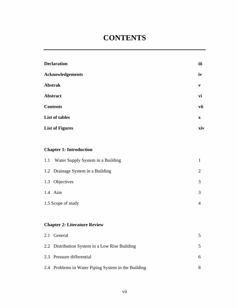
CONTENTS
Declaration iii
Acknowledgements iv Abstrak v
Abstract vi
Contents vii
List of tables x
List of Figures xiv Chapter 1: Introduction 1.1 Water Supply System in a Building 1
1.2 Drainage System in a Building 2
1.3 Objectives 3
1.4 Aim 3
1.5 Scope of study 4
Chapter 2: Literature Review 2.1 General 5
2.2 Distribution System in a Low Rise Building 5
2.3 Pressure differential 6
2.4 Problems in Water Piping System in the Building 8
vii

2.4.1 Noise 8
2.4.2 Water Hammer 8
2.4.3 Velocity 10
2.4.4 Pulsation 10
2.4.5 Leakage 11
2.5 Pipes of Water Distribution System in a Building 12
2.5.1 Cast Iron (C.I) or Grey Iron Pipes 12
2.5.2 Ductile Iron (D.I) Pipes 13
2.5.3 Polyethylene (PE) Pipes 14
2.5.4 Unplasticised Polyvinyl Chloride (uPVC) Pipes 14
2.6 Selection of Type of Pipes 16
2.7 Joints 16
2.7.1 Flanges Joint 16
2.7.2 Welded Joint 17
2.7.3 Single Gland – Mechanical Joint 18
2.8 Pipe Fittings in a Building 19
2.8.1 Tapers 21
2.8.2 Flange Adaptors 21
2.8.3 Bends 22
2.8.4 Tees 23
2.8.5 Angle Branches and Crosses 24
2.8.6 Puddle Flange 25
2.8.7 Bellmouth 25
viii

2.8.8 Rose Strainer 26
2.8.9 Blank Flanges 26
2.9 Minor losses 27
2.10 Storage Cisterns 29
2.11 Rate of flow of Fittings and Appliances 30
2.12 Estimating the Total Demand of A supply System in a Building 31
2.12.1 Load Values (WSFU) Assigned to Fixtures 31
2.13 Effective Length of Pipe Run 32
2.13.1 Loss of Head through Pipes, Fitting and Valves 32
2.14 Drainage System in a Building 34
2.14.1 Sanitary Drainage System 34
2.14.2 Vent System 35
2.14.3 Roof Drainage System 37
2.15 Sanitary Drainage Fixture Units 38
Chapter 3: Methodology 3.1 Introduction 40
3.2 Design of a Pipework System in a Building 40
3.3 Detailed Method of Sizing Systems in Buildings of Any Height 41
3.4 Method of Sizing of Sanitary Piping System in Buildings
At Any Height 45
ix

Chapter 4: Analysis, Result and Discussion 4.1 Introduction 47
4.2 Pipe Sizing Calculation for Apartment Type A and B 66
4.3 Sizing of sanitary drainage pipe for Apartment Type A and B 80
4.4 Discussion 85
4.4.1 Factors Determine the Required Water Supply
Pipe Size in Buildings 85
4.4.2 Factors Determine the Required Sanitary Drainage
Pipe Size in Buildings 86
Chapter 5: Conclusion and Recommendation 5.1 Conclusion 88
5.2 Recommendation 89
References 90
Appendices 92
x

LIST OF TABLES
Table 2.0 : Thickness and Diameter Specification for Cast Iron Pipe 13
Table 2.1 : Comparison between UPVC and HDPE Pipes
(Taken from Env. Canada, PVC-Free Pipe Purchasers’ Report) 15
Table 2.2 : Joint and Specials for Selected Pipe Materials 19
Table 2.3 : Minor Loss Coefficients (K) 28
Table 2.4 : Minimum Storage Capacity 29
Table 2.5 : Storage Requirements Per Person 30
Table 2.6 : Storage Requirement Per Fittings in a Building 30
Table 2.7 : Minimum Recommended Flow 31
Table 2.8 : Loading Units in Buildings 32
Table 2.9 : Equivalent Pipe Length for Copper 33
Table 2.10 : Equivalent of Pipe Length through Resistance 33
Table 2.11 : For Frictional Resistance of draw-off taps
(Equivalent Pipe Length) 34
Table 2.12 : Sanitary Drainage Fixture Unit Values
(Taken from BS 5572: 1978) 38
Table 2.13 : Maximum Permissible Loads for Sanitary
Drainage Piping (In terms of fixture units)
(Taken from BS 5572: 1978) 38
xi

Table 2.14 : Maximum Permissible Concentrated Waste
Drainage Piping (Taken from BS 5572: 1978) 39
Table 4.0 : Flow rate requirement for buildings 3 Storey and
above – For Supply to Sinks Showers, WCs and
Wash Basins (Type A) 63
Table 4.1 : Flow rate requirement for buildings 3 Storey and
above – For Supply to Sinks Showers, WCs and
Wash Basins (Type B) 63
Table 4.2 : Flow rate Requirement for Building 3 Storey and
above – For Filling Roof Tank (Type A and Type B) 64
Table 4.3 : Pipe Sizing Calculation and Data Input for
Branch No. 1 67
Table 4.4 : Pipe Sizing Calculation and Data Input for
Branch No. 2 68
Table 4.5 : Pipe Sizing Calculation and Data Input for
Branch No. 3 69
Table 4.6 : Pipe Sizing Calculation and Data Input for
Branch no. 4 70
Table 4.7 : Pipe Sizing Calculation and Data Input for
Branch No. 5 71
Table 4.8 : Pipe Sizing Calculation and Data Input for
Branch No. 1 72
xii

Table 4.9 : Pipe Sizing Calculation and Data Input for
Branch No. 2 73
Table 4.10 : Pipe Sizing Calculation and Data Input for
Branch No. 3 74
Table 4.11 : Pipe Sizing Calculation and Data Input for
Branch No. 4 75
Table 4.12 : Pipe Sizing Calculation and Data Input for
Branch No. 5 76
Table 4.13 : 4th Floor Level Sizing 80
Table 4.14 : 3rd Floor Level Sizing 81
Table 4.15 : 2nd Floor Level Sizing 82
Table 4.16 : 1st Floor Level Sizing 83
Table 4.17 : Sizing of Main Pipes 84
xiii

LIST OF FIGURES
Figure 2.0 : An upfeed water distribution system in a low rise
building using single pressure zone 6
Figure 2.1 : Graphic illustration of shock wave 9
Figure 2.2 : Flanges Joint 17
Figure 2.3 : Welded Joint 18
Figure 2.4 : Single Gland – Mechanical Joint 18
Figure 2.5 : Tapers 21
Figure 2.6 : Flange Adaptors 22
Figure 2.7 : Bends 23
Figure 2.8 : Tees 24
Figure 2.9 : Angle Branches and Crosses 24
Figure 2.10 : Puddle Flange 25
Figure 2.11 : Bellmouth 26
Figure 2.12 : Rose Strainer 27
Figure 2.13 : Branch Vent 35
Figure 2.14 : Continuous Vent 36
Figure 2.15 : Common Vent 37
Figure 2.16 : Loop Vent 38
Figure 4.0 : Branch no.1 (Apartment type A)
Figure 4.1 : Branch no.2 (Apartment type A)
xiv

Figure 4.2 : Branch no.3 (Apartment type A) 50
Figure 4.3 : Branch no.4 (Apartment type A) 51
Figure 4.4 : Branch no.5 (Apartment type A) 52
Figure 4.5 : Branch no.1 (Apartment type B) 56
Figure 4.6 : Branch no.2 (Apartment type B) 57
Figure 4.7 : Branch no.3 (Apartment type B) 58
Figure 4.8 : Branch no.4 (Apartment type B) 59
Figure 4.9 : Branch no.5 (Apartment type B) 60
Figure 4.10 : Soil and Waste Schematic Diagram for Apartment
Type A and Type B (From 4th floor to 3rd floor
continued next page) 77
Figure 4.11 : Soil and Waste Schematic Diagram for Apartment
Type A and Type B (From 2nd floor to 1st floor) 78
xv

1
CHAPTER 1
INTRODUCTION
1.1 Water Supply System in a Building
Piping system can be defined as a series of pipe networks that connect with one
after another from one junction known as nodes distributing water supply to all parts
of the building. In most cases, water supply system includes water service pipe and
the water-distributing pipe. More specifically piping system in a building covers
much on categories such as kind of piping networks used, selection of pipes from
manufacturer, code of practice used in installing and servicing the pipes and
maintenance of piping system in a building itself. As a building engineer, one must
know the criteria needs for a building to keep its water flows steady without any
problem or errors occurred during its lifetime period.
In buildings, pipe engineering plays a vital part in understanding the regularities
of building services so that each of the aspect safety, maintenance and life span of the
building can be elongated. Criteria that need to be emphasized in determining the
right pipe to be installed in a building are the diameter of pipes used, the flowrates
from each inlets and outlets, headloss and pressures where ‘water flows in a pipe
from a high point of high pressure to a point of lower pressure’ [3]. Crucial as before,

2
the variety of pipes need to be identified to determine whether or not the pipe is
suitable for all climates. Pipe system also needs maintenance throughout its entire
life. Maintenance included detection of possible problems encountered such as
corrosion, water hammers, unsteady pressures (shock wave) and leakage.
Knowing the past records of water consumption demand and the peak factor, we
could possibly sort out the approximate the peak demand for each of the building and
predict the how much it consumes for a day. Each pipe is serviced, analyze and
monitor to determine the life span of pipes in each network system.
1.2 Drainage System in a Building
Another vital aspect of building services is drainage system. It can be defined as
a system of piping within private or public premises that conveys sewage (i.e., any
liquid waste containing animal, vegetable, or chemical wastes in solution), rainwater,
or other liquid wastes to an approved point of disposal, which does not include the
mains of a public sewer system. The presence of the drainage system in all buildings
is to ensure proper drainage clean, sanitary condition of human life. The gravity
drainage system is commonly used in all building all over the world and a trap to
eliminate stench and vermin is introduced in sanitary facilities. Actual discharge of a
drainage pipe is complex phenomenon may consist of water air and solids; airflow in
drainage stack is promoted through mixing and friction from the falling water. It
causes negative pressure originated from the upper floor and positive pressure on the
lower floor in the building. The impact of inconsistency may create the destruction of

3
water seals in the trap and causes many sanitary problems in a building drainage
system in a building [2]. Further explanation of drainage system in a building can be
referred in chapter 2.
1.3 Objectives
As part of the requirement in conducting the final year project, the objectives are:
a) To determine the required standards used in servicing and installing pipes in
pipe system and recognizing the type of pipe were used;
b) To give detail data analysis on flowrate on selected buildings by determining
the loading unit of each fixtures;
c) To give detail data analysis on Sanitary Drainage Fixture Unit (SDFU) for
sizing the sanitary pipes in a building.
1.4 Aim
The specific aim for this project is to come out with a data that can improve the
current piping system in the building thus gives solution towards the corresponding
problem. It is to ensure adequate water supply to all fixtures at all times and to
achieve economic sizing of piping.
4
1.5 Scope of study
This study covers 2 current hostels in UNIMAS temporary campus. The chosen
one is Kenari Collage. Kenari College was situated on the right side of the main
temporary campus which accommodate up to 120 students per hostel. The figures are
estimated based on number of student per apartment (1 apartment = 8 students).
Numbers of apartment are 5 per floor which for the entire 4-storey building is 120
students in total, excluding the ground floor. The provision of cold water supply
were channeled through out the entire building using an upfeed system, elevating the
water through a series of pumping booster from the ground originated from the pre-
steel tank with a dimension of [2400 x 3600 x 1200 (H) ] mm3 . The pre-steel water
tank is able to supply up to 2400 gallons of water for both blocks during crucial
times.

5
CHAPTER 2
LITERATURE REVIEW
2.1 General
Most buildings are equipped with domestic water system with the sole purpose
to provide a safe, healthy supply of potable water, at an adequate temperature and
pressure, to all plumbing fixtures within a building. Furthermore the water
distribution system varies materially from the drain, waste and vent system.
2.2 Distribution System in a Low Rise Building
Distribution system for 4 to 5 storey high buildings is using an upfeed system
where the pressure is sufficient enough to distribute water throughout an entire
building. Distributions to all floors are done by implementing a single pressure zone
in which it uses the water main as the source of water supply for continuous
supplying. The height that served without pumps to boost the water pressure depends
on the available pressure in the water main, the requirement of the fixtures, and
applicable plumbing code. When there is no flow in the building, the condition is
known as static pressure but once the water flows in the system the pressure will
subsequently loss due to friction losses. From here the residual pressure is obtained