Faculty of Electrical Engineering - cvut.cz · ... doc. Ing. Zdenek Becvar, ... maintains global...
35
CZECH TECHNICAL UNIVERSITY IN PRAGUE Faculty of Electrical Engineering Department of Electromagnetic Field Device-to-Device communication in networks with small cells May 2015 Bachelor: Evgenia Sokolova Thesis advisor: doc. Ing. Zdenek Becvar, Ph.D.
Transcript of Faculty of Electrical Engineering - cvut.cz · ... doc. Ing. Zdenek Becvar, ... maintains global...
CZECH TECHNICAL UNIVERSITY IN PRAGUE
Faculty of Electrical Engineering Department of Electromagnetic Field
Device-to-Device communication in networks with small cells
May 2015 Bachelor: Evgenia Sokolova
Thesis advisor: doc. Ing. Zdenek Becvar, Ph.D.

Čestné prohlášení
Prohlašuji, že jsem zadanou bakalářskou práci zpracoval sám s přispěním vedoucího práce a
konzultanta a používal jsem pouze literaturu v práci uvedenou. Dále prohlašuji, že nemám
námitek proti půjčování nebo zveřejňování mé bakalářské práce nebo její části se souhlasem
katedry.
Datum: 22. 5. 2015 ………………..……………………
podpis bakalanta

Zadání
Seznamte se s možnostmi přímé komunikace mezi dvěma mobilními stanicemi bez využití
základnové stanice v mobilních sítích LTE. Zhodnoťte možnosti rozhodnutí o využití přímé
komunikace mezi mobilními stanicemi. Za pomoci simulací zjistěte vhodnost a přínos přímé
komunikace pro pohybující se uživatele v heterogenních sítích s malými buňkami.
Assignment Study possibility of implementation of device-to-device communication into cellular networks
based on LTE. Analyze selected approaches of the decision on direct communication between
devices without involvement of a base station. By means of simulations, determine potential gain
and suitability of device-to-device communication for mobile users in heterogeneous networks
with small cells.
Anotace:
Tato bakalářská práce se zabývá přímou komunikací mezi mobilními uživateli v
heterogenních sítích s malými buňkami, včetně porovnání přímé komunikace mezi uživateli a
konvenční komunikací přes základnovou stanici. Veškeré simulaci práce jsou vtvořené v
programovacím prostředí Matlab. Také je věnovaná pozornost mobilitě uživatelů. Je
implementován pohybový model Probability Random Walk Mobility Model a je zhodnocen
vliv pohybu na různé režimy komunikace.
.
Klíčová slova: přímá komunikace, heterogenní sítě, malé buňky, PRWMM, model mobility.
Summary:
This thesis deals with direct-to-direct communication between mobile users in heterogeneous
networks with small cells, including comparison of direct communication between users and
conventional communication via a base station. All simulation are implemented in Matlab
programming environment. It also focuses on the mobility of users. The Probability Random
Walk Mobility Model is implemented and influence of motion on various modes of
communication is assessed.
Index Terms: device-to-device communication, heterogeneous networks, small cells, PRWMM,
mobility model

Content
1. Introduction
2. Theoretical background
2.1. European standardization of mobile network
2.2. Overview and architecture of LTE-(A)
2.3. Heterogeneous network with small cells
2.4. Device-to-device communication
3. Simulation results
4. Conclusion and future works
5. References
Abbreviations:
3G 3
rd Generation
3GPP 3rd
Generation Partnership Project
4G 4th
Generation
5G 5th
Generation
BS Base station
C Capacity
CoMP Coordinated Multi Point
CT Core Network & Terminals
D2D Device-to -Device
DSL Digital Subscriber Line
eNB Base Station (macro cell)
EPC Evolved Packet Core
EPS Evolved Packet System
ETSI European Telecommunication Standards Institute
E-UTRAN Evolved UMTS Terrestrial Radio Access Network
FDD Frequency Division Duplex
GERAN GSM EDGE Radio Access Networks
GSM Global System for Mobile Communications
HeNB Home Base Station
HetNet Heterogeneous Network
HSS Home Subscriber Server
IP Internet Protocol
LTE Long Term Evolution
LTE-A Long Term Evolution - Advanced
M2M Machine-to-Machine
MIMO Multiple Input and Multiple Output
MME Mobility Management Entity
NF Noise Figure
NP Noise Power
OFDMA Orthogonal Frequency Division Multiple Access
P2P Peer-to-peer
PDN GW Packet Data Network Gateway
PL Path Loss
PRWMM Probability Random Walk Mobility Model
QoS Quality of Service
RAN Radio Access Network
RAT Radio Access Technologies
RF Radio Frequency
RN Relay Nodes
RRH Remote Radio Heads
RSRP Reference Signal Recieved Power
SA Service & Systems Aspects
SCeNB Small Cell Base Station

SC-OFDMA Single-Carrier OFDMA
S-GW Serving Gateway
SINR Signal Noise Ratio
TDD Time Division Duplex
Tx Transceiver
UE User Equipment
UMTS Universal Mobile Telecommunications System
Figures
Figure 1. Architecture of LTE (EPC + eUTRAN)
Figure 2. Heterogeneous networks with small cells
Figure 3. Examples of D2D communication
Figure 4. The spectrum distribution of D2D communication
Figure 5. Classification of D2D communication
Figure 6. Simulation area with randomly distributed 30 SCeNBs and 150 UEs
Figure 7. The Probability Random Walk Mobility Model
Figure 8. Two scenarios of D2D location
Figure 9. D2D communication scenario
Figure 10. Conventional communication scenario
Figure 11. Decision for D2D or non D2D scenario
Figure 12. Level RSRP dependent on distance in two scenarios
Figure 13. Capacity dependency on size of the simulation area
Figure 14. Capacity dependency on velocity of UEs
Figure 15. Capacity dependency on number of users in two scenarios
Figure 16. Capacity dependency on numbers of SCeNB

Tables
Table 1. 3GPP standard releases from 2000 to 2014
Table 2. Advantages and disadvantages of Inband D2D communication
Table 3. Advantages and disadvantages of Outband D2D communication
Table 4. Main simulation assumption
1. Introduction
Sphere of mobile communications is constantly evolving, access technologies are changing,
the transmission bitrates increase, and demands for quality of services (QoS) grow. Long Term
Evolution (LTE) [1] is the considerable step forward in the movement of
mobile networks. Mobile networks of switched analog devices of 80’s have gradually evolved into
packet-only all IP services. In current time, the 3rd
Generation (3G) [2] and 4th Generation (4G) [3]
are developed under the direction of 3rd Generation Partnership Project (3GPP) [4]. Nowadays the
work on 5th Generation (5G) [5] is initiated.
The advance in technology causes continuous accrue of broadband users, a high data traffic
and necessity of huge capacity in mobile networks. One of the possible solutions is to introduce
Heterogeneous Networks (HetNet) [6] with small cells (SCeNB). HetNet should improve spectral
efficiency and energy efficiency issues [7]. Also the Device-to-device (D2D) mobile
communication, the mobile communication without assistance of base station, contributes to
enhancement of capacity in wireless networks [8].
The aim of this thesis is evaluation of communication options, simulation of different modes of
communication, including D2D. Then, two modes are compared in terms of their impact on
capacity of the network. Also, the leverage of SCeNB [9] on capacity is analyzed. Furthermore,
effects of the mobility of D2D users on the network performance are investigated.
This thesis consists of the following parts. Firstly, standardizations in mobile networks,
architecture of LTE and Heterogeneous Networks with small cells are introduced and classification
of D2D communication is described. Secondly, the implementation of two scenarios of simulation
is introduced and Probability Random Walk Mobility Model (PRWMM)[10] model is presented.
The fourth section contains description of main simulation assumptions and results of performed
experiments.
2. Theoretical background
In this chapter, standardization of mobile networks is described. Then architecture of LTE
and HetNet with small cells are introduced. Furthermore, principle and classification of D2D
communication is presented.
2.1. European standardizations of mobile networks
There are several main standardizations bodies engaged in communication technologies:
The European Telecommunication Standards Institute (ETSI) maintains global standards
for fixed, mobile radio, broadcast and Internet technologies. It was founded in 1988 as an
unprofitable organization to operate with Europe’s needs to telecommunications standardization.
Now it has more than 300 membership organizations.
The 3rd
Generation Partnership Project (3GPP) consolidates telecommunications standard
development organization for producing the Reports and Specifications which define 3GPP
technologies. 3GPP specifications are managed by member companies Working Groups and
Technical Specification Groups. Radio Access Network (RAN), Service & Systems Aspects (SA),
Core Network & Terminals (CT) and Global System for Mobile Communications (GSM EDGE
Radio Access Networks (GERAN) belong to the Technical Specification Groups. Within TSG are
Working Groups which are responsible for the Reports and Specifications in 3GPP. For example,
3GPP deal with the evolution of the GSM, the Universal Mobile Telecommunications System
(UMTS) and LTE and future mobile networks standards.
2.2. Overview and architecture of LTE(-A)
LTE is a wireless networking technology designed to provide subscribers with a secure high
performance wireless network experience. The primary assumption of LTE is that all traffic use IP.
LTE provides high data rate for communication of mobile users and determine basis for 4G LTE
Advanced. The main requirements for the LTE-A are:
high peak data rates and high quality of service,
high spectral efficiency,
improved coverage,
flexibility in frequency and bandwidth
packet-optimized system that supports multiple Radio Access Technologies(RAT)
High mobility (up to 350 km/h)[11]
Downlink based on OFDMA (Orthogonal Frequency Division Multiple Access) - 3
Gbps [12]
Uplink based on SC-OFDMA (Single-Carrier OFDMA) - 1,5 Gbps [12]
Frequency Division Duplex (FDD) a Time Division Duplex (TDD)[13]
Technology of 4G is expected to give high quality multimedia transmission over mobile
network. 4G ensures broadband connection and large capacity and end-to end digital
transmission. The target of 4G is to allow users an access to information anytime, anywhere.
Simultaneously 4G tries to make easily the issue of arrival a huge amount of data, photos and
videos, Also it fasten on complex personal services.
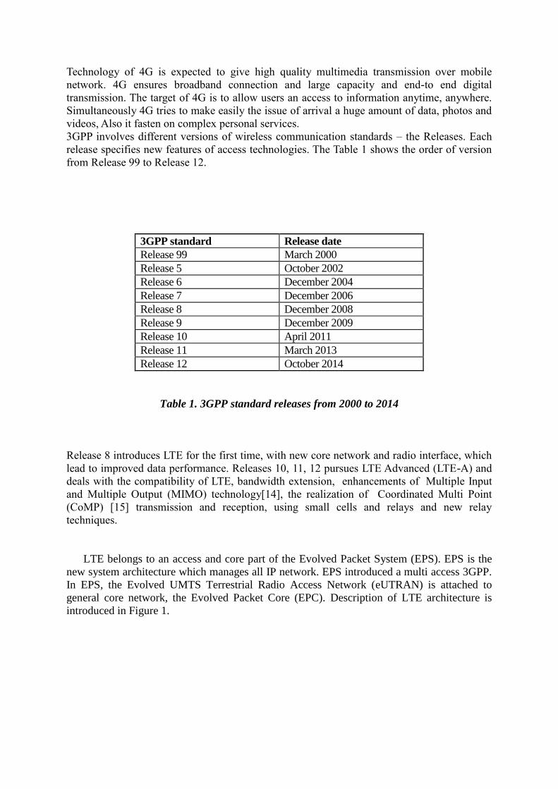
3GPP involves different versions of wireless communication standards – the Releases. Each
release specifies new features of access technologies. The Table 1 shows the order of version
from Release 99 to Release 12.
3GPP standard Release date
Release 99 March 2000
Release 5 October 2002
Release 6 December 2004
Release 7 December 2006
Release 8 December 2008
Release 9 December 2009
Release 10 April 2011
Release 11 March 2013
Release 12 October 2014
Table 1. 3GPP standard releases from 2000 to 2014
Release 8 introduces LTE for the first time, with new core network and radio interface, which
lead to improved data performance. Releases 10, 11, 12 pursues LTE Advanced (LTE-A) and
deals with the compatibility of LTE, bandwidth extension, enhancements of Multiple Input
and Multiple Output (MIMO) technology[14], the realization of Coordinated Multi Point
(CoMP) [15] transmission and reception, using small cells and relays and new relay
techniques.
LTE belongs to an access and core part of the Evolved Packet System (EPS). EPS is the
new system architecture which manages all IP network. EPS introduced a multi access 3GPP.
In EPS, the Evolved UMTS Terrestrial Radio Access Network (eUTRAN) is attached to
general core network, the Evolved Packet Core (EPC). Description of LTE architecture is
introduced in Figure 1.

Figure 1. Architecture of LTE (EPC + eUTRAN)
Architecture LTE consists of two blocks: EPC and eUTRAN.
User Equipment (UE) is the equipment, usually mobile phone, which supports the
3GPP access network.
Evolved NodeB (eNB) is a base station which provides transmission and reception
over the radio interface, modulation/demodulation and channel coding and decoding.
The eNB interlinks with other eNBs via X2 interface [16] and can communicate with
each other. Other functions of the eNB are: mobility and admission control, data
encryption and connection with MME and SGW.
Mobility Management Entity (MME) manages connection between the UE and the
network. MME supports identification mechanisms for subscribers, security and
service of bearers. Communication with the eNodeB is reached through S1 interface
[17]. MME ensures security procedures as authentication and initiation of end-users,
encoding and protections. Also MME cares about Quality of service and terminal
location management.
Serving Gateway (S-GW) is the termination spot of the interface of eUTRAN. S-GW
works as a local mobility anchor. Data packets are routed through S-GW.
Packet Data Network Gateway (PDN GW) is the termination point of the packet data
interface. PDN GW solves tasks with packet filtering and provides charging support.
The Home Subscriber Server (HSS) is a database and stores relevant information of each
authorized subscriber in 3GPP access network. HSS is accessible to MME via the S6a
interface [18].
2.3. Heterogeneous network with small cells
In the last years, the answers of following issues, as the fast growth of amount of
broadband users, data rate traffic and requirements to high capacity in mobile network are
seeking. Heterogeneous network with small cells is one of the solutions to deal with these
challenges in LTE-A technology in mobile networks.
Heterogeneous network consists of multiple cells with different characteristics: macro
cells (eNB) and SCeNB. The small cells are low-power base stations which are presented as
Home eNBs (HeNBs), Relay Nodes (RNs) or Remote Radio Heads (RRH). Macrocells
coverage usually ranges from 1 to 20 km [19]. Small and macro cells create two tier networks,
where both tiers overlap each other. SCeNB are filling in areas, which are not covered by the
macro network and enables to reuse the spectrum more efficiently, SCeNB tier increases the
capacity in hot spots (places with high user inquiry). Also, small cells improve network
performance and the quality of service, because of offloading from the large macrocell.
According to [19], small cells are classified as micro, pico and femtocells in the existing
network, which as shown in Figure 2:
Microcell covers range from 100 meters to a few kilometers
Picocell is a cell with a radius of less than 50 meters and its area may be a part
of a building, railway station, street corner, or an area of high density. Picocells
are used to enhance data capacity and to cover empty places in overlay.
Femtocell is also called home base station and it is typically placed indoors (at
home for 2-4 active subscribers or at small offices for 8-16 active subscribers).
The communication with a cellular network is realized over the Digital
Subscriber Line (DSL), cable modem, or wireless backhaul channel. The
advantage of femtocell is that the production costs of it are low.
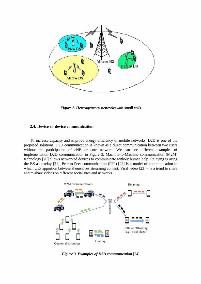
Figure 2. Heterogeneous networks with small cells
2.4. Device-to-device communication
To increase capacity and improve energy efficiency of mobile networks, D2D is one of the
proposed solutions. D2D communication is known as a direct communication between two users
without the participation of eNB or core network. We can see different examples of
implementation D2D communication in Figure 3. Machine-to-Machine communication (M2M)
technology [20] allows networked devices to communicate without human help. Relaying is using
the BS as a relay [21]. Peer-to-Peer communication (P2P) [22] is a model of communication in
which UEs apportion between themselves streaming content. Viral video [23] – is a trend to share
and re-share videos on different social sites and networks.
Figure 3. Examples of D2D communication [24]

D2D communication can be classified as Inband D2D and Outband D2D. Both are non-transparent
to the cellular network. In case of Inband D2D, cellular spectrum is exploited for D2D
communication. Contrary, Outband D2D occurs out of spectrum commonly used for cellular
communication, for example, in an unlicensed spectrum (see Figure 4). The resume of advantages
and disadvantages of Inband D2D is introduced in follow Table 2:
. Advantages of Inband D2D Disadvantages of Inband D2D
spectral efficiency growths by reason of
spatial diversity the
possibility to waste cellular resources in
overlay D2D
capability of using all cellular devices challenging control of level of interference
QoS management is easy by reason of
entirely controlled by BSs
high complication of resource allocation
procedure and power control
no possibility for D2D and cellular
simultaneous transmission
Table 2. Advantages and disadvantages of Inband D2D communication
Furthermore, the complex of advantages and disadvantages of Outband D2D is specified in Table
3:
Advantages of Outband D2D Disadvantages of Outband D2D
none interference between D2D and
cellular subscribers
None controlled interference by BS in
unlicensed spectrum
none necessary to devote cellular resources
to D2D spectrum
D2D communication only used by LTE and
WiFi radio interfaces
easier resource allocation need of the efficient power management
Possibility of simultaneous occurrence of
D2D and cellular users
necessary to decode and to encode packets
Table 3. Advantages and disadvantages of Outband D2D communication
The majority of available research works belongs to the category of Inband D2D
(underlaying). A higher control over the cellular spectrum is observed in this case of
communication. Inband D2D can be divided into Underlay and Overlay category. In Underlay case
D2D and cellular communications share the same spectrum resources. The disadvantage of this
category is mutual interference. In Overlay case, the problems of interference from D2D
communication on cellular transmission can be avoided because of the allocation of dedicated
cellular resources. In Outband D2D, the interference between D2D and cellular subscribers is
irrelevant. Outband D2D uses unlicensed spectrum. It requires wireless technologies such as WiFi
interface [25], ZigBee wireless system [26] or Bluetooth [27]. Outband D2D can be further
classified as Controlled and Autonomous D2D communication.
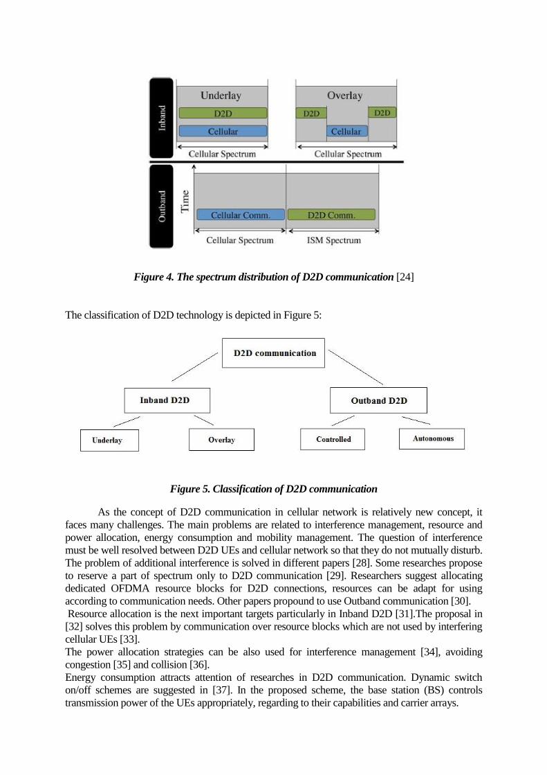
Figure 4. The spectrum distribution of D2D communication [24]
The classification of D2D technology is depicted in Figure 5:
Figure 5. Classification of D2D communication
As the concept of D2D communication in cellular network is relatively new concept, it
faces many challenges. The main problems are related to interference management, resource and
power allocation, energy consumption and mobility management. The question of interference
must be well resolved between D2D UEs and cellular network so that they do not mutually disturb.
The problem of additional interference is solved in different papers [28]. Some researches propose
to reserve a part of spectrum only to D2D communication [29]. Researchers suggest allocating
dedicated OFDMA resource blocks for D2D connections, resources can be adapt for using
according to communication needs. Other papers propound to use Outband communication [30].
Resource allocation is the next important targets particularly in Inband D2D [31].The proposal in
[32] solves this problem by communication over resource blocks which are not used by interfering
cellular UEs [33].
The power allocation strategies can be also used for interference management [34], avoiding
congestion [35] and collision [36].
Energy consumption attracts attention of researches in D2D communication. Dynamic switch
on/off schemes are suggested in [37]. In the proposed scheme, the base station (BS) controls
transmission power of the UEs appropriately, regarding to their capabilities and carrier arrays.
Another surveyed issue in D2D communication is mobility. Some works are focused on energy
and bandwidth efficiency of moving UEs [38]. When it is required to extend the lifetime of UE's
battery and to reduce the power consumption, the selection of the best route should occur in routing
algorithms. If a route is chosen for low-power transmission, that bandwidth could be dedicated. A
high power transmission can enhance bandwidth efficiency, but this does not apply when there is
interference in the system. In [39], the authors propose to allocate each UE a different transmission
range at each time slot.
3. Simulation scenario, deployment and models
In this chapter, the assumptions of simulation in Matlab are presented. The model of 3-site
clustered eNodeB pattern [40] is demonstrated. Then, the amount of UEs, their layout and
deployment of SCeNBs [9] are defined. Furthermore, two scenarios of simulation are
described. Also the model for movement of UEs, PRWMM model is represented. Last, the
algorithm used for decision on D2D communication is described.
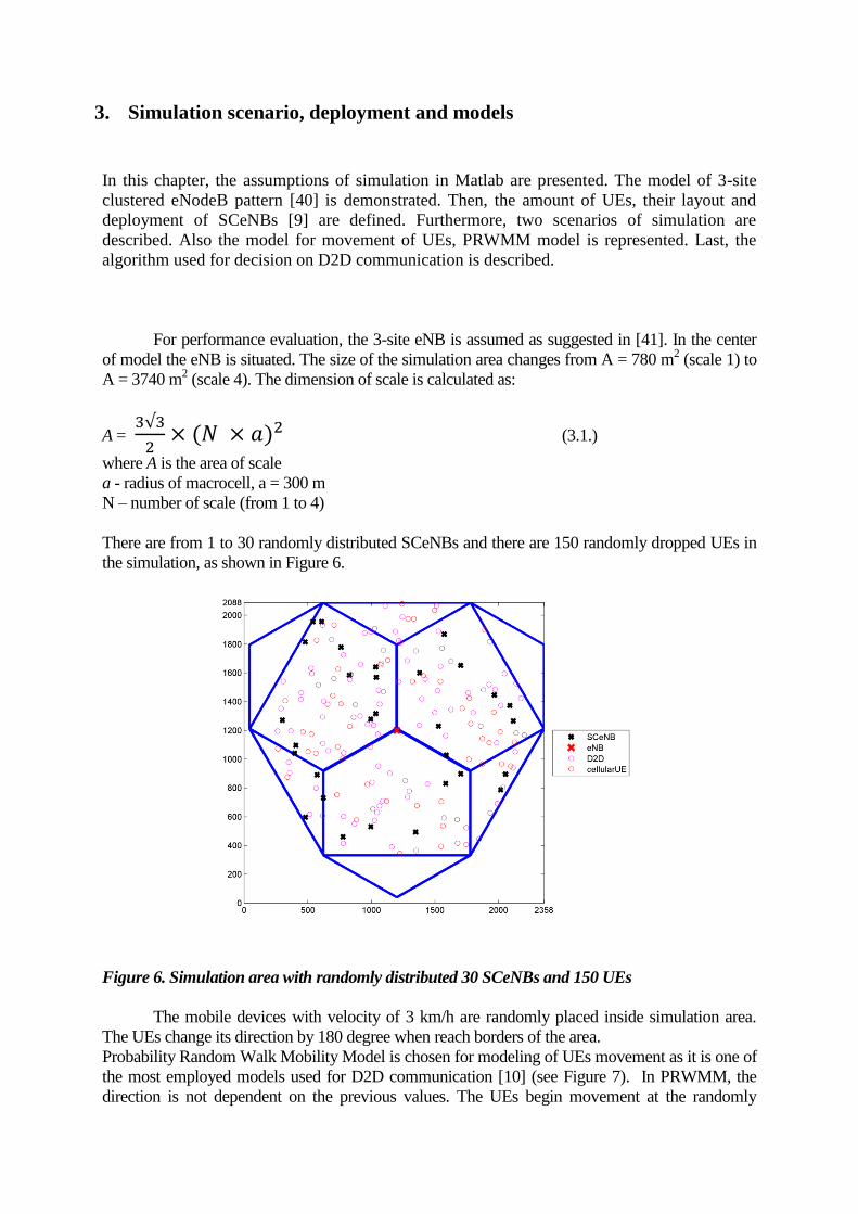
For performance evaluation, the 3-site eNB is assumed as suggested in [41]. In the center
of model the eNB is situated. The size of the simulation area changes from A = 780 m2 (scale 1) to
A = 3740 m2 (scale 4). The dimension of scale is calculated as:
A =
(3.1.)
where A is the area of scale
a - radius of macrocell, a = 300 m
N – number of scale (from 1 to 4)
There are from 1 to 30 randomly distributed SCeNBs and there are 150 randomly dropped UEs in
the simulation, as shown in Figure 6.
Figure 6. Simulation area with randomly distributed 30 SCeNBs and 150 UEs
The mobile devices with velocity of 3 km/h are randomly placed inside simulation area.
The UEs change its direction by 180 degree when reach borders of the area.
Probability Random Walk Mobility Model is chosen for modeling of UEs movement as it is one of
the most employed models used for D2D communication [10] (see Figure 7). In PRWMM, the
direction is not dependent on the previous values. The UEs begin movement at the randomly
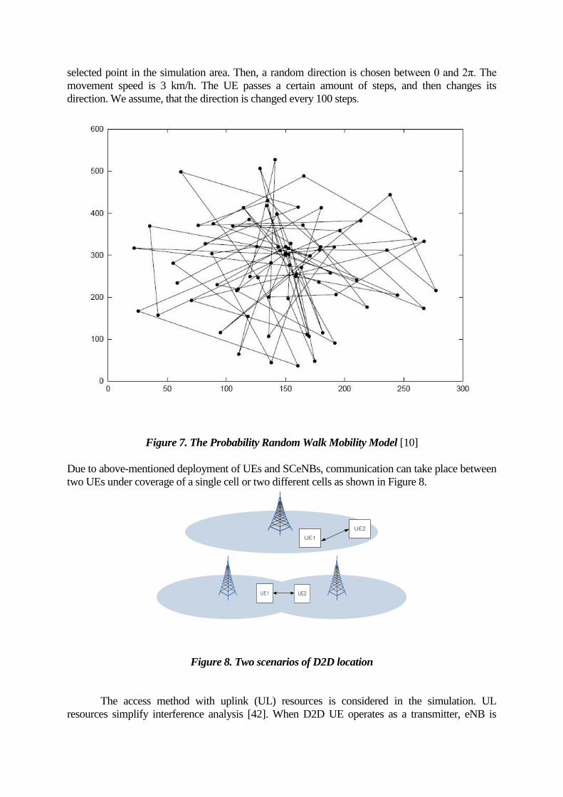
selected point in the simulation area. Then, a random direction is chosen between 0 and 2π. The
movement speed is 3 km/h. The UE passes a certain amount of steps, and then changes its
direction. We assume, that the direction is changed every 100 steps.
Figure 7. The Probability Random Walk Mobility Model [10]
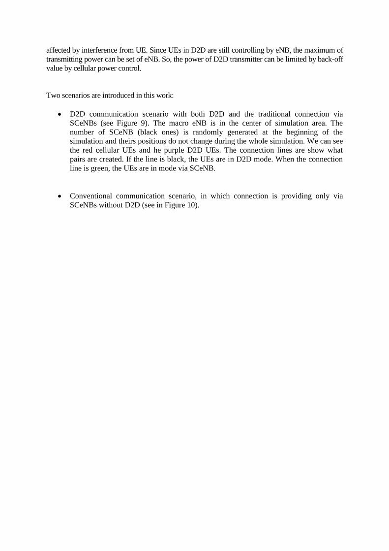
Due to above-mentioned deployment of UEs and SCeNBs, communication can take place between
two UEs under coverage of a single cell or two different cells as shown in Figure 8.
UE1
UE2
UE1 UE2
Figure 8. Two scenarios of D2D location
The access method with uplink (UL) resources is considered in the simulation. UL
resources simplify interference analysis [42]. When D2D UE operates as a transmitter, eNB is
affected by interference from UE. Since UEs in D2D are still controlling by eNB, the maximum of
transmitting power can be set of eNB. So, the power of D2D transmitter can be limited by back-off
value by cellular power control.
Two scenarios are introduced in this work:
D2D communication scenario with both D2D and the traditional connection via
SCeNBs (see Figure 9). The macro eNB is in the center of simulation area. The
number of SCeNB (black ones) is randomly generated at the beginning of the
simulation and theirs positions do not change during the whole simulation. We can see
the red cellular UEs and he purple D2D UEs. The connection lines are show what
pairs are created. If the line is black, the UEs are in D2D mode. When the connection
line is green, the UEs are in mode via SCeNB.
Conventional communication scenario, in which connection is providing only via
SCeNBs without D2D (see in Figure 10).

Figure 9. D2D communication scenario
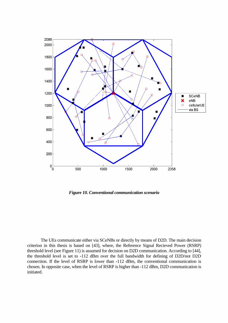
Figure 10. Conventional communication scenario
The UEs communicate either via SCeNBs or directly by means of D2D. The main decision
criterion in this thesis is based on [43], where, the Reference Signal Recieved Power (RSRP)
threshold level (see Figure 11) is assumed for decision on D2D communication. According to [44],
the threshold level is set to -112 dBm over the full bandwidth for defining of D2D/not D2D
connection. If the level of RSRP is lower than -112 dBm, the conventional communication is
chosen. In opposite case, when the level of RSRP is higher than -112 dBm, D2D communication is
initiated.

Figure 11. Decision for D2D or non D2D scenario [44]
For calculation of the RSRP, it is necessary to compute distance between UEs and to detect Path
Loss model [45], which is defined as:
[ dB ] (2.1.)
where d is the distance between UEs [46].
RSRP is calculated as:
[ dBm ] (2.2.)
where PTx is the transmit power of the UE, as we focus on uplink communication [46, pp. 37] and
in this thesis, PTx = 23 dBm, PL is the path loss, computed according to (2.1) and
Sh is shadowing, Sh = 7dBm.
In this thesis, is necessary to calculate the following values as Noise Power (NP) and Signal
Noise Ratio (SINR). SINR is used to calculate capacity. Capacity is crucial metrics in the
evaluation of results the whole simulation. It should be noted that all necessary recalculates from
W to dBm are allowed in final calculations in simulation.
According to [47], the noise power is defined as:
[ dBW ] (2.3.)
where
k – Boltzmann constant, k = 1.38 [ J/K ]
T0 – absolute temperature, T0 = 290 [ K ]
BW – system bandwidth, BW = 10 [ MHz ]
SINR is defined as [48]:
SINR [dBm] (2.4.)
where
S – reference signal received power (RSRP) [dBm]
NP–noise power, recalculated to dBm
I – interference, I is the set of all interfering transmitters TX [ dBm ]
The main performance metric in this thesis is capacity. Shannon Capacity is calculating as [49]:
[ bit/s ] (2.5.)
where
BW – bandwidth [MHz], BW = bw/n, where bw = 10 [MHz], n = number of UEs
SINR – signal to interference plus noise ratio [dBm]

4. Simulation results
In this chapter the table of simulation assumptions is introduced. And the results of the simulation
are evaluated.
In this thesis majority of values for computations are taken from document 3GPP TR 36.843
which has been produced by the 3rd
Generation Partnership Project (3GPP).
Parameter Value
Tx Power 23 dBm
RSRP -112 dBm
UE velocity 3 km/h
Simulation time 1000 s
Number of steps 100 steps
Number of UEs 150
Size of scale 1-4
Carrier frequency 2 GHz
System Bandwidth (uplink) for FDD 10MHz
Path loss model Indoor femto channel model [26c]
Network layout 3 macrocell, 30 small cells
Minimum distance between UE and eNodeB 35m
Minimum distance between UEs 3m
Shadowing 7 dBm
Table 4. Main simulation assumption [40]
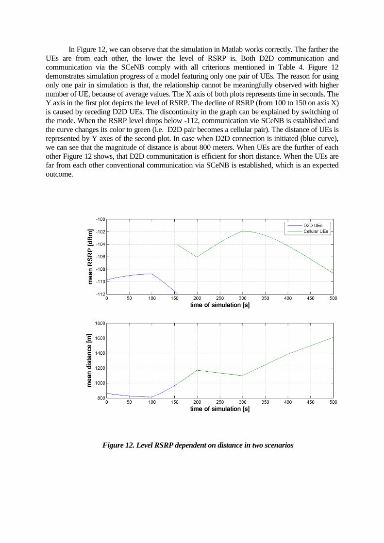
In Figure 12, we can observe that the simulation in Matlab works correctly. The farther the
UEs are from each other, the lower the level of RSRP is. Both D2D communication and
communication via the SCeNB comply with all criterions mentioned in Table 4. Figure 12
demonstrates simulation progress of a model featuring only one pair of UEs. The reason for using
only one pair in simulation is that, the relationship cannot be meaningfully observed with higher
number of UE, because of average values. The X axis of both plots represents time in seconds. The
Y axis in the first plot depicts the level of RSRP. The decline of RSRP (from 100 to 150 on axis X)
is caused by receding D2D UEs. The discontinuity in the graph can be explained by switching of
the mode. When the RSRP level drops below -112, communication vie SCeNB is established and
the curve changes its color to green (i.e. D2D pair becomes a cellular pair). The distance of UEs is
represented by Y axes of the second plot. In case when D2D connection is initiated (blue curve),
we can see that the magnitude of distance is about 800 meters. When UEs are the further of each
other Figure 12 shows, that D2D communication is efficient for short distance. When the UEs are
far from each other conventional communication via SCeNB is established, which is an expected
outcome.
Figure 12. Level RSRP dependent on distance in two scenarios
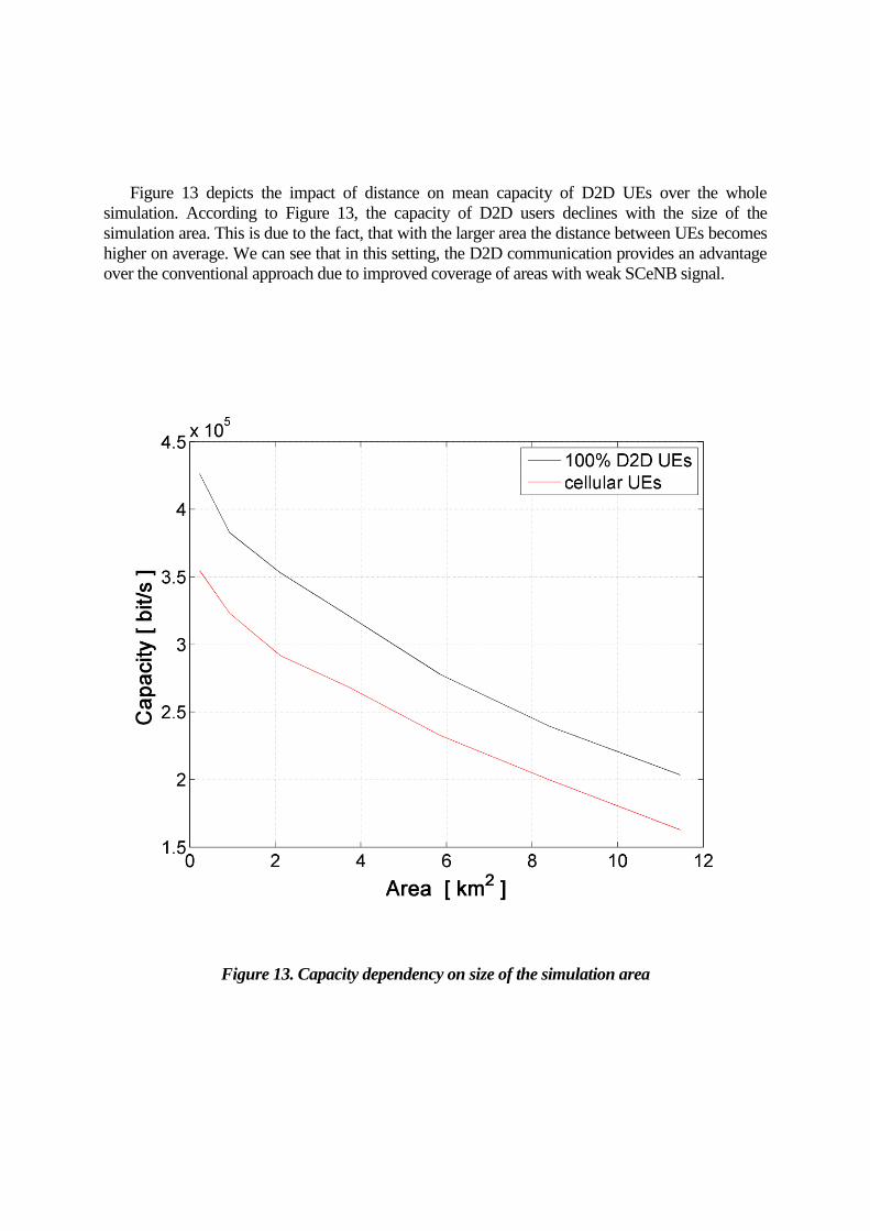
Figure 13 depicts the impact of distance on mean capacity of D2D UEs over the whole
simulation. According to Figure 13, the capacity of D2D users declines with the size of the
simulation area. This is due to the fact, that with the larger area the distance between UEs becomes
higher on average. We can see that in this setting, the D2D communication provides an advantage
over the conventional approach due to improved coverage of areas with weak SCeNB signal.
Figure 13. Capacity dependency on size of the simulation area
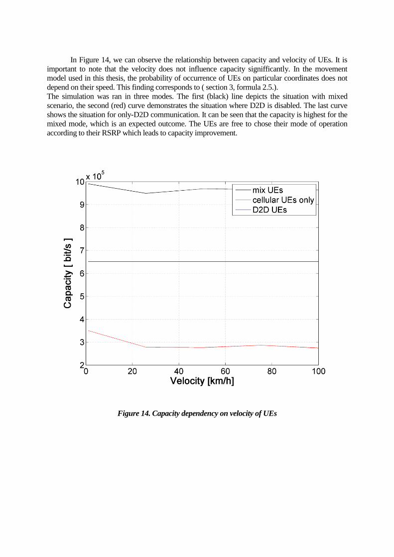
In Figure 14, we can observe the relationship between capacity and velocity of UEs. It is
important to note that the velocity does not influence capacity signifficantly. In the movement
model used in this thesis, the probability of occurrence of UEs on particular coordinates does not
depend on their speed. This finding corresponds to ( section 3, formula 2.5.).
The simulation was ran in three modes. The first (black) line depicts the situation with mixed
scenario, the second (red) curve demonstrates the situation where D2D is disabled. The last curve
shows the situation for only-D2D communication. It can be seen that the capacity is highest for the
mixed mode, which is an expected outcome. The UEs are free to chose their mode of operation
according to their RSRP which leads to capacity improvement.
Figure 14. Capacity dependency on velocity of UEs

In Figure 15, the decrease of capacity depending on number of UEs is shown. The capacity
drops in all cases. As can be seen, the rate of capacity decrease in mixed scenario is slower than the
rate of capacity decrease in other cases.
Figure 15. Capacity dependency on number of users in two scenarios
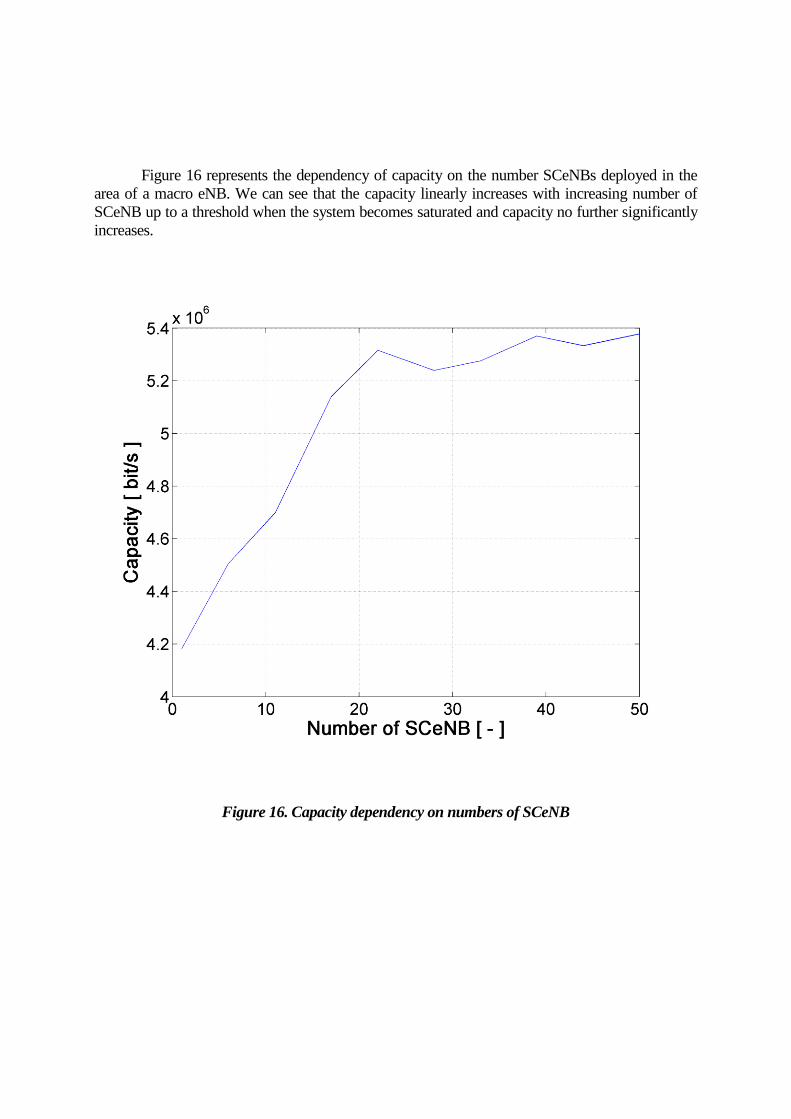
Figure 16 represents the dependency of capacity on the number SCeNBs deployed in the
area of a macro eNB. We can see that the capacity linearly increases with increasing number of
SCeNB up to a threshold when the system becomes saturated and capacity no further significantly
increases.
Figure 16. Capacity dependency on numbers of SCeNB
Conclusion and future works
In this bachelor thesis, we have studied D2D communication and potential suitability of D2D
in heterogeneous networks with SCeNB.
We have conducted a number of experiments, for example, the performance of the model
under the change of number of users, area and user’s speed was tested. The experiments have
proven validity of the model. We have verified that the capacity decreases both with
increasing number of users and with increasing area of the model. This phenomenon is less
significant when the D2D model is employed. We investigate the influence of added SCeNB.
The increase od SCeNB number has significantly improved the average capacity.
We have implemented a simulation environment based on the PRWMM model and have
conducted several experiments to demonstrate the properties of the D2D technology. We have
shown that the model complies with our expectations and with practical experience [8]. The
implementation of the model in Matlab is robust and modular; it can be easily extended for
new scenarios. Albeit some limitations, which will be handled in future works, exist, the
current model can successfully predict behavior of the system in various situations (varying
number of users, different simulation area and number of SCeNBs). It enables us to calculate
requested metrics, and to evaluate results of simulated UEs behavior in different modes.
This thesis would be an introduction work in field of direct communication. The topic is very
broad and would have to be covered by deeper research. The room for improvement can be
mainly seen in following subtopics:
a more complex model of interference should be implemented and experimentally
verified
more mobility models could be implemented and compared in terms of the influence
of mobility model on the behavior of the whole system

References
[1] 3GPP LTE web page: http://www.3gpp.org/technologies/keywords-acronyms/98-lte
[2] Hoikkanen A., “Economics of 3G Long-Term Evolution: the Business Case for the Mobile
Operator,“ WOCN 07, 2007
[3] Duan L., Huang J., Walrand J., „Economic Analysis of 4G Upgrade Timing,“ IEEE. 2015
[4] 3GPP Project web page: http://www.3gpp.org/about-3gpp
[5] Pirinen, P., „A Brief Overview of 5G Research Activities,“ 5GU, 2014
[6] 3GPP, “Vocabulary for 3GPP Specifications,” TR 121 905 V12.0.0, 2014
[7] Mukherjee A. „Macro-Small Cell Grouping in Dual Connectivity LTE-B Networks with Non-
ideal Backhaul,“ IEEE, 2014
[8] Vanganuru K., Ferrante S., Sternberg G., „System capacity and coverage of a cellular network with
D2D mobile relays,“ MILCOM 2012
[9] Mach P., Becvar Z., “Cloud-aware power control for cloud-enabled small cells,“ GC Wkshps,
2014
[10] T. Camp T., Boleng J., Davies V., „A Survey of Mobility Models for Ad Hoc Network
Research,“ IEEE, 2002, pp. 5-7
[11] Ka Lok Man, Jieming Ma, Jeong, T.T., Chi-Un Lei , „Design, analysis, tools and
applications for programmable high-speed and power-aware 4G processors,“ ISOCC, 2011
[12] Jeanette Wannstrom, „LTE-Advanced,“ 3GPP, 2013
[13] Korowajczuk L., “LTE, WiMAX and WLAN Network Design, Optimization and
Performance Analysis,” IEEE, 2011, pp.410-411
[14] Berardinelli G., Sorensen T., Mogensen P., Pajukoski K., „SVD-Based vs. Release 8
Codebooks for Single User MIMO LTE-A Uplink,“ , IEEE, 2010,pp. 5
[15] Banani S., Adve R., “Analyzing the Impact of Inter Cooperation Region Interference in Coordinated
Multi-Point Uplink Networks, ” IEEE, 2015
[16] 3GPP, "Evolved Universal Terrestrial Radio Access Network (EUTRAN); X2 general aspects and
principles," TS 36.420 V8.0.0 (2007-12)
[17] 3GPP, “"Non-Access-Stratum (NAS) protocol for Evolved Packet System (EPS),” TS
24.301
[18] 3GPP, "Evolved Packet System (EPS); Mobility Management Entity (MME) and Serving
GPRS Support Node (SGSN) related interfaces based on Diameter protocol," TS 29.272. , 2009
[19] Jain R.K., Katiyar S., Agrawal N. K., „Hierarchical Cellular Structures in High-Capacity
Cellular Communication Systems ,“ IEEE, 2011, pp. 3-4
[20] Kim J., Lee J., Kim Jh., “M2M Service Platforms: Survey, Issues, and Enabling Technologies,”
IEEE, 2013
[21] Zheng Y., Blostein S., “Cooperative uplink cellular systems with multi-antenna relays and
heterogeneous users,” IEEE, 2013
[22] Peltotalo J., Hariu J., Jantunen A., Saukko M., “Peer-to-Peer Streaming Technology Survey,” ICN.
2008
[23] Broxton, T. ; Interian, Y. ; Vaver, J. ; Wattenhofer, M., „Catching a Viral Video,“ IEEE
2010
[24] Asadi A., Wang Q., Mancuso V., “A Survey on Device-to-Device Communication in
Cellular Networks,” IEEE, 2014
[25]Yang F., Zhang Xi, “Efficient packet detection for D2D power-saving communications
over mobile wireless cellular networks“, GLOBECOM, 2014
[26] Bae J., An T., Kym Y., Ryu C., „Analysis of digital load cell using 2.4GHz band’s Zig-
Bee,“ ICIEA, 2008
[27] Bluetooth official web page: https://www.bluetooth.org/en-us
[28] T. Peng, Q. Lu, H. Wang, S. Xu, and W. Wang, “Interference avoidance mechanisms in the
hybrid cellular and device-to-device systems,” IEEE, 2009, pp. 617–621.
[29] Y. Pei and Y.-C. Liang, “Resource allocation for device-to-device communication
overlaying two-way cellular networks,” IEEE, 2013.
[30] N. K. Pratas and P. Popovski, “Low-rate machine-type communication via wireless
Device-to-Device (D2D) links,” arXiv, 2013
[31] S. C. Spinella, G. Araniti, A. Iera, and A. Molinaro, “Integration of ad-hoc networks with
infrastructured systems for multicast services provisioning,” IEEE, 2009, pp. 1–6.
[32] Samdanis, K., Shrivastava, R. , Prasad, A., Rost, P. “Virtual Cells: Enhancing the Resource
Allocation Efficiency for TD-LTE,“ 2014
[33] Ku, G. ; Walsh, J. „Resource Allocation and Link Adaptation in LTE and LTE Advanced: A
Tutorial,“ IEEE, 2014
[34] Zainaldin, A., Halabian, H. ; Lambadaris, I. „Optimal resource allocation in LTE-Advanced
network using hybrid Cooperative Relaying and network coding,“ IEEE, 2013
[35] B. Kaufman and B. Aazhang, “Cellular networks with an overlaid device to device network,”
Asilomar Conf. Signals, Syst. Comput., 2008, pp. 1537–1541.
[36] Mahfoudi, M., El Bekkali, M., Mazer, S., El Ghazi, M., „LTE network capacity analysis to
avoid congestion for real time traffic,“ IWCMC, 2014
[37] Kwan, R., Leung, C., „On Collision Probabilities in Frequency-Domain Scheduling for LTE
Cellular Networks, “IEEE, 2011
[38] Jianjun Sun, Hao Jin, Yong Li, Xiaodong Ji, „Minimizing energy consumption based on
capabilities of users for carrier aggregation in LTE-Advanced systems,“ ICST, 2013
[39] Wu D., Hou L., Cai Y., Qingyang Hu R., Qian Y., „The role of mobility for D2D
communications in LTE-Advanced networks: energy vs. bandwidth efficiency,“ IEEE, 2014
[40] 3GPP, “Study on LTE device to device proximity services,” TR 36.843 V12.0.0, 2014, pp. 37
[41] 3GPP, “Study on LTE device to device proximity services,” TR 36.843 V12.0.0, 2014, pp. 18
[42] Doppler, K., Rinne, M., Wijting, C., Ribeiro, C., “Device-to-Device Communication as an
Underlay to LTE-Advanced Networks,“ IEEE, 2009
[43] 3GPP, “Study on LTE device to device proximity services,” TR 36.843 V12.0.0, 2014, pp.37
[44] 3GPP, „Decision metric for D2D communication, “R1-142294, 2014, pp. 2-3
[45] 3GPP TSG-RAN WG173 , ”Aspects of the decision process for D2D communication,” R1-
132322, 2014
[46] 3GPP, “Study on LTE device to device proximity services,” TR 36.843 V12.0.0, 2014
[47] Wong K., “Fundamentals of Wireless Communication Engineering Technologies,” Wiley,
2011, pp.75
[48] Haenggi, M., Andrews, J., Baccelli, F., Dousse, O. , “Stochastic Geometry and Random
Graphs for the Analysis and Design of Wireless Networks,” IEEE, 2009
[49] Shannon C.E., “Communication in the Presence of Noise, “2002, pp. 452


![Septum feed revisited - ok1dfc.com · dish antenna. Franta, OK1CA, developed and Zdenek, OK1DFC [1], described septum feed for Franta, OK1CA, developed and Zdenek, OK1DFC [1], described](https://static.fdocuments.net/doc/165x107/5b63a4ea7f8b9a0e428c305e/septum-feed-revisited-dish-antenna-franta-ok1ca-developed-and-zdenek-ok1dfc.jpg)