FACTS – powerful systems for flexible power transmission · above the surge impedance loading...
14
4 ABB Review 5/1999 emand for electrical energy contin- ues to grow steadily, and is particularly strong in those countries on the threshold of industrialization. For various reasons, electricity grid upgrades, and especially the construction of new transmission lines, cannot keep pace with the growing power plant capacity and energy demand. Finding suitable right-of-ways is particu- larly difficult in the industrialized countries, and gaining the necessary approval is more time-consuming than ever. In addi- tion, power line construction ties up in- vestment capital that could be used for other projects. Due to this situation, operators are looking for ways to utilize the existing power lines more efficiently. Two areas re- quire special attention. In the first place, there is a need to improve the transient and steady state stability of long lines. This is because some power lines cannot be loaded to anywhere near their natural load rating – let alone the thermal limit rat- ing – due to relatively low stability limits. Action taken in support of stability during and after line faults can improve system reliability just as much as by adding one or more lines. Secondly, the load flow needs to be improved in closely intermeshed net- works as the ‘natural’ load flow resulting from the load conditions and existing line impedances is not necessarily the load flow that will minimize the transmission losses. Another aspect is flexibility: a deregu- lated energy market requires flexible power system operation to ensure that the electricity supply contracts can be ful- filled. Flexible AC Transmission Systems (FACTS) have all the capability grid opera- tors need to meet the challenges pre- sented by the fast-changing energy mar- ket. Power transfer limits Power flow over a transmission system is limited by one or more of the following net- work characteristics: • Stability limits • Thermal limits • Voltage limits • Loop flows Technically, limitations on power transfer can always be removed by adding new transmission and/or generation capacity. FACTS are designed to remove such limitations and meet operators’ goals without having to undertake major system additions. Given the nature of power elec- tronics equipment, FACTS solutions will be justified wherever the application re- quires one or more of the following attributes: • Rapid response • Frequent variation in output • Smoothly adjustable output Flexible AC Transmission Systems (FACTS) The term ‘FACTS’ covers all of the power electronics based systems used in AC power transmission. The main systems are: • Static var compensator (SVC) • Fixed and thyristor-controlled series capacitor (TCSC) • Phase-shifting transformer (PST) and assisted PST (APST) • Synchronous static compensator (STATCOM) • Synchronous static series compen- sator (SSSC) • Universal power flow controller (UPFC) FACTS – powerful systems for flexible power transmission Rolf Grünbaum Mojtaba Noroozian Björn Thorvaldsson ABB Power Systems The fast-changing energy market has brought the operators of high- voltage transmission systems a combination of fresh opportunities and new challenges. The latter stem mainly from the strong increase in inter- utility power transfers, the effects of deregulation, and economic and eco- logical constraints on the building of new transmission facilities. Today’s AC power transmission networks are not designed for easy voltage and power flow control in a deregulated market, and steady-state control problems as well as dynamic stability problems are the result. The devel- opment of Flexible AC Transmission Systems, or FACTS, based on high- power electronics, offers a powerful new means of meeting the chal- lenges. D F A C T S
Transcript of FACTS – powerful systems for flexible power transmission · above the surge impedance loading...
4 A B B R e v i e w 5 / 1 9 9 9
emand for electrical energy contin-
ues to grow steadily, and is particularly
strong in those countries on the threshold
of industrialization. For various reasons,
electricity grid upgrades, and especially
the construction of new transmission
lines, cannot keep pace with the growing
power plant capacity and energy demand.
Finding suitable right-of-ways is particu-
larly difficult in the industrialized countries,
and gaining the necessary approval is
more time-consuming than ever. In addi-
tion, power line construction ties up in-
vestment capital that could be used for
other projects.
Due to this situation, operators are
looking for ways to utilize the existing
power lines more efficiently. Two areas re-
quire special attention. In the first place,
there is a need to improve the transient
and steady state stability of long lines.
This is because some power lines cannot
be loaded to anywhere near their natural
load rating – let alone the thermal limit rat-
ing – due to relatively low stability limits.
Action taken in support of stability during
and after line faults can improve system
reliability just as much as by adding one or
more lines. Secondly, the load flow needs
to be improved in closely intermeshed net-
works as the ‘natural’ load flow resulting
from the load conditions and existing line
impedances is not necessarily the load
flow that will minimize the transmission
losses.
Another aspect is flexibility: a deregu-
lated energy market requires flexible
power system operation to ensure that
the electricity supply contracts can be ful-
filled.
Flexible AC Transmission Systems
(FACTS) have all the capability grid opera-
tors need to meet the challenges pre-
sented by the fast-changing energy mar-
ket.
Power transfer limits
Power flow over a transmission system is
limited by one or more of the following net-
work characteristics:
• Stability limits
• Thermal limits
• Voltage limits
• Loop flows
Technically, limitations on power transfer
can always be removed by adding new
transmission and/or generation capacity.
FACTS are designed to remove such
limitations and meet operators’ goals
without having to undertake major system
additions. Given the nature of power elec-
tronics equipment, FACTS solutions will
be justified wherever the application re-
quires one or more of the following
attributes:
• Rapid response
• Frequent variation in output
• Smoothly adjustable output
Flexible AC Transmission Systems
(FACTS)
The term ‘FACTS’ covers all of the power
electronics based systems used in AC
power transmission.
The main systems are:
• Static var compensator (SVC)
• Fixed and thyristor-controlled series
capacitor (TCSC)
• Phase-shifting transformer (PST) and
assisted PST (APST)
• Synchronous static compensator
(STATCOM)
• Synchronous static series compen-
sator (SSSC)
• Universal power flow controller (UPFC)
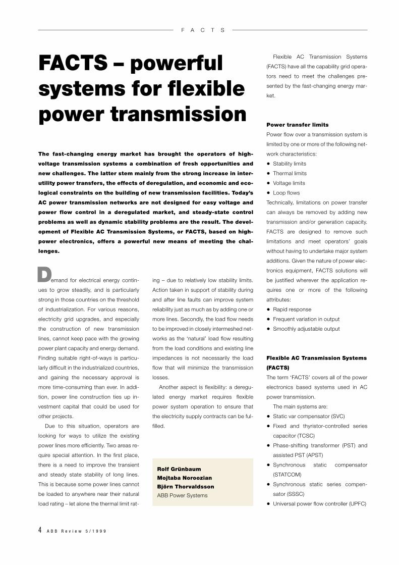
FACTS – powerfulsystems for flexible power transmission
Rolf Grünbaum
Mojtaba Noroozian
Björn Thorvaldsson
ABB Power Systems
The fast-changing energy market has brought the operators of high-
voltage transmission systems a combination of fresh opportunities and
new challenges. The latter stem mainly from the strong increase in inter-
utility power transfers, the effects of deregulation, and economic and eco-
logical constraints on the building of new transmission facilities. Today’s
AC power transmission networks are not designed for easy voltage and
power flow control in a deregulated market, and steady-state control
problems as well as dynamic stability problems are the result. The devel-
opment of Flexible AC Transmission Systems, or FACTS, based on high-
power electronics, offers a powerful new means of meeting the chal-
lenges.
D
F A C T S
A B B R e v i e w 5 / 1 9 9 9 5
Static var compensator (SVC)
Over the years static var compensators of
many different designs have been built.
Nevertheless, the majority of them have
similar controllable elements. The most
common ones are:
• Thyristor-controlled reactor (TCR)
• Thyristor-switched capacitor (TSC)
• Thyristor-switched reactor (TSR)
• Mechanically switched capacitor (MSC)
Principle of operation
In the case of the TCR a fixed reactor,
typically an air-core type, is connected in
series with a bidirectional thyristor valve.
The fundamental frequency current is var-
ied by phase control of the thyristor valve.
A TSC comprises a capacitor in series
with a bidirectional thyristor valve and a
damping reactor. The function of the
thyristor switch is to connect or discon-
nect the capacitor for an integral number
of half-cycles of the applied voltage. The
capacitor is not phase-controlled, being
simply on or off. The reactor in the TSC
circuit serves to limit current under abnor-
mal conditions as well as to tune the cir-
cuit to a desired frequency.
The impedances of the reactors and ca-
pacitors and of the power transformer de-
fine the operating range of the SVC. The
corresponding V–I diagram has two differ-
ent operating regions. Inside the control
range, voltage is controllable with an accu-
racy set by the slope. Outside the control
range the characteristic is that of a capac-
itive reactance for low voltages, and that of
a constant current for high voltages. The
low-voltage performance can easily be im-
proved by adding an extra TSC bank (for
use under low-voltage conditions only).
The TSR is a TCR without phase con-
trol of the current, being switched in or out
like a TSC. The advantage of this device
over the TCR is that no harmonic currents
are generated.
The MSC is a tuned branch comprising
a capacitor bank and a reactor. It is de-
signed to be switched no more than a few
times a day as the switching is performed
by circuit-breakers. The purpose of the
MSC is to meet steady-state reactive
power demand.
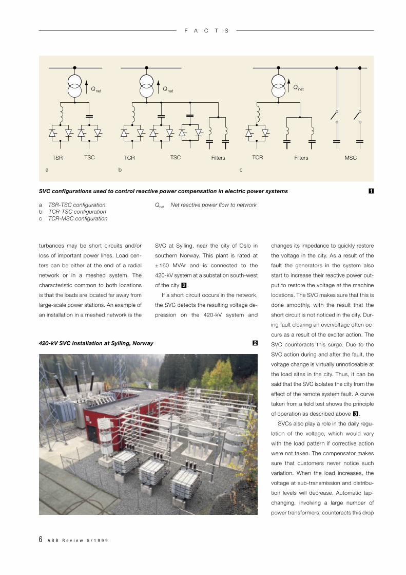
SVC configurations
Controlled reactive power compensation
is usually achieved in electric power sys-
tems by means of the SVC configurations
shown in .
SVC applications
SVCs are installed to perform the following
functions:
• Dynamic voltage stabilization: in-
creased power transfer capability, re-
duced voltage variation
1
• Synchronous stability improvements:
increased transient stability, improved
power system damping
• Dynamic load balancing
• Steady-state voltage support
Typically, SVCs are rated such that they
are able to vary the system voltage by at
least ± 5 %. This means that the dynamic
operating range is normally about 10 % to
20 % of the short-circuit power at the
point of common connection (PCC). Three
different locations are suitable for the SVC.
One is close to major load centers, such
as large urban areas, another is in critical
substations, normally in remote grid loca-
tions, and the third is at the infeeds to
large industrial or traction loads.
Location 1: Major load centers
The usual reason for installing SVCs in
load centers is to mitigate the effect of grid
disturbances on sensitive loads. The dis-
F A C T S
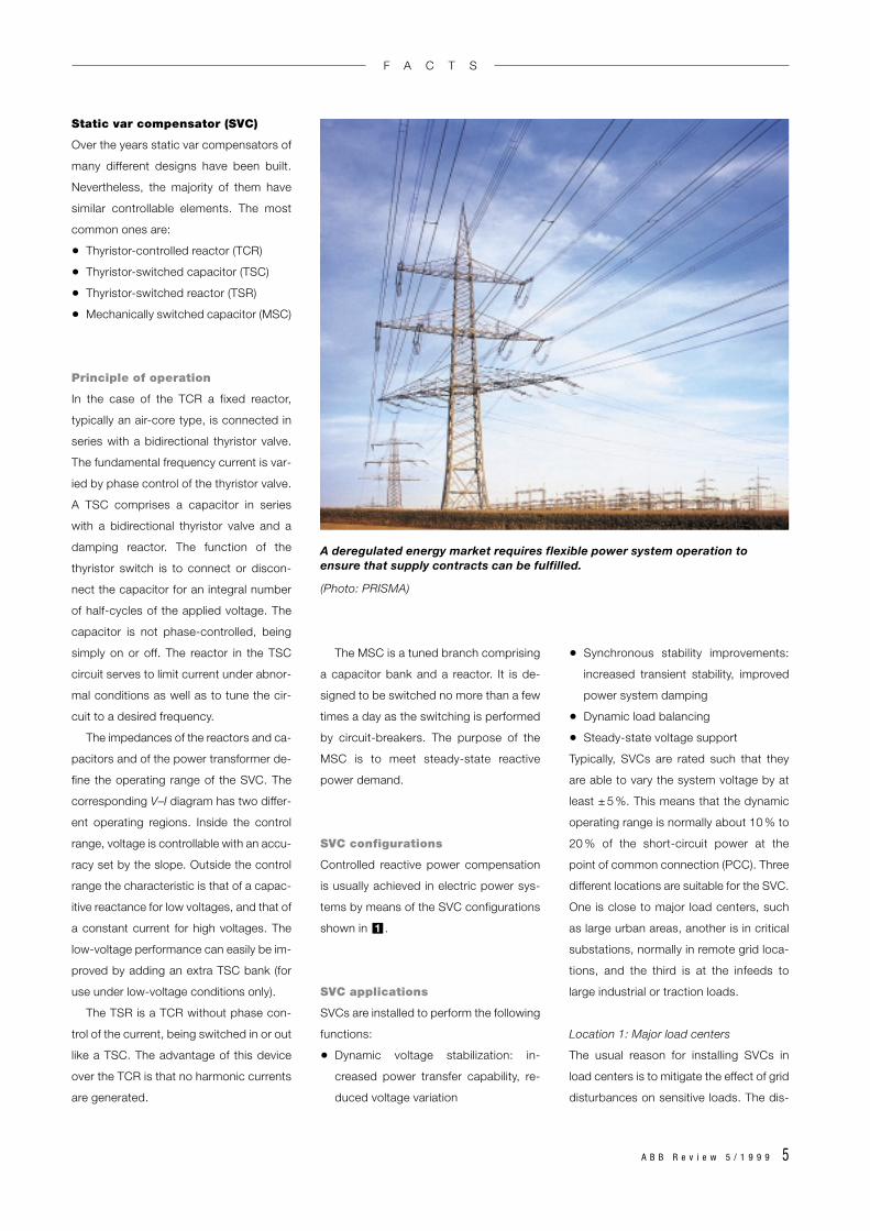
A deregulated energy market requires flexible power system operation toensure that supply contracts can be fulfilled.
(Photo: PRISMA)
6 A B B R e v i e w 5 / 1 9 9 9
turbances may be short circuits and/or
loss of important power lines. Load cen-
ters can be either at the end of a radial
network or in a meshed system. The
characteristic common to both locations
is that the loads are located far away from
large-scale power stations. An example of
an installation in a meshed network is the
SVC at Sylling, near the city of Oslo in
southern Norway. This plant is rated at
± 160 MVAr and is connected to the
420-kV system at a substation south-west
of the city .
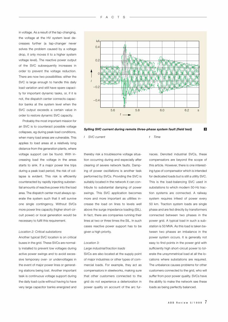
If a short circuit occurs in the network,
the SVC detects the resulting voltage de-
pression on the 420-kV system and
2
changes its impedance to quickly restore
the voltage in the city. As a result of the
fault the generators in the system also
start to increase their reactive power out-
put to restore the voltage at the machine
locations. The SVC makes sure that this is
done smoothly, with the result that the
short circuit is not noticed in the city. Dur-
ing fault clearing an overvoltage often oc-
curs as a result of the exciter action. The
SVC counteracts this surge. Due to the
SVC action during and after the fault, the
voltage change is virtually unnoticeable at
the load sites in the city. Thus, it can be
said that the SVC isolates the city from the
effect of the remote system fault. A curve
taken from a field test shows the principle
of operation as described above .
SVCs also play a role in the daily regu-
lation of the voltage, which would vary
with the load pattern if corrective action
were not taken. The compensator makes
sure that customers never notice such
variation. When the load increases, the
voltage at sub-transmission and distribu-
tion levels will decrease. Automatic tap-
changing, involving a large number of
power transformers, counteracts this drop
3
FiltersTCR TSCTSC
Qnet
TSR
Qnet
a b c
Filters MSC
Qnet
TCR
SVC configurations used to control reactive power compensation in electric power systems
a TSR-TSC configuration Qnet Net reactive power flow to networkb TCR-TSC configurationc TCR-MSC configuration
1
420-kV SVC installation at Sylling, Norway 2
F A C T S
A B B R e v i e w 5 / 1 9 9 9 7
in voltage. As a result of the tap-changing,
the voltage at the HV system level de-
creases further (a tap-changer never
solves the problem caused by a voltage
drop, it only moves it to a higher system
voltage level). The reactive power output
of the SVC subsequently increases in
order to prevent the voltage reduction.
There are now two possibilities: either the
SVC is large enough to handle this daily
load variation and still have spare capaci-
ty for important dynamic tasks, or, if it is
not, the dispatch center connects capac-
itor banks at the system level when the
SVC output exceeds a certain value in
order to restore dynamic SVC capacity.
Probably the most important mission for
an SVC is to counteract possible voltage
collapses, eg during peak load conditions,
when many load areas are vulnerable. This
applies to load areas at a relatively long
distance from the generation plants, where
voltage support can be found. With in-
creasing load the voltage in the areas
starts to sink. If a major power line trips
during a peak load period, the risk of col-
lapse is evident. This risk is efficiently
counteracted by rapidly injecting substan-
tial amounts of reactive power into the load
area. The dispatch center must always op-
erate the system such that it will survive
one single contingency. Without SVCs
more power line capacity (higher short-cir-
cuit power) or local generation would be
necessary to fulfil this requirement.
Location 2: Critical substations
Another typical SVC location is on critical
buses in the grid. These SVCs are normal-
ly installed to prevent low voltages during
active power swings and to avoid exces-
sive temporary over- or undervoltages in
the event of major power lines or generat-
ing stations being lost. Another important
task is continuous voltage support during
the daily load cycle without having to have
very large capacitor banks energized and
thereby risk a troublesome voltage situa-
tion occurring during and especially after
clearing of severe network faults. Damp-
ing of power oscillations is another task
performed by SVCs. Providing the SVC is
suitably located in the network it can con-
tribute to substantial damping of power
swings. This SVC application becomes
more and more important as utilities in-
crease the load on lines to levels well
above the surge impedance loading (SIL).
In fact, there are companies running their
lines at two or three times the SIL. In such
cases reactive power support has to be
given a high priority.
Location 3:
Large industrial/traction loads
SVCs are also located at the supply point
of major industries or other types of com-
mercial loads. For example, they act as
compensators in steelworks, making sure
that other customers connected to the
grid do not experience a deterioration in
power quality on account of the arc fur-
naces. Denoted industrial SVCs, these
compensators are beyond the scope of
this article. However, there is one interest-
ing type of compensator which is intended
for dedicated loads but is still a utility SVC.
This is the load-balancing SVC used in
substations to which modern 50-Hz trac-
tion systems are connected. A railway
system requires infeed of power every
50 km. Traction system loads are single
phase and are fed directly by transformers
connected between two phases in the
power grid. A typical load in such a sub-
station is 50 MVA. As this load is taken be-
tween two phases an imbalance in the
power system occurs. It is generally not
easy to find points in the power grid with
sufficiently high short-circuit power to tol-
erate the unsymmetrical load at all the lo-
cations where substations are required.
The unbalance causes problems for other
customers connected to the grid, who will
suffer from poor power quality. SVCs have
the ability to make the network see these
loads as being perfectly balanced.
5.6 5.8 6.0 6.2 s
0.4
kA
0.2
0
– 0.2
– 0.4
t
I
Sylling SVC current during remote three-phase system fault (field test)
I SVC current t Time
3
F A C T S
8 A B B R e v i e w 5 / 1 9 9 9
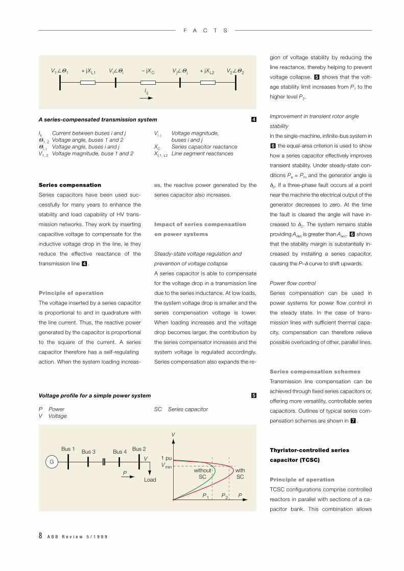
Series compensation
Series capacitors have been used suc-
cessfully for many years to enhance the
stability and load capability of HV trans-
mission networks. They work by inserting
capacitive voltage to compensate for the
inductive voltage drop in the line, ie they
reduce the effective reactance of the
transmission line .
Principle of operation
The voltage inserted by a series capacitor
is proportional to and in quadrature with
the line current. Thus, the reactive power
generated by the capacitor is proportional
to the square of the current. A series
capacitor therefore has a self-regulating
action. When the system loading increas-
4
es, the reactive power generated by the
series capacitor also increases.
Impact of series compensation
on power systems
Steady-state voltage regulation and
prevention of voltage collapse
A series capacitor is able to compensate
for the voltage drop in a transmission line
due to the series inductance. At low loads,
the system voltage drop is smaller and the
series compensation voltage is lower.
When loading increases and the voltage
drop becomes larger, the contribution by
the series compensator increases and the
system voltage is regulated accordingly.
Series compensation also expands the re-
gion of voltage stability by reducing the
line reactance, thereby helping to prevent
voltage collapse. shows that the volt-
age stability limit increases from P1 to the
higher level P2.
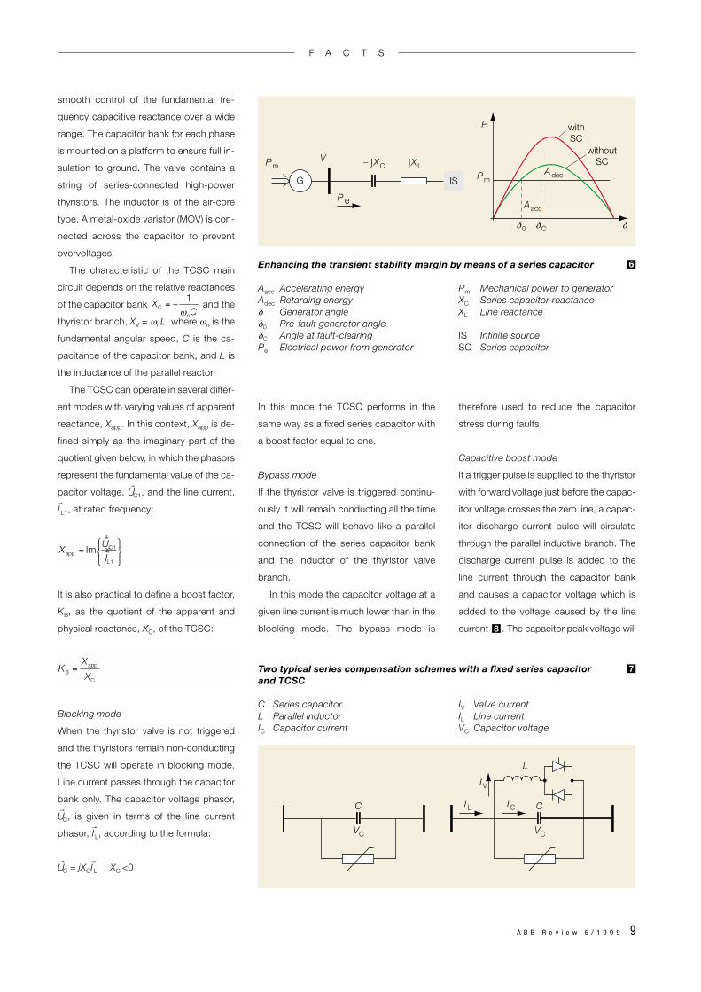
Improvement in transient rotor angle
stability
In the single-machine, infinite-bus system in
the equal-area criterion is used to show
how a series capacitor effectively improves
transient stability. Under steady-state con-
ditions Pe = Pm and the generator angle is
δ0. If a three-phase fault occurs at a point
near the machine the electrical output of the
generator decreases to zero. At the time
the fault is cleared the angle will have in-
creased to δC. The system remains stable
providing Adec is greater than Aacc. shows
that the stability margin is substantially in-
creased by installing a series capacitor,
causing the P–δ curve to shift upwards.
Power flow control
Series compensation can be used in
power systems for power flow control in
the steady state. In the case of trans-
mission lines with sufficient thermal capa-
city, compensation can therefore relieve
possible overloading of other, parallel lines.
Series compensation schemes
Transmission line compensation can be
achieved through fixed series capacitors or,
offering more versatility, controllable series
capacitors. Outlines of typical series com-
pensation schemes are shown in .
Thyristor-controlled series
capacitor (TCSC)
Principle of operation
TCSC configurations comprise controlled
reactors in parallel with sections of a ca-
pacitor bank. This combination allows
7
6
6
5
P1 P2 P
V
Vmin
V
P withoutSC
Bus 1 Bus 3 Bus 4 Bus 2
Load
1 pu
withSC
G
Voltage profile for a simple power system
P Power SC Series capacitorV Voltage
5
V i∠ iV1∠ 1 V2∠ 2– jXC+ jXL1 + jXL2
I ij
V j∠ j ΘΘΘΘ
A series-compensated transmission system
Iij Current between buses i and j Vi, j Voltage magnitude, Θ1, 2 Voltage angle, buses 1 and 2 buses i and jΘi, j Voltage angle, buses i and j XC Series capacitor reactanceV1, 2 Voltage magnitude, buse 1 and 2 XL1, L2 Line segment reactances
4
F A C T S
A B B R e v i e w 5 / 1 9 9 9 9
smooth control of the fundamental fre-
quency capacitive reactance over a wide
range. The capacitor bank for each phase
is mounted on a platform to ensure full in-
sulation to ground. The valve contains a
string of series-connected high-power
thyristors. The inductor is of the air-core
type. A metal-oxide varistor (MOV) is con-
nected across the capacitor to prevent
overvoltages.
The characteristic of the TCSC main
circuit depends on the relative reactances
of the capacitor bank , and the
thyristor branch, XV = ωnL, where ωn is the
fundamental angular speed, C is the ca-
pacitance of the capacitor bank, and L is
the inductance of the parallel reactor.
The TCSC can operate in several differ-
ent modes with varying values of apparent
reactance, Xapp. In this context, Xapp is de-
fined simply as the imaginary part of the
quotient given below, in which the phasors
represent the fundamental value of the ca-
pacitor voltage, U→
C1, and the line current,
I→
L1, at rated frequency:
It is also practical to define a boost factor,
KB, as the quotient of the apparent and
physical reactance, XC, of the TCSC:
Blocking mode
When the thyristor valve is not triggered
and the thyristors remain non-conducting
the TCSC will operate in blocking mode.
Line current passes through the capacitor
bank only. The capacitor voltage phasor,
U→
C, is given in terms of the line current
phasor, I→
L, according to the formula:
U→
C = jXCI→
L XC <0
In this mode the TCSC performs in the
same way as a fixed series capacitor with
a boost factor equal to one.
Bypass mode
If the thyristor valve is triggered continu-
ously it will remain conducting all the time
and the TCSC will behave like a parallel
connection of the series capacitor bank
and the inductor of the thyristor valve
branch.
In this mode the capacitor voltage at a
given line current is much lower than in the
blocking mode. The bypass mode is
therefore used to reduce the capacitor
stress during faults.
Capacitive boost mode
If a trigger pulse is supplied to the thyristor
with forward voltage just before the capac-
itor voltage crosses the zero line, a capac-
itor discharge current pulse will circulate
through the parallel inductive branch. The
discharge current pulse is added to the
line current through the capacitor bank
and causes a capacitor voltage which is
added to the voltage caused by the line
current . The capacitor peak voltage will8
Two typical series compensation schemes with a fixed series capacitor and TCSC
C Series capacitor IV Valve currentL Parallel inductor IL Line currentIC Capacitor current VC Capacitor voltage
7
Enhancing the transient stability margin by means of a series capacitor
Aacc Accelerating energy Pm Mechanical power to generatorAdec Retarding energy XC Series capacitor reactanceδ Generator angle XL Line reactanceδ0 Pre-fault generator angleδC Angle at fault-clearing IS Infinite sourcePe Electrical power from generator SC Series capacitor
6
PmV
P e
G Pm
P
Adec
C0
withoutSC
withSC
– jXC jXL
Aacc
δ δ δ
IS
IL
IV
L
C IC
VC
C
VC
Xapp = Im
rUC1rIL1
XC = −1
ωnC
KB =Xapp
XC
F A C T S
10 A B B R e v i e w 5 / 1 9 9 9
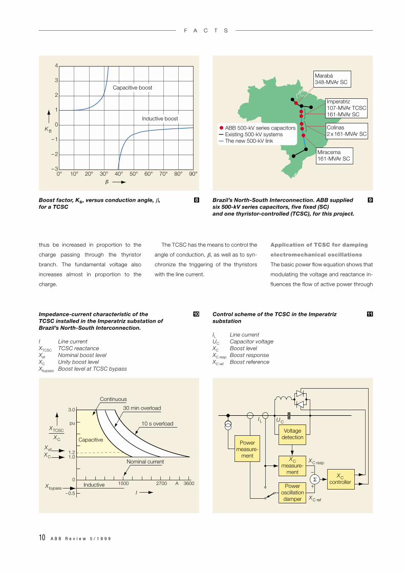
thus be increased in proportion to the
charge passing through the thyristor
branch. The fundamental voltage also
increases almost in proportion to the
charge.
The TCSC has the means to control the
angle of conduction, β, as well as to syn-
chronize the triggering of the thyristors
with the line current.
Application of TCSC for damping
electromechanical oscillations
The basic power flow equation shows that
modulating the voltage and reactance in-
fluences the flow of active power through
0° 20° 40° 60° 80°10° 30° 50° 70° 90°– 3
– 2
– 1
0
1
2
3
4
KB
β
Capacitive boost
Inductive boost
Marabá348-MVAr SC
Miracema161-MVAr SC
Colinas2 x 161-MVAr SC
Imperatriz107-MVAr TCSC161-MVAr SC
ABB 500-kV series capacitorsExisting 500-kV systemsThe new 500-kV link
XTCSC
XefXC
Xbypass
XC
Continuous
30 min overload
10 s overload
Nominal current
Inductive
Capacitive
3.0
pu
1.21.0
0
–0.5
1500 A 36002700
I
Powermeasure-
ment
IL UC
XC resp
XC ref
–
+
Voltagedetection
XCmeasure-
ment
Poweroscillationdamper
XCcontrollerΣ
Boost factor, KB , versus conduction angle, β, for a TCSC
8 Brazil’s North-South Interconnection. ABB supplied six 500-kV series capacitors, five fixed (SC) and one thyristor-controlled (TCSC), for this project.
9
Impedance-current characteristic of the TCSC installed in the Imperatriz substation of Brazil’s North-South Interconnection.
I Line currentXTCSC TCSC reactanceXef Nominal boost levelXC Unity boost levelXbypass Boost level at TCSC bypass
10 Control scheme of the TCSC in the Imperatriz substation
IL Line currentUC Capacitor voltageXC Boost levelXC resp Boost responseXC ref Boost reference
11
F A C T S
A B B R e v i e w 5 / 1 9 9 9 11
the transmission line. In principle, a TCSC
is capable of fast control of the active
power through a transmission line. The
possible control of transmittable power
points to this device being used to damp
electromechanical oscillations in the
power system. Features of this damping
effect are:
• The effectiveness of the TCSC for con-
trolling power swings increases with
higher levels of power transfer.
• The damping effect of a TCSC on an in-
tertie is unaffected by the location of
the TCSC.
• The damping effect is insensitive to the
load characteristic.
• When a TCSC is designed to damp
inter-area modes, it does not excite any
local modes.
Brazil:
North-South Interconnection
A current example of AC interconnection
of separate power systems within a coun-
try’s borders is found in Brazil. There are
two main power systems in the country
which were previously not interconnected
– the North System and the South Sys-
tem. They transmit mainly hydropower,
carrying more than 95 % of the nation’s
total generated electrical energy. After the
feasibility of interconnecting the two sys-
tems had been studied, it was decided to
build the transmission corridor. AC and
DC schemes were assessed before the
decision was taken in favour of the AC op-
tion. This consists of a single 500-kV com-
pact circuit (to be doubled at a later
stage), more than 1,000 km long and se-
ries-compensated at several locations
along the line. It has been in operation
since the beginning of 1999 .
The AC option is highly attractive as it
makes inexpensive hydropower available
to a rapidly growing federal economy and
for the future development of a vast area
9
with great economical potential. Several
hydropower plants are expected to be
built along this route and connected to the
500-kV AC grid in the next two decades.
ABB supplied a total of six 500-kV se-
ries capacitors for the project, five fixed
and one thyristor-controlled. In all, series
capacitors rated at about 1,100 MVAr
have been supplied.
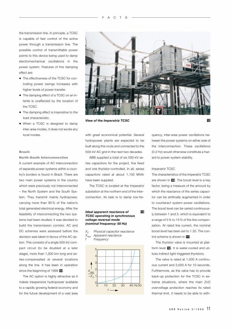
The TCSC is located at the Imperatriz
substation at the northern end of the inter-
connection. Its task is to damp low-fre-
quency, inter-area power oscillations be-
tween the power systems on either side of
the interconnection. These oscillations
(0.2 Hz) would otherwise constitute a haz-
ard to power system stability.
Imperatriz TCSC
The characteristics of the Imperatriz TCSC
are shown in . The boost level is a key
factor, being a measure of the amount by
which the reactance of the series capaci-
tor can be artificially augmented in order
to counteract system power oscillations.
The boost level can be varied continuous-
ly between 1 and 3, which is equivalent to
a range of 5 % to 15 % of the line compen-
sation. At rated line current, the nominal
boost level has been set to 1.20. The con-
trol scheme is shown in .
The thyristor valve is mounted at plat-
form level . It is water-cooled and uti-
lizes indirect light-triggered thyristors.
The valve is rated at 1,500 A continu-
ous current and 3,000 A for 10 seconds.
Furthermore, as the valve has to provide
back-up protection for the TCSC in ex-
treme situations, where the main ZnO
overvoltage protection reaches its rated
thermal limit, it needs to be able to with-
12
11
10
View of the Imperatriz TCSC 12
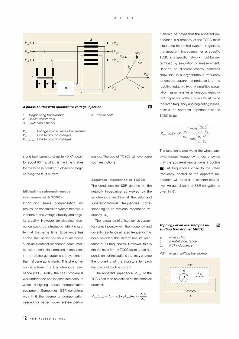
Ideal apparent reactance of TCSC operating in synchronousvoltage reversal mode (nominal frequency: 50 Hz)
XC Physical capacitor reactanceXapp Apparent reactance f Frequency
13
f
5
4
3
2
1
00 10 20 30 40 Hz50
Xapp
–XC
F A C T S
12 A B B R e v i e w 5 / 1 9 9 9
stand fault currents of up to 40 kA (peak)
for about 60 ms, which is the time it takes
for the bypass breaker to close and begin
carrying the fault current.
Mitigating subsynchronous
resonance with TCSCs
Introducing series compensation im-
proves the transmission system behaviour
in terms of the voltage stability and angu-
lar stability. However, an electrical reso-
nance could be introduced into the sys-
tem at the same time. Experience has
shown that under certain circumstances
such an electrical resonance could inter-
act with mechanical torsional resonances
in the turbine-generator shaft systems in
thermal generating plants. This phenome-
non is a form of subsynchronous reso-
nance (SSR). Today, the SSR problem is
well understood and is taken into account
when designing series compensation
equipment. Sometimes, SSR conditions
may limit the degree of compensation
needed for better power system perfor-
mance. The use of TCSCs will overcome
such restrictions.
Apparent impedance of TCSCs
The conditions for SSR depend on the
network impedance as viewed by the
synchronous machine at the sub- and
supersynchronous frequencies corre-
sponding to its torsional resonance fre-
quency, ωm.
The reactance of a fixed series capaci-
tor varies inversely with the frequency, and
once its reactance at rated frequency has
been selected this determines its reac-
tance at all frequencies. However, this is
not the case for the TCSC as its boost de-
pends on control actions that may change
the triggering of the thyristors for each
half-cycle of the line current.
The apparent impedance, Zapp, of the
TCSC can then be defined as the complex
quotient:
It should be noted that the apparent im-
pedance is a property of the TCSC main
circuit and its control system. In general,
the apparent impedance for a specific
TCSC in a specific network must be de-
termined by simulation or measurement.
Reports on different control schemes
show that in subsynchronous frequency
ranges the apparent impedance is of the
resistive-inductive type. A simplified calcu-
lation, assuming instantaneous, equidis-
tant capacitor voltage reversals at twice
the rated frequency and neglecting losses,
reveals the apparent impedance of the
TCSC to be:
The function is positive in the whole sub-
synchronous frequency range, showing
that the apparent reactance is inductive
. At frequencies close to the rated
frequency, control of the apparent im-
pedance will force it to become capaci-
tive. An actual case of SSR mitigation is
given in [6].
13
∆VaVai
Vai Vao
Vao
V bc
V biV ci
φ
Vbi Vbo
Vci Vco
3
1
2
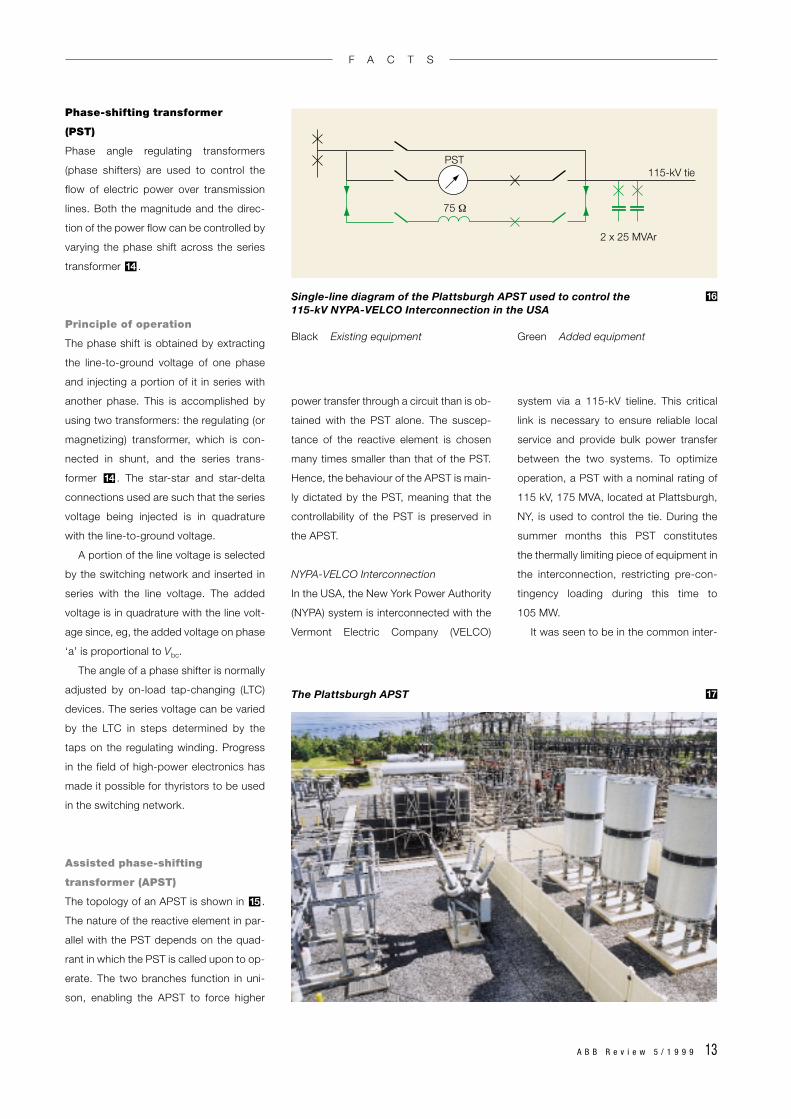
A phase shifter with quadrature voltage injection
1 Magnetizing transformer φ Phase shift2 Series transformer3 Switching network
Va Voltage across series transformerVai, bi, ci Line to ground voltagesVao, bo, co Line to ground voltages
14
PST
L
L lk+ –
φ
Topology of an assisted phase-shifting transformer (APST)
φ Phase shiftL Parallel inductanceLlk PST inductance
PST Phase-shifting transformer
15
Zapp (ωm ) = Rapp (ωm ) + jX app (ωm ) =
∆rUC
∆rIL
Xapp (ωm ) = – XC
ωn
ωm
1– cosωm
ωn
π
2
cosωm
ωn
π
2
F A C T S
A B B R e v i e w 5 / 1 9 9 9 13
Phase-shifting transformer
(PST)
Phase angle regulating transformers
(phase shifters) are used to control the
flow of electric power over transmission
lines. Both the magnitude and the direc-
tion of the power flow can be controlled by
varying the phase shift across the series
transformer .
Principle of operation
The phase shift is obtained by extracting
the line-to-ground voltage of one phase
and injecting a portion of it in series with
another phase. This is accomplished by
using two transformers: the regulating (or
magnetizing) transformer, which is con-
nected in shunt, and the series trans-
former . The star-star and star-delta
connections used are such that the series
voltage being injected is in quadrature
with the line-to-ground voltage.
A portion of the line voltage is selected
by the switching network and inserted in
series with the line voltage. The added
voltage is in quadrature with the line volt-
age since, eg, the added voltage on phase
‘a’ is proportional to Vbc.
The angle of a phase shifter is normally
adjusted by on-load tap-changing (LTC)
devices. The series voltage can be varied
by the LTC in steps determined by the
taps on the regulating winding. Progress
in the field of high-power electronics has
made it possible for thyristors to be used
in the switching network.
Assisted phase-shifting
transformer (APST)
The topology of an APST is shown in .
The nature of the reactive element in par-
allel with the PST depends on the quad-
rant in which the PST is called upon to op-
erate. The two branches function in uni-
son, enabling the APST to force higher
15
14
14
power transfer through a circuit than is ob-
tained with the PST alone. The suscep-
tance of the reactive element is chosen
many times smaller than that of the PST.
Hence, the behaviour of the APST is main-
ly dictated by the PST, meaning that the
controllability of the PST is preserved in
the APST.
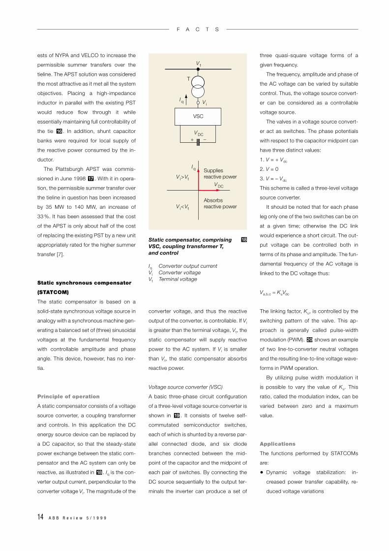
NYPA-VELCO Interconnection
In the USA, the New York Power Authority
(NYPA) system is interconnected with the
Vermont Electric Company (VELCO)
system via a 115-kV tieline. This critical
link is necessary to ensure reliable local
service and provide bulk power transfer
between the two systems. To optimize
operation, a PST with a nominal rating of
115 kV, 175 MVA, located at Plattsburgh,
NY, is used to control the tie. During the
summer months this PST constitutes
the thermally limiting piece of equipment in
the interconnection, restricting pre-con-
tingency loading during this time to
105 MW.
It was seen to be in the common inter-
PST115-kV tie
2 x 25 MVAr
75 Ω
Single-line diagram of the Plattsburgh APST used to control the 115-kV NYPA-VELCO Interconnection in the USA
Black Existing equipment Green Added equipment
16
The Plattsburgh APST 17
F A C T S
14 A B B R e v i e w 5 / 1 9 9 9
ests of NYPA and VELCO to increase the
permissible summer transfers over the
tieline. The APST solution was considered
the most attractive as it met all the system
objectives. Placing a high-impedance
inductor in parallel with the existing PST
would reduce flow through it while
essentially maintaining full controllability of
the tie . In addition, shunt capacitor
banks were required for local supply of
the reactive power consumed by the in-
ductor.
The Plattsburgh APST was commis-
sioned in June 1998 . With it in opera-
tion, the permissible summer transfer over
the tieline in question has been increased
by 35 MW to 140 MW, an increase of
33 %. It has been assessed that the cost
of the APST is only about half of the cost
of replacing the existing PST by a new unit
appropriately rated for the higher summer
transfer [7].
Static synchronous compensator
(STATCOM)
The static compensator is based on a
solid-state synchronous voltage source in
analogy with a synchronous machine gen-
erating a balanced set of (three) sinusoidal
voltages at the fundamental frequency
with controllable amplitude and phase
angle. This device, however, has no iner-
tia.
Principle of operation
A static compensator consists of a voltage
source converter, a coupling transformer
and controls. In this application the DC
energy source device can be replaced by
a DC capacitor, so that the steady-state
power exchange between the static com-
pensator and the AC system can only be
reactive, as illustrated in . Iq is the con-
verter output current, perpendicular to the
converter voltage Vi. The magnitude of the
18
17
16
converter voltage, and thus the reactive
output of the converter, is controllable. If Vi
is greater than the terminal voltage, Vt, the
static compensator will supply reactive
power to the AC system. If Vi is smaller
than Vt, the static compensator absorbs
reactive power.
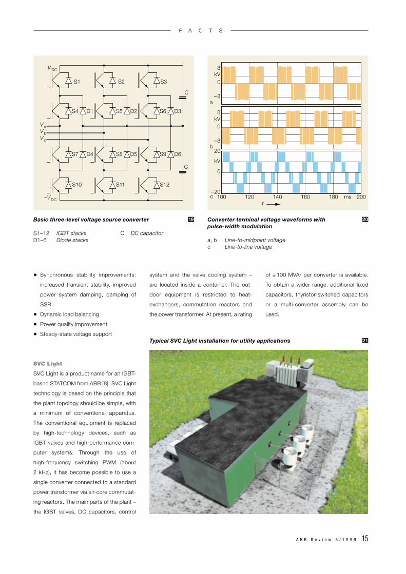
Voltage source converter (VSC)
A basic three-phase circuit configuration
of a three-level voltage source converter is
shown in . It consists of twelve self-
commutated semiconductor switches,
each of which is shunted by a reverse par-
allel connected diode, and six diode
branches connected between the mid-
point of the capacitor and the midpoint of
each pair of switches. By connecting the
DC source sequentially to the output ter-
minals the inverter can produce a set of
19
three quasi-square voltage forms of a
given frequency.
The frequency, amplitude and phase of
the AC voltage can be varied by suitable
control. Thus, the voltage source convert-
er can be considered as a controllable
voltage source.
The valves in a voltage source convert-
er act as switches. The phase potentials
with respect to the capacitor midpoint can
have three distinct values:
1. V = + Vdc
2. V = 0
3. V = – Vdc
This scheme is called a three-level voltage
source converter.
It should be noted that for each phase
leg only one of the two switches can be on
at a given time; otherwise the DC link
would experience a short circuit. The out-
put voltage can be controlled both in
terms of its phase and amplitude. The fun-
damental frequency of the AC voltage is
linked to the DC voltage thus:
Va,b,c = KuVdc
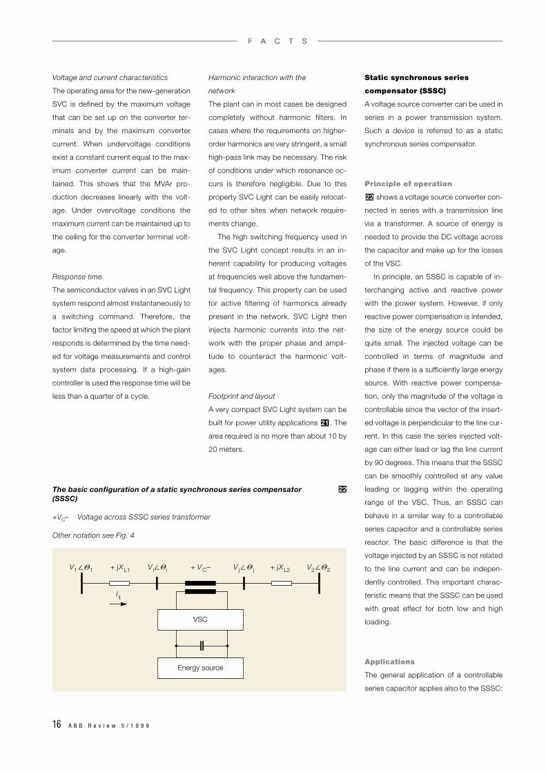
The linking factor, Ku, is controlled by the
switching pattern of the valve. This ap-
proach is generally called pulse-width
modulation (PWM). shows an example
of two line-to-converter neutral voltages
and the resulting line-to-line voltage wave-
forms in PWM operation.
By utilizing pulse width modulation it
is possible to vary the value of Ku. This
ratio, called the modulation index, can be
varied between zero and a maximum
value.
Applications
The functions performed by STATCOMs
are:
• Dynamic voltage stabilization: in-
creased power transfer capability, re-
duced voltage variations
20
V i
V i>Vt
V i<Vt
V t
VDC
VDC
Iq
Iq
T
Suppliesreactive power
Absorbsreactive power
–+
VSC
Static compensator, comprising VSC, coupling transformer T, and control
Iq Converter output currentVi Converter voltageVt Terminal voltage
18
F A C T S
A B B R e v i e w 5 / 1 9 9 9 15
• Synchronous stability improvements:
increased transient stability, improved
power system damping, damping of
SSR
• Dynamic load balancing
• Power quality improvement
• Steady-state voltage support
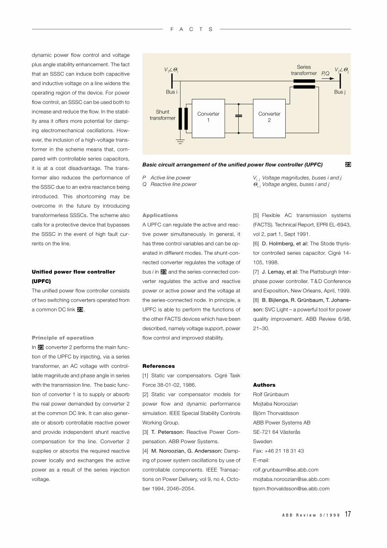
SVC Light
SVC Light is a product name for an IGBT-
based STATCOM from ABB [8]. SVC Light
technology is based on the principle that
the plant topology should be simple, with
a minimum of conventional apparatus.
The conventional equipment is replaced
by high-technology devices, such as
IGBT valves and high-performance com-
puter systems. Through the use of
high-frequency switching PWM (about
2 kHz), it has become possible to use a
single converter connected to a standard
power transformer via air-core commutat-
ing reactors. The main parts of the plant –
the IGBT valves, DC capacitors, control
system and the valve cooling system –
are located inside a container. The out-
door equipment is restricted to heat-
exchangers, commutation reactors and
the power transformer. At present, a rating
of ± 100 MVAr per converter is available.
To obtain a wider range, additional fixed
capacitors, thyristor-switched capacitors
or a multi-converter assembly can be
used.
+VDC
–VDC
Va
C
C
D6
D1 D2S4 S5 D3S6
D4 D5S7 S8 S9
S12S11S10
S1 S3S2
VbVc
8kV
kV
kV
0
–8
8
0
–8
20
0
–20100 120 140
t160 ms180 200
a
b
c
Basic three-level voltage source converter
S1–12 IGBT stacks C DC capacitorD1–6 Diode stacks
19 Converter terminal voltage waveforms with pulse-width modulation
a, b Line-to-midpoint voltagec Line-to-line voltage
20
Typical SVC Light installation for utility applications 21
F A C T S
16 A B B R e v i e w 5 / 1 9 9 9
Voltage and current characteristics
The operating area for the new-generation
SVC is defined by the maximum voltage
that can be set up on the converter ter-
minals and by the maximum converter
current. When undervoltage conditions
exist a constant current equal to the max-
imum converter current can be main-
tained. This shows that the MVAr pro-
duction decreases linearly with the volt-
age. Under overvoltage conditions the
maximum current can be maintained up to
the ceiling for the converter terminal volt-
age.
Response time
The semiconductor valves in an SVC Light
system respond almost instantaneously to
a switching command. Therefore, the
factor limiting the speed at which the plant
responds is determined by the time need-
ed for voltage measurements and control
system data processing. If a high-gain
controller is used the response time will be
less than a quarter of a cycle.
Harmonic interaction with the
network
The plant can in most cases be designed
completely without harmonic filters. In
cases where the requirements on higher-
order harmonics are very stringent, a small
high-pass link may be necessary. The risk
of conditions under which resonance oc-
curs is therefore negligible. Due to this
property SVC Light can be easily relocat-
ed to other sites when network require-
ments change.
The high switching frequency used in
the SVC Light concept results in an in-
herent capability for producing voltages
at frequencies well above the fundamen-
tal frequency. This property can be used
for active filtering of harmonics already
present in the network. SVC Light then
injects harmonic currents into the net-
work with the proper phase and ampli-
tude to counteract the harmonic volt-
ages.
Footprint and layout
A very compact SVC Light system can be
built for power utility applications . The
area required is no more than about 10 by
20 meters.
21
Static synchronous series
compensator (SSSC)
A voltage source converter can be used in
series in a power transmission system.
Such a device is referred to as a static
synchronous series compensator.
Principle of operation
shows a voltage source converter con-
nected in series with a transmission line
via a transformer. A source of energy is
needed to provide the DC voltage across
the capacitor and make up for the losses
of the VSC.
In principle, an SSSC is capable of in-
terchanging active and reactive power
with the power system. However, if only
reactive power compensation is intended,
the size of the energy source could be
quite small. The injected voltage can be
controlled in terms of magnitude and
phase if there is a sufficiently large energy
source. With reactive power compensa-
tion, only the magnitude of the voltage is
controllable since the vector of the insert-
ed voltage is perpendicular to the line cur-
rent. In this case the series injected volt-
age can either lead or lag the line current
by 90 degrees. This means that the SSSC
can be smoothly controlled at any value
leading or lagging within the operating
range of the VSC. Thus, an SSSC can
behave in a similar way to a controllable
series capacitor and a controllable series
reactor. The basic difference is that the
voltage injected by an SSSC is not related
to the line current and can be indepen-
dently controlled. This important charac-
teristic means that the SSSC can be used
with great effect for both low and high
loading.
Applications
The general application of a controllable
series capacitor applies also to the SSSC:
22
Energy source
I ij
VSC
V i∠ iV1∠ 1 V2∠ 2+ VC–+ jXL1 + jXL2V j∠ j ΘΘΘΘ
The basic configuration of a static synchronous series compensator (SSSC)
+VC– Voltage across SSSC series transformer
Other notation see Fig. 4
22
F A C T S
A B B R e v i e w 5 / 1 9 9 9 17
dynamic power flow control and voltage
plus angle stability enhancement. The fact
that an SSSC can induce both capacitive
and inductive voltage on a line widens the
operating region of the device. For power
flow control, an SSSC can be used both to
increase and reduce the flow. In the stabil-
ity area it offers more potential for damp-
ing electromechanical oscillations. How-
ever, the inclusion of a high-voltage trans-
former in the scheme means that, com-
pared with controllable series capacitors,
it is at a cost disadvantage. The trans-
former also reduces the performance of
the SSSC due to an extra reactance being
introduced. This shortcoming may be
overcome in the future by introducing
transformerless SSSCs. The scheme also
calls for a protective device that bypasses
the SSSC in the event of high fault cur-
rents on the line.
Unified power flow controller
(UPFC)
The unified power flow controller consists
of two switching converters operated from
a common DC link .
Principle of operation
In converter 2 performs the main func-
tion of the UPFC by injecting, via a series
transformer, an AC voltage with control-
lable magnitude and phase angle in series
with the transmission line. The basic func-
tion of converter 1 is to supply or absorb
the real power demanded by converter 2
at the common DC link. It can also gener-
ate or absorb controllable reactive power
and provide independent shunt reactive
compensation for the line. Converter 2
supplies or absorbs the required reactive
power locally and exchanges the active
power as a result of the series injection
voltage.
23
23
Applications
A UPFC can regulate the active and reac-
tive power simultaneously. In general, it
has three control variables and can be op-
erated in different modes. The shunt-con-
nected converter regulates the voltage of
bus i in and the series-connected con-
verter regulates the active and reactive
power or active power and the voltage at
the series-connected node. In principle, a
UPFC is able to perform the functions of
the other FACTS devices which have been
described, namely voltage support, power
flow control and improved stability.
References
[1] Static var compensators. Cigré Task
Force 38-01-02, 1986.
[2] Static var compensator models for
power flow and dynamic performance
simulation. IEEE Special Stability Controls
Working Group.
[3] T. Petersson: Reactive Power Com-
pensation. ABB Power Systems.
[4] M. Noroozian, G. Andersson: Damp-
ing of power system oscillations by use of
controllable components. IEEE Transac-
tions on Power Delivery, vol 9, no 4, Octo-
ber 1994, 2046–2054.
23
[5] Flexible AC transmission systems
(FACTS). Technical Report, EPRI EL-6943,
vol 2, part 1, Sept 1991.
[6] D. Holmberg, et al: The Stode thyris-
tor controlled series capacitor. Cigré 14-
105, 1998.
[7] J. Lemay, et al: The Plattsburgh Inter-
phase power controller. T & D Conference
and Exposition, New Orleans, April, 1999.
[8] B. Bijlenga, R. Grünbaum, T. Johans-
son: SVC Light – a powerful tool for power
quality improvement. ABB Review 6/98,
21–30.
Authors
Rolf Grünbaum
Mojtaba Noroozian
Björn Thorvaldsson
ABB Power Systems AB
SE-721 64 Västerås
Sweden
Fax: +46 21 18 31 43
E-mail:
P,Q
Bus i Bus j
Converter1
Converter2
Seriestransformer
Shunttransformer
V j∠ jΘV i∠ iΘ
Basic circuit arrangement of the unified power flow controller (UPFC)
P Active line power Vi, j Voltage magnitudes, buses i and jQ Reactive line power Θi, j Voltage angles, buses i and j
23
F A C T S