
Factory Gateway User Manual - Schneider · PDF fileFactory Gateway's power cord is not...
41
User Manual
Transcript of Factory Gateway User Manual - Schneider · PDF fileFactory Gateway's power cord is not...

User Manual

Factory Gateway Series User Manual 1
1. It is forbidden to copy the contents of this manual, in whole or in part, except forthe user’s personal use, without the express permission of Digital ElectronicsCorporation of Japan.
2. The information provided in this manual is subject to change without notice.
3. This manual has been written with care and attention to detail; however, shouldyou find any errors or omissions, contact Digital Electronics Corporation andinform them of your findings.
4. Please be aware that Digital Electronics Corporation shall not be held liable by theuser for any damages, losses, or third party claims arising from any uses of thisproduct.
All Company/Manufacturer names used in this manual are the registered trademarks ofthose companies.
© Copyright 2002 Digital Electronics Corporation
PrefaceThank you for purchasing the Pro-face Graphic Logic Controller Factory GatewaySeries (hereby referred to as “Factory Gateway” or “Factory Gateway unit”).
This unit is designed to be connected to an External Device (PLC, etc.) that do not havetheir own Ethernet interface, via the Pro-Server system’s Ethernet connection. Pro-Server allows the Factory Gateway unit to communicate with a host-level PC withoutspecialized programming. This allows data collection and sharing of data with other PLCunits.
Also, Pro-Server’s Add-on software, GP-Viewer and GP-Web, allow you to accessfactory floor data from a remote PC, and even perform maintenance.
In this manual’s examples, the Mitsubishi MELSEC-AnA Series PLC is used wheneverpossible, connected in a one-to-one relationship with a Factory Gateway
< Note >

Preface
Factory Gateway Series User Manual2
Table of ContentsPreface ........................................................................................................................ 1
Essential Safety Precautions ................................................................................... 4
General Safety Precautions ..................................................................................... 7
About Factory Gateway Models ............................................................................ 8
Package Contents ..................................................................................................... 8
UL/c-UL (CSA) Application Notes .......................................................................... 9
CE Marking Notes .................................................................................................. 9
Documentation Conventions .................................................................................. 10
CHAPTER 1 INTRODUCTION
1.1 Prior to Operating the Factory Gateway.................................................... 1-1
1.2 System Design............................................................................................... 1-3
1.3 Accessories .................................................................................................... 1-4
CHAPTER 2 SPECIFICATIONS
2.1 General Specifications ................................................................................. 2-1
2.1.1 Electrical ..............................................................................................2-1
2.1.2 Environmental ......................................................................................2-2
2.1.3 Structural .............................................................................................2-3
2.2 Functional Specifications ............................................................................. 2-3
2.2.1 Clock ...................................................................................................2-3
2.2.2 Interfaces .............................................................................................2-3
2.3 Interface Specifications................................................................................ 2-5
2.3.1 Serial Interface ....................................................................................2-5
2.4 Part Names and Functions ........................................................................... 2-6
2.5 Dimensions .................................................................................................... 2-8
CHAPTER 3 INSTALLATION AND WIRING
3.1 Installation ..................................................................................................... 3-1
3.2 Wiring Cautions............................................................................................. 3-2
3.2.1 Connecting the Power Cord ................................................................3-2
3.2.2 Connecting the Power Supply .............................................................3-4
3.2.3 Grounding ............................................................................................3-5
3.2.4 I/O Signal Line Cautions......................................................................3-6
3.3 Tool Connector .............................................................................................. 3-6
3.4 Ethernet Cable Connector ........................................................................... 3-7

Factory Gateway Series User Manual 3
Preface
3.5 IP Address Settings ...................................................................................... 3-7
3.6 Dip Switch Settings ....................................................................................... 3-8
3.6.1 Initializing Memory ..............................................................................3-9
CHAPTER 4 TROUBLESHOOTING
4.1 Troubleshooting ............................................................................................. 4-1
4.1.1 LED Status Indicators .........................................................................4-2
4.1.2 Problem Solving...................................................................................4-4
4.2 Periodic Check Points................................................................................... 4-5

Preface
Factory Gateway Series User Manual4
WARNING
CAUTION
WARNINGS
Essential Safety PrecautionsThis manual includes procedures that must be followed to operate the FACTORYGATEWAY correctly and safely. Be sure to read this manual and any related materialsthoroughly to understand the correct operation and functions of the FACTORY GATE-WAY unit.
Safety SymbolsPlease pay attention to the following safety symbols and their meanings:
Indicates situations that may result in majormachine damage, severe bodily injury, or deathif the instructions are not followed.
Indicates situations that may result in damageto the machinery, or minor bodily injury if theinstructions are not followed.
System Design
• Please design your system so that equipment will not mal-function due to a communication fault between the Fac-tory Gateway and its host controller This is to preventany possibility of bodily injury or material damage.
• Do not use the Factory Gateway unit as a warning devicefor critical alarms that can cause serious operator injury,machine damage or production stoppage. Critical alarmindicators and their control/activator units must be de-signed using stand-alone hardware and/or mechanicalinterlocks.
• The Factory Gateway is not appropriate for use with air-craft control devices, aerospace equipment, central trunkdata transmission (communication) devices, nuclearpower control devices, or medical life support equipment,due to these devices’ inherent requirements of extremelyhigh levels of safety and reliability.

Factory Gateway Series User Manual 5
Preface
WARNINGS
• When using the Factory Gateway with transportation ve-hicles (trains, cars and ships), disaster and crime pre-vention devices, various types of safety equipment, nonlife-support related medical devices, etc. redundant and/or fail-safe system designs should be used to ensure theproper degree of reliability and safety.
Installation• High voltage runs through the Factory Gateway. Never
disassemble the Factory Gateway, otherwise an electricshock can occur.
• Do not modify the Factory Gateway unit. Doing so maycause a fire or an electric shock.
• Do not use the Factory Gateway in an environment whereflammable gasses are present, since operating the Fac-tory Gateway may cause an explosion.
Wiring• To prevent an electric shock, be sure to confirm that the
Factory Gateway's power cord is not connected to themain power when connecting any cords, cables or linesto the Factory Gateway.
• Be sure to replace the Factory Gateway’s plastic terminalblock cover after wiring is completed, since operating theFactory Gateway without the cover may lead to an elec-tric shock.
• Do not use power beyond the Factory Gateway's speci-fied voltage range. Doing so may cause a fire or an elec-tric shock.
Maintenance
• The Factory Gateway uses a lithium battery for backingup its internal clock data. If the battery is incorrectly re-placed, the battery may explode. To prevent this, pleasedo not replace the battery yourself. When the batteryneeds to be replaced, please contact your local FactoryGateway distributor.

Preface
Factory Gateway Series User Manual6
CAUTIONS
Installation
• Be sure to securely connect all cable connectors to theFactory Gateway. A loose connection may cause incor-rect input or output.
Wiring• Ground the Factory Gateway's FG line separately from
other units’ FG lines. Putting these FG lines too closemay cause an electric shock or unit malfunction. Be sureto use a grounding resistance of 100ΩΩΩΩΩ or less and a 2mm2
or thicker wire, or your country’s applicable standard.
• When wiring the Factory Gateway, be sure that the ratedvoltage and terminal layout are within the designatedrange. If the voltage supplied differs from the rated volt-age, or incorrect wiring or grounding is performed, it maycause a fire or unit malfunction.
• Use only the designated torque to tighten the FactoryGateway's terminal block screws. If these screws are nottightened firmly, it may cause a short-circuit, fire, or Fac-tory Gateway malfunction.
• Be careful that metal filings and wiring debris do not fallinside the Factory Gateway, since they can cause a fire,Factory Gateway malfunction, or incorrect operation.
Unit Disposal
• When this unit is disposed of, it should be done so ac-cording to your country's regulations for similar types ofindustrial waste.

Factory Gateway Series User Manual 7
Preface
• Do not install the Factory Gateway where the ambient tem-perature can exceed the allowed range. Doing so maycause the Factory Gateway to malfunction or shorten itsoperation life.
• Do not restrict or limit the Factory Gateway’s naturallyoccurring rear-face ventilation, or store or use the Fac-tory Gateway in an environment that is too hot.
• Do not use this unit in areas where large, sudden tem-perature changes can occur. These changes can causecondensation to form inside the unit, possibly causingthe unit to malfunction.
• Do not allow water, liquids, metal or charged particles toenter inside the Factory Gateway’s case, since they cancause either a Factory Gateway malfunction or an elec-trical shock.
• Do not use or store the Factory Gateway in direct sun-light, or in excessively dusty or dirty environments.
• Do not store or use the unit where strong jolting or ex-cessive vibration can occur.
• Do not store or use the Factory Gateway where chemi-cals (such as organic solvents, etc.) and acids can evapo-rate, or where chemicals and acids are present in the air.Corrosive chemicals: Acids, alkalies, liquids containing salt
Flammable chemicals:Organic Solvents• Do not use paint thinner or organic solvents to clean the
Factory Gateway.
General Safety Precautions

Preface
Factory Gateway Series User Manual8
Package Contents
About Factory Gateway ModelsThe Factory Gateway Series in this manual refers to the following Factory Gatewaymodel numbers:
The following items are included in the Factory Gateway's package. Before using theFactory Gateway, please confirm that all items listed here are present.
Factory Gateway Unit (1)
(FGW-SE41-24V)
InstallationGuide
This unit has been carefully packed, with special attention to quality. However, shouldyou find anything damaged or missing, please contact your local Factory Gatewaydistributor immediately.
Installation Guide (1)
Series NameModel
NumberComments
GP Type withScreen Creation
Software
Factory Gateway FGW-SE41-24VUL/c-UL Approved
CE Marked
Factory Gateway
FGW-SE
Factory Gateway Series User Manual 9
Preface
UL/c-UL (CSA) Application Notes
CE Marking Notes
The FGW-SE41-24V is a UL/c-UL (CSA) recognized unit. (UL FileNo. E220851)
The FGW-SE41-24V unit conforms to the following standards.UL508 Electrical Control System for IndustryCAN/CSA-C22.2 No.1010-1(Safety requirements for electrical equipment for measurement andlaboratory use)FGW-SE41-24V (UL Registration Model: 3080034-01)
<Notes>The Factory Gateway must be installed in other equipment.If the unit is installed in an area with no air conditioning system, besure to attach the DIN rail to the rear of the unit. Also, be sure theunit is installed so it is at least 100 mm away from all of the unit’sdirections except the rear side. If these requirements are not met, theheat generated by the unit’s internal components may cause the unitto fail to meet UL standards requirements.The power supply unit connected to the I/O unit must be a UL/c-UL(CSA) approved Class 2 power supply unit or Class 2 trans-former*1. When the Factory Gateway or multiple I/O units underload are operated with a single power supply, the amount of currentconsumption and full-load current of the I/O units must be within therated load of the Class 2 power supply unit or Class 2 power supplytransformer. Be aware that the number of points which can beturned ON simultaneously may be limited, depending on the amountof load and load current value.
The FGW-SE41-24V is a CE Marked unit that conforms to EMC directives EN55011Class A and EN61000-6-2.
<Caution>
While this unit is officially marked as conforming to the relevant EMC directives, it is theuser’s final application of this unit in a larger system (i.e. the machinery, wiring, controlpanel, installation method, etc.) that will determine if this unit maintains or loses thisconformance marking. Therefore, it is strongly advised that the user investigate andconfirm whether their overall system (i.e. all related machinery and equipment) alsoconforms with these EMC directives.
*1 A Class 2 power supply unit or Class 2 power supply transformer is defined byNEC as being 30V and, at 8A or less output, less than 100VA.
Preface
Factory Gateway Series User Manual10
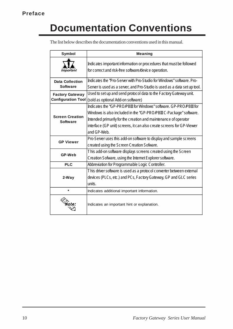
Documentation ConventionsThe list below describes the documentation conventions used in this manual.
Symbol Meaning
Indicates important information or procedures that must be followed
for correct and risk-free software/device operation.
Data CollectionSoftware
Indicates the "Pro-Server with Pro-Studio for Windows" software. Pro-
Server is used as a server, and Pro-Studio is used as a data set up tool.
Factory GatewayConfiguration Tool
Used to set up and send protocol data to the Factory Gateway unit.
(sold as optional Add-on software)
Indicates the "GP-PRO/PBIII for Windows" software. GP-PRO/PBIII for
Windows is also included in the "GP-PRO/PBIII C-Package" software.
Intended primarily for the creation and maintenance of operator
interface (GP unit) screens, it can also create screens for GP-Viewer
and GP-Web.
GP ViewerPro-Server uses this add-on software to display and sample screens
created using the Screen Creation Sofware.
GP-WebThis add-on software displays screens created using the Screen
Creation Sofware, using the Internet Explorer software.
PLC Abbreviation for Programmable Logic Controller.
2-Way
This driver software is used as a protocol converter between external
devices (PLCs, etc.) and PCs, Factory Gateway, GP and GLC series
units.
* Indicates additional important information.
Indicates an important hint or explanation.
Screen CreationSoftware

Factory Gateway Series User Manual 1–1
1.1 Prior to Operating the Factory Gateway
Use the following steps to create projects for the Factory Gateway unit.
Chapter1 Introduction
1. Prior to Operating theFactory Gateway
2. System Design
3. Accessories
Factory Gateway Setup and WiringSetupWiringIP Address Setup
Software InstallationPro-Server with Pro-Studio for WindowsFactory Gateway Configuration Tool
Create Network Project FileSearch for Factory GatewaRegister Factory Gateway as a nodeEnter Factory Gateway Network SettingsSet up wiringSend Network Project File
Factory Gateway Serial Data TransferStart up Factory Gateway Configuration ToolsSearch for Factory GatewaySet up Serial Data Transfer SettingsSelect and set up protocolSend protocol and setting data
When using GP-Web or GP-Viewer, screen creation softwaremust first be installed, screens created and data sent to theFactory Gateway unit.
Factory Gateway Configuration Tool Opera-tion Manual
This manual explains the hardware settings used to set up the FActory Gateway unit.For detailed information about operation of the Factory Gateway Configuration Tool, orPro-Server with Pro-Studio for Windows, please refer to the following manuals
Factory Gateway Configuration Tool Operation Manual
Pro-Server with Pro-Studio for Windows Operation Manual
Pro-Server with Pro-Studio for Windows Operation Manual
Factory Gateway Con-figuration Tool Operation Manual
Chapter 3 Setup andWiring GP-PRO/PBIII Device/PLCConnection Manual
Pro-Server with Pro-Studio for Windows OperationManual
Factory GatewayConfiguration Tool OperationManual

Chapter 1 – Introduction
Factory Gateway Series User Manual1–2
Factory Gateway Unit
RUN Mode
1.2 System DesignThe following diagram represents the main selection of devices connectable to theFactory Gateway unit.
Factory Gateway RUN ModePeripherals
RS-232C CableGP410-IS00-O*4
RS-422 CableGP230-IS11-O*4
GP230-IS12-O*4
(for Multi-link cable)
RS-422 ConnectorTerminal AdapterGP070-CN10-O*4
Mitsubishi PLC FX-SeriesProgram Port I/F CableGP430-IP11-O
Mitsubishi PLC A-SeriesProgram Port I/F CableGP430-IP10-O
Mitsubishi PLCA, Q, C, FX Series2-PortAdapter IIGP070-MD11
HostController
(PLCs, etc.)2-Port AdapterII CableGP070-MDCB11
(6)
PersonalComputer
Data Transfer CableGPW-CB02
Edit Mode
Internet/
Intranet
ClientPC Host PC - Pro-Server- Pro-Studio- GP-Viewer*2
- GP-Web Server*1
- IIS*1
GP-WEBClient *1
Ethernet
(1)(2)
Mitsubishi GPPSoftware*3
(6)
(6)
(5)
(4) (3)

Factory Gateway Series User Manual 1–3
Chapter 1 – Introduction
1. Required when using GP-Web.
2. Required when using GP-Viewer
3. For information about compatible PLC types and software, referto the GP-PRO/PB III for Windows Device/PLC ConnectionManual (included in the GP-PRO/PB III software).
4. Certain PLC types and models cannot be connected.
Refer to the GP-PRO/PB III for Windows Device/PLC Connec-tion Manual (included in the GP-PRO/PB III software).
5. For the full range of compatible PCs, refer to the following manual.
Refer to the GP-PRO/PB III for Windows Operation Manual(included in the GP-PRO/PB III software).
6. Normally, maintenance (data transfer) is possible using an Ethernet network.However, depending on the data transfer cable used, a Factory Gateway SystemError may occur, preventing communication.
- Pro-Server
- Pro-Studio
- Factory Gateway Configuration Tool
- GP-PRO/PBIII for Windows*1, *2
- GP-Viewer*2
- GP-Web Screen Compiler*1
GP-PRO/PBIII forWindows
*6Factory Gateway Unit
(1)(2)
Personal Computer
Data Transfer CableGPW-CB02
Factory GatewayInterfaces(1) Ethernet
(2) Tool Connector
(3) Serial Interface
PLC Interfaces
(4) RS-232C Port
(5) RS-422 Port
(6) ProgrammingConsole Port
Chapter 1 – Introduction
Factory Gateway Series User Manual1–4
Tool Connector
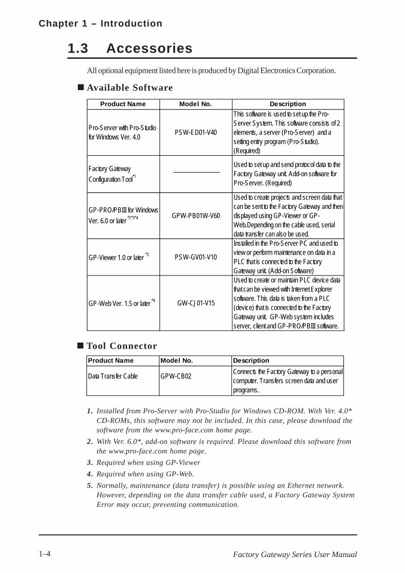
1.3 Accessories
All optional equipment listed here is produced by Digital Electronics Corporation.
Available Software
Product Name Model No. Description
Data Transfer Cable GPW-CB02Connects the Factory Gateway to a personalcomputer. Transfers screen data and userprograms.
Product Name Model No. Description
Pro-Server with Pro-Studiofor Windows Ver. 4.0
PSW-ED01-V40
This software is used to set up the Pro-Server System. This software consists of 2elements, a server (Pro-Server) and asetting entry program (Pro-Studio).(Required)
Factory Gateway
Configuration Tool*1
Used to set up and send protocol data to theFactory Gateway unit. Add-on software forPro-Server. (Required)
GP-PRO/PBIII for Windows
Ver. 6.0 or later *2*3*4 GPW-PB01W-V60
Used to create projects and screen data thatcan be sent to the Factory Gateway and thendisplayed using GP-Viewer or GP-Web.Depending on the cable used, serialdata transfer can also be used.
GP-Viewer 1.0 or later *3 PSW-GV01-V10
Installed in the Pro-Server PC and used toview or perform maintenance on data in aPLC that is connected to the FactoryGateway unit. (Add-on Software)
GP-Web Ver. 1.5 or later *4 GW-CJ01-V15
Used to create or maintain PLC device datathat can be viewed with Internet Explorersoftware. This data is taken from a PLC(device) that is connected to the FactoryGateway unit. GP-Web system includesserver, client and GP-PRO/PBIII software.
1. Installed from Pro-Server with Pro-Studio for Windows CD-ROM. With Ver. 4.0*CD-ROMs, this software may not be included. In this case, please download thesoftware from the www.pro-face.com home page.
2. With Ver. 6.0*, add-on software is required. Please download this software fromthe www.pro-face.com home page.
3. Required when using GP-Viewer
4. Required when using GP-Web.
5. Normally, maintenance (data transfer) is possible using an Ethernet network.However, depending on the data transfer cable used, a Factory Gateway SystemError may occur, preventing communication.

Factory Gateway Series User Manual 1–5
Chapter 1 – Introduction
1. For details about the range of connectable PLCs:
Refer to the GP-PRO/PB III for Windows Device/PLC Connec-tion Manual (included with the GP-PRO/PB III software).
Serial InterfacesProduct Name Model No. Description
RS-232C Cable*1 GP410-IS00-O
RS-422 Cable*1 GP230-IS11-ORS-422 Terminal Block
Adapter*1 GP070-CN10-OConversion adapter to convert serial data toRS-422 format.
2 Port Adapter II GP070-MD11Interface unit that allows use of both Factorygateway and Mitsubishi A, Q, C and FX seriesequipment in the same location.
2 Port Adapter II Cable GP070-MDCB11Connects the Factory Gateway to the 2-PortAdapter II.
M itsubishi A SeriesProgramming Port I/F Cable
GP430-IP10-O
Mitsubishi FX SeriesProgramming Port I/F Cable
GP430-IP11-O
Interface cables between the host (PLC) and theFactory Gateway.
Connects directly to M itsubishi's PLC I/FProgramming Console. Simultaneous use ofprogram console, however, is not possible.
Maintenance ItemsProduct Name Model No. Description
Connector CoverPS-BH00 Side face connector cover.

Chapter 1 – Introduction
Factory Gateway Series User Manual1–6
Memo

Factory Gateway Series User Manual 2–1
2.1 General Specifications
2.1.1 Electrical
Chapter2 Specifications
1. General Specifications2. Functional Specifications3. Interface Specifications4. Part Names and Functions5. Dimensions
Rated VoltageRated Voltage RangeAllowable Voltage DropPower ConsumptionIn-Rush CurrentVoltage EnduranceInsulation Resistance
DC 24VDC 19.2V to DC 28.8V
10MΩ or more at DC 500V (between charging and FG terminals)
10ms max.10W max.30A max.AC 500V 20mA for 1 minute (between charging and FG terminals)

Chapter 2 – Specifications
Factory Gateway Series User Manual2–2
2.1.3 Structural
2.1.2 Environmental
Ambient OperatingTemperatureStorage Temperature
Ambient Humidity
Storage Humidity
Air Purity (Dust)AtmosphereAtmosheric Endurance(GLC OperationAltitude)
Shock Resistance
Noise Immunity(via noise simulator)
Electrostatic DischargeImmunity
Vibration Resistance
0oC to +55oC
-20oC to +60oC10%RH to 90%RH
(non-condensing, wet bulb temperature: 39oC max.)10%RH to 90%RH
(non-condensing, wet bulb temperature: 39oC max.)0.1mg/m3 max. (non-conductive levels)Free of corrosive gasses
800hPa to 1,114hPa (2000 meters max.)
IEC61131-2 (JIS B 3501) compliant
(147m/s2, three times for each [X, Y, Z] direction)
IEC61131-2 (JIS B 3501) compliant
(10 times [80 min.] for each [X, Y, Z] direction)Noise Voltage: 1200Vp-p, Pulse Duration: 1µsRise Time: 1nsContact Discharge Method 6kV(complies with IEC 61000-4-2 Level 3)
When Vibration is NOT Continuous10Hz to 57Hz 0.075mm, 57Hz to 150Hz 9.8m/s2
When Vibration is Continuous10Hz to 57Hz 0.035mm, 57Hz to 150Hz 4.9m/s2
GroundingExternal DimensionsWeightCooling Method
Approx. 0.6 kg [1.32 lb]Natural air circulation
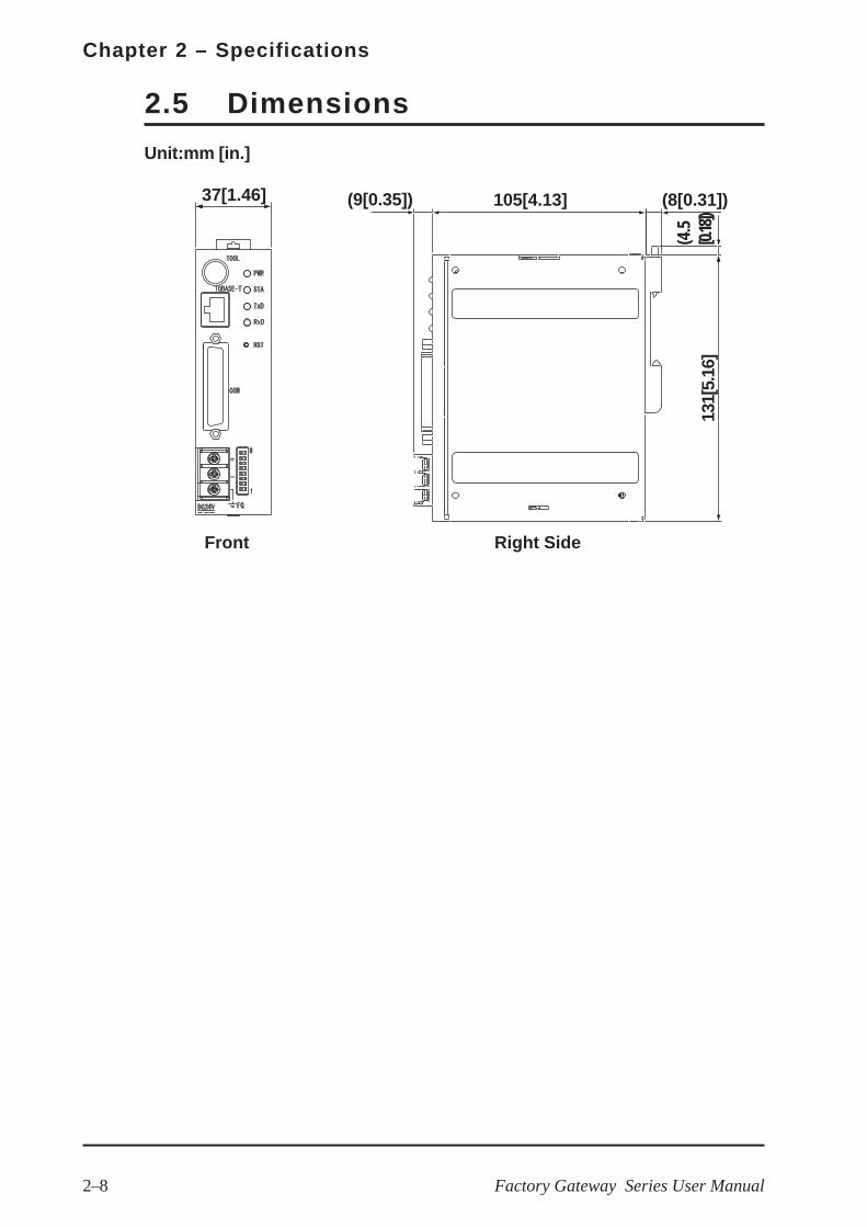
100Ω max., or your country's applicable standardW37mm x H131mm x D105mm [1.46 in.x 5.16 in. x 4.13 in.]
Factory Gateway Series User Manual 2–3
Chapter 2 – Specifications
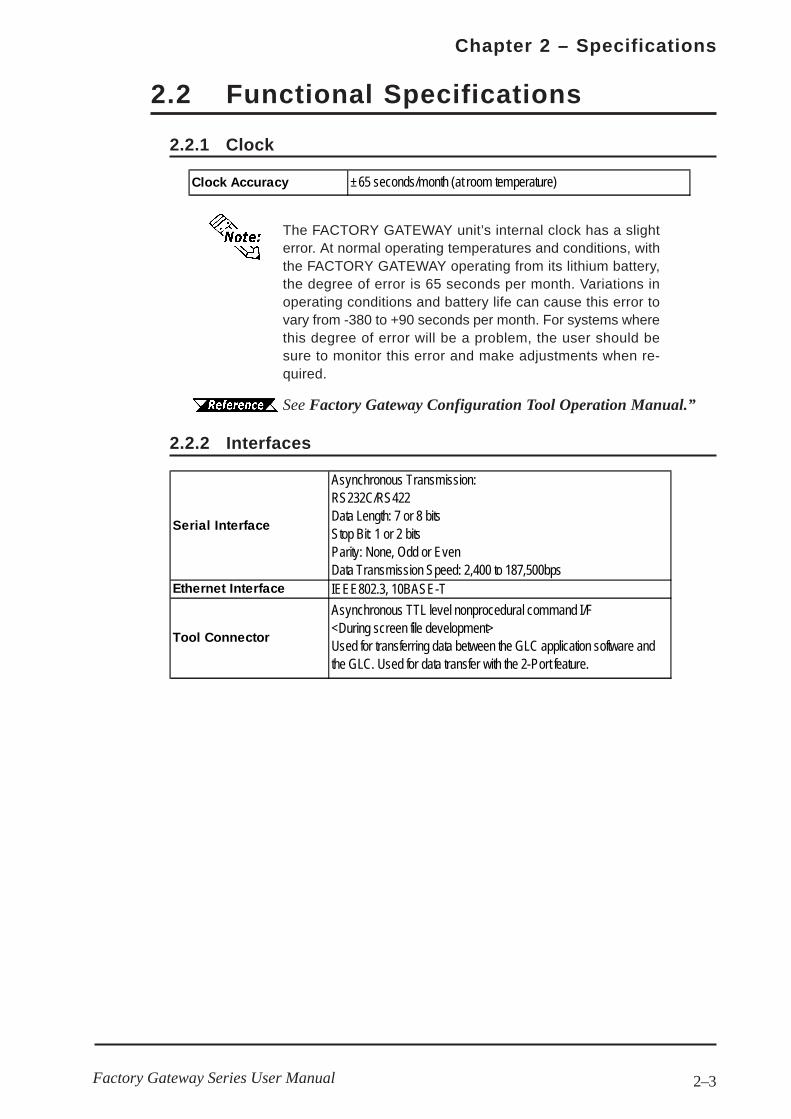
Clock Accuracy ±65 seconds/month (at room temperature)
2.2 Functional Specifications
The FACTORY GATEWAY unit’s internal clock has a slighterror. At normal operating temperatures and conditions, withthe FACTORY GATEWAY operating from its lithium battery,the degree of error is 65 seconds per month. Variations inoperating conditions and battery life can cause this error tovary from -380 to +90 seconds per month. For systems wherethis degree of error will be a problem, the user should besure to monitor this error and make adjustments when re-quired.
See Factory Gateway Configuration Tool Operation Manual.”
2.2.1 Clock
2.2.2 Interfaces
Serial Interface
Ethernet Interface
Tool Connector
Asynchronous Transmission:RS232C/RS422Data Length: 7 or 8 bitsStop Bit: 1 or 2 bitsParity: None, Odd or EvenData Transmission Speed: 2,400 to 187,500bpsIEEE802.3, 10BASE-T
Asynchronous TTL level nonprocedural command I/F<During screen file development>Used for transferring data between the GLC application software andthe GLC. Used for data transfer with the 2-Port feature.

Chapter 2 – Specifications
Factory Gateway Series User Manual2–4
Pin Assignments Pin # Signal Name Condition1 FG Frame ground2 SD Send data (RS-232C)3 RD Receive data (RS-232C)
SIO 4 RS Request send (RS-232C)5 CS Clear send (RS-232C)6 DR Data Set Ready (RS-232C)7 SG Signal ground8 CD Carrier detect (RS-232C)9 TRMX Termination (RS-422)10 RDA Receive data A (RS-422)11 SDA Send data A (RS-422)12 NC No connection (Reserved)13 NC No connection (Reserved)14 VCC 5V±5% output 0.25A15 SDB Send data B (RS-422)16 RDB Receive data B (RS-422)17 RI Ring Indicate (RS-232C)18 CSB Clear send B (RS-422)19 ERB Enable receive B (RS-422)20 ER Enable receive (RS-232C)21 CSA Clear send A (RS-422)22 ERA Enable receive A (RS-422)23 NC No connection (Reserved)24 NC No connection (Reserved)25 NC No connection (Reserved)
1
13
25
14
2.3 Interface Specifications
2.3.1 Serial Interface
This interface can be either RS-232C or RS-422. Connects FACTORY GATEWAY toHost (PLC). This interface uses a socket-type connector.
Recommended Parts
Connector Dsub25pin plug XM2A-2501 (OMRON)
Cover Dsub25pin cover XM2S-2511 (OMRON)
Dsub25pin cover XM2S-2521 (OMRON)
Jack Screws XM2Z-0071 (OMRON)
Cable CO-MA-VV-SB5PX 28AWG (Hitachi Cable Ltd.)
Use rough metric type M2.6x0.45 p threads used to securethe cable’s set screws.
To confirm your PLC unit’s connection specifications, refer to theGP-PRO/PB III for Windows Device/PLC Connection Manual (in-cluded in the GP-PRO/PB III C-Package01).

Factory Gateway Series User Manual 2–5
Chapter 2 – Specifications
Use the following instructions to create your own cable:
With an RS-422 cable:
• The following pins must be shorted as follows:
#18 (CSB) and #19 (ERB)
#21 (CSA) and #22 (ERA)
• Connecting the RS-422 cable’s #9 (TRMX) and #10 (RDA)pins inserts a termination resistance of 100Ω between#10 (RDA) and #16 (RDB).
• When making a cable for a Memory Link system, use a4-wire type cable.
With an RS-232C cable:
• Do NOT use the following pins:
#9 (TRMX), #10 (RDA), #11 (SDA), #15 (SDB), #16 (RDB),#18 (CSB), #19 (ERB), #21 (CSA), #22 (ERA)
• Connect the #1 (FG) terminal only if it is required by aconnected device.
• This FACTORY GATEWAY unit’s serial port is not isolated. When thehost (PLC) unit is also not isolated, and to reduce the risk of damag-ing the RS-422 circuit, be sure to connect the #7 SG (Signal Ground)terminal.
• Pin #14 (VCC) DC 5V Output is not protected. To prevent damage orunit malfunction, use only the designated level of current.

Chapter 2 – Specifications
Factory Gateway Series User Manual2–6
E
FG
H
I
A
B
C
D J
K
A : Tool Connector
Connects the data transfer cable when transferringdata for maintenance or when using 2-Port feature.
B : Ethernet I/F(10BASE-T)
Provides a 10BASE-T interface.
C : Network Status LED
These LEDs are positioned vertically and indicatethe Ethernet data transfer status.
D : Serial I/F(Dsub 25pin)
Used for the Dsub25 pin’s RS-232C and RS-422cables. Is connected to the Host (PLC.)
2.3 Interface Specifications
E : Power Input Terminal Block
Connects the power cord.
F : Power LED (PWR)
This LED indicates the Factory Gateway’s status.
G : Error Status LED (STA)
For details, see 4.1.1 LED StatusIndicators
Location Color Indicates Not Lit Indicates
Upper GreenReady to
transfer data
Not connected to
network / Network
trouble
Lower YellowTransferring
dataNot transferring data
LED Factory Gateway StatusGreen Normal operationRed Data transfer (OFFLINE) mode
Orange Initializing internal memory
Not Lit System program error
2.4 Part Names and Functions
Front
LED Factory Gateway StatusGreen Normal operationRed System error / Screen memory data is damaged
Orange 2-Way feature error
Not Lit System Program Error

Factory Gateway Series User Manual 2–7
Chapter 2 – Specifications
E
FG
H
I
A
B
C
D J
K
Right Side
L
M *1
Front
H : Serial I/F (TxD)
When this indicator blinks, data is being sent.
I : Serial I/F (RxD)
When this indicator blinks, data is being received.
J : Reset Switch (RST)
Resets the Factory Gateway unit.
K :DIP Switches
Control various Factory Gateway features.Factory settings are all “OFF”.
For details, see 3.6 Setting DipSwitches
L : DIN Rail Attachment Holder
M:Rotary Switches
These switches are used to set the unit’s IPAddress. The factory settings are “0”.
For details, see 3.5 Setting IPAddresses
*1 This section is used only for maintenance by Pro-face. Do not open this cover.
Chapter 2 – Specifications
Factory Gateway Series User Manual2–8
2.5 Dimensions
Unit:mm [in.]
Front Right Side
37[1.46] (9[0.35]) 105[4.13] (8[0.31])
(4.5
[0.18
])13
1[5.
16]

3–1Factory Gateway Series User Manual
Chapter3 Installation and Wiring
1. Installation
2. Wiring Cautions
3. Tool Connector
4. Ethernet Cable Connector
3.1 Installation
5. IP Address Settings
6. Dip Switch Settings
Attachment
Place the unit's curved, bottomlip over the bottom of the DINrail, and tilt the unit up until thetop face attachment clip clicksinto place.
Removal
Use a standard screwdriver toforce the unit's attachment clipup until the top of the unit isfreed from the rail. Next, tilt theunit down and remove.
The following information explains how to attach a 35mm DIN rail to the FactoryGateway.
• Be sure that the top and bottom faces of the unit are correctly orientedand that the unit is vertical. Incorrect installation may prevent heat fromdissipating correctly.
• When removing the unit from the attachment clips, hold the unit withyour hand to prevent it from falling. To prevent the Factory Gatewayunit from being dislodged from the DIN Rail due to being struck orbumped from the side, the following Stabilizer Clips are recommended.
BNL5P (IDEC Corporation)HDV-1 (TOYO GIKEN Corporation)
FactoryGateway
DIN Rail
Up
StandardScrewdriver
DIN Rail
When removing the unit from the attachment clips, hold the unit withyour hand to prevent it from falling.

Chapter 3 – Installation and Wiring
3–2 Factory Gateway Series User Manual
• To prevent the Ring Terminals from short-circuiting when the termi-nal block attachment screws are loosened, use sleeve-type Ring Ter-minals.
• When the FG terminal is connected, be sure that the wire is grounded.Not grounding the Factory Gateway unit will result in excessive noise.Use your country’s applicable standard for grounding.
• Whenever possible, use thick wires (2mm2 max.) for powerlines, and twist the exposed wire ends when connectingthe Ring Terminals.
• Use the following crimp-on type Ring Terminals.
Ring Terminal
Over φφφφφ3.2 mm [0.13 in.]
Under 6.0 mm[0.24 in.]
• To avoid an electric shock, be sure the power cord isunplugged from the power supply when connecting thepower terminals to the Factory Gateway unit.
• The Factory Gateway-SE41-24V uses a DC 24V powersupply. If the power supply is outside of the rated volt-age range, both the power supply and the Factory Gate-way unit can be damaged.
• The Factory Gateway unit is not equipped with a powerswitch. Therefore, be sure to connect a breaker-typepower switch to the Factory Gateway unit’s power cord.
• Be sure to connect the FG terminal to earth. Otherwise,electrical shock may occur if the unit breaks down.
WARNINGS
3.2 Wiring Cautions
3.2.1 Connecting the Power Cord

3–3
Chapter 3 – Installation and Wiring
Factory Gateway Series User Manual
+ Positive electrode
– Negative electrode
FG Grounding Terminal connected to the GLC chassis.
Power InputTerminal Block
Front
Ring Terminals*1
To connect the power supply lines:
1. Make sure the Factory Gateway unit’s power cord is not plugged in to the powersupply.
2. Remove the Terminal Strip’s clear plastic cover.
3. Remove the terminal attachment screws from the three (3) middle terminals, positionthe Ring Terminals on the correct electrode, and reattach the screws.
See 3.2.2 – “Connecting the Power Supply.”
• Be sure that each Ring Terminal is connected to the correct terminal.
• Use a torque of only 0.5 to 0.6 N•m to tighten the terminal attachmentscrews.
4. Reattach the Terminal Strip’s clear plastic cover.

Chapter 3 – Installation and Wiring
3–4 Factory Gateway Series User Manual
3.2.2 Connecting the Power Supply
• When supplying power to the FactoryGateway unit, separate the input/outputand operation unit lines (see Diagram 1).
• To increase the noise resistance qualityof the power cord, twist each powerwire before attaching the Ring Terminal.
• The power supply cord must not bebundled or positioned close to maincircuit lines (high voltage, high current),or input/output signal lines (see Diagram2).
• Connect a lightning surge absorber (seeDiagram 3) to deal with power surges.
• To avoid excess noise, make the powercord as short as possible.
• Ground the surge absorber(E1) separately from the Fac-tory Gateway unit (E2).
• Select a surge absorber witha maximum circuit voltage thatis greater than that of thepower supply’s peak voltage.
Mainpower
I/Odevice
Main circuit power
I/Odevice
I/Odevice
Operationunit
Input/Outputpower
Lightningsurge
absorber
Input/Outputpower
Mainpower
FactoryGateway
power
FactoryGateway
powerFactory
Gateway
FactoryGateway
FactoryGateway
Dia. 1
Dia. 2
Dia. 3

3–5
Chapter 3 – Installation and Wiring
Factory Gateway Series User Manual
3.2.3 Grounding
Do NOT use common grounding, since it can lead to anaccident or machine breakdown.
CAUTION
(A) Exclusive Grounding (BEST)
Connect the FG terminal found on the back of the Factory Gateway to an exclusiveground (diagram A).
(B) Common Grounding (OK)
• Make sure that the grounding resistance is less than 100ΩΩΩΩΩ.
• The FG and SG lines are connected internally in the Factory Gateway.
• The grounding wire should have a cross-sectional area of at least2 mm2. Create the grounding point as close to the Factory Gatewayunit as possible, and keep the wire as short as possible. Replacethin wire with a thicker wire, and place it in a duct.
If exclusive grounding is not possible, use a common connection point (diagram B).
(C) Common Grounding (Not OK)
If the equipment does not function properly when grounded,disconnect the ground wire from the FG terminal.
Chapter 3 – Installation and Wiring
3–6 Factory Gateway Series User Manual
3.2.4 I/O Signal Line Cautions
• To help prevent noise and interference problems, separate all communication linesfrom power lines by placing them in a separate duct.
• If different wires must be placed in the same duct, separate them with an earthed/grounded divider.
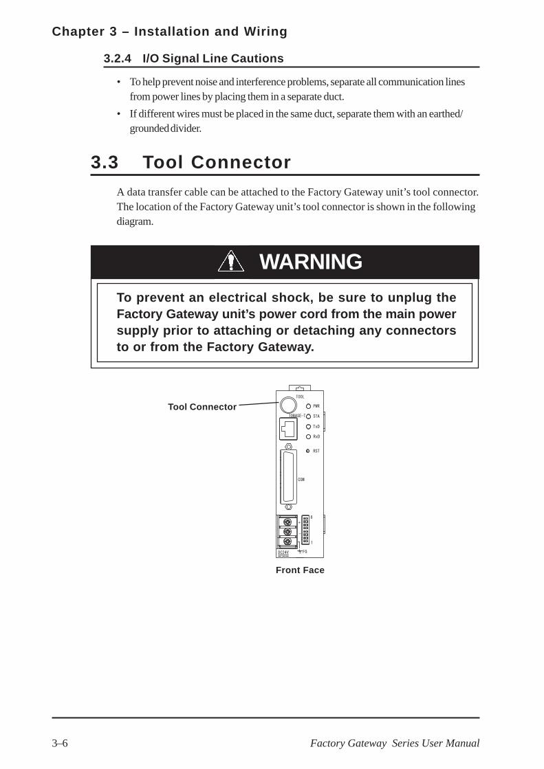
3.3 Tool Connector
A data transfer cable can be attached to the Factory Gateway unit’s tool connector.The location of the Factory Gateway unit’s tool connector is shown in the followingdiagram.
WARNING
To prevent an electrical shock, be sure to unplug theFactory Gateway unit’s power cord from the main powersupply prior to attaching or detaching any connectorsto or from the Factory Gateway.
Tool Connector
Front Face

3–7
Chapter 3 – Installation and Wiring
Factory Gateway Series User Manual
Ethernet Interface
3.4 Ethernet Cable Connector
The Factory Gateway Ethernet interface is IEEE802.3 compliant, and transmits data at10 Mbps. The Ethernet connector’s location is shown below.
Pro-face strongly recommends that a trained engineer installyour Ethernet network.
3.5 IP Address Settings
To set the Factory Gateway unit’s IP address, the 8 side face rotary switches are used.To set these switches, you must first remove the right face Rotary Switch Cover. Thefactory settings are all “0”.
Also, the Factory Gateway unit’s IP address is set using HEX.
The example below uses an IP address (DEC) of 192.168.0.1.
Decimal 192 168 0 1
Hexadecimal C0 A8 00 01
Rotary Switch Settings
IP Address
• Be sure to enter all IP address settings prior to connectingthe Factory Gateway unit to the power supply. If power isconnected to the Factory Gateway unit prior to settingthese switches, a communication (2-Way feature) error willoccur. In this case, please disconnect the Factory Gate-way unit’s power supply, set these switches, and recon-nect the power supply.

Chapter 3 – Installation and Wiring
3–8 Factory Gateway Series User Manual
• The “Subnet Mask” and “Default Gateway” settings are not setvia these switches. They are set using the Pro-Server with Pro-Studio for Windows software and then sent to the Factory Gate-way unit.
See Pro-Server with Pro-Studio for WindowsOperation Manual.
• The IP Addresses should be set as follows:
00.00.00.01 -> 7F.FF.FF.FE (0.0.0.1 to 127.255.255.254)
80.00.00.01 -> BF.FF.FF.FE (128.0.0.1 to 191.255.255.254)
C0.00.00.01 -> DF.FF.FF.FE (192.0.0.1 to 223.255.255.254)
• After setting the IP Addresses, be sure to reattach the cover.
3.6 Dip Switch Settings
The Factory Gateway unit’s Dip Switches are used to set the following features:
- Startup Transfer Mode
- Initialize Internal Memory
- Enable System Data Overwrite
- Enable 2-Way Driver Overwrite
The switches are numbered from one to eight,
from bottom to top. Factory settings are OFF.
*1 Normally, the Factory Gateway automatically changes to transfer mode. Todisable this, use DIP switch No.1. Also, be sure to set the switch back to OFFafter data transfer is completed. (If the PWR LED has changed to orange, the unithas changed to transfer mode.)
*2 Normally, the Factory Gateway reboots the system after data transfer. If SwitchNo.4 is left ON, every time the Factory Gateway transfers data, internalmemory’s data will be initialized (deleted). After you finish using Switch No.4, besure to set the switch to OFF before transferring data again.
*3 The System and the 2-Way Driver data can only be overwritten using GP-PRO-PBIII for Windows.
SwitchNo.
Feature ON OFF Note
1 Reserved Normally OFF
2 Reserved Normally OFF
3 Startup transfer mode*1 Startup in transfer
mode
Startup in on-line
modeNormally OFF
4 Initialize internal memory*2 Initialize internal
memory at start up
Do NOT initialize
memory at start upNormally OFF
5 Enable System Data Overwrite*3 Overwrite Enabled Overwrite Disabled Normally OFF
6 Enable 2-Way Driver Overwrite*3 Overwrite Enabled Overwrite Disabled Normally OFF
7 Reserved Normally OFF
8 Reserved Normally OFF

3–9
Chapter 3 – Installation and Wiring
Factory Gateway Series User Manual
• DIP switches are used to help the Factory Gateway recover from er-rors. Turning a switch ON forces that switch’s feature, such as initializ-ing internal memory, ON. To ensure the integrity of your data, pleasekeep these switches OFF when they are not being used.
• When changing the Dip Switches, be sure the tool/item you use is insu-lated, to prevent accidental damage to the unit.
3.6.1 Initializing Memory
Use the following steps to initialize the Factory Gateway unit’s memory.
1. Turn the Factory Gateway unit’s power supply OFF.
2. Set dipswitch 4 to ON.
3. Turn the Factory Gateway unit’s power supply ON.
4. The Factory Gateway unit’s power (PWR) LED will change from green to red.(approximately 10 seconds is required for initialization.)
5. The Factory Gateway unit’s power (PWR) LED will change from red to green.
6. After checking that the Factory Gateway unit’s power (PWR) LED has changed toorange, turn the Factory Gateway unit’s power supply OFF.
7. Set dipswitch 4 to OFF.
8. Turn the Factory Gateway unit’s power supply ON.
Dip Switch 4’s initialization can be used for Ethernet-related information (Serial commu-nication settings, Sub-net mask, distribution data, etc.), Network Project data, andscreen data. System program, 2-Way Driver, and PLC communication protocol datacannot be initialized.

Chapter 3 – Installation and Wiring
3–10 Factory Gateway Series User Manual
Memo

4–1Factory Gateway Series User Manual
Chapter4 Troubleshooting
1. Troubleshooting
2. Periodic Instection
4.1 Troubleshooting
The following information explains how to troubleshoot the Factory Gateway unit.The first steps should always be to check the following items.
• Is the Factory Gateway receiving the correct level of power?
• Is the Device/PLC receiving the correct level of power?
• Is the Factory Gateway correctly connected tot he Device/PLC?
• Is the Factory Gateway unit’s current protocol data correct for the type ofDevice/PLC that is connected?
For details about the Factory Gateway Configuration Tool Error Messages, refer tothe Factory Gateway Configuration Tool Operation Manual.
Factory Gateway Configuration Tool Operation Manual

Chapter 4 – Troubleshooting
4–2 Factory Gateway Series User Manual
4.1.1 LED Status Indicators
The Factory Gateway unit uses two LED indicators (PWR nad STA) to display thestatus of the Factory Gateway unit.The following table describes the problemsindicated by these LEDs, and gives suggestions for how to solve each problem.
PWR STA
Power supply is not operating.
Power terminal are not connected.
Power cord is cut or damaged.
Green Normally OFF If lit, a hardware error has occurred.
Red Normally OFF If lit, a hardware error has occurred.
Orange Normally OFF If lit, a hardware error has occurred.
OFF System Program Error
Next, turn dipswitches 5 and 6 ON and perform forced setup
using GP-PRO/PBIII for Windows. Be sure to also send 2-
Way Driver data.
Green No problem (Normal status)
System Error/ Screen
Data Memory Error
(ONLINE)
Turn Dip Switch #4 ON and restart the unit. After memory is
initialized, turn dip switch 4 OFF. Next, turn dipswitches 5
and 6 ON and perform forced setup using GP-PRO/PBIII for
Windows. Be sure to also send 2-Way Driver data.
Error (from externalsource)
Possibly interference or static from power line or input line
noise. Either separate these lines, or ground the unit's FG
terminal according to your country's regulations.
Factory Gateway Error If lit, a hardware error has occurred.
Incorrect IP Address Correct the unit's current rotary switch IP Address settings.
Sub-net Mask ErrorCheck the unit's rotary switch IP Address settings and the
Network Project's Sub-net Mask settings.
2-Way ErrorCheck is there is a problem with the Network Project's
Provider information.
2-Way Driver Error
Turn Dip Switch #4 ON and restart the unit. After memory is
initialized, turn dip switch 4 OFF. Next, turn dipswitches 5
and 6 ON and perform forced setup using GP-PRO/PBIII for
Windows. Be sure to also send 2-Way Driver data.
OFF Normally OFF If lit, a hardware error has occurred.
GreenNow initializing memory
(normal)
After initialization is completed, PWR turns orange and STA
turns green. Turn Dip Switch 4 OFF when completed.
Red
System Error/ Screen
Data Memory Error
(Now initializing memory)
Turn Dip Switch #4 ON and restart the unit. After memory is
initialized, turn dip switch 4 OFF. Next, turn dipswitches 5
and 6 ON and perform forced setup using GP-PRO/PBIII for
Windows. Be sure to also send 2-Way Driver data.
Orange2-Way Error
(Now initializing memory)
After initialization is completed, PWR turns orange and STA
turns green. Turn Dip Switch 4 OFF when completed. When
unit restarts, PWR and STA both turn green.
Red
Orange
Red
Green
Lamp NameProblem/Condition Possible Solution(s)
No powerOFF
OFF

4–3
Chapter 4 – Troubleshooting
Factory Gateway Series User Manual
PWR STA
OFF System Program Error
Next, turn dipswitches 5 and 6 ON and perform forced setup
using GP-PRO/PBIII for Windows. Be sure to also send 2-
Way Driver data.
Factory Settings(customer enters only
IP address)
Download Provider information and protocol data from Pro-
Studio.
Now transferring Unit is operating normally and sending data.
Error (from external
source)
Possibly interference or static from power line or input line
noise. Either separate these lines, or ground the unit's FG
terminal according to your country's regulations.
System Error/ Screen
Data Memory Error
(Data transfer error)
Turn Dip Switch #4 ON and restart the unit. After memory is
initialized, turn dip switch 4 OFF. Next, turn dipswitches 5
and 6 ON and perform forced setup using GP-PRO/PBIII for
Windows. Be sure to also send 2-Way Driver data.
Factory Gateway Error Possible hardware error.
Factory Settings(customer has not
entered IP address)
IP Address has not yet been entered. Set this data via the
unit's side-face rotary switches. After unit is restarted, PWR
turns orange and STA turns green.
Incorrect IP Address Correct the unit's current rotary switch IP Address settings.
Sub-net Mask ErrorCheck the unit's rotary switch IP Address settings and the
Network Project's Sub-net Mask settings.
2-Way Driver Error
Turn Dip Switch #4 ON and restart the unit. After memory is
initialized, turn dip switch 4 OFF. Next, turn dipswitches 5
and 6 ON and perform forced setup using GP-PRO/PBIII for
Windows. Be sure to also send 2-Way Driver data.
Lamp NameProblem/Condition Possible Solution(s)
Orange
Red
Orange
Green
When a hardware error occurs, please contact your local Pro-face distributor for service and repair.

Chapter 4 – Troubleshooting
4–4 Factory Gateway Series User Manual
4.1.2 Problem Solving
The following data explains possible solutions for Factory Gateway unit relatedproblems.
Connecting power causes the unit to initialize memory (PWR LED red -> orange)
CAUSE: Dip Switch #4 is turned ON.
SOLUTION: Turn Dip Switch #4 OFF and restart the Factory Gateway unit.
Unable to Transfer Data
CAUSE 1: Dip Switch #3 is turned ON, setting the unit in transfer mode.
SOLUTION: Turn Dip Switch #3 OFF and restart the Factory Gateway unit.
CAUSE 2: The protocol transferred to the Factory Gateway unit is incorrect.
SOLUTION: Check the Pro-Studio Status Monitor to confirm the type of PLCthe Factory Gateway is connected to. Send new protocol if necessary.
CAUSE 3: The Ethernet type’s protocol has been sent.
SOLUTION: The Factory Gateway is not designed to work with the Ethernetprotocol. Send the correct protocol to the Factory Gateway from theGP-PRO/PBIII for Windows software, using the forced setup.
CAUSE 4: The Subnet Mask and the Default Gateway have been initialized.
SOLUTION: When Disp Switch #4 is used to initialize the unit, the Subnet Maskand the Default Gateway are also initialized. To use these itemsagain, resend that data from Pro-Studio.
For information about the Sub-net Mask and the default FactoryGateway settings,refer to
Factory Gateway Configuration Tool Operation Manual
Also, the port number will revert to 8000 after initialization. Thus,if the Factory Gateway unit tries to use a port other than 8000, datatransfer cannot be performed.(Use of Port No. 8000 is recommended.)

4–5
Chapter 4 – Troubleshooting
Factory Gateway Series User Manual
4.2 Periodic Check PointsTo keep your Factory Gateway unit in its best condition, inspect the followingpoints periodically.
Operation Environment
• Is the operating temperature within the allowable range (0° C to 55° C)?
• Is the operating humidity within the specified range (10%RH to 90%RH, wetbulb temperature of 39° C or less)?
• Is the operating atmosphere free of corrosive gasses?
Electrical Specifications
• Is the input voltage (DC 19.2V to DC 28.8V) appropriate?
Related Items
• Are all power cords and cables connected properly? Have any become loose?
• Is the DIN rail holding the unit securely?
GP-Viewer Screens Cannot be Displayed
CAUSE: When data is sent from the Factory Gateway Configuration Tool,screen data is deleted.
SOLUTION: GP-Viewer screen data includes protocol data as well. However,if the Factory Gateway Configuration Tool software is used tochange the Factory Gateway unit’s protocol, the new protocol inthe Factory Gateway unit will be different from the previousprotocol. To prevent a possible data/protocol type conflict,however, the Factory Gateway Configuration Tool automaticallydeletes all existing Factory Gateway screen data prior to sending anew protocol. This, however, means that there is now no data forGP-Viewer to read out and display.
To prevent this type of problem, when using Pro-Viewer to viewFactory Gateway data be sure to always use GP-PRO/PRIII to sendboth screen and protocol data to the Factory Gateway unit.

Chapter 4 – Troubleshooting
4–6 Factory Gateway Series User Manual
Memo