Facility Earth Mesh Presentation PB
53
Lessons Worth Remembering Facility Earth Mesh (Grounding) Facility Earth Mesh (Grounding) 2 nd Workshop on Power Converters For Particle Accelerators June 14 – 16, 2010 P lB ll June 14 – 16, 2010 Facility Earth Mesh - 2nd Workshop on Power Converters for Particle Accelerators 1 Paul Bellomo
Transcript of Facility Earth Mesh Presentation PB

Lessons Worth Remembering
Facility Earth Mesh (Grounding)Facility Earth Mesh (Grounding)
2nd Workshop on Power Converters
For Particle Accelerators
June 14 – 16, 2010
P l B ll
June 14 – 16, 2010 Facility Earth Mesh - 2nd Workshop on Power Converters for Particle Accelerators 1
Paul Bellomo

Acknowledgements
P ti f th t i l h i i fPortions of the material herein is from:
Keith ArmstrongEMC specialist contractor based in the United KingdomEMC specialist contractor based in the United Kingdom 44(0) 1785 660247 [email protected]://www cherryclough comhttp://www.cherryclough.com
Ian McMichaelEMC specialist contractor based in [email protected]://www.pqsolutions.com.au
Ponciano RodriguezGroup Leader at SLAC
i @ l t f d d
June 14 – 16, 2010 Facility Earth Mesh - 2nd Workshop on Power Converters for Particle Accelerators 2

Topics
1. Reasons why I am here
2. FEM for safety
3. Reducing conducted and radiated noise
June 14 – 16, 2010 Facility Earth Mesh - 2nd Workshop on Power Converters for Particle Accelerators 3

1. Reasons Why I am Here
June 14 – 16, 2010 Facility Earth Mesh - 2nd Workshop on Power Converters for Particle Accelerators 4

Reasons Why I am Here
My experience in the past year
• A relatively new, operating synchrotron light source was experiencingi bl ff ti d t i iti d hi fnoise problems affecting data acquisition and machine performance
and availability. The problems were attributable to an inadequate FEM
• A recent review of a synchrotron light source upgrade plan revealed• A recent review of a synchrotron light source upgrade plan revealedmisconceptions about implementing the FEM grounding system
• Many people seem to think the personnel safety ground and “technicalMany people seem to think the personnel safety ground and technicalground” should be separate systems. This simply will not work and isunsafe
• A good FEM, in conjunction with other appropriate techniques, willprovide personnel safety and acceptable conducted and radiated noisesuppression
June 14 – 16, 2010 Facility Earth Mesh - 2nd Workshop on Power Converters for Particle Accelerators 5

Some Standards for Equipment and Personnel Safety
USAUSA
• NFPA 70 – 2008, National Electrical Code
• IEEE 80 – 2000, Guide for Safety in AC Substation Grounding
• IEEE 81 – 1983, Guide for Measuring Earth Resistivity
IEEE 142 2007 R d d P ti F G di f I d t i l• IEEE 142 - 2007, Recommended Practice For Grounding of Industrialand Commercial Power Systems (green book)
• IEEE 1100 – 2005, Recommended Practices for Powering andgGrounding Electronic Equipment (emerald book)
June 14 – 16, 2010 Facility Earth Mesh - 2nd Workshop on Power Converters for Particle Accelerators 6
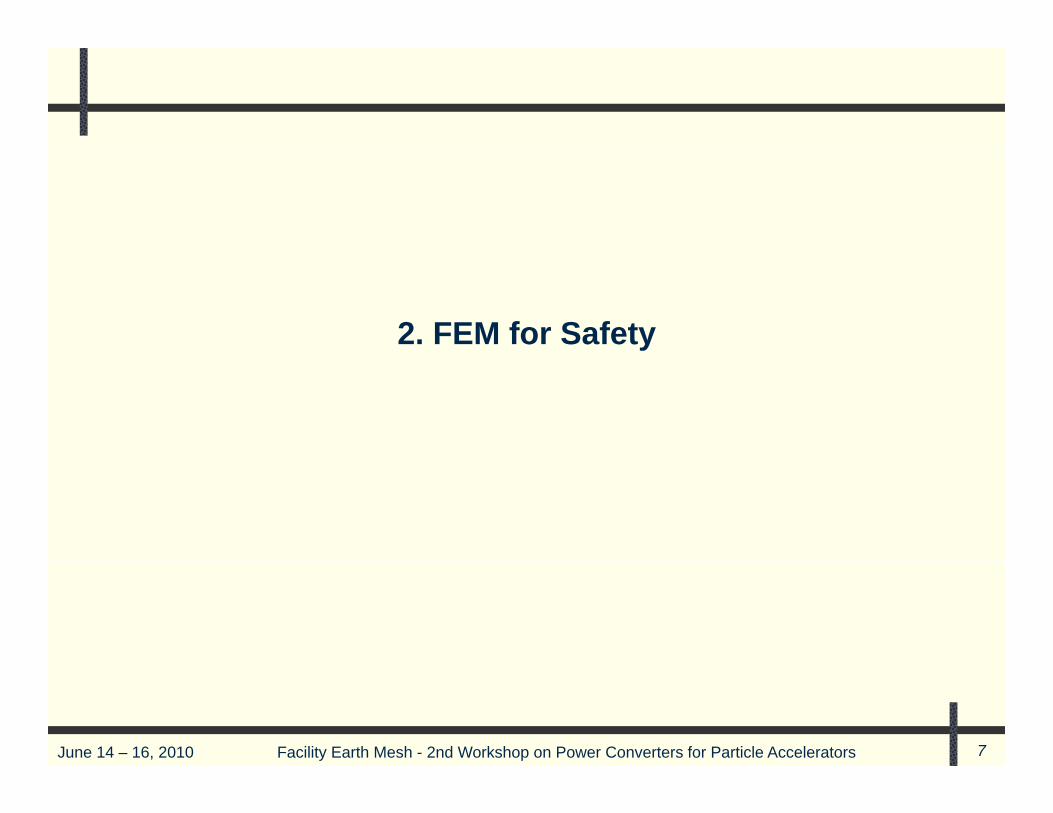
2. FEM for Safety
June 14 – 16, 2010 Facility Earth Mesh - 2nd Workshop on Power Converters for Particle Accelerators 7

The Shock Hazard
30 000 f t l l t i l h k id t h i th U S• 30,000 non-fatal electrical shock accidents each year in the U.S. -1,000 fatalities, 2/3 due to unsafe acts,1/3 due to unsafe equipment
• Shock hazards are found in AC distribution equipment panel boards• Shock hazards are found in AC distribution equipment, panel-boards,power supplies, magnets, modulators, pump motors and many othertypes of electromechanical equipment
• Body from hand to hand or hand to foot at 50V presents a highresistance. Voltages > 50V penetrate skin, body resistance is muchlower and unpredictable. Dangerous current flow is possiblep g p
• Shock hazard levels10 to 17mA let-go threshold30mA chest paralysis and suffocation75 to100mA heart fibrillation – need defibrillator in < 5 minutes. Knowwhere the Artificial External Defibrillators are located
June 14 – 16, 2010 Facility Earth Mesh - 2nd Workshop on Power Converters for Particle Accelerators 8

A Typical AC Distribution System
Substation 4.16kV Bus13.8 kV Bus Substation
4.16kV
4.16kV Bus13.8 kV Bus
• MV Systems Hi Z to ground
480V4.16kV
MV Systems Hi Z to ground• LV solidly grounded• Grounded at every level
F lt t d
208V:120V480V
Li t d f lt
• Faults to ground• Unbalanced lines• Lightning
ControlPS
480VLine to ground fault
g g
to powersupplies
PSPS
208V:120V
June 14 – 16, 2010 Facility Earth Mesh - 2nd Workshop on Power Converters for Particle Accelerators 9
Load Load Load

Step and Touch Potentials
Electric currents flow in the earthduring system fault or unbalancedcircuit conditions These currentscircuit conditions. These currentscause differences in the potentialsthe earth’s surface
Step potential can be experienced by a person simply by having their feet a“step” apart, even without contacting any grounded object
Touch potential is the difference between the ground potential where aperson is standing and the potential at the point where a hand (or otherbody part) is in contact with another structurebody part) is in contact with another structure.
Step and touch hazards are reduced by FEM (grounding) systems that limitthe potentials to 50V or less
June 14 – 16, 2010 Facility Earth Mesh - 2nd Workshop on Power Converters for Particle Accelerators 10

General Safety Concepts
• Keep Step and Touch Potentials to < 50V
• Combine all safety and technical ground systems into one, common FEM
June 14 – 16, 2010 Facility Earth Mesh - 2nd Workshop on Power Converters for Particle Accelerators 11

Separate Grounds are Unsafe and Do Not Provide EMC
‘Clean’ earths using single-point bonding
‘Clean’ grounds using single-point bonding
SafetyEMC
Lightning Lightning
‘Power’ earths using single-point bonding
Power grounds using single-point bonding
Other floorsOther floors
protection system (LPS)
g gprotection
system (LPS)
Ground floorGround floorMains distribution
Mains distribution
Item of equipment
1 3 N2 Bonding conductorBonding
conductor
LPS earth (mass) l t d
LPS earth (mass) l t d
SoilSoilHVHV Earth (mass) Earth (mass)
June 14 – 16, 2010 Facility Earth Mesh - 2nd Workshop on Power Converters for Particle Accelerators 12
electrodeselectrodeselectrode( )
electrode

Tying System Grounds Provides Safety but SP Grounds - Not EMC
Safety ‘Clean’ earths using single-point bonding
Clean grounds using single-point bonding
Safety
EMC
Lightning protectionLightning protection
‘Power’ earths using single-point bonding Power grounds using single-point bonding
Other floorsOther floors
protection system (LPS)
protection system (LPS)
Mains distribution
Mains distribution
Ground floorGround floorGround floorGround floor
Item of equipment
1 3 N2 Bonding conductorBonding
conductor
Earth (mass) electrodesEarth (mass) electrodesSoilSoilHVHV Earth (mass) l d
Earth (mass) LPS bonds to MESH-CBNLPS bonds to MESH
June 14 – 16, 2010 Facility Earth Mesh - 2nd Workshop on Power Converters for Particle Accelerators 13
( )Earth (mass) electrodeselectrode( )
electrodeLPS bonds to MESH CBN LPS bonds to MESH

FEM System Provides Good Safety and EMC
Other floorsOther floorsSafetyEMC
Lightning t ti
Lightning Meshed common bonding network,
MESH-CBN, for both ‘power’ and ‘clean’ earthsMeshed common bonding network,
MESH-CBN for both power and clean’grounds protection system (LPS)
protection system (LPS)
Ground floorGround floorMains distribution
Mains distribution
Item of equipment
MESH CBN, for both power and clean earths(also bonds services and ‘natural’ metalwork)
MESH CBN, for both power and clean grounds(also bonds services and all metalwork)
Bonding conductors
Bonding conductors
1 3 N2
Earth (mass) electrodesEarth (mass) electrodesSoilSoilHVHV
Earth (mass) l t d
Earth (mass) LPS bonds to MESH-CBN LPS bonds to MESH-CBN
June 14 – 16, 2010 Facility Earth Mesh - 2nd Workshop on Power Converters for Particle Accelerators 14
( )Earth (mass) electrodeselectrodeelectrode (additional bonds every 15-20m height in tall buildings)
LPS bonds to MESHCBN (additional bonds every 15-20m height in tall buildings)

Some FEM Details
S b t ti lSubstation, power supply, or other building type
This is a rudimentary FEM, provides safety but little EMC
Ground cable to Ring
2/0 to 500kcmil 8’ to 10’
Ground cable to Master Substation
June 14 – 16, 2010 Facility Earth Mesh - 2nd Workshop on Power Converters for Particle Accelerators 15
2/0 to 500kcmil stranded copper cable buried 18” to 24” deep
8 to 10
SLAC Rg=1s to 10s of ohms

Tie All Facilities FEMs Together
June 14 – 16, 2010 Facility Earth Mesh - 2nd Workshop on Power Converters for Particle Accelerators 16

Electrical Rack and Cabinet Bonding
T l bi t IT bi t
‘Frame bond’ conductors, 28 sq. mm, short and direct to underfloor ‘bonding mat’ or SRPP (area of MESH CBN)Bond cabinets to FEM
Telco cabinets IT cabinets
UPSComputer
flooring pedestal
Computer floor
pedestalpedestalpedestal
June 14 – 16, 2010 Facility Earth Mesh - 2nd Workshop on Power Converters for Particle Accelerators 17
Typical mesh size: 600mm square, connected to the BRC of the app ropriate EM ZoneTypical mesh size: 600mm square

3. Reducing Conducted and Radiated Noise
June 14 – 16, 2010 Facility Earth Mesh - 2nd Workshop on Power Converters for Particle Accelerators 18

Five Types of Electromagnetic Interference
1. Conducted Emissions - the EMI emitted into lines and connectionsby an electronic device
2 Conducted Susceptibility the EMI present on lines and connections2. Conducted Susceptibility - the EMI present on lines and connectionsthat affect a connected electronic device
3. Radiated Emissions - the EMI radiated by an electronic devicey
4. Radiated Susceptibility - the affect of radiated EMI on an electronicdevice
5. Electromagnetic Pulse – radiated EMI by lightning or atomic blast
June 14 – 16, 2010 Facility Earth Mesh - 2nd Workshop on Power Converters for Particle Accelerators 19

Some EMC Standards
USA
Federal Communications Commission (FCC) Code of Federal RegulationsCFR, Part 15, Sub-Part J, for Class A and B devices and equipment, , , q p
The FCC Class A requirements pertain to industrial equipment, while theClass B requirements are applicable to consumer equipment.
MIL-STD-461E and 462E Emissions and Susceptibility Standard forDefense Electronics. This standard sets the emissions and susceptibility(immunity) noise limits and test levels
International
There are many different standards used throughout the world. Therequirements and details vary but the concepts and intended end resultrequirements and details vary, but the concepts and intended end resultare the same as in the USA
June 14 – 16, 2010 Facility Earth Mesh - 2nd Workshop on Power Converters for Particle Accelerators 20

Conducted Emissions and Susceptability
EMI conducted onto lines by electrical, electronic and power conversionequipment
Typically 10 kHz to 30 MHz, covered by standards, but the noise frequency can be as low as the AC line frequency
Measured in V or dB V ( Reference: 1 V 0 dB )Measured in V or dB - V ( Reference: 1 V = 0 dB )
10measured VdB V 20* log
10dB V 20 log1 V
June 14 – 16, 2010 Facility Earth Mesh - 2nd Workshop on Power Converters for Particle Accelerators 21

EMI Emissions – Conducted levels
100100
8080
6060FCC Class A - IndustrialV
4040
FCC Class A Industrial
dB -V
FCC Class B - Consumer
2020
FCC Class B Consumer
0.01 0.1 1 1000.01 0.1 1 10
0
June 14 – 16, 2010 Facility Earth Mesh - 2nd Workshop on Power Converters for Particle Accelerators 22
0 0 0 00 0 0 0
Frequency in MHz

Conducted Emissions Test Equipment
S t l ith Li I d St bili ti N t k (LISN )Spectrum analyzers with Line Impedance Stabilization Networks (LISNs)• Filter and divert external AC line intrinsic noise from the EMI
measurementsI l t d d l th AC li hi h lt d t li t i t• Isolate and decouple the AC line high voltage and prevent line transientsfrom damaging spectrum analyzers and other sensitive test equipment
• Present a known, fixed impedance at RF frequencies to the power supplyd i t tundergoing test
June 14 – 16, 2010 Facility Earth Mesh - 2nd Workshop on Power Converters for Particle Accelerators 23

Differential Mode Noise
Conducted or radiated noise t t lionto system lines
V1= - V2
Magnitudes are equal
Phase difference is 180O
VDIFF = V1 – V2 = unwantedsignal
IDIFF = VDIFF / Rload flows into loadand FEM
June 14 – 16, 2010 Facility Earth Mesh - 2nd Workshop on Power Converters for Particle Accelerators 24
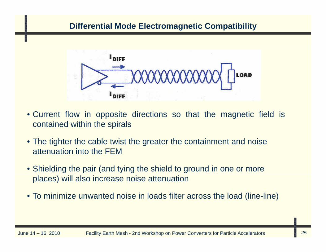
Differential Mode Electromagnetic Compatibility
• Current flow in opposite directions so that the magnetic field iscontained within the spirals
• The tighter the cable twist the greater the containment and noise• The tighter the cable twist the greater the containment and noise attenuation into the FEM
• Shielding the pair (and tying the shield to ground in one or more places) will also increase noise attenuation
• To minimize unwanted noise in loads filter across the load (line-line)
June 14 – 16, 2010 Facility Earth Mesh - 2nd Workshop on Power Converters for Particle Accelerators 25

Common Mode Noise
Produced as a result of simultaneous high frequency voltages on (+) and ( ) linesvoltages on (+) and (-) lines capacitively coupled to ground
V1 = V2 = VCOM1 2 COM
Magnitudes are equal
Phase difference is 0OPhase difference is 0
V3 = 0
I V *2 fCIc = Vcom*2fC
June 14 – 16, 2010 Facility Earth Mesh - 2nd Workshop on Power Converters for Particle Accelerators 26

Common Mode Electromagnetic Compatibility
• Current flows are the same magnitude and in the same direction so that the spirals have no effect on containing the magnetic fields
• The pair must be shielded and the shield tied to ground in one or more places for noise attenuation
• To minimize common mode voltages at the load, filter from each line to ground as shown above.
June 14 – 16, 2010 Facility Earth Mesh - 2nd Workshop on Power Converters for Particle Accelerators 27

Conducted Line Noise Filters
Delta inputp
Wye input
C fi ti C L Pi T• Configurations C, L, Pi, T
• Attenuation 20 to 70dB
• Filters both differential and• Filters both differential and common mode noise
June 14 – 16, 2010 Facility Earth Mesh - 2nd Workshop on Power Converters for Particle Accelerators 28

Reducing Conducted Noise on Other Systems / EquipmentMain AC Bus
PS PS PS I & CI & C I & C
• Separate noisy power supplies from sensitive I & C loads by Faraday -shielded transformers to attenuate common mode noise
• Place PS and I & C loads on dedicated busses separted by at least
June 14 – 16, 2010 Facility Earth Mesh - 2nd Workshop on Power Converters for Particle Accelerators 29
p yone transformer
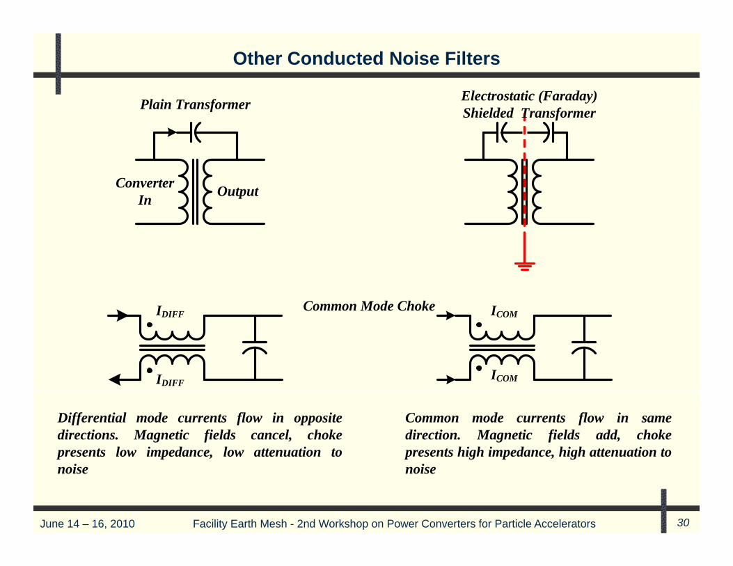
Other Conducted Noise Filters
Plain Transformer Electrostatic (Faraday) Plain Transformer Shielded Transformer
ConverterIn Output
IDIFF ICOMCommon Mode Choke
IDIFFICOM
Differential mode currents flow in opposite directions. Magnetic fields cancel, choke presents low impedance, low attenuation to
Common mode currents flow in same direction. Magnetic fields add, choke presents high impedance, high attenuation to
June 14 – 16, 2010 Facility Earth Mesh - 2nd Workshop on Power Converters for Particle Accelerators 30
noise noise

Radiated Emissions
EMI di t d f bl t f th t• EMI radiated from cables, transformers, other components
• Typically 30 MHz to > 1GHz. Cables and other equipment are effectiveradiators of frequencies above 30 MHz
• Measured in V / m or dB - V / m ( Reference: 1 V / m = 0 dB )
• Measured 3 m (Class B residential) or 30 m (Class A industrial) from theitti i t TV l t d ithi 3 f t i th hemitting equipment. TVs located within 3 m of computers in the home
and within 30 m in the industrial setting. Limits 100 to 200 V / m are1/10 of TV reception signal
• Industrial FCC Class A limits of 200 V / m are higher (less severe)because it is assumed that there will be an intervening wall betweenculprit and victim that will provide some shielding
• Test equipment are spectrum analyzers, rotating tables, conical and/orlog periodic antennas and anechoic chambers designed to minimizereflections and absorb external EMI
June 14 – 16, 2010 Facility Earth Mesh - 2nd Workshop on Power Converters for Particle Accelerators 31
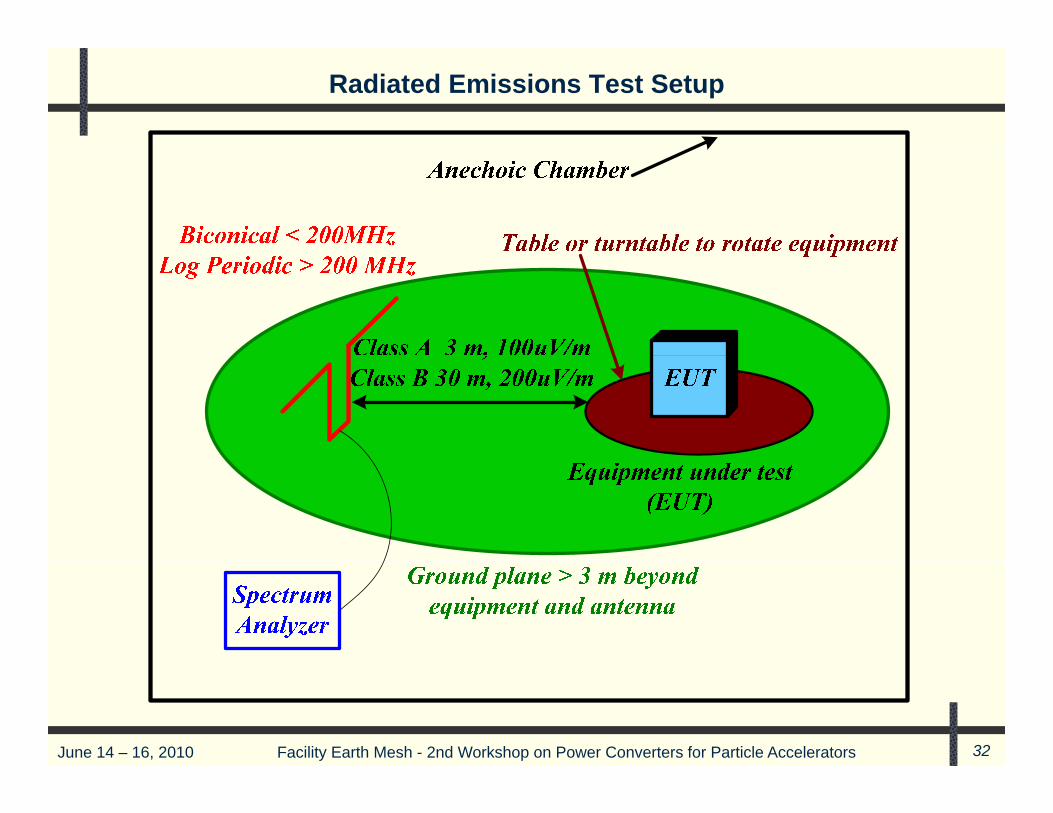
Radiated Emissions Test Setup
June 14 – 16, 2010 Facility Earth Mesh - 2nd Workshop on Power Converters for Particle Accelerators 32

Anechoic Chamber and Measuring Antenna
June 14 – 16, 2010 Facility Earth Mesh - 2nd Workshop on Power Converters for Particle Accelerators 33

Radiated Emissions - Faraday’s Induced Voltage Law
d φ d BV E dl A the magnitude and rate of change of flux density with time
the area of the loop cut by flux
V E dl Adt dt
dBVdt
V A
the area of the loop cut by flux
It can be shown for a single loop in air that the noise voltage is
V A
V 2* π* f * μ
* H * AnV 2 π f μ
Wherenoise voltage in volts
0 H A
V noise voltage in volts frequency in Hz permeability of free space ( )magnetic field strength in A/m
n
7 20
Vfμ 4* π* 10 N / ampH
magnetic field strength in A/m loop area in m
Minimize loop areas - run supply and return bus
2
HA
or cable conductors together
June 14 – 16, 2010 Facility Earth Mesh - 2nd Workshop on Power Converters for Particle Accelerators 34
Minimize loop areas - run supply and return bus or cable conductors togetherand twist cables whenever possible
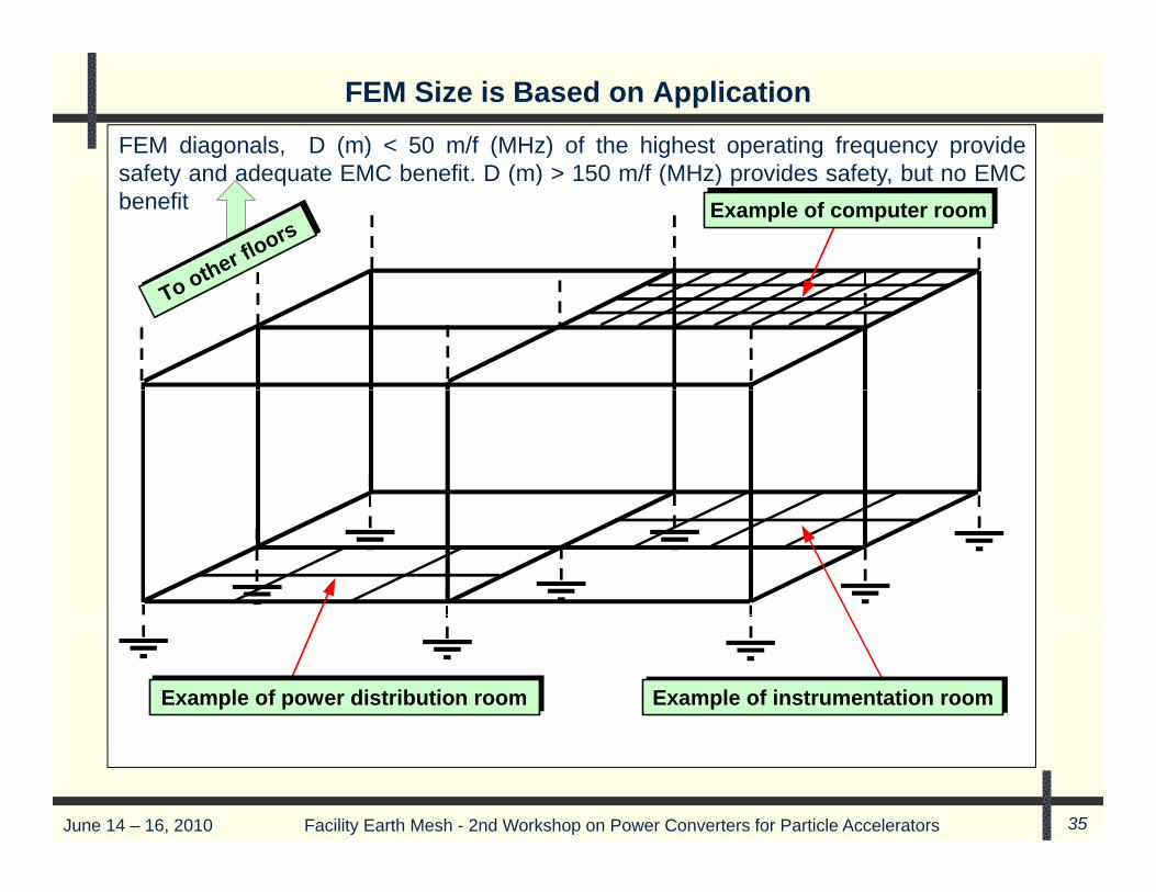
FEM Size is Based on Application
FEM diagonals, D (m) < 50 m/f (MHz) of the highest operating frequency providef t d d t EMC b fit D ( ) 150 /f (MH ) id f t b t EMC
Example of computer roomExample of computer room
o other floors
other floors
safety and adequate EMC benefit. D (m) > 150 m/f (MHz) provides safety, but no EMCbenefit
To otTo oth
Example of instrumentation roomExample of instrumentation roomExample of power distribution roomExample of power distribution room
June 14 – 16, 2010 Facility Earth Mesh - 2nd Workshop on Power Converters for Particle Accelerators 35

Creating the 3D FEM – Bond All Equipment to the FEM
MESH-CBN vertical elements (e.g. steel girders, re-bars)
MESH-CBN vertical elements (e.g. steel girders, re-bars)
MESH-CBN bonded to each floor's BRC at several placesMESH-CBN bonded to each
floor's BRC at several places
Cables routed close to MESH-CBN elements
l ti
Cables routed close to MESH-CBN elements
along entire route
along entire route
Cables and Cables and metallic services
RF-bonded at every BRC they
cross(Earthing bars
metallic services RF-bonded at
every BRC they cross
(E thi b(Earthing bars, plates, filters, SPDs, etc., not
shown)
(Earthing bars, plates, filters, SPDs, etc., not
shown)
June 14 – 16, 2010 Facility Earth Mesh - 2nd Workshop on Power Converters for Particle Accelerators 36
MESH-CBN’s horizontal elements (e.g. re-bars)
MESH-CBN’s horizontal elements (e.g. re-bars)
Example of a meshed RF Reference (e.g. SRPP, bonding mat)
Example of a meshed RF Reference (e.g. SRPP, bonding mat)

Creating the FEM – Cable Bond Network
B di d tMetal window and doorM t l i d d d Bonding conductors and BRCs
Bonding conductors and BRCs
Structural steelworkincluding reinforcementStructural steelwork
including reinforcement
Metal window and door frames, cladding,
roofing, etc.
Metal window and door frames, cladding,
roofing, etc.
Plumbing and pipework
Plumbing and pipework
Bonds across non- metallic pipe sections
Bonds across non- metallic pipe sections
Cable ducts, trays, conduits, etc.
Cable ducts, trays, conduits, etc.
p ppipe sectionsAir ducts, vents,
flues, chimneys, etc.Air ducts, vents,
flues, chimneys, etc.
Gratings, ladders, Gratings, ladders,Short bonding conductors used where direct metal to metal
Short bonding conductors used h di t t l t t l
June 14 – 16, 2010 Facility Earth Mesh - 2nd Workshop on Power Converters for Particle Accelerators 37
g , ,walkways, fences, etc.
Gratings, ladders, walkways, fences, etc.where direct metal-to-metal
fixings or welds are not practicalwhere direct metal-to-metal
fixings or welds are not practical

Creating the FEM
Paint removed to expose plated t l RF b d d 3/f
Paint removed to expose plated /fmetal, RF-bonded every 3/fmax
metres along the joint to the cable tray or duct
metal, RF-bonded every 3/fmaxmetres along the joint to the
cable tray or duct
( f in MHz)( f in MHz)
June 14 – 16, 2010 Facility Earth Mesh - 2nd Workshop on Power Converters for Particle Accelerators 38
f

Creating the FEM
U-bracket, bonded metal-to-metal at least every 3/fmax
metres along the joint
U-bracket, bonded metal-to-metal at least every 3/fmax
metres along the jointBase of duct or tray bent down and fixed to cabinet
3/fmax metres along the joint
Base of duct or tray bent down and fixed to cabinet
3/fmax metres along the joint
g j
(Continuous seam-weld or conductive gasket is best)
metres along the joint
(Continuous seam-weld or conductive gasket is best)
Double strap
Double strap
22 33
Single strapor wire bondSingle strapor wire bond
1133
44 f
June 14 – 16, 2010 Facility Earth Mesh - 2nd Workshop on Power Converters for Particle Accelerators 39
44 ( f in MHz)( f in MHz)

Radiated Emissions
Any component or cable > 1/20 wavelength (l) will be an efficientradiating or receiving antenna
Wavelength Vs Cable Lengths
Frequency 1/4 1/20
10 kHz 30 km 7500 m 1500 m = 59,000 in
100 kHz 3 km 750 m 150 m = 5,900 in
1 MHz 300 m 75 m 15 m = 590 in
10 MHz 30 m 7.5 m 1.5 m = 59 in
30 MHz 10 m 2.5 m 50 cm = 20 in
100 MHz 3 m 75 cm 15 cm = 6 in
June 14 – 16, 2010 Facility Earth Mesh - 2nd Workshop on Power Converters for Particle Accelerators 40
1 GHz 30 cm 7.5 cm 1.5 cm = 0.6 in

Low Impedance Returns Are Mandatory
Return conductors
• Above a few kHz resistance is not a factor, capactive and inductivereactances (impedance) dominatereactances (impedance) dominate
• Inductive reactance (impedance, 2 f L) is proportional to inductanceand frequency. Inductance, L, is proportional to length, and inverselyproportional to thickness and widthproportional to thickness and width.
• Want to reduce path length
• Thickness can only be increased so much because of skin effectThickness can only be increased so much because of skin effect
• Width can be increased indefinitely. However, wide conductors arestiff and not easily installed. Get around this by braiding the
d tconductors
June 14 – 16, 2010 Facility Earth Mesh - 2nd Workshop on Power Converters for Particle Accelerators 41

Low Impedance Returns Are Mandatory
SignalSource Load
I t d d
PowerSource
arc
IntendedReturn
NoiseArc NoiseArc
i i
g g
June 14 – 16, 2010 Facility Earth Mesh - 2nd Workshop on Power Converters for Particle Accelerators 42
Ig = Iarc *Zi / ( Zi + Zg) Zi >> Zg ; Ig Iarc Zi << Zg ; Ig 0

Conductor Comparisons for Low Impedance
Long wires are poor for RF, but help control LF (e.g. 50Hz)
Long wires are poor for RF, but help control LF (e.g. 50Hz) 44
Shorter wire length is better for RF
Shorter wire length is better for RFbette obetter for RF
Short, wide braid strap is better still for RF
Short, wide braid strap is b tt till f RF 22
33
better still for RFbetter still for RF
Short wide metal plates with Short wide metal plates with
22
pmultiple fixings are the best
Short wide metal plates with multiple fixings are the best 11
June 14 – 16, 2010 Facility Earth Mesh - 2nd Workshop on Power Converters for Particle Accelerators 43
But no bonding conductor is ever as effective at RF as multiple direct metal-to-metal bonds, especially seam-welding
But no bonding conductor is ever as effective at RF as multiple direct metal-to-metal bonds, especially seam-welding
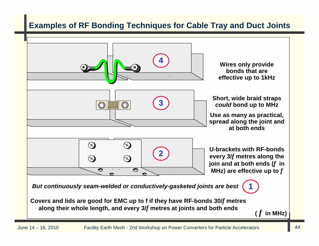
Examples of RF Bonding Techniques for Cable Tray and Duct Joints
Wires only provide bonds that are
effective up to 1kHz
44
effective up to 1kHz
Short, wide braid straps could bond up to MHz 33 p
Use as many as practical, spread along the joint and
at both ends
U-brackets with RF-bonds every 3/f metres along the join and at both ends (f in MH ) ff ti t f
22
But continuously seam-welded or conductively-gasketed joints are best
Covers and lids are good for EMC up to f if they have RF bonds 30/f metres
MHz) are effective up to f
11
June 14 – 16, 2010 Facility Earth Mesh - 2nd Workshop on Power Converters for Particle Accelerators 44
Covers and lids are good for EMC up to f if they have RF-bonds 30/f metres along their whole length, and every 3/f metres at joints and both ends
( f in MHz)
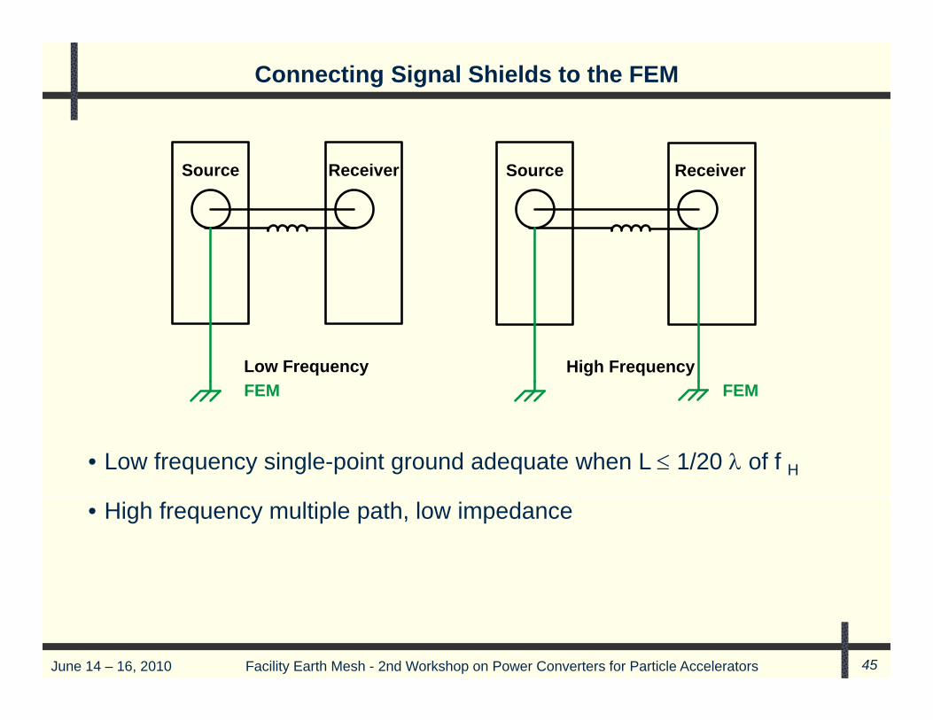
Connecting Signal Shields to the FEM
Source Receiver Source Receiver
Low Frequency High FrequencyFEM FEM
• Low frequency single-point ground adequate when L 1/20 of f H
• High frequency multiple path, low impedance
June 14 – 16, 2010 Facility Earth Mesh - 2nd Workshop on Power Converters for Particle Accelerators 45
AC Power Cables
Loops are undesirable, but unavoidable. Smaller loops are better. Makethe loops as small as possible. Bundle 3 phase cables and enclose indedicated gro nded metal cond its If possible t ist the cablesdedicated grounded, metal conduits. If possible, twist the cables.
Ensure that grounding cables closely follow the path of the input ACphase conductors to reduce magnetic loops Incorporate a safety groundphase conductors to reduce magnetic loops. Incorporate a safety groundcable in parallel with, or strapped to its AC power conductors
Connect the grounding conductors in multi-conductor AC power cables toConnect the grounding conductors in multi conductor AC power cables tothe FEM and the other end to the grounding bus in each switchgear,panel-board, or other premises or utilization equipment.
June 14 – 16, 2010 Facility Earth Mesh - 2nd Workshop on Power Converters for Particle Accelerators 46
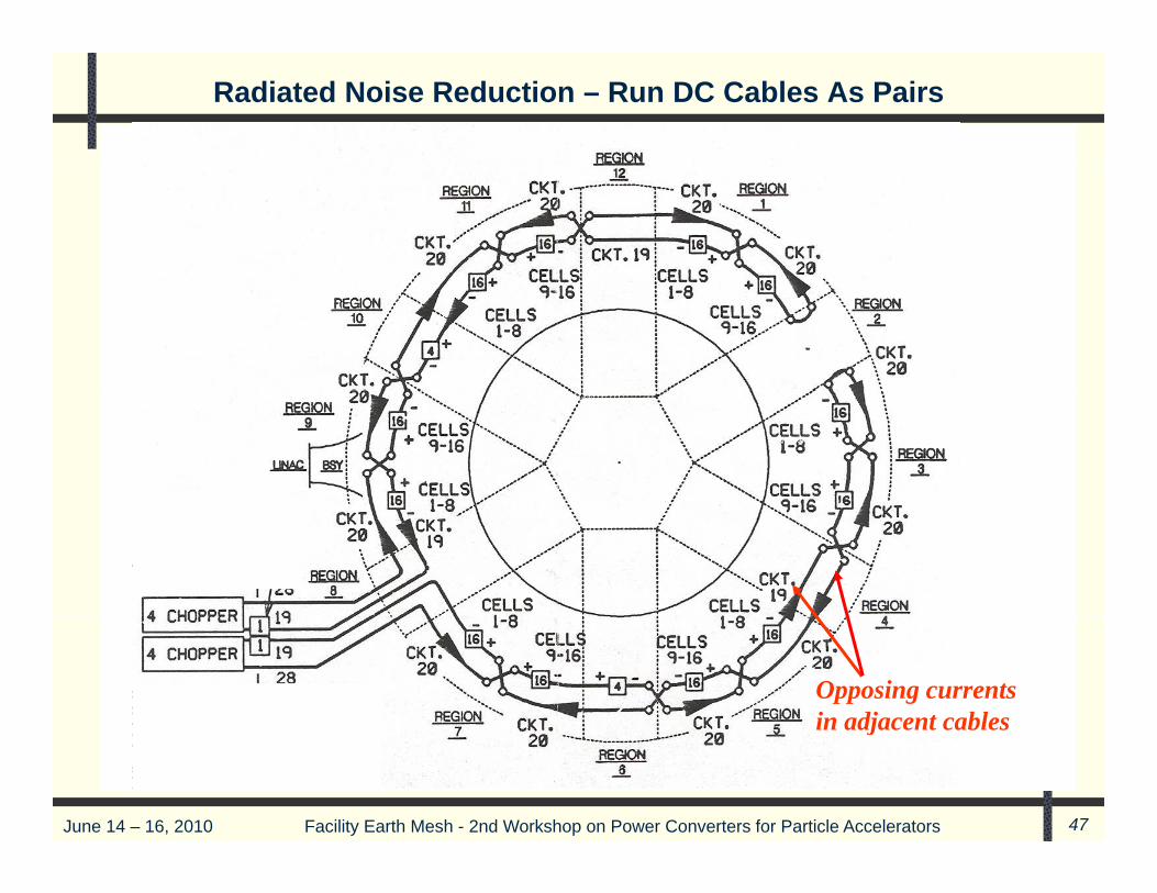
Radiated Noise Reduction – Run DC Cables As Pairs
Opposing currents in adjacent cables
June 14 – 16, 2010 Facility Earth Mesh - 2nd Workshop on Power Converters for Particle Accelerators 47
in adjacent cables

Minimize Cable Loop Area
NNLL
Bad EMC practiceBad EMC practiceBad EMC practice0V0V
The send and return conductors The send and return conductors
NNLL
should be in close proximity over their entire route
— ideally twisted together— for every kind of power
The send and return conductors should be in close proximity
over their entire route — ideally twisted together— for every kind of powerfor every kind of power or signal interconnection
— for every kind of power or signal interconnection
__++
June 14 – 16, 2010 Facility Earth Mesh - 2nd Workshop on Power Converters for Particle Accelerators 48
0V

Signal and Power Cables
Return Return Signal 1 Signal 2 Return Signal 3 Signal 4 Return …etc. is the minimum configuration that should be used for flat cable
Select EMC cable quality based upon the application.
A few extra ‘grounding’ conductors spreadconductors spread
throughout a wire bundle improves its EM
performance
Return Return Signal 1 Return Signal 2 Return Signal 3 Return…etc. gives the best EM performance that ribbon cable can achieve (but not as good as using twisted send/return pairs)
A large number of extra ‘grounding’ conductors spread throughout a wire bundle improves its EM performance even more (but still not as good as
June 14 – 16, 2010 Facility Earth Mesh - 2nd Workshop on Power Converters for Particle Accelerators 49
even more (but still not as good as using twisted send/return pairs)

Radiated Noise Reduction Techniques
( f f )Use shielded cables and enclosures (if necessary for interior controls)
http://www.lindgrenrf.com/
June 14 – 16, 2010 Facility Earth Mesh - 2nd Workshop on Power Converters for Particle Accelerators 50
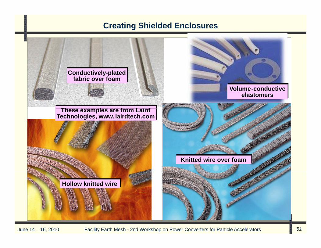
Creating Shielded Enclosures
Conductively-plated fabric over foam
Conductively-plated f b i ffabric over foamfabric over foam
Volume-conductive elastomers
Volume-conductive elastomers
These examples are from LairdTh l f L i dThese examples are from Laird Technologies, www. lairdtech.com
These examples are from Laird Technologies, www. lairdtech.com
Knitted wire over foamKnitted wire over foam
Hollow knitted wireHollow knitted wire
June 14 – 16, 2010 Facility Earth Mesh - 2nd Workshop on Power Converters for Particle Accelerators 51

Creating Shielded Enclosures
Examples of ‘spring Examples of ‘springp p gfingers’ (‘fingerstock’)
from Laird Technologies, www.lairdtech.com
Examples of spring fingers’ (‘fingerstock’)
from Laird Technologies, www.lairdtech.com
June 14 – 16, 2010 Facility Earth Mesh - 2nd Workshop on Power Converters for Particle Accelerators 52

Other Techniques – Concluding Remark
• Avoid air gaps in transformer/inductor cores. Use toroid windings forair core inductors
Wh ti l fib ti bl t l di it l• Whenever practical, use fiber optic cables to carry analog, digital orcontrol signals, instead of cables or other conductors. Fiber opticcables do not behave as accidental antennas, they provide galvanicisolation that completely ignores any electromagnetic disturbances atisolation that completely ignores any electromagnetic disturbances, atany frequency, and they can handle high data rates.
June 14 – 16, 2010 Facility Earth Mesh - 2nd Workshop on Power Converters for Particle Accelerators 53