Facilities Planning Approach for the Space Shuttle
11
The Space Congress® Proceedings 1971 (8th) Vol. 1 Technology Today And Tomorrow Apr 1st, 8:00 AM Facilities Planning Approach for the Space Shuttle Facilities Planning Approach for the Space Shuttle J. T. Rose Manager, Operations and Implementation, Space Shuttle Program, McDonnell Douglas Astronautics Company -Eastern Division Follow this and additional works at: https://commons.erau.edu/space-congress-proceedings Scholarly Commons Citation Scholarly Commons Citation Rose, J. T., "Facilities Planning Approach for the Space Shuttle" (1971). The Space Congress® Proceedings. 4. https://commons.erau.edu/space-congress-proceedings/proceedings-1971-8th/session-11/4 This Event is brought to you for free and open access by the Conferences at Scholarly Commons. It has been accepted for inclusion in The Space Congress® Proceedings by an authorized administrator of Scholarly Commons. For more information, please contact [email protected].
Transcript of Facilities Planning Approach for the Space Shuttle

The Space Congress® Proceedings 1971 (8th) Vol. 1 Technology Today And Tomorrow
Apr 1st, 8:00 AM
Facilities Planning Approach for the Space Shuttle Facilities Planning Approach for the Space Shuttle
J. T. Rose Manager, Operations and Implementation, Space Shuttle Program, McDonnell Douglas Astronautics Company -Eastern Division
Follow this and additional works at: https://commons.erau.edu/space-congress-proceedings
Scholarly Commons Citation Scholarly Commons Citation Rose, J. T., "Facilities Planning Approach for the Space Shuttle" (1971). The Space Congress® Proceedings. 4. https://commons.erau.edu/space-congress-proceedings/proceedings-1971-8th/session-11/4
This Event is brought to you for free and open access by the Conferences at Scholarly Commons. It has been accepted for inclusion in The Space Congress® Proceedings by an authorized administrator of Scholarly Commons. For more information, please contact [email protected].

FACILITIES PLANNING APPROACH FOR THE SPACE SHUTTLE
J. T. Rose Manager, Operations and Implementation
Space Shuttle ProgramMcDonnell Douglas Astronautics Company - Eastern Division
St. Louis, Missouri
ABSTRACT
In developing an overall facilities plan for the Space Shuttle program, it is important to recognize that manufacturing, development, and operations requirements cannot be independently developed. While it is true that specific requirements for each element can be developed independently, apply ing these requirements to candidate locations can only result in an optimized facilities plan when the appropriate interrelationships of all program elements are properly assessed. Starting with an understanding both of the Shuttle vehicles and of the overall assembly flow, this paper discusses the MDC study of the overall manufacturing, test, and operations requirements for facilities. It also demonstrates the various interrelationships that must be recognized and studied before a recommended facilities plan can be effectively developed.
INTRODUCTION
The Space Shuttle will require the use of numerous existing government and industrial facilities. In order to establish the optimal utilization concept, it is necessary to identify and study booster and orbiter requirements from the initial manufacturing process, through testing, to operations. Of parti cular importance is the definition of those commonalities which will result in total program costs reductions. For each vehicle, consideration must be given to many program requirements affect ing the total facility planning concept. One major requirement involves the implementation schedule, which must be compatible with the program milestones and, at the same time,must be realisti cally cognizant of the time necessary to design* ' construct* and activate the Shuttle facilities. Additionally, continuous analysis must compare a variety of techniques for vehicle handling, assem
bly, checkout, servicing, etc. to determine the most effective methods for the complete Shuttle system. One initial activity involves the defini tion of key facilities and corresponding interrela tionships. Such definition provides traceability for a specific requirement, as well as indicating its impact on other considerations. For each major manufacturing, development, and operation activity, a progressively detailed evaluation of existing facilities is required in order to deter mine site facility capabilities (size, location, constraints, etc.). Additionally, transportation systems (air, rail, road, water) are vitally important for the shipment of materials and assem blies to and from candidate locations. The availa bility or limitations of transportation systems will directly effect the amount of work accomplished at a particular site. Results of this evaluation thoroughly describe the capability of potential sites to support the Shuttle program.
SHUTTLE GROUND RULES
In developing the facility plan, a number of pro gram and contractor ground rules have been estab lished as depicted below which influence the pri mary objectives of this plan. o Program master schedule milestones o Reduce nonrecurring and recurring costs o Final assembly location must have horizontal
take off capability o Maintenance, launch, landing and turnaround at
same location o Initial horizontal flights will be from final
assembly site o Site evaluation study shall consider new and
existing siteso Two week (or less) ground turnaround o Launch rates 25 - 75 flights per year
11-75

o Maximum use of existing facilitieso Minimum exposure to adverse environmento Minimum assembly and checkout requirements at
the launch padTKe -program master schedule Identifies a series of . major milestones which effect the facility planning concept. In addition, Mjor emphasis has been placed on minimizing both nonrecurring end recurring cost* and on writing Mxlmum use of exist ing capabilities* From these* siterdlnant ground rules for etch of the three major phases have been established* Fur txMple, far the manufacturing phase?, ftllMtnttloA of redundancy and transporta bility *wr develQpwrit testing and operations Is considered essential for successful Implementation. lii the devtlqpment phase* test ooanonallty* usp of aircraft test methods, and multi-use of major test artlclts are fcef fraiiii rules. The wtjor Opera tional phasft rules are k^yed to two weeks* or less* ground turnaround, and 'to central Ized maintenance, liiiiiiciii,, iJii landl i| opeettt ons .
SIZE COMPARISON High Cross Range Oribter vs DC-101
Is Shown In Figures 1 and 2* the Shuttle vehicles are generally similar In size 'to present day
" aircraft* Considering the overall size of? IE COMPARISON
Siiillt Biisier is C-5A
FIGURE 1
those vehicles* It Is obvious that handling and transportation nust bo a primary oonslderation In developing the fid 11%' plan. During the nanufiac- turlng phase, the vehicles iiif bo partially assembled prior to shlpnant to a final asswfely site* Tho Major asoonblfos my bo Manuftcturod at different locations * or coribl nations of assoribllns •ty bo doslpatod fwr nanufttcturo at one location.
It-ill •¥ IIEKHT
mm mm MHGE iitii? EH mr WIGNT- i\\,m LI
ilFlGUiE 2
This can only be determined when manufacturing and, test requirements are defined, and schedule con siderations are., thoroughly analyzed* Figure 3 shows the major booster assemblies* This vehicle's
FINAL ASSEMBLYManufacturing Assenblf" Sequ ence - Booster
largest ndule Is the main 'liquid Hydrogen tank. Ulpn completion of manufacturing, the tank will be rotated to the horizontal position on a mobile transporter» and "tlhen Is moved to -the assem bly area. The mobile transporters provide the capability of adjusting the tank assembly position for mating of other modules, prior to mating of the LQg tank assenfcly, the transporter unit Is rewivtdt leaving the main assembly on Its .'landing
Subsequently, the Li(L tank and nose section whiles are natad "to the niiln assembly* l|pi COBH pletttn of this activity, a prime mover unit Is positioned wider the forward landing gear and the OMplete assembly Is preparcNl tor shlpwnt. Final assciiHf operations wl 11 consist prlaartly of tttichment of wing and fii asscrib11ts»
11-76
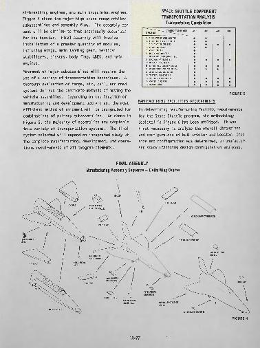
airbreathing engines, and main propulsion engines. Figure 4 shows the major high cross range orbiter subassemblies and assembly flow. The assembly con cept will be similar to that previously described for the booster. Final assembly will involve installation of a greater quantity of modules, including wings, main landing gear, vertical stabilizers, elevens, body flap, ABES, and main engines.
Movement of major subassemblies will require the use of a variety of transportation techniques* A thorough evaluation of barge, air, rail, and road systems defines the candidate methods of moving the vehicle assemblies. Depending on the location of manufacturing and development activities, the most efficient method of shipment will be designated for combinations of primary subassemblies. As shown in Figure 5, the majority of assemblies are adaptable to a variety of transportation systems. The final system selected will depend on integrated study of the complete manufacturing, development, and opera tions requirements of all program elements.
SPACE SHUTTLE COMPONENTTRANSPORTATION ANALYSIS
Transportation Capabilities^~~~^~~~~~--~-~-~--_TRANSPORTATION MODE
STRUCTURE ~~~~~~~~~^~"-~~~--~~_
1. CREW COMPARTMENT (ORBITERi2. FORWARD FUSELAGE (BOOSTER! 3. NOSE SECTION (ORBITERi4. CANARD (BOOSTER!5. WING (BOOSTER)6. DELTA WING (ORBITERi7. MAIN PROPULSION TANKS (B & Oi8. SECONDARY TANKS iB&Oi9, MAIN FUSELAGE (B & Oi
10. ENGINE PODS (ORBITERi DELTA11. CARGO DOORS (ORBITERi DELTA12. AFT FUSELAGE (BOOSTERi13. VERTICAL FIN (BOOSTERi14, VERTICAL FIN (ORBITERi15. CONTROL SURFACES16, DETAIL PARTS
BARGE AIR
** **
•
**
*••
RAL
•
•
ROAD
*
•
•••
MANUFACTURING FACILITIES REQUIREMENTS
FIGURE 5
In determining manufacturing facility requirements for the Space Shuttle program, the methodology depicted in Figure 6 has been utilized. It was first necessary to analyze the overall dimensions and configuration of both orbiter and booster. Once size and configuration was determined, a manufactur ing study utilizing design configuration analyses,
FINAL ASSEMBLY Manyfacturing Assembly Sequence - Delta Wing Orbiter
FIGURE 4
11-77

METHODOLOGY FOR DETERMINING MANUFACTURING FACILITIES REQUIREMENTS
FIGURE 6
material specification, process requirements, quan tity to be produced, and program schedules was conducted to determine how the structure should be broken down into manageable major subassemblies. Of necessity* ease of handling and fabrication were important considerations. At this point, the manu facturing requirements for each subassembly were developed. Detailed manufacturing breakdowns for each major subassembly were used to determine methods, tooling, manufacturing testing, and pro duction rates in accordance with the overall Mister Schedule and Shuttle Major Milestones.
From an analysis of manufacturing requirements, detailed facility requirements are developed. Such parameters as architectural, mechanical, electrical, and civic features are defined. Processing capa bilities, fabrication equipment, manpower, and skill availability are also necessary in establish ing facility needs.
Due to the uniqueness and size of many of the Shuttle vehicle subassemblies, a parallel activity of analyzing existing government and contractor facilities has been underway since the beginning of the Phase B program. This has been, and will con tinue to be, an iterative process, because only when the detailed manufacturing requirements are defined to adequate depth can a complete facility definition be accomplished* However, such a parallel facility investigation is quite important for a general assessment of the capabilities and limitations of existing facilities and their geographical locations.
As an example of the process defined above, the manufacturing breakdown: for the current booster vehicle configuration consists of the following
subassemblies:o main fuselage assemblyo forward fusel age/cockpit sectiono LOX tank fuselage sectiono center fuselage sectiono LH 2 tank fuselage sectiono aft fuselage/thrust structure sectiono L/H and R/H canard assemblieso L/H and R/H wing assemblieso L/H and R/H vertical finso L/H and R/H elevenso L/H and R/H rudderso thermal protection system
Taking the main liquid hydrogen (LH2 ) tank as an example, Figure 7 depicts how the major components are assembled. This tank, when completed, will be
LH2 TANK Manufacturing Assembly Sequence - Booster
* V=^
"V" RING SEGMENT /f \O2-REQUIRED ,
FID DOMEMSEMBLV x /J&. - *ff»,
FW) T*NK WSEMBLY
"Y" mm SEGMENT
CYLINDRICAL SECTION^REQUIRED
tSOGRIO CYLINDRICAL SEGMENT FINAL, ASSEMBLY
FIGURE 7
134 ft long by 34 ft in diameter, and will weigh approximately 48,550 Ib. It will be build princi pally of aluminum plate stock and forgings (con sisting of cylindrical tank skins, rings, end domes, and access port Jamb rings). Some of the manufac turing techniques required consist of: o isogrid pocket machining o stretch forming o power brake and roll 'forming o elevated temperature aging o chemical milling and processing o welding o X~rafin§ o pressure and leak testing
In general, the manufacturing sequence for thistank will consist of taking Machined parts after fo rm1n g» ag1ng, pro cess i ng > 1 ns pec11 on » etc »» and assembling then by welding to f&ra tank rings*
11-78

cylindrical skin, and end dome tank, sections. These tank sections, in turn, will be joined and welded in a specific sequence using a vertical weld tower; they will then be progressively pressure and leak tested, using a modified pneumostatic test technique.
From these typical manufacturing requirementsfor the L\\2 tanks, facility requirements (shown inFigure 8) have been developed. In addition to
MANUFACTURING AND TEST FACILITY REQUIREMENTS - BOOSTER LH 2 TANK
FINAL ASSEMBLY AREA. CLEAR HEIGHT. CRANE CAPACITY
SUBASSEHBLY AREA. CLEAR HEIGHT. PRECISION WELD & MACHINE SHOP
MANUFACTURING EQUIPMENT
TOOLING
TESTING
OFFICETRANSPORTATIONSTORAGE
10,000 SQ150 FT (V35 TONS28,000 SQMFTENVIRONRELATIVNUMERIC33 FT NIL33FTDIACHEMMILSTRECHPOWER BPOiER RAGING 0VWELDINGANODIC TX-RAY EQFORM DIEMACHINE
TRTICAL ASSEMBLY TO»ER)
T
NTAL CONTROLLED 75° 5°F, 50*. 5*«HUMIDITYLY CONTROLLED SKIN MILL 112 FT « 90 FT BED)
S BORING MILLOTARY TABLEFACILITY
ESSHE (42 FT THROAT)LS
NS( 15 FT i 40 FT)QUIPMENT (WG 4 1.8,1HKS(15FT«40FT)PMENT (FIXED t PORTABLE)
TRIM FIXTURES»ELD FIXTURESHANDLING FIXTURESTRANSPORTATION DOLLYSPNEUMATIC TEST EQUIPMENT FOR PROGRESSIVE PROOF PRAND LEAK TESTING.
12,000 SQ FTBARGEADEQUATE FOR HAf STOCK 1 DETAIL PAflfS
FIGURE 8
square footage of floor space, clear height, and environmental needs for fabrication and assembly areas, specific manufacturing equipment is important in the facility analysis because of the size of the Shuttle vehicles and their components. As an example, the 33 ft boring mill and rotary table are significant items. In addition, machining, forming, processing, inspection, and test equipment must be capable of handling unusually large parts and assemblies. Also, as in all programs, tooling is extremely costly.
Taking individual manufacturing and facility requirements for each major subassembly, it is important to compare these with requirements for other major subassemblies, to determine similar or common requirements (for example, the similarity between the booster liquid hydrogen [LHg] and liquid oxygen [LOX] tanks). In addition, similari ties between booster and orbiter vehicles should be analyzed from a manufacturing and facilities requirement viewpoint to identify commonalities. From these comparisons and analyses, an optimal approach for manufacturing, facilities utilization, and logical manufacturing locations can be deter mined. However, until the manufacturing and
facilities approach is compared against the development testing and operations requirements, a total facilities location and utilization plan cannot be developed.
GROUND DEVELOPMENT AND VERIFICATION TEST FACILITIES REQUIREllNTf
Siting of ground tests must be considered within the total framework of planning efficient utiliza tion of facilities for the Space Shuttle program. Initially, individual test facility requirements may be established independently of facilities planning for other program activities. Figure 9 shows the study methodology for establishing specifications for individual test facilities.
METHODOLOGY FOR DETERMINING GROUND TEST FACILITIES REQUIREMENTS
SYSTEM 1 ___ REQUIREMENTS | 1
PROGRAMMATIC 1 __ ,
.SPECIFICATIONS | —— <
CONFIGURATION 1DESIGN ANO ——— ' ANALYSIS \
__ J TEST 1™ REQUWEiEim p
———
-^
REQUIRED TYPES & CONFIGURATIONS OF TEST ARTICLES
iMETHODS
iDATA ACQUIRED
I & TEST REQ'MTSSATISFIEDPER TEST
iTEST RATE AND REQ'DTEST TIME ESTIMATES
-1
-
TEST FACILITIES* REQUIREMENTS
DATA ACQUISITION
SAFETY SUPPORT & SERVICETIME FRAME
FIGURE 9
It should be noted that, prior to establishing test facility requirements, the actual test require ments for the Shuttle vehicles must be developed. Test requirements are established by a process of interrelating system requirements, programmatic considerations, pertinent specification, and infor mation resulting from design and manufacturing engineering activities. These requirements will continue to change (or will become more definitive) as more is known about the configurations, but it is important to establish a reference baseline in order to continue planning toward establishing facility needs. When test requirements are analyzed to determine required test articles, test methods to be used, data requirements, and test rates and time estimates, test facility requirements can then be established. These requirements, in general, will specify dimensions and access, performance, data acquisition, utilities, safety, support services, and scheduling criteria.
11-79

Through preliminary Studies using the above pro cesses, major testing activities for the Space Shuttle Phase C and D program have been identified (as outlined 1n.Figure 10). The testing activities,
RELATIONSHIPS OF MAJOR GROUND TEST ACTIVITIES TO OTHER PROGRAM ACTIVITIES
MAJOR STRUCTURAL TESTS - CANARD BOOSTER
HUORTnTWCMTWITIES
llHOTWIIttTflTllia....................................................
STRUCTURAL MATERIAL! I ELEMENTS DEVELOPMENT ANDDYNAMIC iNODfiX TEIIMTC ..............................................
WWM P'RQP'U'LUON INTEGRATION (WTH FLIGHT HARDWARE).....
ACH, OK, W|. MEI FUEL SUBSYSTEM DEDICATED TESTING.
KIE INSWitKTOlN COMPATIBILITY TESTING ......................
AVIONICS, ECLS, CREN SYSTEMS, ELECTRICAL POUER, HYDRAULICS, FLIGHT CREI ESCAPE SYSTEM. VEHICLE MTACHHEIIf /SEPAHATON SYSTEM DEDICATED TESTING .......
INTEGRATED VEHICLE TESTING STRUCTURAL LOADING & HORIZONTAL POSITIONAL LOf-LEVEL DYHAtHC RESPONSE .................................
SUBSYSTEMS INTEGRATION AND EMC ........ ......................
FIRST VERTICAL FLIGHT VEHICLE GROUND FIRING TEST..
ENGINEERING AND DESIGN
...X
........X
........X
........ X
........ X
...... ..X
...................
MANUFACTURING
MAJOR SUBASSEMBLIES
..........X
FINAL ASSEMBLY
....... X. ......
...... X
......X.......
FLIGHTTEST
HTO
.*...
VTO
.X
..X
..X
.X
FIGURE 10
by their very nature, tend to be aligned with other program activities. As an example, verification tests of airframe sections interrelate with the manufacture of the major vehicle airframe sub- assemblies. Generally, testing activities become less Independent and more interrelated with manu facturing/assembly and flight preparation as tine progresses and program development natures.
For each of the major test requirements depicted In Figure 10, preliminary test facility require ments have been .4jenerated through the processes outlined In Figure 9. To Illustrate one example of these test requirements, airframe sections verifi cation test articles and test types are depicted In Figure 11, Major dedicated structural test arti cles for the booster are: o rudder o elevono wing* and! fin with aft thrust structure o forward fuselage o main LHg tanko intertank section with canard o LCL tank section o nose and main landing gears o approximately 20 percent equivalent fay weight
of the vehicle thermal protection system
Our current program relies upon two validation concepts:(1) Laboratory verification testing with
dedicated hardware
LABORATORY TEST DEDICATED HARDWARE
TESTS©INFLUENCE
COEFFICIENT(?) DYNAMIC
RESPONSE3 SAFE LIFE/
cyclic©ULTIMATE,
LOAD©ACOUSTICS©NEAT
TRANSFER
T PI
STRy cTU.RE
§ W m OF THERMAL W PROTECTION SYSTEM
©
RUDDER A
©0© \̂v
/? ^^VELEVONyCf ^* /) WING &©@© (] ̂ S%%%%x*^^ 7 \ m/ |vJlJW
*'-..X^^aK /
STRUCTURE (JESSA
C ^^x. FORKARD FUSELAGE^v 7x ©®®1AIN iHj TANK V-X '•'-..^ /^
@© 3v^'
INTER TANK SECTION! CANARD "*""-; "^\© © © l|*k^*4j)
L02TAIiK.SECII01(D®
LANDING *• **"MB NOSE & MA NDECELERATION LANDING GEAR © ®
FIGURE 11
(2) (Flight hardware nondestructive testing For each test requirement area,, major test facility requirements are developed. The airframe sections verification test represents one such area, and test facilities requirements for each structural test article are presently being developed. As an example, the booster aft thrust structure, wing and fin assembly will require a facility capable of handling a test article 85 ft long, 102 ft wide and .60 ft high, with a test setup envelope of 140 ft long, 150 ft wide and 65 ft high. The low level dynamic response testing will, require approximately ten 100 lib force exciters. An aeroctynaHtc load simulation of up to 40fl! Ibf/ftr for the wing and. fin will be required. The thrust structure and landing gear backup structure will require appli cation of approximately fourteen 800 KIP point loads. The facility must provide a controllable source for internal pressurlzatlon of the fuel tank of the alrbreathlng engines In the wing test artl- cl e. The data acquIs1t1on requ I rements Indl cate 100 channels for loads measurement, 700 for strains, 400 for deflections,. 10 for pressure and. 100 fbr accelerations, The ability to acconpHsh cross- plotting and visual display of data will te n»ee$sary.
Utilities requirements include test load ruction points 1n the floor,, hydraulic and, electrical
11-80

power, cooling water and a 20 ton overhead crane. The facility must be capable of providing personnel safety against possible failure effects from test loads. Support and services Include transportation and handling equipment, machine shop, minor fabrication and assembly ship, -and nondestruc tive Inspection equipment, The time frame 1n the overall Shuttle schedule for testing occurs between January 1974 and May 1976,
The Information listed above 1s typical of the types of facility criteria needed In each of the testing areas to provide the requisite base for developing test facility requirements. Test facility requirements specified 1n these terms can then be correlated with other program plans and requirements to produce an overall Space Shuttle facilities utilization plan,
OPERATIONS REQUI REMENTSThe Phase B operations site'facility'planning began with a three-way study of potential locations, existing site capabilities, and Shuttle operations facility definitions. The general facilities definitions for a Shuttle launch site are shown in Figure 12, These serve as the bases for develop-
TYPICAL OPERATIONS SITE FACILITIESCARGO OPERATIONSPRE -LAUNCHMAINTENANCE (VEHICLES)LANDING FIELD AND TAXIIAYSSAFING FACILITYADMINISTRATIVE AND ENGINEERINGOFFICESFLIGHT CREI TRAININGORDNANCE TESTORDNANCE STORAGECLEANING AND CALIBRATIONINSTRUMENTATIONDATA PROCESSINGPROPELLANT PRODUCTION/STORAGEWAREHOUSINGFOOD SERVICEBASE MEDICAL
. BIOMEDICAL
. METEOROLOGICAL
. TRACKING
. GENERAL SHOPS
. MOTOR POOL« SECURITY. FIRE DEPARTMENT STATIONS.POWER STATIONS. WATER SUPPLY. BARGING. PHOTOGRAPHIC. GEODETIC. ROADWAYS. SEWAGE TREATMENT. SITE MAINTENANCE. CALIBRATION LABORATORY
. COMMUNICATIONS* SPECIAL REQUIREMENTS. LAUNCH CONTROL CENTER. MOBILE LAUNCHES 'TRANSPORTER(S). CRML£R*AY. LAUNCH PAO(S)
. FLAME TRENCH, DEFLECTORS. GAS SERVICE AREAS. PROPELLANT STORAGE
' .EMERGENCY EVACUATIONAND PROTECTION
* WATER STATION. POWER DISTRIBUTION. SYSTEMS EQUIPMENT AREAS. PAD HARD STAND. ACCESS ROADS. FiRE PROTECTION SYSTEMS
AREAS
FIGURE 12
ment of detail facility requirements. Once candi date locations are evaluated for their existing capabilities, a detailed analysis compares site capabilities to facility requirement definitions. This results in a cost and schedule estimate for adaptation of each candidate site for the Shuttle program. A major trade study 1s in progress, com paring particular sites against criteria which In clude safety, environment, performance* costs, etc.
The program requirements document established two weeks, or less, as the required time' for vehicle ground turnaround operations.. This period allows
flexible yearly launch rates of from 25 to 75 flights. Concurrent with the, site evaluation activ ity, a series of analyses and trade studies deter mined baseline methods for vehicle processing, testing, propel 1 ant loading, etc. These baselines, combined with manufacturing and development require ments, have been used in the development of the ground operations timeline to accomplish turnaround operations. This timeline will be used to determine the detail facility requirements needed to support all elements of the Shuttle program. A general example is the booster and orbiter maintenance cycle, defined in Figure 13. Basically, during
MAINTENANCE CYCLE
FIGURE 13this four and one-half day period, preventative and corrective maintenance will be accomplished on each vehicle. In support of this activity, the facility must provide the necessary area and services for several vehicles in various stages of maintenance. The facility area must also be able physically to house the majority of vehicles, as well as pro viding support work areas, shops, and offices. For the Shuttle booster, approximately 250,000 ft2 of usable area with 100 ft of clear overhead is required for this activity. For cargo loading, 35 ton overhead cranes (for maximum payloads) will be provided. The general area will include the usual! services including power, shop air, grounding, lighting, etc., as well as contractor and government furnished equipment. Additionally, another prime requirement includes the Haunch pads necessary to support the launch rate previously mentioned. Figure 14 presents the Shuttle high launch rate ground turnaround timeline. Based on this flow, It is necessary to have two launch pads. This quantity will support the maximum launch rate* while pro-
11*81

HIGH LAUNCH RATE VEHICLE FLOW
FIGURE 14vlding flexibility in the event of contingencies or rescue missions. The pad will be designed and equipped so that post-launch maintenance can be accomplished in 3 days or less. Compatibility with a five day work week operation is a requirement. Each pad will include a hardstand area encompassing the flame trench and deflector, equipment rooms, personnel protective areas, and propel!ant storage and service systems.
INTERRELATIONSHIPSThe preceding sections have outlined the MDC approachto defining facility requirements for manufacturing,testing, and operational development, viewed some what independently of each other. Once an adequate depth of understanding of the individual require-
1s achieved, definite interrelationships be- Identifiable. These most be analyzed,
reshuffled* reanalyzed, etc., until all program elenents can be optimized within the framework of current program requirements and groundrules. This optimization procedure will bear heavily on the selection of locations for performing certain manu facturing, tests, and operations.
Our study is now in this iterative phase. It is important in Phase B to provide as detailed baseline for facilities as possible. This baseline, with its supporting rationale, is essential to NASA in its preparation of recommendations for govern ment facility utilization.
Some of the more Important interrelationships whichmust be analyzed include:o final assembly location compared with other major
subassembly activities o final assembly and operations maintenance
requirementso main propulsion tank assembly and test o main propulsion integration testing with engine
delivery o individual subassembly and testing requirements
The geographical location of the final assembly site profoundly impacts the assembly location of many major subassemblies. Based on our current manufacturing planning, booster and orbiter final assembly consists primarily of integration of fuse lages, wings, rudders, airbreathers, etc., plus the associated vehicle level checks. This requires facilities which will provide a final assembly building with 300,000 ft2 of floor space, and a clear height of 90 ft, necessary checkout stations and equipment, along with a 10,000 ft long by 300 ft wide runway for taxi tests and first flight demonstrations.
If the final assembly site does not have barg ing capabilities, additional facilities are re quired, such as a 2,400,000 ft , 50 ft clear height subassembly building; 22,440 ft2 , 150 ft clear height vertical weld assembly and hydrostatic test facility; and additional test facilities to accom modate the following test requirements: For orbiter structural verification test; o left or right wing with aft fuselage and aft
section of the ll-L tank o center fuselage including center sections of
main propel!ant tanko forward fuselage with forward LOX tank section o cargo Compartment door For the booster structural verification test; o aft thrust structure with left or right wing
and fin assembly o LH2 tank o Interbank structure with left or right hand
canard o LOX tank
In addition, the dedicated propulsion tank struc tural verification testing will also be conducted from the final assembly location. If the final assembly location has water access, as little as 9 percent of the total manufacturing and test effort could be concentrated there. Without water access, approximately 58 percent of the total manufacturing and testing effort would have to be concentrated at the final assembly site.
11-82

Another relationship which must be considered 1s that existing between the operations facilities for maintenance and prelaunch checkout, and final assembly requirements. The maintenance building must be ready for occupancy in 1977, and must be approximately 513 ft long, 490 ft wide, and with a clear height of 100 ft* In addition, a 10,000 by 300 ft runway must be available, sinee-the launch site is also the primary landing site. The final assembly location (mentioned earlier) has similar requirements, except for the facility occupancy date. These requirements include the need of a landing field suitable for horizontal verification flight and flyout. The relatively short time span for total Shuttle manufacturing, as well as the unique facility size requirements, constitute an important relationship when considering combined usage. In addition, a reduction in ground support and test equipment may be realized, since some repetitive testing could occur for separate loca tions. This may prove to be a significant driver.
There are three alternate methods of meeting the requirements for main propulsion integration testing. These include a dedicated boilerplate tankage test system, flight hardware with a partial ly assembled vehicle, and flight hardware with a completely assembled vehicle. The major advantage to a boilerplate system would be early testing and minimal risk to flight hardware. This advantage is directly associated with engine delivery and the availability of flight-weight tankage. Assuming flight weight tankage availability to be compatible with engine delivery, then the use of a partial vehicle assembly could be as time-effective as, and less costly than, a boilerplate system. Utiliza tion of the operations launch pad could (for this testing) be more cost effective than constructing or modifying a dedicated test facility. This becomes a consideration only if the launch site and the fuselage assembly site have water access, or if the launch site and the final assembly site are landlocked and at the same Ideation, Similarly, if the launch site is landlocked, and the final assembly site has water, a completed vehicle would be flown to the launch site for propulsion testing following flight acceptance testing,' Here again>' the prime objective is timely testing, and engine delivery compatibility.
Vehicle main tank assembly and testing must be
viewed in two perspectives: booster and orblter separated, and booster and orbiter joined, Neces sary test equipment, tooling, bull-dings, equipment, and personnel must be analyzed to deter mine the cost effectiveness for one, or for than one location. Main tank assembly and test locations will depend on the location of major fuselage and final assembly operations, since trans portation modes, costs, and times are important in assessing the most cost effective approach.
Looking deeper into the buildup of the Individual subassemblies, and relating these to the structural test requirements in the development program, will provide additional insight into more cost effective grouping of hardware for manufacturing testing. As an example, Figure 15 shows the major structural component by itself. An examination of the pertin*
ORBITER Main Wing Structure
FABRICATION AMDASSEMBLY:
19 FT 1 IN. I 33 FT it 7 FT 6 IN.
8J50 LB PER SIDE
TITANIUM, BORON ALUMINUM
SPARS, RIBS, SKINS, AND STIFFENERS; HOG-OUTS
PERTINENT INTERFACES
. OUTER IING BOX MUST BE TESTED IN CONJUNCTION VTNMDC FURNISHED CENTER BOX CARRY THROUGH STRUCTURE AND IITH BOUNDARY CONDITION SIMULATION OF FORWARD ATTACH POINTS TO PROPELLANT TANK
. TEST CONDITIONS AND TEST SET-UP MUST CONSIDER ALL DESIGN REQUIREMENTS FOR BOUNDARY INTER ACTIONS IITH LEADING EDGE,WING BOX SKIN PANELS (T.P.S.), ELIVON AND ELEVON ACTUATOR (S) 4TT*CliENTS, iODY FLAP AND BODY FLAP ACTUATORS ATTACHMENTS
. VERIFICATION TEST ARTICLE NOT CONSIDERED REUSABLE FOR FLIGHT
. MANUFACTURING PROCESSES
MANUFACTURING TECHNIQUES . MACHINE SPAR CAPS AND RIBS . SUB-ASSEMBLE SPARS AND RIBS . MACHINE IING ATTACH FITTINGS . STRETCH FORM TITANIUM SKINS . ATTACH STIFFENERS TO MNG SKINS . ASSEMBLE SPARS, RIBS, FITTINGS,
AND STIFFENED SKINS TO COMPLETEMNG ASSEMBLY
FIGURE 15
ent structural test requirements and interfacesindicates that associated elements adjoining thewing box could greatly reduce the number of testsimulators and test equipment if they were developedas a unit or (at a minimum) commonly tested. Thefollowing list illustrates some potential groupingsof orbiter subassemblies pursuant to this type ofanalysis,o rudder - fino main wing structure - elevens - body flap - main
landing gear - wain landing gear doors o pose section - nose landln gear o engine thrust mechanism and- pod- engine doors o main/nose landing gear/doors o cargo door - radiator o thrust structure - rudder - fin • o speed brakes - body flap
11-83

From the above examples, it ts apparent that any overall facilities plan must be developed in relationship with launch site and final assembly locations, To determine potential alternate approaches for comparison In-the.selection process of a recomended plan, one must start with a launchsite, one or more potential final assembly loca-**vticms, and then trade off various alternates for the major and minor subassembHes, Then mother launch 'site location 1s silected and the process repeated. In this manner, the various options are controlled to a degree sufficient to provide ade quate visibility for developing alternate plans
^compatible with program objectives. In addition, the study of a site for Initial operational develop ment should not exclude the Idea of developing an additional launch site, or sites, after operational status is achieved. This consideration will effect the facilities and implementation requirements of respective sites.
Major emphasis in our planning is placed on defining those activitees requiring government facilities (and their associated costs and schedules) as well as those activities which can be conducted in existing contractor facilities. From our studies, we believe that water access to the final assembly location or locations should be a requirement. Such an access mode provides maxi mum flexibility In using existing government and contractor manufacturing and testing facilities, avoids an extremely high concentration of personnel, minimizes excessive peaks and valleys In different labor categories, and achieves flexibility of work distribution both nationally and Internationally.
This discussion has pointed out,only a few of themany interrelations and combinations between manufacturing, testing, and operations that must be.considered In developing a comprehensive facilities plan. Through our planning* we at HOC will definea. cost effective approach that will help ensure the success of the Shuttle program.
11-84