FACILITIES CRITERIA (FC) NAVY AND MARINE CORPS DESIGN ...
218
FC 1-300-09N 1 May 2014 Change 6, 9 July 2021 FACILITIES CRITERIA (FC) APPROVED FOR PUBLIC RELEASE; DISTRIBUTION UNLIMITED NAVY AND MARINE CORPS DESIGN PROCEDURES
Transcript of FACILITIES CRITERIA (FC) NAVY AND MARINE CORPS DESIGN ...
FC 1-300-09N 1 May 2014
Change 6, 9 July 2021
FACILITIES CRITERIA (FC)
APPROVED FOR PUBLIC RELEASE; DISTRIBUTION UNLIMITED
NAVY AND MARINE CORPS
DESIGN PROCEDURES

FC 1-300-09N 1 May 2014
Change 6, 9 July 2021
FACILITIES CRITERIA (FC)
NAVY AND MARINE CORPS DESIGN PROCEDURES
Any copyrighted material included in this FC is identified at its point of use. Use of the copyrighted material apart from this FC must have the permission of the copyright holder.
U.S. ARMY CORPS OF ENGINEERS NAVAL FACILITIES ENGINEERING SYSTEMS COMMAND (Preparing Activity) AIR FORCE CIVIL ENGINEER CENTER Record of Changes (changes are indicated by \1\ ... /1/) Change No. Date Location 1 1 Apr 2015 Added Building Information Management/Modeling
(BIM) Requirements to Chapter 12 Updated Drawing Requirements for Chapter 12 Updated Special Inspection Requirements Added eOMSI Facility Data Workbook to Design Phase Chapters
2 1 Sep 2015 Revised Posting of Controlled, Unclassified Information in Chapter 2, clarified signature requirements in Chapter 12, and updated BIM submittal requirements.
3 1 Apr 2018 Cybersecurity: added new paragraphs 1-4, 5-9, 13-5.3 and 14-3.3. Fire Protection: changes to or added new paragraphs 4-6, 5-8, 6-8, 7-5, 7-9, 17-14, 17-15. Low Impact Development: changes to 6-6.1, 19-1. Sustainability: changes to 5-3, 13-6, 14-4.3, 14-7, 15-2.1, 16-2.2, 16-5.2, 16-11, 17-3, 17-7.2, 19-1.1, 19-1.4. SI Definitions: 2-2.2. Changes to 12-3.6.1, 12-4.1, 13-3.4, 17-4.1, App. A and B, and other minor changes throughout.
4 14 Jun 2018 Revised Chap. 13 and Added App. D and Landscape Architecture requirements; coordinated minor changes throughout. Deleted Chapter 9 paragraphs for Success and PACES, and added AACE reference.
FC 1-300-09N 1 May 2014
Change 6, 9 July 2021
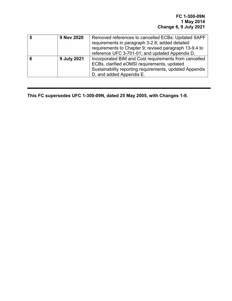
5 9 Nov 2020 Removed references to cancelled ECBs: Updated SAPF requirements in paragraph 3-2.8; added detailed requirements to Chapter 9; revised paragraph 13-9.4 to reference UFC 3-701-01; and updated Appendix D.
6 9 July 2021 Incorporated BIM and Cost requirements from cancelled ECBs, clarified eOMSI requirements, updated Sustainability reporting requirements, updated Appendix D, and added Appendix E.
This FC supersedes UFC 1-300-09N, dated 25 May 2005, with Changes 1-9.

FC 1-300-09N 1 May 2014
Change 6, 9 July 2021
This Page Intentionally Left Blank
FC 1-300-09N 1 May 2014
Change 6, 9 July 2021
FOREWORD Facilities Criteria (FC) provide functional requirements (i.e., defined by users and operational needs of a particular facility type) for specific DoD Component(s), and are intended for use with unified technical requirements published in DoD Unified Facilities Criteria (UFC). FC are applicable only to the DoD Component(s) indicated in the title, and do not represent unified DoD requirements. Differences in functional requirements between DoD Components may exist due to differences in policies and operational needs. All construction outside of the United States is also governed by Status of Forces Agreements (SOFA), Host Nation Funded Construction Agreements (HNFA), and in some instances, Bilateral Infrastructure Agreements (BIA.) Therefore, the acquisition team must ensure compliance with the most stringent of the UFC (replace w/ FC), the SOFA, the HNFA, and the BIA, as applicable. Because FC are coordinated with unified DoD technical requirements, they form an element of the DoD UFC system applicable to specific facility types. The UFC system is prescribed by MIL-STD 3007 and provides planning, design, construction, sustainment, restoration, and modernization criteria, and applicable to the Military Departments, Defense Agencies, and the DoD Field Activities. The UFC System also includes technical requirements and functional requirements for specific facility types, both published as UFC documents and FC documents. FC are living documents and will be periodically reviewed, updated, and made available to users as part of the Services’ responsibility for providing criteria for military construction. Headquarters, U.S. Army Corps of Engineers (HQUSACE), Naval Facilities Engineering Command (NAVFAC), and the Air Force Civil Engineer Center (AFCEC) are responsible for administration of the UFC system. Defense agencies should contact the preparing service for document interpretation and improvements. Technical content is the responsibility of the cognizant DoD working group. Recommended changes with supporting rationale should be sent to the respective service proponent office by the following electronic form: Criteria Change Request. The form is also accessible from the Internet site listed below. FC are effective upon issuance and are distributed only in electronic media from the following source:
• Whole Building Design Guide web site http://www.wbdg.org/ffc/dod/. Refer to UFC 1-200-01, General Building Requirements, for implementation of new issuances on projects. AUTHORIZED BY:
JOSEPH E. GOTT, P.E. Chief Engineer Naval Facilities Engineering Systems Command

FC 1-300-09N 1 May 2014
Change 6, 9 July 2021
FACILITIES CRITERIA (FC) REVISION SUMMARY SHEET
Document: FC 1-300-09N, Navy and Marine Corps Design Procedures
Superseding: UFC 1-300-09N, Design Procedures, 25 May 2005, with Changes 1-9
Description: This FC provides specific guidance on how and when to provide a project design deliverable for NAVFAC. This document is organized into design deliverables and design phases. Requirements for design deliverables, beyond or in more detail of what is already required by a Core UFC, are provided for NAVFAC-only. The requirements for when or to what extent these deliverables are provided are in the Phase chapters.
Reasons for Document: • Update procedures to coordinate with current commercial and government
standards, procedures, and governing UFC’s.
• Update sustainable documents and requirements to coordinate with UFC 1-200-02.
Impact: • Improve efficiency and consistency of design procedures across NAVFAC.
Unification Issues Design and Submittal procedures contained herein are pertinent to standards, software, and templates used, required, and unified within NAVFAC, and centered around the NAVFAC organization and operation. Procedures for NAVFAC may not work for USACE and Air Force operations due to organizational and operational differences. Similar uniform standardization and procedures are not available from the other Services.
FC1-300-09N 1 May 2014
Change 6, 9 July 2021
i
TABLE OF CONTENTS
INTRODUCTION ....................................................................................... 1
PURPOSE AND SCOPE. .......................................................................... 1
Organization of Document. .................................................................... 1
APPLICABILITY. ....................................................................................... 1
GENERAL BUILDING REQUIREMENTS. ................................................ 1
CYBERSECURITY. ................................................................................... 1
EXCEPTIONS. ........................................................................................... 2
REFERENCES. ......................................................................................... 2
GLOSSARY. .............................................................................................. 2
POLICY ...................................................................................................... 3
CRITERIA. ................................................................................................. 3
METRIC POLICY. ...................................................................................... 3
SI Definitions. ......................................................................................... 3
General Policy. ...................................................................................... 3
OWNERSHIP OF PROJECT DOCUMENTS AND DATA. ........................ 4
OPERATION SECURITY (OPSEC)........................................................... 4
OPSEC Review. .................................................................................... 4
Mission Information. ............................................................................... 4
Information Compilation. ........................................................................ 4
Sensitive or Critical Information. ............................................................ 4
REGISTRATION. ....................................................................................... 5
Certification. ........................................................................................... 6
PROHIBITION OF POSTING CONTROLLED UNCLASSIFIED INFORMATION DESIGN DELIVERABLES ON UNSECURED SERVERS. .............................................................................................. 6
DESIGN DELIVERABLES FOR NAVAL CONSTRUCTION FORCES -MARINE LOGISTICS GROUPS AND NAVY CONSTRUCTION BATTALIONS (SEABEES). .................................................................... 6
OVERSEAS LOCATIONS TRANSLATIONS. ........................................... 6
ROLES AND RESPONSIBILITIES ............................................................ 9
DESIGNER OF RECORD \1\(DOR)/1/. ..................................................... 9
Coordination with Command, Major Claimant, Region, and Activity. ..... 9
FC1-300-09N 1 May 2014
Change 6, 9 July 2021
ii
Coordination with Other Government Organizations. ............................ 9
Document Review and Checking System. ............................................. 9
Response to Review Comments. ........................................................... 9
Final Approval. ....................................................................................... 9
OTHER GOVERNMENT ORGANIZATIONS. .......................................... 10
Commander, 1st Naval Construction Division. ..................................... 10
Reviews for Health Hazards During Facilities Design Process. ........... 10
\6\Naval Information Warfare Center (NIWC) ...................................... 10
Civil Works. .......................................................................................... 10
Historic Preservation Compliance. ....................................................... 10
Overseas Cultural Resources. ............................................................. 11
NAVFAC Medical Facilities Design Office (MFDO). ............................. 11
Sensitive Compartmented Information Facilities (SCIF) and Special Access Program Facilities (SAPF). ...................................................... 11
COMMANDER, NAVFAC. ....................................................................... 11
DELIVERABLE: FIELD INVESTIGATION .............................................. 13
PURPOSE AND SCOPE. ........................................................................ 13
RESPONSIBILITIES................................................................................ 13
COORDINATION. .................................................................................... 13
TOPOGRAPHIC SURVEY. ..................................................................... 13
GEOTECHNICAL INVESTIGATIONS AND REPORT. ........................... 16
Existing Information. ............................................................................ 16
Foundation and Soils Investigation. ..................................................... 16
Geotechnical Report. ........................................................................... 17
Boring Logs. ......................................................................................... 18
Foundation and Site Preparation. ........................................................ 18
Airfield Pavement Evaluations. ............................................................ 19
FIRE PROTECTION INVESTIGATIONS AND SURVEY. ........................ 19
Utilities and Infrastructure. ................................................................... 19
Site and Building Surveys. ................................................................... 20
ENVIRONMENTAL REQUIREMENTS. ................................................... 21
DELIVERABLE: BASIS OF DESIGN ...................................................... 23
FC1-300-09N 1 May 2014
Change 6, 9 July 2021
iii
GENERAL REQUIREMENTS. ................................................................ 23
FORMAT. ................................................................................................ 23
KEY PROJECT CONTACTS. .................................................................. 23
BIM PROJECT EXECUTION PLAN (PXP). ............................................ 24
SUSTAINABILITY. .................................................................................. 24
Guiding Principles Validation. .............................................................. 24
Pre-award Commissioning Services. ................................................... 25
ANTITERRORISM (AT). .......................................................................... 25
GEOTECHNICAL. ................................................................................... 25
CIVIL. ....................................................................................................... 25
Existing Conditions. ............................................................................. 26
Demolition. ........................................................................................... 26
New Site Work. .................................................................................... 26
Water Supply. ...................................................................................... 27
Sanitary Sewer. ................................................................................... 27
Wastewater Treatment. ....................................................................... 27
Storm Drainage System. ...................................................................... 28
Stormwater Management..................................................................... 28
Erosion & Sediment Control. ................................................................ 28
Permits................................................................................................. 28
STRUCTURAL. ....................................................................................... 28
FIRE PROTECTION. ............................................................................... 29
Project Summary. ................................................................................ 29
Building Code Analysis. ....................................................................... 30
Life Safety Code Analysis. ................................................................... 30
Water Supply Analysis. ........................................................................ 30
Hydraulic Demand Analysis. ................................................................ 30
Active Fire Protection Features. ........................................................... 31
Host Nation Requirements. .................................................................. 32
CYBERSECURITY. ................................................................................. 32
DELIVERABLE: CALCULATIONS ......................................................... 33
GENERAL REQUIREMENTS. ................................................................ 33
FC1-300-09N 1 May 2014
Change 6, 9 July 2021
iv
COMPUTER GENERATED CALCULATIONS. ....................................... 33
FORMAT. ................................................................................................ 33
SUSTAINABILITY AND ENERGY. ......................................................... 33
GEOTECHNICAL REQUIREMENTS. ..................................................... 33
CIVIL. ....................................................................................................... 33
Low Impact Development (LID). .......................................................... 34
STRUCTURAL REQUIREMENTS. ......................................................... 34
Calculations and Test Reports for Antiterrorism. ................................. 35
Design for Lateral Forces. .................................................................... 35
Computer Generated Calculations. ...................................................... 36
FIRE PROTECTION CALCULATIONS. .................................................. 36
Hydraulic Demand Analysis. ................................................................ 36
Fire Pumps. ......................................................................................... 37
Special Systems. ................................................................................. 37
Fire Alarm/Detection and Reporting Systems. ..................................... 37
DELIVERABLE: DRAWINGS .................................................................. 39
GENERAL REQUIREMENTS. ................................................................ 39
BUILDING INFORMATION MANAGEMENT AND MODELING (BIM). .. 39
PRESENTATION. .................................................................................... 39
DRAWING NUMBERS. ........................................................................... 39
PROPER USE OF NOTES ON DRAWINGS. .......................................... 40
CODE COMPLIANCE SUMMARY SHEET(S). ....................................... 42
Building Code Site Plan \4\/4/. ............................................................. 42
Building Code Summary. ..................................................................... 42
Life Safety Code® Summary. .............................................................. 43
Life Safety Plans. ................................................................................. 43
CIVIL DRAWINGS. .................................................................................. 44
Cover Sheet, Drawing Index, Vicinity Map, Location Plan, Abbreviations, Legend, and Notes, or First Civil Sheet. ....................... 44
Demolition Plan. ................................................................................... 45
Site Plan. ............................................................................................. 46
Water and Sanitary Sewer Plan. .......................................................... 47
FC1-300-09N 1 May 2014
Change 6, 9 July 2021
v
Water, Storm, and Sanitary Sewer Profiles. ......................................... 47
Grading and Drainage Plan. ................................................................ 48
Site / Utility Details. .............................................................................. 48
LANDSCAPE ARCHITECTURAL DRAWINGS. ..................................... 49
Landscape Demolition Plan. ................................................................ 49
Landscape Site Plan. ........................................................................... 49
Landscape Construction Details. ......................................................... 50
Landscape Planting Plan. .................................................................... 50
Plant Material Schedule and Details. ................................................... 50
Landscape Irrigation Plan. ................................................................... 50
Irrigation Equipment Schedule and Details. ......................................... 50
GEOTECHNICAL DRAWINGS. .............................................................. 51
STRUCTURAL DRAWINGS AND NOTES. ............................................ 51
FIRE PROTECTION. ............................................................................... 52
Fire Sprinkler Systems. ........................................................................ 52
Gaseous Fire Extinguishing Systems. ................................................. 52
AFFF Foam Systems. .......................................................................... 52
Fire Suppression Detail Sheets. .......................................................... 53
Fire Alarm/Mass Notification System Plans. ........................................ 54
Fire Alarm/Mass Notification System Detail Sheets. ............................ 55
DRAWINGS PREPARED FOR OTHER GOVERNMENT ORGANIZATIONS. ............................................................................... 55
DELIVERABLE: SPECIFICATIONS ...................................................... 57
GENERAL REQUIREMENTS. ................................................................ 57
GUIDE SPECIFICATIONS. ..................................................................... 57
Unified Facilities Guide Specifications (UFGS). ................................... 57
Regional Guide Specifications. ............................................................ 58
Other Guide Specifications. ................................................................. 58
UFGS Selection Order of Precedence. ................................................ 58
Design-Build Performance Technical Specifications. ........................... 59
PROJECT PREPARATION POLICIES AND GUIDANCE. ..................... 59
UFGS Version Date. ............................................................................ 59
FC1-300-09N 1 May 2014
Change 6, 9 July 2021
vi
Editing of Specifications for Project. .................................................... 59
Standard Plates, Sketches, and Details. .............................................. 59
Unrestricted Bidding. ........................................................................... 59
Contract Parties. .................................................................................. 60
Facilities Electronic Operation and Maintenance Systems Information (eOMSI). .............................................................................................. 60
COORDINATION OF SPECIFICATIONS AND DRAWINGS. ................. 60
DBB Contract Order of Precedence. .................................................... 60
DB Contract Order of Precedence. ...................................................... 60
Coordination. ....................................................................................... 60
USE OF UFGS AND SPECSINTACT...................................................... 61
SPECIFICATIONS PACKAGE ORGANIZING STRUCTURE. ................ 61
Coversheet. ......................................................................................... 61
Contract Documents. ........................................................................... 61
Format. ................................................................................................ 62
General Requirements (Division 00 and 01) Specifications. ................ 62
Design-Build RFP. ............................................................................... 63
Project Reports. ................................................................................... 64
Combining Multiple Projects into One Bid Package. ............................ 65
DELIVERABLE: \6\COST ESTIMATES, RISK ANALYSIS, CONSTRUCTION SCHEDULES, AND VALUE ENGINEERING/6/.............................. 71
GENERAL REQUIREMENTS. ................................................................ 71
ESTIMATE CLASS STANDARDS AND REQUIREMENTS. ................... 71
ESTIMATE DEVELOPMENT AND SUBMITTAL REQUIREMENTS. ..... 72
User Generated Items. ........................................................................ 72
Level of Detail ...................................................................................... 73
Basis of \6\/6/Estimate. ........................................................................ 74
CONTRACT LINE ITEMS (CLINS).......................................................... 78
COST AND SCHEDULE RISK ANALYSIS (CSRA). .............................. 79
CONSTRUCTION SCHEDULE. .............................................................. 79
VALUE ENGINEERING STUDIES (VES) ................................................ 79
DELIVERABLE: CONTRACTING REQUIREMENTS ........................... 81

FC1-300-09N 1 May 2014
Change 6, 9 July 2021
vii
GENERAL REQUIREMENTS. ................................................................ 81
PROJECT INFORMATION FORM (PIF). ................................................ 81
SELECTION OF CLINS. .......................................................................... 81
OPTIONS AND ADDITIVES ON DRAWINGS. ........................................ 81
OPTION ITEMS. ...................................................................................... 82
ADDITIVE ITEMS. ................................................................................... 82
DEDUCTIVE ITEMS. ............................................................................... 82
PLANNED MODIFICATION ITEMS. ....................................................... 82
SYNOPSIS. ............................................................................................. 83
DELIVERABLE: DESIGN-BUILD REQUEST FOR PROPOSAL (RFP) ...................................................................................................................................... 85
GENERAL REQUIREMENTS. ................................................................ 85
DESIGN-BUILD REQUEST FOR PROPOSAL INTRODUCTION. .......... 85
DESIGN-BUILD REQUEST FOR PROPOSAL WEBSITE, FORMAT, AND DOCUMENTS. .............................................................................. 86
RFP Format. ........................................................................................ 87
Recommend Change to DB Documents. ............................................. 88
DESIGN-BUILD REQUEST FOR PROPOSAL DOCUMENT PREPARATION. ................................................................................... 88
Combining Multiple RFPs into One Bid Package. ................................ 88
Project Information Form (PIF). ........................................................... 88
RFP ELECTRONIC DELIVERABLES. .................................................... 88
DB DESIGN SUBMITTALS. .................................................................... 89
DESIGN AND CONSTRUCTION SUBMITTAL REQUIREMENTS. ........ 89
Locations of DB Submittal Requirements. ........................................... 90
Government Approval and Surveillance of DB Submittals. .................. 90
ELECTRONIC DESIGN DELIVERABLES (EDD) FORMAT ................. 93
SUMMARY. ............................................................................................. 93
ELECTRONIC DESIGN DELIVERABLES (EDD). .................................. 93
EDD FORMAT REQUIREMENTS. .......................................................... 93
Specifications. ...................................................................................... 94
\1\\2\Electronic Operation and Maintenance Support Information (eOMSI)/2/ Facility Data Workbook (FDW). ......................................... 94
FC1-300-09N 1 May 2014
Change 6, 9 July 2021
viii
Drawings. ............................................................................................. 94
\1\Preliminary Design Documents. ..................................................... 101
Final Design Documents. ................................................................... 101
Record Documents. ........................................................................... 104
NAVFAC Supported EDD Standard Components. ............................ 105
NAVFAC ELECTRONIC SIGNATURE REQUIREMENTS. ................... 106
General Requirements. ...................................................................... 106
Specific Software Requirements. ....................................................... 107
Wet-Signed Documents. .................................................................... 107
BUILDING INFORMATION MANAGEMENT/MODELING (BIM) REQUIREMENTS. ............................................................................... 108
BIM Definitions. .................................................................................. 108
Minimum Modeling and Data Requirements. ..................................... 109
Design Model. .................................................................................... 109
Record Model. ................................................................................... 111
Drawing and Model Progression. ....................................................... 112
BIM Submittal Requirements. ............................................................ 112
EDD MEDIA AND ORGANIZATION. .................................................... 113
General. ............................................................................................. 113
Minimum Final Submittal Requirements. ........................................... 113
Minimum Record Drawing Submittal Requirements. ......................... 114
PHASE: PRELIMINARY DESIGN: MCON ......................................... 115
GENERAL REQUIREMENTS. .............................................................. 115
PRELIMINARY DESIGN. ...................................................................... 115
INSTALLATION/PWD DD FORM 1391 ASSESSMENT. ...................... 115
PDA DOCUMENTATION. ..................................................................... 115
PDA Element. .................................................................................... 115
PDA File Naming Convention. ........................................................... 116
PRELIMINARY DESIGN CHARETTE. .................................................. 118
Format. .............................................................................................. 118
Participation. ...................................................................................... 118
IDENTIFICATION OF UNIQUE PROJECT REQUIREMENTS. ............. 119

FC1-300-09N 1 May 2014
Change 6, 9 July 2021
ix
DD FORM 1391. .................................................................................... 119
ROLES AND RESPONSIBILITIES. ...................................................... 120
PRELIMINARY PROJECT NARRATIVE. ............................................. 120
Description of Proposed Construction. .............................................. 120
Project Objectives. ............................................................................. 120
Site Analysis. ..................................................................................... 120
Building Requirements. ...................................................................... 121
Host Nation Requirements. ................................................................ 121
DISCIPLINE-SPECIFIC BASIS OF DESIGN. ....................................... 121
Building Systems. .............................................................................. 121
Site. ................................................................................................... 121
Cybersecurity Impact Level. ............................................................... 122
Ratio of Renovation Cost to Replacement Cost. ................................ 122
Narratives. ......................................................................................... 122
PRELIMINARY DRAWINGS. ................................................................ 122
COST ESTIMATE. ................................................................................. 124
SITE ENGINEERING INVESTIGATION (SEI). ...................................... 124
Utility Investigation. ............................................................................ 124
Subsurface/Geotechnical Investigations. ........................................... 125
Topographic Survey. .......................................................................... 125
Existing Building Surveys................................................................... 125
Hazardous Materials Investigation. .................................................... 126
Building Code Assessment of Adjacent Structures. ........................... 126
CALCULATIONS. ................................................................................. 126
Plumbing. ........................................................................................... 126
Mechanical. ........................................................................................ 127
Fire Protection. .................................................................................. 127
PHASE: \4\SCHEMATIC/4/ DESIGN SUBMITTALS (10-15%) ........... 129
GENERAL REQUIREMENTS. .............................................................. 129
DESIGN-BUILD \4\SCHEMATIC/4/ DESIGN SUBMITTAL. ................. 129
BASIS OF DESIGN. .............................................................................. 129
Geotechnical. ..................................................................................... 129
FC1-300-09N 1 May 2014
Change 6, 9 July 2021
x
Sustainability. ..................................................................................... 129
Cybersecurity. .................................................................................... 129
DRAWINGS. .......................................................................................... 129
Architectural. ...................................................................................... 130
Civil. ................................................................................................... 130
Landscape Architecture. .................................................................... 130
Electrical. ........................................................................................... 130
Fire Protection. .................................................................................. 131
Geotechnical. ..................................................................................... 131
\1\BIM PXP. ........................................................................................... 131
CALCULATIONS. ................................................................................. 131
SUSTAINABILITY. ................................................................................ 131
Third Party Certification (TPC). .......................................................... 131
CHARETTES AND FUNCTIONAL ANALYSIS CONCEPT DEVELOPMENT (FACD) STUDIES. .................................................. 132
Description. ........................................................................................ 132
PHASE: DESIGN DEVELOPMENT SUBMITTALS (35% - 50%) ........ 133
GENERAL REQUIREMENTS. .............................................................. 133
BASIS OF DESIGN. .............................................................................. 133
\1\\3\Sustainability. ............................................................................. 133
DRAWINGS. .......................................................................................... 133
Architectural. ...................................................................................... 133
Interior Design. .................................................................................. 133
Landscape Architecture. .................................................................... 134
Geotechnical. ..................................................................................... 134
Civil. ................................................................................................... 134
Structural. .......................................................................................... 135
Mechanical. ........................................................................................ 135
Electrical. ........................................................................................... 135
Fire Protection. .................................................................................. 136
\2\BIM DESIGN MODEL. ....................................................................... 136
OUTLINE SPECIFICATIONS. ............................................................... 136

FC1-300-09N 1 May 2014
Change 6, 9 July 2021
xi
\1\eOMSI Facility Data Workbook (FDW). ......................................... 137
CALCULATIONS. ................................................................................. 137
Structural and Geotechnical. .............................................................. 137
Civil. ................................................................................................... 137
Architectural. ...................................................................................... 137
Mechanical. ........................................................................................ 137
Electrical. ........................................................................................... 138
Fire Protection. .................................................................................. 138
Environmental Report. ....................................................................... 138
QUALITY CONTROL (QC) REVIEW AND DOCUMENTATION. .......... 138
Review. .............................................................................................. 138
Documentation. .................................................................................. 139
PHASE: PRE-FINAL DESIGN SUBMITTALS (100%) ........................ 141
GENERAL. ............................................................................................ 141
BASIS OF DESIGN. .............................................................................. 141
Geotechnical. ..................................................................................... 141
Sustainability. ..................................................................................... 141
DRAWINGS. .......................................................................................... 141
Civil. ................................................................................................... 141
Landscape Architecture. .................................................................... 142
Electrical. ........................................................................................... 142
/3/\2\BIM DESIGN MODEL. ................................................................... 143
SPECIFICATIONS. ................................................................................ 143
Sustainability. ..................................................................................... 143
Environmental\3\/3/. ........................................................................... 143
\1\eOMSI Facility Data Workbook. ..................................................... 143
CONTRACT SOLICITATION. ............................................................... 143
INTERIOR DESIGN. .............................................................................. 143
Structural Interior Design (SID). ......................................................... 144
FF&E.................................................................................................. 144
CALCULATIONS. ................................................................................. 144
Mechanical. ........................................................................................ 144

FC1-300-09N 1 May 2014
Change 6, 9 July 2021
xii
Electrical. ........................................................................................... 145
\1\STATEMENT OF SPECIAL INSPECTIONS. .................................... 145
DRAFT DD FORM 1354. ....................................................................... 145
FACILITY RECOGNITION PLAQUE..................................................... 145
DB RFP DEVELOPMENT. .................................................................... 146
OVERSEAS TRANSLATIONS. ............................................................. 146
QUALITY CONTROL (QC) REVIEW \6\AND DOCUMENTATION. ...... 146
Review. .............................................................................................. 146
Documentation. .................................................................................. 146
PHASE: FINAL DESIGN SUBMITTALS ............................................. 147
GENERAL REQUIREMENTS. .............................................................. 147
BASIS OF DESIGN. .............................................................................. 147
Geotechnical. ..................................................................................... 147
SUSTAINABILITY. ................................................................................ 147
TPC Design Review. .......................................................................... 147
DRAWINGS. .......................................................................................... 147
Plotstamp Record. ............................................................................. 148
Design–Build Shop Drawings. ........................................................... 148
\2\BIM DESIGN MODEL. ....................................................................... 148
SPECIFICATIONS. ................................................................................ 148
\1\eOMSI Facility Data Workbook. ..................................................... 149
Sustainability. ..................................................................................... 149
Environmental\3\/3/. ........................................................................... 149
Design-Build Design Submittal Specifications. .................................. 149
Report Source File. ............................................................................ 149
CONTRACTING DOCUMENTS. ........................................................... 149
INTERIOR DESIGN. .............................................................................. 149
Structural Interior Design (SID). ......................................................... 149
FF&E.................................................................................................. 150
CALCULATIONS. ................................................................................. 150
DRAFT FORM DD 1354. ....................................................................... 150
STATEMENT OF SPECIAL INSPECTIONS. ........................................ 150

FC1-300-09N 1 May 2014
Change 6, 9 July 2021
xiii
RFP........................................................................................................ 150
Report Source File. ............................................................................ 150
FIRE PROTECTION DESIGN COMPLIANCE DOCUMENT. ................ 151
QUALITY CONTROL (QC) REVIEW AND DOCUMENTATION. .......... 151
Review. .............................................................................................. 151
Documentation. .................................................................................. 151
Design-Build Quality Control. ............................................................. 151
Code Compliance Certification. ......................................................... 152
Host Nation Life Safety/Building Code Compliance Documentation. . 153
Geotechnical Report Translation. ...................................................... 153
PHASE: POST-DESIGN OR POST-RFP DEVELOPMENT SUBMITTAL REQUIREMENTS ....................................................................................................... 155
GENERAL REQUIREMENTS. .............................................................. 155
PRE-PROPOSAL/PRE-BID INQUIRIES AND REQUESTS FOR INFORMATION. .................................................................................. 155
CHANGE NUMBERS. ........................................................................... 155
COST ESTIMATE CHANGES. .............................................................. 155
CHANGE FORMAT. .............................................................................. 155
Language Format. ............................................................................. 156
Continuation Sheet. ........................................................................... 156
Proposed Change Sheet.................................................................... 156
Drawing Changes and Sketches. ....................................................... 158
PHASE: POST-CONSTRUCTION DOCUMENTS ............................... 163
PROJECT CLOSE-OUT. ....................................................................... 163
Interim Form DD 1354. ...................................................................... 163
Record Drawings. .............................................................................. 163
\1\BIM Final Record Model ................................................................ 163
Sustainability. ..................................................................................... 163
APPENDIX A REFERENCES .................................................................................. 165
APPENDIX B GLOSSARY ....................................................................................... 171
APPENDIX C SAMPLE DELIVERABLES ............................................................... 175
C-1 SAMPLE BID SCHEDULE FOR DESIGN-BID-BUILD PROJECT ... 175
FC1-300-09N 1 May 2014
Change 6, 9 July 2021
xiv
C-2 SAMPLE SYNOPSIS ........................................................................ 179
APPENDIX D DESIGN ESTIMATE CLASSIFICATION AND VALUE ENGINEERING STUDY REQUIREMENTS ................................................................. 181
D-1 PDA DESIGN-ESTIMATE. ................................................................ 185
D-2 VALUE ENGINEERING STUDY (VES) REQUIREMENTS. .............. 189
D-2.1 VE/VA Team Requirements. ............................................................ 189
D-2.2 VES Kick Off Meeting. ..................................................................... 189
D-2.3 Value Engineering Workshop (VEW).............................................. 189
D-2.4 VES Report. ...................................................................................... 191
D-2.5 Comprehensive Workshop VES Report. ........................................ 192
APPENDIX E BIM (MODELING) .............................................................................. 193
E-1 BIM - BASIS OF DESIGN SAMPLE TABLES. ................................. 193
E-2 QUALITY CONTROL CHECKS. ....................................................... 195
E-2.1 Overall Strategy for Quality Control. .............................................. 195
E-2.2 Quality Control Checks. .................................................................. 195
TABLES
TABLE 7-1 BIM AND FDW REQUIREMENTS. ............................................................ 39
TABLE 8-1 COMMONLY USED DBB UFGS DIVISION 00 AND 01 SECTIONS ........ 63
TABLE 8-2 COMMONLY USED DB RFP PART TWO UFGS DIVISION 01 SECTIONS ...................................................................................................................................... 64
TABLE 9-1 ESTIMATE CLASSIFICATION BY PROJECT PHASE ............................. 72
TABLE 9-2 BASIC ESTIMATE STRUCTURE AND LEVELS ON MII PROJECT ITEMS TAB ............................................................................................................................... 74
TABLE 11-1 DESIGN AND CONSTRUCTION SUBMITTAL SUMMARY .................... 90
TABLE 13-1 ELEMENT EXTENSIONS AND EXAMPLES ......................................... 117
TABLE 13-2 CSRA AND DCA FILE NAMING CONVENTIONS ................................ 118
TABLE 19-1 SPECIFICATION OR RFP CHANGES FORMAT .................................. 157
TABLE 19-2 DRAWING CHANGES FORMAT .......................................................... 158
TABLE D-1 DESIGN ESTIMATE CLASS COMPARISON FROM AACE RP 56-08. 181
TABLE D-2 MINIMUM PROJECT DATA AND DELIVERABLES.\5\ ......................... 185
FIGURES
FC1-300-09N 1 May 2014
Change 6, 9 July 2021
xv
FIGURE 8-1 SAMPLE TABLE OF CONTENTS FOR COMBINED DBB PROJECTS . 67
FIGURE 8-2 SAMPLE COMBINED DB AND DBB PROJECT .................................... 69
FIGURE 12-1 DRAWING PROGRESSION CHART DBB ............................................ 96
FIGURE 12-2 DRAWING PROGRESSION CHART DB ............................................... 96
\1\FIGURE 12-3/1/ NAVFAC SIGNATURES .............................................................. 107
FIGURE 12-4 DRAWING AND MODEL PROGRESSION DB\2\/2/ ............................ 112
FIGURE 13-1 PDA FILE NAMING CONVENTION ..................................................... 117
FIGURE 18-1 QUALITY REVIEW BLOCK. ................................................................ 151
FIGURE 19-1 SAMPLE AMENDMENT ...................................................................... 159
FIGURE 19-2 SAMPLE CONTRACT MODIFICATION .............................................. 161

FC1-300-09N 1 May 2014
Change 6, 9 July 2021
xvi
This Page Intentionally Left Blank

FC1-300-09N 1 May 2014
Change 6, 9 July 2021
1
INTRODUCTION
PURPOSE AND SCOPE.
This FC provides policy and standards for the design, development, and revision of project documents, including drawings, specifications, and Requests for Proposal, for facilities under the cognizance of NAVFAC. This FC has been developed to ensure consistency and clarity of project documents that form the basis of contracts for the design and construction of facilities.
Organization of Document.
This document is organized into design policy, roles and responsibilities, design deliverables, and design phases. The design deliverables chapters contain general requirements that apply throughout the design process. For the disciplines, additional information is provided only if it is not already in another UFC; thus a discipline paragraph may not be provided if the Core UFC already provides the requirements for that deliverable, or the level of completion of that deliverable. Core UFCs are defined and listed in UFC 1-200-01.
Detailed level of completion for each type of submittal, and for each discipline, only beyond what is specified in other UFCs, are included in each design phase.
APPLICABILITY.
This FC applies to projects where NAVFAC is the construction agent, as defined in DoDD 4270.5, for preparation of construction contract drawings, specifications, and Request for Proposals for shore facilities, and is applicable to both Design-Bid-Build (DBB) and Design-Build (DB) projects.
GENERAL BUILDING REQUIREMENTS.
Comply with UFC 1-200-01 and UFC 1-200-02. \3\Use UFC 1-200-02 /3/ in conjunction with UFC 1-200-01 and the UFC and government criteria referenced therein. UFC 1-200-01 provides applicability of model building codes and government-unique criteria for typical design disciplines and building systems, as well as for accessibility, antiterrorism, \3\ physical security, cybersecurity, high performance and sustainability requirements/3/, and safety. UFC 1-200-02 provides minimum unified requirements and coordinating guidance for planning, designing, constructing, renovating, and maintaining high performance and sustainable facilities that will enhance DOD mission capability by reducing total ownership costs. Use this FC in addition to UFC 1-200-01, UFC 1-200-02, and the UFC and government criteria referenced therein.\3\
CYBERSECURITY.
Plan, design, acquire, execute and maintain all facility-related control systems (including systems separate from a utility monitoring and control system) in accordance with UFC 4-010-06 and as required by individual Service Implementation Policy.

FC1-300-09N 1 May 2014
Change 6, 9 July 2021
2
Cybersecurity is implemented to mitigate vulnerabilities to all DoD real property facility-related control systems to a level that is acceptable to the System Owner and Authorizing Official. UFC 4-010-06 provides requirements for integrating cybersecurity into the design and construction of control systems. /3/
EXCEPTIONS.
Austere Requirements may be invoked on a per-project basis, and only by formal letter from Commander, Naval Installations Command (CNIC). Austere requirement options are included in UFC 4-610-01 FC 4-721-10N, FC 4-722-01N, and FC 4-740-02N.
REFERENCES.
Appendix A contains a list of references used in this document. The publication date of the code or standard is not included in this document. In general, the latest available issuance of the reference is used.
GLOSSARY.
Appendix B contains abbreviations.
FC1-300-09N 1 May 2014
Change 6, 9 July 2021
3
POLICY
CRITERIA.
Design Naval shore facilities in accordance with all Navy and Department of Defense (DoD) Criteria. DoD Design Criteria are available from the Whole Building Design Guide web site \5\(https://www.wbdg.org/ffc/dod)./5/ Design criteria include general criteria, as well as specific criteria on particular elements of the work \3\(such as/3/ Geotechnical Engineering) and facility types \3\(such as/3/ Bachelor Quarters). Design requirements are typically in the form of Unified Facilities Criteria (UFC). The contract will reference the specific requirements applicable to a particular project. Deviations from criteria must be approved by the NAVFAC Chief Engineer and in accordance with MIL-STD-3007.
METRIC POLICY.
Comply with MIL-STD-3007 for the use of SI in projects and criteria documents. NAVFAC policy is to use the metric system of measurement (International System of Units, SI) in planning and design criteria, Unified Facilities Guide Specifications (UFGS), and construction contract documents for all MCON/MILCON, BRACON, and family housing, regardless of acquisition method. See exception under the paragraph in this chapter entitled, “General Policy”.
SI Definitions.
\3\Hard Metric measurement: The actual size, capacity, or other measurement characteristic of a product is changed to a rational metric value. This measurement is used in the manufacturing process.
Soft Metric measurement: A simple arithmetical change from inch/pound to SI units, using a conversion factor, so that actual measurable characteristics remain virtually unchanged, or at least within the former tolerance limits.
Example: 4 foot by 8 foot panel is hard converted to 1200 mm by 2400 mm, or soft converted to 1219.2 by 2438.4 mm.1/3/
General Policy.
In accordance with Public Law 94-168, design and construction of new or renovated facilities must use the metric system of measurement, unless its use is impractical or is likely to cause significant inefficiencies or loss of markets to United States firms. Specify hard metric products unless such products are unavailable or uneconomical. Do not use dual units on drawings on any type of project. The design agent project manager is responsible for making the determination on whether or not to use the metric system of measurement on a project-by-project basis. Decisions to not use the
1 Definitions and example extracted from: Frishman, Bernard L./Loshak, Lionel/Strelka, Charles S. Metric Architectural Drawing. Canada: John Wiley and Sons, Inc., 1981, p. 11.
FC1-300-09N 1 May 2014
Change 6, 9 July 2021
4
metric system must be justifiable and documented in permanent project files. Comply with Facilities Engineering Command (FEC) process for determination of exception for the metric system.
OWNERSHIP OF PROJECT DOCUMENTS AND DATA.
The clauses set forth in DFAR 252.227-7023, Drawings and Other Data to Become Property of Government, DFAR 227.71, Rights in Technical Data, and DFAR 227.72 Rights in Computer Software and Computer Software Documentation, apply to all project documents and data.\6\
OPERATION SECURITY (OPSEC).
The OPSEC process provides a means of screening information prior to public release in order to prevent aggregation with other information, ultimately revealing DoD intentions or capabilities. Publicly released documents such as field investigations, reports, studies, Basis of Design, calculations, drawings, specifications, or Design-Build Request for Proposals (RFP) must not reveal sensitive or critical information.
OPSEC Review.
Include an OPSEC review by the requesting activity as part of the normal review process; prior to public release to identify any information that may require protection. Where applicable, modify details and identifying information in order to eliminate information the requiring activity has identified as sensitive or critical.
Mission Information.
DoD installations support units and missions that may be considered sensitive, critical or even classified. In addition, every DoD command performs a core, unclassified mission. Although unclassified, individual tasks required for a command to accomplish its mission may contain information that when pieced together with other information, reveal sensitive, critical, or even classified information.
Information Compilation.
The compilation of information that is individually unclassified may be classified as a result of the compilation. Classification requires a classification decision by an Original Classification Authority (OCA). NAVFAC is not an OCA.
Sensitive or Critical Information.
Sensitive or critical information is unclassified or controlled unclassified information (CUI) concerning the DoD activities, intentions, capabilities, limitations, or vulnerabilities. NAVFAC INSTRUCTION 3070.2 contains a critical information list. In addition, the following is provided to help avoid the disclosure of sensitive or critical information that must not be included in public ally releasable materials.

FC1-300-09N 1 May 2014
Change 6, 9 July 2021
5
• Do not identify a command if their mission or portion of their mission is considered critical or classified
• Do not identify a command’s mission or the mission supported by a facility if the mission is considered critical or classified
• Do not identify the capabilities or vulnerabilities of physical security or antiterrorism protective measures.
• Do not identify the location of a Sensitive Compartmented Information Facility (SCIF)
• Do not identify location of a Special Access Program Facility (SAPF)
• Do not identify Defense Critical Infrastructure
• Do not identify the location of Communications Security (COMSEC) Equipment.
• Do not identify Take Charge and Move Out (TACAMO) systems or mission.
• Do not identify Nuclear Command, Control and Communications (NC3) systems or mission
• Do not identify Military Strategic and Tactical Relay (MILSTAR) systems or mission
• Do not identify Advanced Extremely High Frequency (AEHF) systems or mission
• Do not identify purpose or frequency range of antennas or communication systems
• Do not identify Low Frequency (LF) or Very Low Frequency (VLF) transmission systems, missions, or specific location or site of the LF or VLF system.
Sensitive area locations such as SCIF and SAPF, may be labeled as "Controlled Area," “Secure Area,” or "Restricted Area” and may be shown on public releasable documents with the approval from the requesting activity’s Site Security Manager or Officer./6/
REGISTRATION.
Develop stateside project documents under the direction of a Registered Architect or a Professional Engineer currently licensed in accordance with FAR 52.236-25 Requirements for Registration of Designers. Develop foreign project documents under the direction of a Registered Architect or a Professional Engineer currently licensed by a United States state, commonwealth, or territory, the District of Columbia, or as permitted otherwise by the contract.
Each drawing must only be signed, sealed, and dated by the Registered Architect or the Professional Engineer who is registered to practice in the particular field involved for

FC1-300-09N 1 May 2014
Change 6, 9 July 2021
6
work depicted on that drawing, serves as the Designer of Record \1\(DOR)/1/ for that work, and complies with requirements of FAR 52.236-25. Sign Record Documents in accordance with Chapter 12, Electronic Design Deliverables (EDD) Format.
Certification.
Where special certifications are required for the design, certify in accordance with the contract and local requirements.
PROHIBITION OF POSTING CONTROLLED UNCLASSIFIED INFORMATION DESIGN DELIVERABLES ON UNSECURED SERVERS.
\1\Design deliverables may contain Controlled Unclassified Information (CUI) such as For Official Use Only (FOUO) or Department of Defense Unclassified Controlled Nuclear Information (DoD UCNI). The release of this type of information into the public domain may compromise an installation or facility’s Anti-Terrorism Force Protection (ATFP) or physical security protective measures. \6\Examples include the design analysis where the design basis threat (DBT) is an explosive weight and the location of a Sensitive Compartmented Information Facility (SCIF) or Special Access Program Facility (SAPF)./6/ \2\Protect deliverables, such as drawings, specifications, calculations, cost estimates, and other design related information, that contain CUI, in accordance with \6\DODM 5200.48. /6/ /2//1/
DESIGN DELIVERABLES FOR NAVAL CONSTRUCTION FORCES -MARINE LOGISTICS GROUPS AND NAVY CONSTRUCTION BATTALIONS (SEABEES).
Due to the nature of the work performed by the Marine Logistics Groups and the Seabees, the design deliverables for their use must be tailored for expedient construction. Deployed battalions may be in remote locations under austere conditions. Researching materials and transmitting submittals can be difficult, if not impossible. All materials and performance requirements should be specified on the drawings to the most practical extent. Specify materials available on the Federal schedule supply lists, the battalion’s supply schedules, or by product name. Avoid referencing codes or standards where possible, as reference materials may be difficult for the Battalion to obtain in the field.
OVERSEAS LOCATIONS TRANSLATIONS.
Construction drawings are required to be prepared in dual language at a majority of the overseas locations. Unless the contract scope indicates otherwise, translation of specifications is not required. Where dual language is required, the Host Nation A&E must accurately translate all required documents such that they are clear and comprehendible to the local construction community. The Host Nation A&E may also be contracted to translate Government furnished studies, surveys, geotechnical reports, product specifications, host country requirements or other technical documents

FC1-300-09N 1 May 2014
Change 6, 9 July 2021
7
prepared in a foreign language and serve as an interpreter when meeting with local officials and contractors.
\3\Include translations /3/with the Pre-Final (100%) submittal, and through project completion.

FC1-300-09N 1 May 2014
Change 6, 9 July 2021
8
This Page Intentionally Left Blank

FC1-300-09N 1 May 2014
Change 6, 9 July 2021
9
ROLES AND RESPONSIBILITIES
DESIGNER OF RECORD \1\(DOR)/1/.
Coordination with Command, Major Claimant, Region, and Activity.
Engage in and provide liaison with the Activity, and appropriate Activity personnel, as required by the contract, and during early design-development or RFP development.
The \1\ /1/DOR is responsible for architectural and engineering aspects of the project to ensure reasonable facility cost appropriate for the functions to be performed through design and RFP development.
Coordination with Other Government Organizations.
Coordinate design input and reviews with other Government organizations described in this chapter in paragraph “Other Government Organizations” and as required by the contract.
Document Review and Checking System.
The Document Review and Checking System (DrChecks) facilitates the formal review of complex project documents. DrChecks automatically tracks, collates, and measures technical discussions. Project documents can be uploaded into the project folders for download and review. Provide design reviews in DrChecks as required by the Contract. Contact the Government Project Manager to obtain registration information. DrChecks can be accessed at https://www.projnet.org.
Response to Review Comments.
Respond to comments in DrChecks or in accordance with Contract requirements. The DOR or Contractor is responsible for the resolution and incorporation of government comments into the project design. At each submittal, return and address previous review comments. Provide responses to review comments that clearly indicate what action is being taken to resolve the comment. If the comment was incorporated into the design, a response must so indicate; otherwise, provide acceptable technical justification for comments not being incorporated. \1\/1/Prior to the next submittal, contact the Government reviewer to discuss and resolve any comment that will not be incorporated.
The \1\/1/DOR is responsible for using professional judgment and technically evaluating user comments that suggest technical changes to design.
Final Approval.
FC1-300-09N 1 May 2014
Change 6, 9 July 2021
10
The \1\/1/DOR reviews and gives final approval for contract project documents prepared under their direction. The \1\/1/DOR must be registered in the discipline for the documents they approve as described in Chapter 2 in paragraph “Registration”.
OTHER GOVERNMENT ORGANIZATIONS.
Commander, 1st Naval Construction Division.
Projects scheduled for accomplishment by Naval Construction Forces are reviewed at an early Design Development stage by Commander, 1st Naval Construction Division, for construction methods and procedures.
Reviews for Health Hazards During Facilities Design Process.
For facilities projects that require industrial hygiene technical assistance and that involve potential health hazards such as toxic materials, non-ionizing radiation, noise, or other health hazards, consult the appropriate Naval Environmental Health Center (NEHC) for the activity. The NEHC activity is required to participate in design and RFP development reviews and reviews of plans, specifications, or RFP for these projects. The NEHC activity will ensure that engineering designs properly consider and provide for adequate environmental controls for the elimination of health hazards. Also use this review process for medical facility designs in excess of $1 million.
\6\Naval Information Warfare Center (NIWC)
NIWC provides reviews and design input for projects where NIWC is providing and installing equipment as identified in the DD Form 1391. The drawings of cable and equipment layout are often provided by NIWC to the \1\/1/DOR, for incorporation into the design. Coordinate closely with Government Project Manager and their NIWC representative to receive timely input and to reduce impact to design and construction schedules and project costs.
Projects, even if prepared by NIWC, must bear the standard NAVFAC title blocks and drawing numbers. On drawings that require NIWC approval, NIWC signature can be applied in the NAVFAC Signature Block in the supplemental location and the NIWC drawing cross reference number can be provided on the border sheet. NIWC may also need to review where project impacts an adjacent facility, such as electro-magnetic radiation from police stations or hospitals affecting antennae, transmitters, and receivers./6/
Civil Works.
NAVFAC approves drawings and specifications prepared for civil works subcontracts. Assign NAVFAC drawing numbers to civil works contract drawings, and approve and sign the drawings as "Satisfactory to" the prime contractor of the particular Navy industrial plant for whose use the facility is provided.
Historic Preservation Compliance.
FC1-300-09N 1 May 2014
Change 6, 9 July 2021
11
Section 106 of the National Historic Preservation Act requires Federal agencies to take into account the effects of their undertakings on historic properties that are eligible for listing in the National Register of Historic Places (NRHP). Historic properties may include archaeological sites, individual buildings, historic districts, landscapes, structures, objects, and traditional cultural properties. In accordance with established procedures at each installation, an action proponent files a National Environmental Policy Act (NEPA) Compliance Checklist plus a copy of the Work Request or Project Description with the Installation Cultural Resource Manager (CRM). The CRM then reviews the Project Description and determines whether the project has the potential to affect historic properties or whether it is exempt from Section 106 compliance. The CRM will then either record that the undertaking is exempt, or engage in consultation for Section 106 Compliance as required by 36 CFR 800.
Overseas Cultural Resources.
At Installations outside of the United States, coordinate with the applicable host nation regarding possible adverse effects to cultural resources. \1\/1/
NAVFAC Medical Facilities Design Office (MFDO).
Special coordination is required for coordination of medical facilities. Coordinate in accordance with /3/\3\UFC 4-510-01, Design: Medical Military Facilities.\5\
Sensitive Compartmented Information Facilities (SCIF) and Special Access Program Facilities (SAPF).
Special coordination is required for projects associated with a SCIF or SAPF. A designated, Government Site Security Manager (SSM) is assigned to the project. The SSM is responsible for the project’s security requirements and will prepare a Construction Security Plan (CSP), Fixed Facility Checklist (FFC) and the TEMPEST addendum to the FFC (referred to as the TEMPEST Form A) for the project. The SSM will submit these documents to the Accrediting Official (AO) for approval. The Designer of Record assigned to the project must assist the SSM in documenting the facility and site requirements necessary for the preparation of these documents. The AO-approved CSP, FFC and TEMPEST Countermeasure Review contains project requirements that must be incorporated into the project for the facility to be accredited. Refer to UFC 4-010-05 for additional information./5/
COMMANDER, NAVFAC.
Authority and responsibility for formal approval of drawings and specifications and RFPs by, or for, the Commander, NAVFAC, is vested in the Facility Engineering Command, Chief Engineer, \6\ Design Director (DC4), and PMEB Design Director. /6/
The level of approval and responsibility for Design-Build drawings and documents, submitted by the Contractor and signed by the Government, are defined in the RFP contract.

FC1-300-09N 1 May 2014
Change 6, 9 July 2021
12
This Page Intentionally Left Blank
FC1-300-09N 1 May 2014
Change 6, 9 July 2021
13
DELIVERABLE: FIELD INVESTIGATION
PURPOSE AND SCOPE.
The site approval process includes field investigation and verification. This early effort provides more defined project scope and cost, and can rule out a site. Many of the functions identified under this heading are also essential during the DD Form 1391 validation process to assure the project has the appropriate funding based on the scope of work. This section is not applicable for post-award design services of design-build contracts unless specifically addressed in the RFP.
RESPONSIBILITIES.
The Government installation planners are responsible for obtaining information required for project site approval prior to design. The \1\ /1/DOR must obtain all site and building data and investigate existing site conditions, utilities, and facilities as necessary to properly integrate the design of the project with existing conditions. Except as otherwise contracted, field investigations must include complete and accurate site investigation, topographic survey, and verification of location, \6\ownership,/6/ and availability of utility and drainage systems. When available, research existing \1\/1/ record drawings for information. Field verify \1\record drawings/1/ \1\/1/ information and other site features that may influence project design.
In a Design-Build contract, the \1\/1/DOR is responsible to verify all site information \1\furnished in/1/ the Government issued RFP. In addition, the DOR must provide additional field investigations and verification of existing site conditions as may be required to support the development of the design and construction of the project.
COORDINATION.
Coordinate all site work, including topographic and soil surveys, with representatives of the Public Works, Utilities and Energy team, \6\Utility System Owners on privatized Installations,/6/ and other NAVFAC design personnel. During execution of field investigation work, the \1\/1/DOR is responsible for obtaining necessary permits, and complying with applicable laws, codes, and regulations, including OSHA regulations. The exact location of the geotechnical excavation, whether by drilling or digging, must be approved by the appropriate authorities, be it the local utility service or by a company hired by the geotechnical engineering firm to “scope” utilities. The DOR is responsible for all damages to persons and property that occur as a result of their fault or negligence. The DOR must take proper safety precautions to protect the public, the property of the public and the Government from physical hazards and unsafe conditions. Upon completion of field investigation, return the property to its original condition except as released in writing by the client activity.
TOPOGRAPHIC SURVEY.
FC1-300-09N 1 May 2014
Change 6, 9 July 2021
14
Provide a topographic survey of the project site in accordance with the National Society of Professional Surveyors (NSPS) Model Standards for Topographic Surveys with the following modifications:
• Project drawings by the Government must be in English or Metric as directed for each specific project.
• Ensure that adequate adjacent areas are included within the survey limits to clearly indicate and accommodate standoffs required by antiterrorism criteria, offsite drainage and offsite utility connections impacting the project.
• Provide a boundary survey and location of easements,\6\ standoffs, /6/ and security clear zones within the limits of the scope of work.
• Show horizontal control used during field survey. Indicate the reference coordinate plane and provide two permanent control points for reference. Include description of points \3\(such as/3/ PK nail in cap). Provide a minimum of three reference distances to existing permanent structures (reference points) so that control can be re-established.
• \3\Show elevations on paved or impervious surfaces (including rims of utility structures) /3/ to the nearest 0.01 feet (0.005 meters for metric designs). Show elevations on unpaved or pervious surfaces to the nearest 0.1 feet (0.05 meters for metric designs).
• Indicate the name of the surveying firm and date of survey.
• If match lines are used involving more than three sheets, provide a key map with current sheet highlighted. Remove any extraneous lines and text from key map.
• \3\Orient North /3/ toward the top (or left edge) of the plotted sheet. Coordinate north direction with other disciplines so that all plans are oriented the same.
• Accurately locate (by means of structures visible from the surface and through research of Activity utility maps, \1\record/1/ drawings, data from local utility companies) the following list of utilities (both above and below ground), structures and features. Provide notes indicating the sources, any limitations or assumptions of the data, and that the Contractor must field verify the location of all utilities prior to construction. \3\ Include in the survey /3/the following specific items and their related appurtenant above-ground features, but is not limited to:
o Buildings: Describe building material and number of stories. o Pavements: Include type of material. In areas where pavement demolition is to occur, note all pavement thicknesses, including layer thicknesses and joint patterns for replacement. Pavement layer thicknesses
FC1-300-09N 1 May 2014
Change 6, 9 July 2021
15
may be obtained by reviewing \1\record drawing/1/ information, digging at the edge of the pavement, core drilling, and consulting with Activity personnel. Where proposed pavements are expected to abut existing pavements, provide pavement markings, joint pattern and indicate joint types of the existing pavements. o Surface Drainage Features: Indicate normal water level for permanent standing water. o Utilities: Include rim elevations for utility structures; location and identification of lines as underground or aboveground; pipe sizes and materials. Identify water system as potable, nonpotable, high pressure or saltwater as applicable. o Fences: Note height, type of fabric, barbed wire, direction of outrigger, top or bottom rails, tension wires, gate locations and types. o Foundations: Indicate visible foundations of demolished buildings. o Fuel Pipes and Storage Tanks: Include information such as fill ports, vent lines, and tank drains. o Pump Stations: Include invert of influent pipe and elevation of force main. Locate all aboveground elements including controls. o Railroads and Crane Rails: Include turnouts, rail sizes, compromise joint locations, and curve information, such as P.C., P.T., and P.I. as they may be applicable to the design requirements of the proposed project. o Tidal Shoreline: Note water elevation, time of day, date, and tidal condition at time of survey. Indicate normal high/low water elevations referenced to the datum used. o Trees/Woods: In wooded areas, locate outside drip line of wooded area, include general density and type of trees. Where selective clearing will be accomplished, locate individual trees and tree size over a 6-inch (152.4 mm) diameter. o Wetland Areas: Wetland and marsh areas must be flagged and numbered by the Government prior to the survey. Locate flags and label in the same manner as marked in the field. If unanticipated wetlands are found during the survey, advise the Government’s Civil
FC1-300-09N 1 May 2014
Change 6, 9 July 2021
16
Reviewer to establish any additional survey requirements.
GEOTECHNICAL INVESTIGATIONS AND REPORT.
Existing Information.
Each Facility Engineering Command maintains record files pertaining to the geotechnical aspects of previously constructed projects. Architecture and engineering firms preparing, planning or designing documents are encouraged to use this resource to research existing conditions or past design approaches for facilities, structures, or pavements. Viewing or discussion of the files’ contents is possible by contacting the Government. For Design-Build contracts, any relevant geotechnical or pavement information that is available will be furnished in the Design-Build RFP.
Foundation and Soils Investigation.
Perform foundation and soils investigations, including sampling, testing, and evaluation, with requirements and guidance set forth in the IBC, UFC 3-250-01FA, UFC 3-260-02, and UFC 3-220-01. In using the IBC, the terms “owner,” “applicant,” and “building official” are synonymous with the “Government.” In addition, the following requirements apply:
4-5.2.1 General.
Investigations and evaluations (including soil borings, test pits, ground penetrating radar surveys, seismic refraction surveys, and electrical resistivity testing, laboratory testing) must be in accordance with ASTM standards to the fullest practical extent. The classification and investigation of the soil must be supervised by a registered professional engineer. Where ASTM methods are not applicable, procedures and apparatus used must be in accordance with generally accepted engineering practice.
4-5.2.2 Qualifications of the Testing Firm.
The qualifications of the geotechnical testing laboratory and personnel must meet ASTM D3740.
4-5.2.3 Use of Global Positioning System with Soil Investigation.
Global Positioning System (GPS) coordinates, with an accuracy of at least 3 feet (1 meter), must be taken at each soil boring, coring, or test pit location and stated on the boring/coring/test pit logs. The coordinates must reference WGS84 and be stated in degrees of latitude and longitude.
4-5.2.4 Field Testing.
Field testing for geotechnical investigation typically consists of soil borings and standard penetration tests (SPT) or cone penetration tests (CPT). Conduct and provide the soil borings, SPT, and CPT in accordance with ASTM D1452, ASTM D1586, and ASTM
FC1-300-09N 1 May 2014
Change 6, 9 July 2021
17
D5778, respectively. For standard penetration testing, modify the ASTM D1586 procedure to make continuous standard penetration and sampling tests for the initial 13 feet (4 meters) of the boring. If the proposed \3\building/3/ will have a basement level, the ASTM D1586 procedure must be modified to make continuous standard penetration and sampling tests for the initial 13 feet (4 meters) of the boring below the proposed basement floor elevation. During drilling, visually classify all soils in accordance with ASTM D2488. If evidence is discovered indicating soil or groundwater contamination, report it immediately to the Government. If soft cohesive materials are discovered within 20 feet (6 meters) below the ground surface, take undisturbed samples for laboratory testing. Undisturbed sampling and testing must be performed at the discretion of the Geotechnical Engineer responsible for performing the investigation. Perform other testing, such as percolation testing, seismic refraction surveys, and soil resistivity testing, as required by the contract, or by the Contractor’s Geotechnical Engineer or DOR in a Design-Build contract.
4-5.2.5 Use of Piezometers.
If drilling techniques are used that prevent the measurement of the water table levels, provide at least two piezometers per drilling site to more accurately measure the depth to the water table. Piezometers are required for storm water pond investigations. Piezometers are not required if the ground water levels can be accurately measured during drilling operations or there is good evidence that the water table is not within the depth of the borings or zone of influence for the foundation or structure.
4-5.2.6 Seismic Site Class Determination.
\3\Base seismic site class/3/ on field testing for all projects.
For Design-Build projects, state in the RFP the seismic site class to be used for design. This can be determined by the cognizant NAVFAC Geotechnical engineer. NAVFAC is the ultimate authority on site class determination for design.
4-5.2.7 Laboratory.
The minimum laboratory testing must include grouping like samples, conducting a sieve analysis and Atterberg Limits tests, and performing natural moisture content determinations to effectively depict in-situ conditions. \3\Update the field logs /3/in accordance with ASTM D2487. \3\Perform other testing, such as California Bearing Ratio, unconfined compressive strength, consolidation testing, triaxial testing, and potential volume change in suspected expansive clay areas, /3/ as required by the contract, or by the Contractor’s Geotechnical Engineer or DOR in a Design-Build contract.
Geotechnical Report.
Provide a geotechnical report on all contracts unless waived by the Government’s Contract Technical Representative or as stated otherwise in the contract. \3\Describe in the report /3/ the regional geology, topography, and any other physiographic information

FC1-300-09N 1 May 2014
Change 6, 9 July 2021
18
that may influence the geotechnical design. Describe and discuss the investigation program, exploration and testing techniques/procedures used to characterize the site. \3\Depict in the report /3/ the soil stratigraphy, materials, and groundwater conditions at the site. \3\Specifically address in the report /3/ the groundwater levels expected to be encountered in construction under normal conditions, and any site specific factors (such as tidal action, climate, seasonal flooding or droughts) that may influence the groundwater levels. Include copies of pertinent U.S. Geological Survey Maps used. Provide the boring logs and laboratory testing results on compact disc (CD) or Digital Video Disc (DVD) in \1\a DWG/1/ compatible format \1\/1/conforming to Chapter 12 in paragraph “Drawings”. Provide a CD or DVD with a \1\/1/ PDF copy of geotechnical report and two (2) print copies of the report. \3\Produce the PDF copy of the report /3/ directly from the report’s authoring software. All Geotechnical Reports must be signed by a registered Professional Engineer. For archiving purposes, directly mail a PDF copy of the geotechnical report on CD or DVD to one of the respective Echelon III command below for projects residing in their area of responsibility.
NAVFAC Atlantic NAVFAC Pacific Design and Construction Design and Construction Civil/Geotechnical Section Civil/Geotechnical Section 6506 Hampton Blvd. 258 Makalapa Dr. Norfolk, VA 23508-1278 Pearl Harbor, HI 96860
Boring Logs.
Provide a scaled location plan, boring logs, ground water observations, laboratory data, and boring log description notes on NAVFAC \1\drawings/1/ as indicated in Chapter 12. Summarize the laboratory data in tables. No scanned boring logs will be accepted.
Foundation and Site Preparation.
Discuss the facility under design and make recommendations for the foundation type. Describe and specify the improvements that are required for shallow foundations, such as compaction, removal and replacement, surcharging, and wick drains. Describe the soil bearing capacity, anticipated settlements, seismic aspects, pile capacity, pile length, pile type and special instructions such as jetting, pre-drilling and testing required. Discuss earthwork associated with foundation design and construction or site improvements, including settlement, liquefiable soils, expansive soils, slope instabilities or near surface groundwater. The discussion must address existing conditions, studies, or analysis performed, and recommendations for mitigation of the effects of these conditions. Address dewatering, and sheeting/shoring considerations, in design and construction, as applicable. If required by the \1\DOR/1/, state the pavement design parameters and the pavement design. If the pavement design is to be completed by others, provide design parameters determined from the subsurface investigation. If multiple structures are being designed, address structures on an individual basis. Discuss the site preparation and susceptibility to rain and construction equipment. Discuss any soil conditions relating to potential concrete or piping corrosion and recommendations to mitigate effects thereof.
FC1-300-09N 1 May 2014
Change 6, 9 July 2021
19
Airfield Pavement Evaluations.
Provide Airfield Pavement Evaluations in accordance with UFC 3-260-03.\3\
FIRE PROTECTION INVESTIGATIONS AND SURVEY.
Utilities and Infrastructure.
4-6.1.1 Water Flow Testing.
Existing Water Supply.
Water flow testing of the existing water supply system(s) is required to determine the capability of the available water supply to support the expected fire flows and fire suppression system demands. Perform testing in accordance with NFPA 291. Provide a fire protection water flow test report in the Basis of Design. Comply with UFC 3-600-01. While historical flow data may be a valuable resource when performing an analysis of the existing water supply system, historical data must not be the sole source of data. A water flow testing must be performed by the QFPE during the field investigation.
Combined Sprinkler and Hose Stream Demand.
During water supply testing, flow sufficient water to meet or exceed the combined sprinkler and hose stream demand. If the Installation’s existing water distribution system or dedicated fire main includes existing fire booster pumps, conduct testing with pump controller(s) configuration configured based on activity policy for normal operating conditions. If there is a requirement for a redundant pump, disable one pump for the duration of the test. If, at the time of design, the booster pumps cannot be run and accurate flow testing cannot be conducted, include the following information in the contract documents:
• Show all water distribution piping back to the booster pumps. Show the location of water supplies such as elevated water storage tanks.
• Identify make, model, rated characteristics of each booster pump and the number of booster pumps expected to be operating, based on the anticipated hydraulic demand. For stations with multiple pumps, confirm that one pump was designated “redundant” when there is a requirement for redundancy.
• Identify available water supply (flow test data) at the suction side of the booster pump(s).
4-6.1.2 Hydraulic Supply Analysis.
Evaluating the available water supply is critical for buildings with and without sprinkler protection. Documents cannot be released for advertisement with expectations of the contractor determining the available water supply. The capability of the water supply to support the required fire flow demand must be

FC1-300-09N 1 May 2014
Change 6, 9 July 2021
20
confirmed prior to advertisement. The Qualified Fire Protection Engineer (QFPE), as defined in UFC 3-600-01, is responsible for obtaining water distribution maps, establishing flow testing procedures and coordinating flow testing with the base fire department and public works. If the station does not allow contractors to conduct the flow tests, the station personnel can perform the flow test under the direct supervision of the QFPE. The QFPE must not, under any circumstance, rely on data from flow tests which they did not personally supervise. The QFPE is responsible for conducting the actual flow testing for facilities that are not on federal property. The QFPE must graph the results for comparison with the anticipated hydraulic demand. This analysis is required for both sprinklered and non-sprinklered facilities.
4-6.1.3 Base-wide Fire Reporting and Mass Notification Systems.
Obtain information regarding the exterior fire alarm reporting system and the base mass notification systems.
Site and Building Surveys.
Design services must include surveys to obtain information about adjacent structures and property lines, existing building construction, and existing building systems and features.
4-6.2.1 Site Planning and Adjacent Structures.
When the proposed construction is within 60-ft (18.3-m) of existing adjacent structures, conduct a site survey to obtain information regarding the adjacent structures. Information about adjacent structures must include; construction type, fire resistive rating of exterior walls, number of floors, area per floor, total building area, occupancy classification, and if the building is fully protected with an automatic fire sprinkler system.
4-6.2.2 \4\Work in Existing Facilities/4/.
Projects involving \4\repairs, renovations, or modifications /4/to existing facilities must include a survey, to establish the existing conditions regarding compliance with current life safety code and building code requirements, based on the intended use of the building facility. Survey must also include a description of the active fire protection systems (fire alarm and fire control/suppression). Determine the make, model, type and year of the building fire alarm system. \4\Projects modifying existing fire protection systems must include a thorough investigation of existing systems and site conditions to determine capabilities of the existing utilities to support the modifications/expansions of the effected fire protection systems. The existing systems being modified must also be thoroughly investigated to determine that compatible products, devices and components are available./4/
4-6.2.3 Building Additions.
FC1-300-09N 1 May 2014
Change 6, 9 July 2021
21
Building additions must include a building code and a life safety code survey to establish the existing conditions and, based on the intended use of the building, the level of compliance with the current editions of the IBC and Life Safety Code. Conduct an existing building survey to obtain construction type, fire resistive rating of exterior walls, number of floors, \4\wall openings,/4/ area per floor, total building area, occupancy classification, types of fire protection systems and extent of protection. Building code assessment must establish the maximum allowable size (height and area) based on the existing building features and the proposed building expansion. Determine the make, model, type and year of the building fire alarm system. Determine expansion capabilities of the existing fire alarm system, power supply and circuits to support the additional devices, \4\appliances,/4/ and \4\functions. Validate that new devices are available and compatible with the existing fire alarm system. /4/ Provide a Life Safety Code assessment of the existing building. Perform Building Code and Life Safety Code surveys must be in accordance with UFC 3-600-01./3/
ENVIRONMENTAL REQUIREMENTS.
Conduct surveys, information gathering and analytical testing required by the contract. Provide in accordance with \3\UFC 3-810-01N/3/, which is a requirement, as invoked by this FC.

FC1-300-09N 1 May 2014
Change 6, 9 July 2021
22
This Page Intentionally Left Blank.

FC1-300-09N 1 May 2014
Change 6, 9 July 2021
23
DELIVERABLE: BASIS OF DESIGN
GENERAL REQUIREMENTS.
The Basis of Design is a narrative presentation of facts, sufficiently complete, to demonstrate that the project concept is fully understood, and that subsequent design details, and their ultimate presentation in the final drawings and specifications, will be based on sound architectural and engineering decisions. For Design-Build RFP Development, the Basis of Design requirements are typically provided in the Project Program.
Submit the Basis of Design required at each design stage in accordance with the contract, the Core UFC’s, and the additional Discipline requirements herein. If another UFC adequately describes the requirement for a Discipline’s deliverable, a paragraph for that Discipline is not provided below. For each Discipline in the Core UFC and contract, provide a discussion and description of the design \5\and describe the functional requirements of the project and the expectations of how it will be used and operated, including, but not limited to: system goals, measurable performance criteria, cost considerations, applicable benchmarks, additional success criteria required by the project, and supporting UFCs, Codes, and Standards referenced./5/
FORMAT.
Format the Basis of Design as an 8 ½ x 11 inch (216 x 279 mm) document, organized by Discipline. Provide a cover sheet identifying the document as the Basis of Design, and include the following:
• Submittal stage;
• The project title;
• The location;\6\ • A-E Contract or Construction Contract number (Post-Award DB Contracts
only);
• Contract Task Order Number (if Indefinite Quantity contract)
• Contract Type (Design-Build or Design-Bid-Build)/6/ • The eProjects Work Order Number\1\/1/; • The Firm’s name;
• The Command, or the Contractor name; and
• The date. \1\Only use the Maximo number, in lieu of the eProjects Work Order Number, if eProjects is not required for the project./1/\6\
KEY PROJECT CONTACTS.
FC1-300-09N 1 May 2014
Change 6, 9 July 2021
24
Identify the Key Project Contacts including: Role, Organization, Name, Email, and Phone. Sample tables for inclusion in the Basis of Design are located in Appendix E.
BIM PROJECT EXECUTION PLAN (PXP).
For projects that require, or opt to utilize, BIM, provide a comprehensive Chapter in the Basis of Design that summarizes:
• Project Goals, BIM Objectives, and Unique BIM Requirements (3D Parametric Design Model, Record Model, DOR Edited Model, and Facility Data Matrix tab from eOMSI Facility Data Workbook)
• Organizational Roles and Staffing for each BIM use (Design Facility Data, Design Modeling, and Clash Detection are required by NAVFAC)
• Strategy for Quality Control of the model including Review Frequency and Software Utilized (Visual Review and Clash Detection are required)
• Technological Infrastructure Needs for each BIM use (Include Software and Version)
• Model Organization (Model Structure and Measurement System)
• BIM Project Deliverables by Design Phase (Include the format in which the information will be delivered)
Sample tables for use in the BIM Chapter are located in Appendix E./6/
SUSTAINABILITY.
\3\Provide a comprehensive Sustainability Chapter in the Basis of Design that summarizes how the design will achieve the requirements of UFC 1-200-02, and Third Party Certification (TPC) (where applicable). Address all disciplines in the summary, elaborate on the various requirements, and where full compliance is not possible, include proper justification. Provide the following:
• Sustainability chapter
• The NAVFAC High Performance Sustainable Building (HPSB) Checklist for each applicable building in the project
• Third Party Certification (TPC) Checklist (where applicable) for each applicable building in the project, and
• Justification for each missed or partially-met requirement (where applicable)
\1\/1/No variations or substitutions to the Checklist(s) are allowed without Government approval.
Guiding Principles Validation.

FC1-300-09N 1 May 2014
Change 6, 9 July 2021
25
The DOR is responsible to verify Guiding Principles Validation requirements, by including design requirements in the contract documents and verifying construction submittals when required by the contract. /3/ \6\/6/
Pre-award Commissioning Services.
When the project requires pre-award Commissioning services, incorporate all comments, reports, \6\(Owner Project Requirements (OPR) where required by third party certification program)/6/, and any other documentation related to commissioning effort.\3\/3/
ANTITERRORISM (AT).
Provide an Antiterrorism (AT) section in the Basis of Design that summarizes how the design complies with the DoD minimum AT standards in UFC 4-010-01 and the applicable Geographic Combatant Commander’s AT Construction Standards. As a minimum, include the following in the summary:
• Facility description including occupancy (low occupancy \6\ or inhabited)
• /6/ Narratives of how each applicable standard is met
• Site plan dimensioning standoff distances
• Protective measures above the minimum o Identify applicable Geographic Combatant Commander’s
AT Construction Standards o Level of Protection
Note: Do not identify explosive weights to avoid disclosure of FOUO information. /6/
GEOTECHNICAL.
\3\Include in the Basis of Design (BOD)/3/ a paragraph briefly describing the geotechnical investigation program, the recommendations for the site preparation, and the recommendations for the building foundation and pavement design.
It is preferred that the geotechnical report be included in the BOD as an appendix. However, the schedule may preclude the completion of the field investigation prior to the submittal of the BOD. If this is the case, describe the assumed basis of design for the foundations and pavement, and submit the geotechnical report as soon as possible, and as acceptable to the Government.
CIVIL.
Identify the governing codes and criteria including federal and military handbooks being used for the design. References may be noted in the related sections listed below. Include reference titles and date of publications. Provide BOD with adequate narrative to describe design logic and assumptions. Show adherence to scope of work.
FC1-300-09N 1 May 2014
Change 6, 9 July 2021
26
Existing Conditions.
Include the following:
Describe general site topography and vegetation type (grass, lightly wooded, brush). Describe existing site features.
Identify whether existing underground features, such as footings, foundations, or steam pits, exist, and describe.
Describe existing soil conditions.
Describe existing utilities, including size, type, and general location. Discuss impact that this, and future projects, will have on utility systems.
Identify predominant drainage features, including any required downstream improvements. State whether field survey has been coordinated with delineation. Indicate the parties that have been notified of the presence of wetlands and are actively involved in this issue.
Identify and describe if endangered species inhabit area.
Identify and describe existing traffic patterns on and around site.
Provide horizontal and vertical datum and other pertinent survey information.
Demolition.
Discuss demolition relating to Civil issues only, typically 5 feet (1.5 m) outside of building line. Identify all buildings slated to be demolished by building number. Generally describe structure types \3\(examples:/3/ 1-story frame, 2-story block); include building specifics under the Architectural BOD. Describe pavement to be demolished, including existing pavement section. Describe underground and overhead utility demolition, relocation, and abandonment. Describe other features to be removed \3\(examples:/3/ play equipment or fencing).
New Site Work.
Describe new building and its function with respect to civil issues, such as vehicle ingress/egress and pedestrian movement. Address internal functions under Architectural BOD. Describe pedestrian access. Identify number of parking spaces; include stall and aisle widths. Describe handicap access in and around site, number and size of handicap parking spaces. Identify physical security requirements, such as intrusion detection provisions, fencing type and height, and lighting requirements. Also identify antiterrorism standoff distance requirements for the specific site conditions.

FC1-300-09N 1 May 2014
Change 6, 9 July 2021
27
Identify vehicle type expected on project site; note non-standard vehicle sizes and weights. Identify design wheel loading. Define projected traffic volume. Define new pavement types and sections. For airfield pavement, discuss design parameters, including pavement use, loadings, design life adopted in design, design methodology to be used, and availability of materials anticipated for construction, and possible impacts construction may have on airfield operations, such as haul routes and closures. For railroads and crane rail, state type of service for which rail track will be provided; anticipated volume and type of traffic; the ruling grade and the maximum curvature. Describe proposed type, source and thickness of ballast, weight of rail and source, treatment and dimensions of ties. For small arms ranges, list expected weapons and ammunition including the most powerful weapons/ammunition combination that the design is based on. Discuss critical features such as impact berms (including height and slope), side berms, firing lines, firing directions, target locations, bravo flag poles, road gates, fencing, access roads, supporting facilities, and any other prominent feature. Do not include the SDZ since this has nothing to do with the construction project.
Water Supply.
State design parameters\3\such as domestic flow, fire flow, residual pressure, and recent flow test data.)/3/ State anticipated demand. \3\Coordinate with the QFPE to establish fire flow requirements./3/ Describe water main and supply line sizes, capacities,\4\ and water velocities/4/. Identify connection points. Identify connection methods. Identify whether existing infrastructure has capacity to support project. Identify requirements for backflow protection and freeze protection. Identify needs for metering. Identify need for booster pumps or pressure reducing valves. State \3\the number of new fire hydrants. /3/ Provide number of wells and proposed pump rates.
Sanitary Sewer.
Describe waste stream and whether it is from domestic or industrial source. Include sources of any hazardous substances. Identify design population, peak and average flows. State whether sewer will be gravity or force main. Identify pre-treatment requirements and solutions. State minimum pipe slopes and velocities. Identify special installation requirements. State new pipe sizes and capacities. Identify pump station type, wet/dry well, types of pumps, pump capacity and total dynamic head, horsepower, telemetry requirements and compatibility with existing on-base systems, backup power requirements, and assumed response time by Activity personnel. Consult Activity as to whether existing system is operating at or near capacity. Discuss adequacy of existing system to handle current and future flows.
Wastewater Treatment.
Identify completed treatability studies. Briefly describe recommended process noting deviations from the treatability study. Define impact of stream condensation and cooling water discharges on sewer piping and treatment plants and the estimated cost of distribution and treatment of this additional loading.

FC1-300-09N 1 May 2014
Change 6, 9 July 2021
28
Storm Drainage System.
Identify factors such as receiving waters, classification (if applicable), storm frequency, and C factors. Discuss adequacy of existing storm system and its effects on downstream facilities and systems. Discuss whether existing system will require upgrades. Identify use of collection system versus sheet flow. Describe materials and pipe sizes. Describe how upstream flows that impact site will be handled.
Stormwater Management.
Identify Integrated Management Practices (IMP’s) and approach to stormwater management. Discuss compliance with UFC 3-210-10, Navy LID Policy, Activity, State, and local requirements.
Erosion & Sediment Control.
Identify total disturbed area acreage. Discuss erodibility of soil, devices or methods to be used to control erosion and sediment losses, and protection devices at outfalls. Discuss compliance with Activity, State, and local requirements.
Permits.
Identify the permits necessary for both construction and operation of facilities. Identify fees associated with each permit. Submit PROD form with BOD.
STRUCTURAL.
Provide a narrative report on how the design concept satisfies the customer’s requirements, meets criteria and is cost effective. Include statements on the following:
• List a summary of the criteria upon which the structural design is based. Including a statement of all loads: dead, live, wind, snow, earthquake and any other significant load.
• List all assumptions required for the structural design where the design criteria is undefined, unclear, conflicting or unknown. State the basis of the assumption made.
• Describe the structural floor and roof systems. Include a discussion of both the gravity and lateral force resisting systems. Clearly describe the gravity and lateral load paths providing all pertinent information such as, capacity, size, dimensions, materials and design strengths. Define how foundations and slabs on grade are used to distribute lateral forces between the structure and the ground.
• Provide a narrative summary of the foundation system, including method for determination of the bearing capacity, maximum allowable bearing capacity, and lateral force capacity of the foundation, as well as other soil
FC1-300-09N 1 May 2014
Change 6, 9 July 2021
29
parameters used in the design. Provide all pertinent information, such as capacity, size, dimensions and a list of materials with design strengths.
• When appropriate, provide a statement of any special considerations that affect the design \3\(such as/3/ “superflat floors” for high stack warehouses, special corrosion resistance requirements, fire-resistive requirements, or crane or monorails). Describe applicable special inspections, testing, and observations required in accordance with IBC Chapter 17, \1\as modified by UFC 3-301-01, and IEBC, as modified by UFC 3-301-01. The generic schedule of special inspections is maintained on the WBDG as referenced in paragraph 17-10 “Statement of Special Inspections.”/1/
• When using U.S. Geological Survey seismic information, provide a map showing the Latitude and Longitude of the project site.
• Provide a narrative summary of the Serviceability limits for the structure. Include the lateral drift limit for the primary lateral load resisting system for wind or seismic, roof framing deflection limit for DL + LL and LL only, floor framing deflection limit for DL + LL and LL only, and composite floor framing deflection limit for DL + LL and LL only.
FIRE PROTECTION.
\3\Projects requiring the services of a QFPE must include a Fire Protection Basis of Design that includes the following information. Identify both the requirement and the actual design provided.
Project Summary.
Provide a brief summary of the project and scope of work. General information can be obtained from the DD Form 1391. Identify the purpose and use of the facility, including the following:
5-10.1.1 Specific Hazards.
Identify all hazardous areas (such as chemicals, fuels, ordnance), processes, and special hazards or features requiring special fire protection considerations, such as Radio Frequency (R-F) Shielded Rooms, Secured Rooms, Computer Rooms, commercial kitchen appliances. Provide any relevant information pertaining to the hazards and how they are protected.
5-10.1.2 Summary of Fire Protection Features.
Provide a brief summary of the active and passive features of fire protection\4\. Provide a /4/description and \4\identify the /4/location of all new and existing fire extinguishing systems, detection systems, fire alarm systems, or fire pumps to be provided or existing \4\systems /4/to remain or \4\be /4/modified.
5-10.1.3 Summary of Existing Conditions.
FC1-300-09N 1 May 2014
Change 6, 9 July 2021
30
Provide a brief summary of existing conditions impacting the project, such as existing detection/suppression systems or existing building construction features.
5-10.1.4 Summary of Design Enhancements.
Specifically identify items in excess of the contract, criteria, or code requirements.
5-10.1.5 Summary of Other Design Features.
Provide a brief summary of the other features of the design relevant to the fire protection of the project. Examples of “other features” include methodology for foam waste containment for foam systems, structural engineering evaluation of existing floor systems supporting gaseous agent or foam concentrate storage tanks.
Building Code Analysis.
Include the following information: occupancy classification; height and area calculations (area per floor & total); type of construction; required building separation or exposure protection; rating of structural components; classification of interior finishes; location of fire-rated walls and partitions; description of construction; whether rated floor and roof assemblies are restrained or unrestrained; interior fire or smoke rated wall/partition requirements, fire rating of each floor, ceiling system, roofing system when applicable. Discuss if and how the proximity to, and classification of, adjacent structures factors into the analysis.
Life Safety Code Analysis.
Base the life safety code analysis on NFPA 101, Life Safety Code. Identify occupancy classification, number of exits, type of exits, exit travel distance, total exit width, total occupant load, common path of travel, and all other applicable provisions of NFPA 101.
Water Supply Analysis.
Provide a summary of the data obtained from the water flow test (refer to Chapter 4) and provide a determination of the adequacy of the water supply (even for facilities without sprinkler protection), along with sketches of the water distribution system. If fire flow demands cannot be met, cite the deficiencies and recommend design alternatives/solutions to correct the problem of an insufficient water supply (such as fire pump(s), or water storage tank(s).)
Hydraulic Demand Analysis.
5-10.5.1 Analysis.
Using computer program generated hydraulic calculations, calculate the “anticipated” demand of a facility to validate the adequacy of the available water supply, or to establish the minimum water supply required. Refer to UFC 3-600-01 for hazard classifications and design criteria determination. Proposed piping layout must
FC1-300-09N 1 May 2014
Change 6, 9 July 2021
31
accompany the hydraulic sprinkler calculations included with the Fire Protection Calculations submittals.
5-10.5.2 Plot.
Plot the available water supply versus the hydraulic demand on the Q1.85 Hydraulic Graph Paper. Present hydraulic information in graphical format as discussed in the FM Global Property Loss Prevention Data Sheet 3-0.
5-10.5.3 Adequacy of Water Supply for Fire Protection.
Pre-award Design Services.
If the water supply analysis determines that the water supply cannot support the anticipated hydraulic fire flow or fire sprinkler demand, contact the DFPE\4\, as defined in UFC 3-600-01/4/ as soon as possible. Provide appropriate supporting calculations and propose design options or alternatives for consideration.
Post Award Design/Construction Services.
• Design assumptions must be based on the water supply data cited in the solicitation. This data must be used as the basis for fire flow and sprinkler design even if flow testing performed by the QFPE or Sprinkler Subcontractor reveals more favorable results.
• If flow testing performed by the QFPE or Sprinkler Contractor reveals flow/pressure less than that specified, immediately submit a “Request for Information (RFI) citing the concern. Provide supporting information and calculations to substantiate the claim and request clarification or direction.
Active Fire Protection Features.
Provide the following information as applicable:
5-10.6.1 Description of Fire Suppression System(s).
• The area(s) that will be protected, the hazard classification of these area(s) and the type of system protecting these area(s).
• For sprinkler systems, the design density, demand area and hose stream allowance to be specified for each different area.
• The method for connecting the suppression system to the fire alarm system, as well as the method of annunciating the systems, and a description of any power disconnects, pre-alarms, etc. that are required.
5-10.6.2 Sketches.

FC1-300-09N 1 May 2014
Change 6, 9 July 2021
32
Where appropriate, provide sketches representing the water distribution system, sprinkler demand areas, and show hydraulic reference points for the hydraulic sprinkler calculations.
5-10.6.3 Description of Fire Alarm/Mass Notification System(s).
\6\ Description.
• Provide information for all areas of the facility and what type of initiation devices and notification appliances will be provided.
• Identify any areas that may have challenging features that will make it difficult to achieve intelligibility requirements.
• Provide information for connecting to the base-wide fire reporting system and the base-wide mass notification system.
• Provide drawings or sketches s necessary. /6/ Existing Conditions.
Provide detailed information on existing fire detection and suppression systems for existing buildings (examples: type of systems; area of coverage; make and model of all equipment; why system is or is not being replaced). For fire alarm systems, provide the following information (at a minimum): number of spare zones and spare spaces for modules, capacity of control panel(s), list of existing fire alarm zones, list of outputs, number of audio/visual circuits, and standby battery capacity. Indicate the working order of each system (condition or status).
Host Nation Requirements.
Refer to UFC 3-600-01.
CYBERSECURITY.
Provide cybersecurity design in accordance with the contract and UFC 4-010-06. As a minimum, include the following:
• Facility description generally describing facility’s mission.
• Confidentiality-Integrity-Availability (C-I-A) ratings for each facility-related control system.
• List of cybersecurity controls for each facility-related control system that can be satisfied within the design.
• Narrative of how each applicable cybersecurity control is met for each facility-related control system. /3/
FC1-300-09N 1 May 2014
Change 6, 9 July 2021
33
DELIVERABLE: CALCULATIONS
GENERAL REQUIREMENTS.
Submit design calculations required at each design stage in accordance with the contract, the Core UFC’s, and the additional Discipline requirements listed herein. If another UFC adequately describes the requirement for a Discipline’s deliverable, a paragraph for that Discipline is not provided below.
Prepare calculations in metric units when metric design is required. Provide reference to the source (Navy and non-Navy criteria used) to produce the calculations.
COMPUTER GENERATED CALCULATIONS.
Provide the software program name, version and source used to produce each computer output or report.
FORMAT.
Format calculations as an 8 1/2 by 11 inch (216 by 279 mm) document. Provide a cover sheet with the title “Calculations;” the stage of the submittal; the project title and location; the A-E Contract or Construction Contract number; the eProjects Work Order Number; the Firm’s name, Command, or Contractor’s name; and the date. Organize calculations by Discipline, in the same order as the drawings, and in a manner appropriate for the number of sheets provided. Number all sheets. Provide an index, following the title sheet, with sub-indexes for disciplines having a very large number of sheets, and include Discipline name and page numbers. \1\Only use the Maximo number, in lieu of the eProjects Work Order Number, if eProjects is not required for the project./1/
SUSTAINABILITY AND ENERGY.
Provide calculations in accordance with UFC 1-200-02 for life cycle cost analysis \1\/1/.
GEOTECHNICAL REQUIREMENTS.
The geotechnical calculations normally appear in the geotechnical report; however, they may be in a separate package if another consultant other than the geotechnical consultant prepares the calculations for foundations or pavement. The calculations must indicate the loadings, capacities, the safety factors, and the text from which the calculations were based for the foundation and pavements. Graphs and formulae must be clearly indicated along with the derivation of curve slopes and data derived from the laboratory testing.
CIVIL.
Provide design calculations for erosion and sediment control, stormwater drainage system, stormwater management, pavement and utility systems. Calculations must be

FC1-300-09N 1 May 2014
Change 6, 9 July 2021
34
legible, orderly and easily understood and checked by a registered practicing civil engineer.
Low Impact Development (LID).
Comply with UFC 3-210-10. \3\The DOR is responsible for completing and submitting the Low Impact Development (LID) Verification Report (http://www.wbdg.org/FFC/NAVGRAPH/Navy_LID_Verification_Report.pdf) and the LID Data Card (http://www.wbdg.org/FFC/NAVFAC/NAVFAC_LID_Data_Card_v3.0.pdf). The DOR must complete the design portion of the LID Verification Report and attach it to UFGS 33 44 00 STORM DRAINAGE UTILITIES. Annotate the LID Verification Report as a “G” submittal, requiring Government approval. 6-6.1.1 Submittals.
The DOR is responsible for submitting the LID Data Card to the Government during pre-final and final submittals, annotating any changes involving LID, and coordinating changes with the LID Verification Report. The Government’s Civil Engineer reviews the LID data submitted by the DOR and Contractor LID Verification Report, and documents this information on the eProjects LID tab. When the Government's Civil Engineer is the DOR, design projects must be reviewed and approved by either the Civil Engineer’s supervisor or the Civil Technical Discipline Coordinator (TDC). 6-6.1.2 Navy LID Policy.
For Navy and Marine Corps projects, comply with Navy LID Policy (commonly referred to as the Penn Memo). The Navy LID policy sets a goal of no net increase in stormwater and sediment or nutrient loading from major renovation and construction projects. Major renovation projects are defined as having a stormwater component and exceeding $5 million. Major construction projects are defined as exceeding $750,000. Projects exceeding these dollar values must be documented on the LID Data Card and LID Verification Report as indicated in the paragraph above. If LID is not implemented to the METF as defined in UFC 3-210-10, a waiver must be obtained from the Regional Engineer. The DOR is responsible for submitting the LID waiver request. The NAVFAC LID Waiver Form is located at: (http://www.wbdg.org/FFC/NAVFAC/NAVFAC_LID_Waiver_Form_v3.doc). Coordinate the waiver and approval with the Government’s Civil TDC./3/.
STRUCTURAL REQUIREMENTS.
Provide calculations to support all items and details outlined on the drawings and specifications. Include calculations for the main framing systems and all beams, columns, walls, foundations, bracing, diaphragms, equipment supports, and component inter-connections to provide a safe, stable efficient and cost-effective structural system, considering all design loads and criteria. They must be legible, orderly and easily understood and checked by a registered practicing structural engineer.
Also include the following:
FC1-300-09N 1 May 2014
Change 6, 9 July 2021
35
• A cover sheet indicating the project title, location, construction contract number and names of the persons originating and checking the calculations.
• Table of contents.
• A brief statement describing the structural system, significant design parameters and any restrictions that may affect the design.
• Applicable design criteria.
• Loads: Include all loadings, forces, temperature changes, induced settlements, and other internal and external actions that may affect the design of the structure. The list must include the orientation and location, magnitude and units of measure for each load.
• Restrictions: Include all limiting factors such as horizontal and vertical deflections limits, height restrictions, installation or operating tolerances for equipment or building components and any other limits to the structural system.
• Materials: Include all materials used and their allowable stress limits, yield strengths, type, grade, class or other applicable material properties.
• References: Include all criteria, accepted standards, manuals, codes, texts, papers, or other references used in the analysis and design that are accepted in a public domain. \3\Appropriately identify all references/3/; abbreviations such as AISC, ASTM, and ACI are acceptable. Document the origin of all customer specific criteria in the calculations.
• Sketches with sufficient detail and clarity to communicate design intent. Note assumptions and references to codes, standards, criteria drawings and computer output.
Calculations and Test Reports for Antiterrorism.
\6\When in project, provide calculations or test reports for the following systems demonstrating compliance with applicable Antiterrorism (AT) requirements:
• Blast resistant window systems
• Structural analysis of building elements where stand-off distances are less than the conventional stand-off distance
• Progressive collapse calculations Note – Do not identify explosive weights as explosive weights to avoid disclosure of FOUO information. /6/
Design for Lateral Forces.
Design for lateral forces must include design calculations for wind, seismic, and other potential loadings. The construction drawings must depict the governing design elements base on both seismic and wind design requirements.

FC1-300-09N 1 May 2014
Change 6, 9 July 2021
36
Computer Generated Calculations.
Provide input data, including loads, loading diagrams, node diagrams, and adequate documentation to illustrate the design. The schematic models used for input must show, as a minimum, nodes/joints, elements/members, materials/properties, and all loadings, induced settlements/deflections, and a list of load combinations. Results must include an output listing for maximum/minimum stresses/forces and deflections for each element, and the restrictions for each loading case and combination. If required, submit narratives. In addition, provide the following:
• Submit graphical plots of structural models which must include, but not be limited to, main structural elements, boundary conditions, loading diagrams, and deflected shapes. Submit graphical plots with each deliverable at each submittal stage. Provide in both native, editable format and in PDF.
• If a modal analysis is performed, submit plots of mode shapes and a listing of the dominant natural frequencies.
• If blast or progressive collapse analysis is performed, submit comparison tables of computed rotations/residual strength ratios and response limits listed in UFC 3-340-01 and UFC 4-023-03.
If software not commonly commercially available, or widely accepted in the structural community, is used, submit validation documentation of the software \3\(such as/3/ hand verification of the software solution of a significant, representative portion of the structure).
FIRE PROTECTION CALCULATIONS.
Provide calculations at the earliest possible stage in design, but no later than the Design Development Submittal and as further required by Chapter 15 of this FC.\3\
Hydraulic Demand Analysis.
Calculate the fire flow demand for the facility. Provide calculations showing that the anticipated suppression systems and hose stream demands can be designed to the available water supply. For hydraulic calculations, deduct the hose stream requirement at the point of connection to the existing distribution systems or the closest fire hydrant; whichever is closer to the sprinkler riser and building.
6-8.1.1 New Sprinkler Systems.
All buildings requiring sprinkler systems must be hydraulically designed. Include a floor plan with the calculated piping layout.
6-8.1.2 Existing Sprinkler Systems.

FC1-300-09N 1 May 2014
Change 6, 9 July 2021
37
\4\Provide hydraulic calculations for additions to, or modifications of existing sprinkler systems to ensure the system demand can meet the hazard it is protecting. /4/Establish if the existing system is hydraulically designed or a pipe schedule system. Contact the Installation Public Works Office or Installation Fire Department for information on an existing system.
Hydraulically Designed Systems.
Indicate the size and location of all cross and feed main piping from the point of connection to the existing system back to the sprinkler riser. Indicate all grid branch line piping for grid systems. \4\/4/Do not assume the available water supply will be that identified with the existing design. Obtain current information.
Pipe Schedule Systems.
\4\When the project modifies an existing pipe schedule system, determine /4/the hazard classification and whether the existing cross and feed mains, and the riser pipe sizes can support the new piping and sprinklers. Identify the size of the pipe at the point of connection. Identify all existing piping requiring replacement. \4\Small renovations to existing pipe schedule systems may be designed by the pipe schedule method as permitted by NFPA 13 and up approval of the DFPE./4/\4\/4/
Fire Pumps.
Provide the following calculations verifying pump selection:
• Calculations supporting selected rated capacity and pressure.
• Power calculations for motor driven pumps.
• Fuel supply calculations for engine driven pumps.
• Calculations for suction supply tanks when applicable.
• Special Systems.
6-8.3.1 AFFF Extinguishing Systems.
Include calculations for the foam concentrate quantity.
6-8.3.2 Gaseous Fire Extinguishing Systems.
• Provide calculations verifying agent quantity, number of required tanks and intended tank location.
• When systems are installed in existing facilities, ensure a structural analysis is provided for the intended tank location as required.
Fire Alarm/Detection and Reporting Systems.

FC1-300-09N 1 May 2014
Change 6, 9 July 2021
38
6-8.4.1 Modifications to Existing Systems.
• Provide a power supply analysis. Submit calculations for power supply and standby battery capacity requirements of existing system and new devices. Ensure the power supply is capable of supporting the electrical load of the new devices.
• Provide a circuit analysis. Ensure the panel has the initiating and signaling expansion capabilities./3/
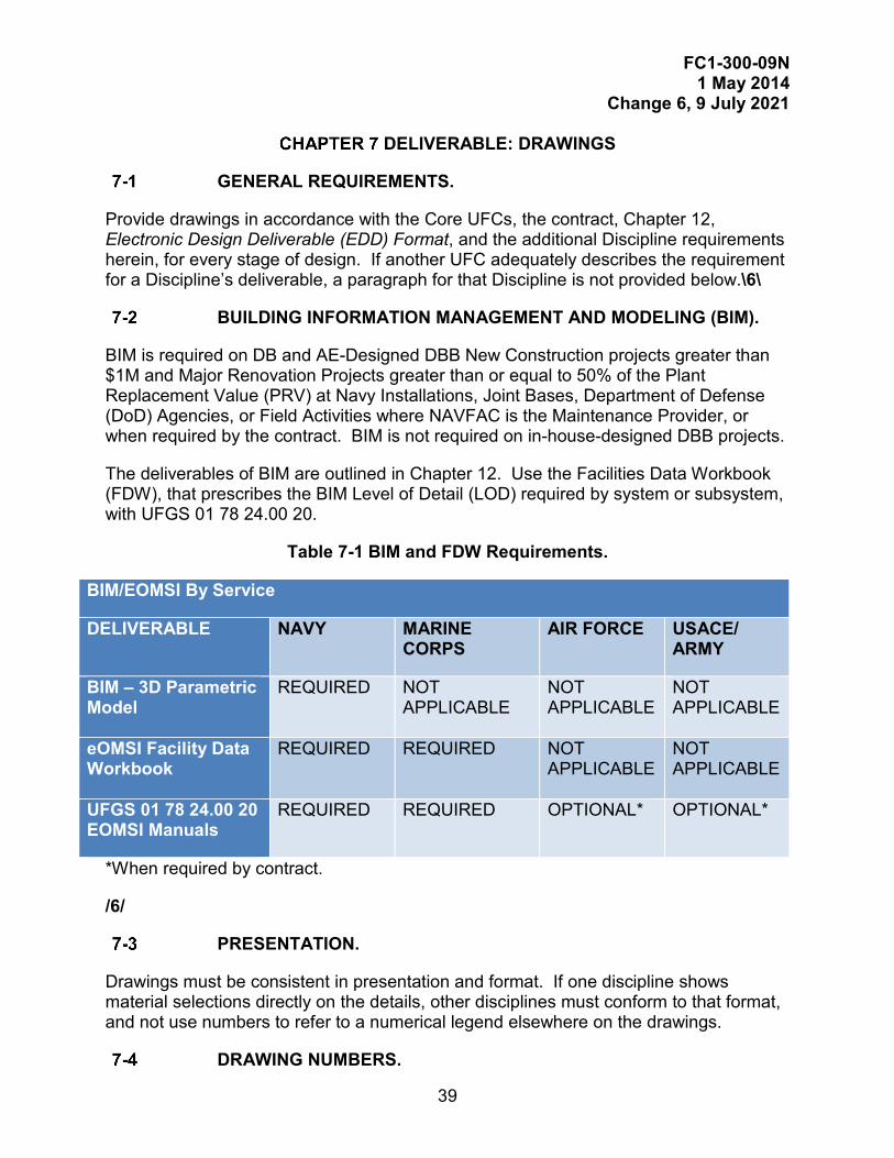
FC1-300-09N 1 May 2014
Change 6, 9 July 2021
39
DELIVERABLE: DRAWINGS
GENERAL REQUIREMENTS.
Provide drawings in accordance with the Core UFCs, the contract, Chapter 12, Electronic Design Deliverable (EDD) Format, and the additional Discipline requirements herein, for every stage of design. If another UFC adequately describes the requirement for a Discipline’s deliverable, a paragraph for that Discipline is not provided below.\6\
BUILDING INFORMATION MANAGEMENT AND MODELING (BIM).
BIM is required on DB and AE-Designed DBB New Construction projects greater than $1M and Major Renovation Projects greater than or equal to 50% of the Plant Replacement Value (PRV) at Navy Installations, Joint Bases, Department of Defense (DoD) Agencies, or Field Activities where NAVFAC is the Maintenance Provider, or when required by the contract. BIM is not required on in-house-designed DBB projects.
The deliverables of BIM are outlined in Chapter 12. Use the Facilities Data Workbook (FDW), that prescribes the BIM Level of Detail (LOD) required by system or subsystem, with UFGS 01 78 24.00 20.
Table 7-1 BIM and FDW Requirements.
BIM/EOMSI By Service
DELIVERABLE NAVY MARINE CORPS
AIR FORCE USACE/ ARMY
BIM – 3D Parametric Model
REQUIRED NOT APPLICABLE
NOT APPLICABLE
NOT APPLICABLE
eOMSI Facility Data Workbook
REQUIRED REQUIRED NOT APPLICABLE
NOT APPLICABLE
UFGS 01 78 24.00 20 EOMSI Manuals
REQUIRED REQUIRED OPTIONAL* OPTIONAL*
*When required by contract.
/6/
PRESENTATION.
Drawings must be consistent in presentation and format. If one discipline shows material selections directly on the details, other disciplines must conform to that format, and not use numbers to refer to a numerical legend elsewhere on the drawings.
DRAWING NUMBERS.
FC1-300-09N 1 May 2014
Change 6, 9 July 2021
40
Request NAVFAC drawing numbers from the Government’s Project Manager or the Design Manager. Provide them with the following information:
1) The amount of numbers required;
2) The eProjects\1\/1/ Work Order Number, and
3) The project title. Request enough numbers (usually 10% more) that additional sheets can be added if necessary.
\1\Only use the Maximo number, in lieu of eProjects Work Order Number, if eProjects is not required for the project./1/
PROPER USE OF NOTES ON DRAWINGS.
• Be consistent with grammar used in notes on drawings. Wherever possible use imperative statements to describe work to be accomplished by Contractor. For example, instead of using “Contractor must provide,” use “provide.” It is understood that the notes are written for the Contractor’s action.
• Do not use “to be” for describing work that will be accomplished by the Contractor. “To be” implies that someone will accomplish the work other than the Contractor, such as the Government or another Contractor. If work is to be accomplished by Government, for example, say “Government will remove storage building prior to start of construction.”
• Do not use “install” for work that is to be accomplished by the Contractor. “Install” means Government or others will furnish equipment or materials and Contractor will install. “Furnish” means Contractor must only furnish; Government or others will install. Use “provide” when the Contractor is to furnish and install equipment and materials.
• Do not use “proposed” for new construction. “Proposed” means future work by others or work not in this contract.
• Do not use “new” for work in the contract. All work shown on the drawings is considered new, unless indicated otherwise. Inconsistent use of “new” throughout the drawings could mean that only some of the work is required.
• Do not use ambiguous statements that cannot be enforced by the inspector during construction. For example: “grade to drain;” “hand excavate carefully;” “provide materials in good condition.”
• Be careful with statements like “remove and replace,” which means to remove old item or material and replace that item or material when work is completed. This statement would be appropriate for work in a pump station where pumps were removed prior to the work and those same pumps replaced after the work is completed. On the contrary, if a portion
FC1-300-09N 1 May 2014
Change 6, 9 July 2021
41
of a concrete walk is cracked and requires replacement, say “remove and provide concrete walk.”
• When referring to requirement for coordination between Contractor and Government agency, for example, use “coordinate utility connection with Contracting Officer;” do not use words such as “Navy,” “ROICC,” or “PWD” for Government Agency.
• Do not indicate “see specifications” \6\ or “per spec” on the drawings. The drawings and the specifications form a complete construction package. If unavoidable, provide reference to the specification section in the project (for example, “…IN ACCORDANCE WITH SPECIFICATION SECTION 09 25 13.13.”)/6/
• Do not use “all” or “any.”
• Do not use words that have multiple meanings, requiring opinions, or judgmental decisions, such as “timely,” “nearly,” “good-condition,” “suitable,” “well-balanced,” “suitable for intended use,” “reasonable,” “approximately,” “reliable,” “proper,” “usable,” “appropriate,” “adequate,” or “qualified.”
• Do not use terms that are not biddable by the Contractor nor enforceable by the Government, such as “recondition,” “as directed,” “equal to,” “as required,” “similar to,” “as necessary,” “as close as possible,” “repair,” “match existing,” or “refurbish.”
• Some terms are only enforceable if quantities are shown on the drawings or included in the specifications, such as “as indicated,” “as shown,” “specified herein,” and “as noted.”
• Be careful when using the word, “typical,” especially if there are exceptions to the detail.
• Use “must” rather than “shall.” \3\
FC1-300-09N 1 May 2014
Change 6, 9 July 2021
42
CODE COMPLIANCE SUMMARY SHEET(S).
The Code Compliance Summary Sheet(s) must be prepared by the QFPE and must be included as “General Sheets” immediately following the title sheets. At a minimum, include the following information:
Building Code Site Plan \4\/4/.
Identify all of the following elements on the Building Code Site Plan:
• Line of encroachment identifying minimum separation distances from adjacent buildings and assumed property lines\4\ of the new construction and of the adjacent structures/4/.
• Building perimeter used for frontage increases. \4\ • Exit discharge paths./4/ • Fire Department vehicle access to building.
• Fire lane width, marking and locations, approach roads and turn radius and location.
• \6\/6/ Intended fire department main entrance to building.
• Location of fire department connections.
• Fire hydrants, post indicator valve or valves and their connected water distribution mains serving building.
• Fire pump room.
• Water storage tanks.
• Hazardous material spill containment tanks.
• Backflow prevention assembly or assemblies serving water-based fire protection systems (if located outside of building).
Building Code Summary.
Identify all of the following elements in the Building Code Summary:
• Classification of occupancy.
• Allowed vs. provided type of construction.
• Basic allowable heights & areas vs. actual heights & areas.
• Allowable vs. provided height or area increases per floor and total.
• Calculations supporting height and area modifications/increases.
• Required vs. provided exterior exposure protection.
• Required vs. provided interior fire rated occupancy separations.
FC1-300-09N 1 May 2014
Change 6, 9 July 2021
43
• Required vs. provided internal fire area separations. \4\ • US Required vs Host Nation Required vs Provided (for OCONUS projects
only)/4/ Life Safety Code® Summary.
Identify all of the following elements in the Life Safety Code® Summary:
• Classification of occupancy of each room, area or compartment (on the drawings or in tabular form);
• Occupant load factor(s) and total calculated load;
• Required vs. provided number of exits;
• Required vs. provided capacity of means of egress;
• Required vs. provided arrangement of means of egress including remoteness of exits, horizontal exits, travel distance, common path of travel, dead-end corridor lengths. When suites are used, indicate type, location, area and arrangement;
• Required vs. provided accessible means of egress;
• Required vs. provided discharge from exits;
• Required vs. provided fire rated separation of exits and exit access;
• Required vs. provided fire rated separation of hazardous areas;
• Flame spread/smoke development ratings of interior finishes;
• Requirements (if any) for smoke control systems based on the specific occupancy chapter and building design considerations;
• Requirements for any special locking arrangements such as delayed-egress locks or access-controlled egress doors. Specify the rooms/area. \4\
• US Required vs Host Nation Required vs Provided (for OCONUS projects only)/4/
Life Safety Plans.
The Life Safety Plans must be prepared by the QFPE and must be included as “General Sheets” immediately following the title sheets and code compliance summary sheets. Scale the floor plans so the entire footprint fits on a single sheet provided that all information is clearly legible and the scale is no smaller than 1/16-inch (1:200). At a minimum, include the following information:
• Location and rating of all fire walls, fire barriers, fire partitions, smoke barriers and smoke partitions (both horizontal and vertical). Barriers requiring fire resistance rated supporting construction must be specifically
FC1-300-09N 1 May 2014
Change 6, 9 July 2021
44
identified for coordination with the structural design partition locations with fire rated partitions and horizontal exits identified.
• Building areas having different occupancy and hazard classifications.
• Room numbers, corresponding occupancy classification and calculated occupant load. Include occupant load of each room, area or compartment (on the drawings or in tabular form). Similar occupancies can be grouped together for occupant load calculations.
• Capacity and number of occupants using each major means of egress component (such as stairs, stair doors, exterior doors, assembly exit doors.)
• Rooms or areas requiring special life safety or fire protection features.
• Location of hazardous materials storage, handling and use that exceed the maximum allowable quantities.
• Egress travel requirements (such as travel distances, common paths of travel, dead-end corridors.)
• Structural fireproofing locations and associated ratings.
• \4\When required, /4/fire extinguisher cabinet and surface-mounted fire extinguisher locations.
• \4\When required, /4/fire extinguisher type/quantity table identifying the total number and type of extinguishers required.
• Location of primary fire alarm/mass notification control panel./3/ CIVIL DRAWINGS.
Cover Sheet, Drawing Index, Vicinity Map, Location Plan, Abbreviations, Legend, and Notes, or First Civil Sheet.
If project is not a Civil Engineering lead, assure that the following items are coordinated with the lead discipline responsible for creating cover sheet:
If General Development Maps (GDM) are used for the Vicinity and Location Maps, edit for the specific project being designed. Ensure street names, main gates, and the Public Works office of the base are identified. Ensure that text is legible at the plotted scale and remove extraneous lines.
The Vicinity Map must identify the Activity and have enough main highway names and street names to allow an out-of-town contractor to locate the work.
The Location Plan must allow the contractor to find the project on the base. This is generally a good place to show laydown areas, haul routes, any construction traffic routing restrictions, and off-site
FC1-300-09N 1 May 2014
Change 6, 9 July 2021
45
benchmark locations. Provide an adequate amount of street names to allow coordination between the Vicinity Map and the construction plans.
In general, it is desirable to show the Vicinity Map and the location Plan on the Cover Sheet along with the project title.
Coordinate with FEAD or ROICC, and Activity for laydown area.
Edit standard details, abbreviations, legends, and general notes for the specific project being designed.
Provide a single Civil legend on one sheet (preferably sheet C-001).
Datum must be securely tied between project datum and local datum.
For projects near tidal waters, show datum sketch indicating project vertical datum and relationship to range of tide and other important datum.
Demolition Plan.
Include the following:
Clearly show what is to be demolished at an appropriate scale. Coordinate/edit the legend to match the demolition plans.
Indicate the beginning and ending points of utility removals and methods of plugging pipes \3\(such as/3/ cap, brick & mortar). Show locations of valves to be used for isolating work.
Show limit of pavement removal and pavement thickness.
Describe the existing items in detail with supplemental descriptions if necessary. Indicate depth of pavements/bases to allow uniform contractor bids.
Provide a sequence of demolition if necessary. Include any known requirement for continuous operation and limited shutdown requirements. These must be identified in the special scheduling paragraphs of the specification.
Do not show any items that are being demolished with the current project on subsequent Civil plan sheets.
Show locations of all erosion and sediment (E&S) control items and add E&S notes. Show erosion control details on drawings or refer to applicable details in the State Erosion and Sediment Control
FC1-300-09N 1 May 2014
Change 6, 9 July 2021
46
Handbook or manual. Verify that the erosion control legend is edited, clear and coordinated with the drawings.
Provide a Tree Protection Detail for existing trees, which are to be preserved during construction. All trees are not amenable to the same barrier fence application. Consult a Registered Landscape Architect or State Certified Arborist. As a minimum, show a 4 foot (1.2 m)- high safety-orange, plastic barrier fence with metal or 4 x 4 inch (101 x 101 mm) wood stakes at 8 foot (2.5 m) on center spacing, continuously located around the tree’s drip-line, unless otherwise directed by a certified arborist. If trees are in a group or cluster, use only one fence to surround the entire cluster.
Site Plan.
Include the following:
Show all new aboveground features including all features required by the BOD \3\(examples:/3/ airfields, railroads, crane rail, small arms ranges) with adequate layout data and existing aboveground features, after demolition has occurred.
Label baselines to be used for project layout as ‘construction baseline’ as opposed to survey baseline.
Provide layout dimensions from the construction baseline, or another readily identified (and easily established) alignment in the field. Include horizontal control point locations and descriptions. Use of coordinates for layout purposes is discouraged, however their use may be considered on a case-by-case basis. Contact Government’s Civil Reviewer for approval of coordinate layout prior to project submittal.
Show areas requiring pavement patching, repairs and new pavement. Provide pavement jointing plans for rigid pavements. Include separate pavement marking plans for airfield projects.
Eliminate extraneous items that may congest the drawing \3\(such as/3/ contours, elevations) and detract from the layout information.
Show locations of any additional E&S control items not already included on the Demolition Plan. Coordinate with E&S notes, details, and legend.
Indicate all trees and plant material to remain.
Provide statement concerning location of soil borings and soil information.
FC1-300-09N 1 May 2014
Change 6, 9 July 2021
47
Water and Sanitary Sewer Plan.
Include the following:
Indicate whether new connections will be made by wet tap (tapping sleeve/valve) or by dry connection. Show nearest valve(s) for system isolation if the latter is the case. Indicate known scheduling issues in the special scheduling paragraphs of the specification.
Indicate surface materials \3\(such as/3/ grass, bituminous, or concrete).
Provide numbers (or letters) for each sanitary structure and water fitting so that plans and profiles are easily coordinated. This labeling system must be clearly distinct from that used for the storm drainage system and preferably distinct from labels used by other utility systems, \3\(such as/3/ electrical).
Provide manhole rim and invert elevations, pipe slopes, pipe diameters and pipe materials. If profiles are provided, indicate slopes on the profile sheets and do not provide on the plan sheets.
For water treatment plants, provide details process and instrumentation diagram (P&ID). \4\
Provide reference to drawings and specifications for cathodic protection of fire protection water storage tanks, piping or water lines, including metallic components of non-metallic lines (for example, PIVs, fire hydrants, change of direction devices, and valves)./4/
Water, Storm, and Sanitary Sewer Profiles.
Show profiles where needed for clarity and to avoid potential conflicts. Discuss profile requirements with Government’s Civil Reviewer.
Indicate structure tops, pipe invert elevations, slopes, lengths, and diameters of all new gravity lines.
Coordinate structure numbers with plan sheets.
Reference the plan sheets where pipes/structures are shown.
Show and label existing and new surface materials, such as concrete pads, curbs, and roads, traversed by the new lines. Accurately show depth of existing pavements.
Show and label all crossing utility lines, both existing and new.
FC1-300-09N 1 May 2014
Change 6, 9 July 2021
48
If depths of existing utilities are unknown, indicate the horizontal location of the utility and indicate the vertical location with a line representing the anticipated range of elevations where the utility will be found in the field. Indicate the method of new utility installation routing above or below conflicts\3\ (such as/3/ concrete encasement or pressure pipe).
Grading and Drainage Plan.
Include the following information:
Provide existing spot elevations and existing contours at intervals to clearly indicate existing drainage patterns.
Provide new spot elevations and new contours when appropriate to clearly indicate new grading and drainage patterns. New spot elevations/contours must be easily distinguished (bolder font) from existing.
Indicate where new grading ties to existing grading (limits) and verify that new work will not block existing adjacent drainage.
Show all benchmarks, temporary benchmarks (tbm’s), other vertical control, and datum notes on this plan.
Show finish floor elevations on grading plans. Do not show finish floor elevations on the architectural or structural plans in order to avoid conflicts. Coordinate adjacent exterior grading with the architectural/structural plans to ensure positive drainage patterns away from the building.
Verify that the slopes indicated on the plans are suitable for the surface material involved\3\(such as/3/ earth slopes, bituminous pavements, and concrete pavements. Consider if these slopes are maintainable for the service life of the facility.
Coordinate with the Landscaping Plans (L sheets) to prevent new plantings from blocking site drainage.
Provide numbers (or letters) for each drainage structure so that plans and profiles are easily coordinated.
Provide erosion and sediment control details.
Site / Utility Details.
Incorporate details as follows:

FC1-300-09N 1 May 2014
Change 6, 9 July 2021
49
If applicable, edit and update standard details provided by the Government’s Civil Reviewer to apply to the particular conditions and requirements of the project.
Details of items shown in the construction standards of the Department of Transportation, or other agencies of the state in which the project will be constructed or other appropriate local/commercial standards are required on the plans.
Pavement Sections.\4\
LANDSCAPE ARCHITECTURAL DRAWINGS.
Landscape Demolition Plan.
Coordinate existing site improvements and existing trees or other plant materials to be demolished with Civil Engineer. If a Civil Engineer is not involved with the project, conform to the requirements listed in Civil Drawings section under Demolition Plan.
Landscape Site Plan.
Coordinate site improvements with Civil Engineer. For projects with detailed Landscape Architectural features provide a Landscape Site Plan. Include the following:
Show all new aboveground features including all features required by the BOD (examples: buildings, existing site features to remain, utilities and other infrastructure improvements, vehicular and pedestrian circulation, parking, hardscape, fire lanes, Indicate hardscape, plazas, courtyards, child play equipment, monuments, memorials, site furniture, fences, walls, trash enclosure, signage, landscape drainage, and other site structures, streetscapes, LID and other bio-retention features, and AT standoff distances) \6\ and unobstructed space /6/ with adequate layout data and existing aboveground features, after demolition has occurred. Provide enlargement plans to delineate appropriate detail in plan view.
Label baselines to be used for detailed Landscape Architectural features layout as ‘construction baseline’ as opposed to survey baseline.
Provide layout dimensions from the construction baseline, or another readily identified (and easily established) alignment in the field. Include horizontal control point locations and descriptions. Use of coordinates for layout purposes is discouraged, however their use may be considered on a case-by-case basis. Contact Government’s Landscape Architectural Reviewer for approval of coordinate layout prior to project submittal.

FC1-300-09N 1 May 2014
Change 6, 9 July 2021
50
Eliminate extraneous items that may congest the drawing (such as contours, elevations) and detract from the layout information.
Landscape Construction Details.
Provide details, sections, and elevations for all site improvements as required for construction.
Landscape Planting Plan.
Show locations of all facilities (such as buildings, parking areas, roads, sidewalks, plazas or patios, existing vegetation to remain, and other surface improvements) and new plantings (such as trees, shrubs, ground cover), LID features, and bio-retention treatments.
Plant Material Schedule and Details.
Include the following:
• Provide a schedule for plant material showing as a minimum: botanical name, common name, quantity of plants, tree trunk caliper, minimum height and spread at time of planting, root condition (for example, balled and burlapped, containerized, and boxed), and a keyed reference to a planting detail.
• Provide separate details for plant types (such as trees, shrubs, ground covers) and other elements (such as root barrier, headers or edging, mulching).
Landscape Irrigation Plan.
When a Landscape Irrigation Plan is required by the Statement of Work, show locations of all facilities (such as buildings, parking areas, roads, sidewalks, plazas and patios, existing vegetation to remain, and other surface improvements). Show all pressure pipe and lateral lines, sprinkler heads, drip tubing and emitters, valves, backflow preventers, water source connections, wells, rain sensors, automatic controllers, rainwater harvesting (and other sustainable design features), and similar items.
Irrigation Equipment Schedule and Details.
When a Landscape Irrigation Plan is required by the Statement of Work, include the following:
• Provide an Irrigation Equipment Schedule showing at a minimum: graphic symbol, description of the item, manufacturer, model number, irrigation nozzle type (for example, full, half, quarter, or bubbler), optimum nozzle pressure (PSI), nozzle radius, and nozzle flow (GPM).

FC1-300-09N 1 May 2014
Change 6, 9 July 2021
51
• Provide separate details for irrigation equipment (such as sprinkler heads, automatic controller, backflow preventer, valves, and other accessories).
• Provide pressure loss calculations.
• Provide water budget watering schedule, and equipment manufacturer’s specifications, operations, and other information./4/
GEOTECHNICAL DRAWINGS.
Include subsurface investigation results on the drawings for record-keeping purposes. As a minimum, the drawings must include the logs as they appear in the Geotechnical Report, a summary table of the laboratory testing, notes concerning the drilling, logs and testing, groundwater observations/conclusions, and any site preparation notes or details, such as undercutting and surcharging.
STRUCTURAL DRAWINGS AND NOTES.
Provide structural drawings that sufficiently detail all structural work. The drawings must contain a set of “Structural Notes” in accordance with UFC 1-200-01, and which provide critical reference information for future building modifications or evaluations. As a minimum, note Design Criteria, Design Standard References, General Construction requirements, and the following:
• Loads: Provide loading information and identify source for all listed loads.
• Foundation Conditions: Fully describe the foundation conditions and list the type of foundation system and method employed to determine allowable soil bearing values. Indicate the minimum allowable bearing capacity for shallow foundations, or the pile or pier capacity in both tension and compression for deep foundations. Indicate passive, active and at rest design pressures, the coefficient of friction and the sub-grade modulus. Indicate if a site specific design spectrum is to be used in the design and give the site class in accordance with the seismic design criteria used.
• Materials: Clearly define the types, grades and properties of materials for each structural element and system.
• Quality Assurance: Provide a summary of the quality assurance requirements.
• Ammunition and Explosive Facilities: Drawings that include a standard approved for Ammunition and Explosive storage facilities must include a note clearly identifying the source, name and date of the standard design.
• Marine Structures: List mooring berthing and deck loads for marine structures, including ship classes \3\(such as/3/ DDG 51, CG 47, CVN) with associated displacements. \3\

FC1-300-09N 1 May 2014
Change 6, 9 July 2021
52
FIRE PROTECTION.
Provide floor plans showing the following information. Scale the floor plan so the entire footprint fits on a single sheet provided that all information is clearly legible and the scale is no smaller than 1:200 or 1/16-inch. Where a building has multiple hazard classifications or areas protected with special fire suppression systems, differentiate each area by border or hatching.
Information pertaining to electronic control/release systems may be shown on the Fire Alarm/Mass Notification Systems drawings specified below.
Fire Sprinkler Systems.
Provide the following information:
• Locations of sprinkler riser room.
• Fire department connections.
• Post indicator valves.
• Isolation control valves.
• Sprinkler branch lines or feed main piping if a specific routing is required, such as single feed to computer room or elevator equipment room and hoistway.
• Location of control panels used for release of pre-action or deluge systems.
• Fire pump and associated equipment. Gaseous Fire Extinguishing Systems.
Provide the following information:
• Outline of area/hazard to be protected.
• Location of storage cylinders and releasing panel.
• System initiating devices (such as manual releases, automatic detection devices).
• Notification appliances.
• Main/reserve transfer switches.
• Control devices such as dampers, shunt trip breakers for computer equipment shutdown, and air conditioning units to be shut down, and electromagnetic door hold-open devices.
AFFF Foam Systems.
Provide the following information:

FC1-300-09N 1 May 2014
Change 6, 9 July 2021
53
• Outline of area/hazard to be protected.
• Locations of all risers, foam proportioning equipment, foam solution discharge devices, manual releases, optical detectors, control panel, pumps, concentrate tanks, test connections.
Fire Suppression Detail Sheets.
Provide fire suppression detail sheets showing the following information:
7-11.4.1 Fire Sprinkler Systems.
• Enlarged plan view of sprinkler riser room showing sprinkler risers, control valves, backflow prevention device and service entrance (supply) manifold drawn to scale.
• Cross-sectional elevations of sprinkler and standpipe risers.
• Enlarged plan view of fire pumps and piping arrangement, jockey pump, and associated controllers and equipment drawn to scale.
• Cross-sectional elevations of fire pump supply and discharge piping arrangement.
• Releasing system riser diagram for pre-action or deluge sprinkler systems. Identify all zones, circuit inputs and circuit outputs necessary for controls, including interconnection with building fire alarm control panel.
7-11.4.2 Gaseous Fire Extinguishing Systems.
• Releasing system riser diagram identifying all zones, circuit inputs and circuit outputs necessary for controls, including interconnection with building fire alarm control panel.
• Elevation view of storage cylinders and manifold.
• Isometric detail drawing of agent distribution piping including storage cylinder manifold and discharge nozzles.
• Sequence of Operation Matrix. See NFPA 72 for sample. 7-11.4.3 AFFF Foam Systems.
• Complete layout of the pump room showing location of fire and foam pumps, concentrate storage tanks, and all associated equipment drawn to scale.
• AFFF riser detail showing foam proportion method, test line connection, and all associated valves.
• Details of AFFF discharge devices (such as foam makers, nozzles).
FC1-300-09N 1 May 2014
Change 6, 9 July 2021
54
• Releasing system riser diagram. Identify all zones, circuit inputs and circuit outputs necessary for controls, including interconnection with building fire alarm control panel.
• Isometric detail of foam concentrate delivery system showing concentrate piping, proportioning equipment, concentrate pumps and concentrate storage tank, flow control valves, foam inductors, foam concentrate tank, and all associated valves.
• Sequence of Operation Matrix. See NFPA 72 for sample. Fire Alarm/Mass Notification System Plans.
Provide floor plans identifying location of field installed components and interconnected devices. Plans may identify fire suppression control/release system information identified above. At a minimum, identify the location of the following information:
• Control panel(s).
• \4\Notification appliance circuit/4/ extender panels.
• Radio transmitter or master box.
• Line and low voltage surge arrestors.
• All initiating devices (including duct smoke detectors). In lieu of locating devices on the plans, and as authorized by the DFPE, provide the following information on the plans:
o Ambient sound pressure levels and audible design sound pressure levels, o Area boarders or other means to identify differing distinguishable spaces (ADS) o Area borders to indicate the type of detection system, initiating devices, notification appliances and releasing service o Area borders for detection and notification zones o Rooms and spaces that will have visible notification and those where visible notification will not be provided o Rooms and spaces that will have initiating devices and the design performance requirements for those devices /4/
• \4\/4/ • Supplemental equipment interfaced with the fire alarm system such as
voice evacuation panels, electromagnetic door holders, delayed-egress or access-controlled doors, elevator system components.
FC1-300-09N 1 May 2014
Change 6, 9 July 2021
55
• Supplemental fire suppression equipment control panels such as fire/foam pump controllers, Fire suppression control/release panels.
Fire Alarm/Mass Notification System Detail Sheets.
Detail sheets may identify fire suppression control/release system information identified above.
7-11.6.1 Riser Diagram.
Provide a riser diagram showing hierarchy, arrangement and zoning of the system. Identify all typical circuits, interconnections and interlocks necessary for associated controls. Do not identify every field device individually, such as smoke and heat detectors. Identify required line and low voltage surge arrestors. Interface with security systems for required delayed-egress or access-controlled doors. Identify interface with fire suppression control/release panels.
7-11.6.2 Sequence of Operation Matrix.
\4\/4/See NFPA 72 for sample. /3/
DRAWINGS PREPARED FOR OTHER GOVERNMENT ORGANIZATIONS.
Approval of drawings for projects of other Government organizations or approval of modifications or revisions of drawings prepared by such organizations is required as follows:
• Indicate approval by other Government departments or agencies by appropriate signature in the supplemental locations provided on the NAVFAC Title Block (\1\in accordance/1/ with Chapter 12).
• When NAVFAC drawings are prepared for construction projects for other Government departments or agencies, submit fully developed concept designs to the appropriate departments or agencies for formal approval.
• For drawings prepared under the direction of NAVFAC, the other Government organization provides approval solely for functional and operational sufficiency.
• When definitive, standard, or project drawings of other Government departments or agencies are used by NAVFAC for design of projects for those departments or agencies, make modifications or revisions to such drawings only with the approval of the department or agency concerned, unless NAVFAC has been authorized otherwise.

FC1-300-09N 1 May 2014
Change 6, 9 July 2021
56
This Page Intentionally Left Blank.
FC1-300-09N 1 May 2014
Change 6, 9 July 2021
57
DELIVERABLE: SPECIFICATIONS
GENERAL REQUIREMENTS.
Provide specifications in accordance with UFC 1-200-01, the Core UFCs, UFC 1-300-02, and Chapter 12. Provide specifications that are as brief as possible, definitive, and free of ambiguities and omissions that may result in controversy and contractor claims for additional compensation.
GUIDE SPECIFICATIONS.
Specifications offer criteria for materials, equipment, and test methods. Guide specifications are documents that describe products and materials and the work necessary to incorporate them into a construction project. A guide specification facilitates the preparation of project specifications by standardizing products and processes, and their order of presentation. DoD uses the Unified Facilities Guide Specifications (UFGS) database, provided on the Whole Building Design Guide website (http://www.wbdg.org), which is updated quarterly. Edit guide specifications to specific project requirements for incorporation into the contract documents. Guide specification and project specification sections describe the following in detail:
• Product or system to be provided,
• Salient design features or performance requirements of the product or system,
• Quality of that product or system and methods used to ensure the quality, including on-site and off-site testing,
• Method to be used to incorporate the product or system into the project, and
• Other features and functions necessary. Guide specification section numbers, up to 10 digits, in CSI MasterFormat 2004, are grouped in pairs. Each of these groupings is referred to as a “level,” from one to five. Refer to the CSI MasterFormat website at http://www.csinet.org/mfnumber for further explanation.
Unified Facilities Guide Specifications (UFGS).
Use Unified Facilities Guide Specifications (UFGS) for all projects, including Design-Build. UFGS are available at the Whole Building Design Guide website at http://dod.wbdg.org/. Tailor and modify the UFGS as necessary to suit the work required by the specific project, including editing for metric or inch-pound. In addition, modify and edit to reflect the latest proven technology, materials, and methods, for the project.
FC1-300-09N 1 May 2014
Change 6, 9 July 2021
58
There is only one current version of a guide specification at any time. The guide specification with the latest revision date and change number automatically cancels specifications of the same number with a previous date and change number.
Regional Guide Specifications.
Some Supported Commands have modified some of the UFGS for their region; these are referred to as Regional Guide Specifications. Use Regional Guide Specifications when sections are available by the Region and Activity for the project location, and as required by the contract. Regional specifications are located on the Whole Building Design Guide website at\5\ https://www.wbdg.org/ffc/navy-navfac/regional-specifications /5/ and where indicated in the contract.
Regional specifications are limited in number and scope to selected subjects particular to a location and contain a majority of local requirements. Regional specifications are used in the same way as the UFGS except that they are used only in the area of the specific facility engineering command jurisdiction. Regional specifications are numbered the same as the UFGS that has been used as a basis for the regional specification, with the exception of a regional designation at the fifth level for specifications in CSI MasterFormat\6\ /6/; for example, in UFGS Section number, 01 13 30.00 22, “22” indicates the region. Assigned regional designations can be found with the Regional specifications at \5\https://www.wbdg.org/ffc/navy-navfac/regional-specifications./5/
Other Guide Specifications.
Other guide specifications are only allowed as a basis for information when not available in the UFGS. These developed specifications must be provided in UFGS format and modified to meet requirements of UFC 1-300-02. Do not use NASA UFGS specification sections (ends with “40” at the fifth level).
UFGS Selection Order of Precedence.
Unless specified otherwise in the contract, the order of precedence for selecting which UFGS to start from, for CONUS jobs that require the use of the UFGS, is as follows:
1) Regional Guide Specifications (for the project location and where sections are \4\published on WBDG/4/).
2) UFGS, Navy only (UFGS with a “20” at the fifth level in CSI MasterFormat).
3) UFGS (unified, no designator at the fifth level).
4) Other DoD UFGS (Army UFGS with .00 10 designation and modified for Navy job)
5) Other Guide Specifications.\6\(no NASA UFGS)/6/
FC1-300-09N 1 May 2014
Change 6, 9 July 2021
59
Design-Build Performance Technical Specifications.
Develop Performance Technical Specification (PTS) sections in accordance with requirements of Chapter 11.
PROJECT PREPARATION POLICIES AND GUIDANCE.
Prepare specifications in Format and Styles required by UFC 1-300-02.
UFGS Version Date.
Download, use, and edit the most current UFGS database available from the Whole Building Design Guide website, http://dod.wbdg.org/. Unless otherwise specified by the contract, the version that is current at the official start of the Pre-Final design phase must be used, and continue to be used, through Final design. Coordinate the version of the UFGS database used with the Government’s project manager, and report this date to them.
Editing of Specifications for Project.
\1\Modify and edit the guide specification to fit the project and to meet UFC requirements. Follow the Notes to the Designer to make selections in the UFGS. Use language and format in accordance with UFC 1-300-02. Delete portions of the guide specification not included in the project design and scope./1/
Use guide specifications only as source documents, and do not reference them in project specifications. Do not combine work covered by various UFGSs into one section unless the project is small and work is of a minor nature, and the Government Project Manager concurs.
8-3.2.1 \1\Geotechnical and Civil Specifications.
Do not edit outside of the guide specification’s bracketed selections for Geotechnical and Civil UFGS sections in \6\ Divisions 31 and 32, /6/ without prior approval of the Government project manager./1/
Standard Plates, Sketches, and Details.
Provide plates, sketches, boring logs, and details on the drawings, and not in the specifications.
Unrestricted Bidding.
Provide only the actual minimum needs of the Government in the specifications, and describe the salient characteristics of materials and installation so as to encourage maximum competition in bidding. Eliminate, insofar as possible, any restrictive features that might limit acceptable offers to one supplier's product, or to the products of a relatively few suppliers, and as required further by UFC 1-300-02. Do not list

FC1-300-09N 1 May 2014
Change 6, 9 July 2021
60
manufacturers unless Contracting Officer approval is received in accordance with NFAS 6.304. Master UFGSs that list manufacturers must have a class justification on file.
Contract Parties.
Do not designate part of the work to be performed by a particular subcontractor (\3\such as/3/ the plumbing contractor) in constructing the project, except for some specific instances. The Government recognizes only one Contractor (the prime or general contractor), and it is the Contractor's responsibility to divide up the work.\6\
Facilities Electronic Operation and Maintenance Systems Information (eOMSI).
EOMSI (UFGS 01 78 24.00 20) is required on New Construction projects greater than or equal to $1Million, and Major Renovation Projects greater than or equal to 50 percent of the Plant Replacement Value (PRV), at Navy and Marine Corps Installations Joint Bases, Department of Defense (DoD) Agencies, or Field Activities, where NAVFAC is the maintenance provider of the facility. Also use UFGS 01 78 24.00 20 for projects using BIM or when required by the contract. Use both UFGS 01 78 23 and UFGS 01 78 24.00 20.
The eOMSI Facility Data Workbook (FDW) is required for facilities operated and maintained by NAVFAC and Marine Corps. For BIM projects, use the FDW to prescribe the Level of Detail/6/
COORDINATION OF SPECIFICATIONS AND DRAWINGS.
FAR 52-236-21, Specifications and Drawings for Construction states: "Where 'as shown’, 'as indicated’, 'as detailed’, or words of similar import are used, the reference is made to the drawings accompanying this contract unless stated otherwise."
DBB Contract Order of Precedence.
For Design-Bid-Build contracts, the Contract Order of Precedence is defined in FAR 52-236-21. In general, treat anything mentioned in the specifications but not shown on the drawings or shown on the drawings but not included in the specifications, as if shown or mentioned in both. In the case of discrepancies between the drawings and specifications, the specifications take precedence.
DB Contract Order of Precedence.
For Design-Build, the Order of Precedence for RFP contracts is described in NFAS Clause 5252.236-9312.
Coordination.
FC1-300-09N 1 May 2014
Change 6, 9 July 2021
61
Coordinate the drawings and the specifications to ensure that all items depicted in the drawings are covered by an appropriate specification section and that all specification sections relate to items in the drawings.
USE OF UFGS AND SPECSINTACT.
Edit and provide UFGS sections in accordance with UFC 1-300-02, using SpecsIntact software and UFGS format. SpecsIntact is the word processing software used to edit the UFGS database. SpecsIntact software is available for download, free of charge, at the SpecsIntact web site (http://specsintact.ksc.nasa.gov/).
SPECIFICATIONS PACKAGE ORGANIZING STRUCTURE.
Coversheet.
Include an overall cover sheet, for signature, with project specification package. Type in the name and title of the principle DOR, who must sign in the “Submitted By” location. The coversheet for electronic signature is available on the Whole Building Design Guide at \5\https://www.wbdg.org/ffc/navy-navfac/project-information-form-specifications-cover-sheet./5/
\1\Use the eProjects Work Order Number; only use the Maximo number on coversheet and other project documents if eProjects is not required for the project./1/
Contract Documents.
The DOR prepares and provides the following documents to the Government’s Project Manager for the Contract Specialist. The Contract Specialist consolidates bidding and contract requirements, along with the drawings and specifications, into a single solicitation package.
8-6.2.1 Document 00 22 13.00 20.
Provide UFGS Document 00 22 13.00 20, Supplementary Instructions to Offerors separately and as an attachment to the Project Information Form (PIF). Do not combine with the specifications package or include in the Table of Contents. Convert the final UFGS document to Word or PDF, and provide in that format for the Contract Specialist’s use.
The Contract Specialist includes this document information, along with the information from the PIF, in the contract clauses portion of the solicitation. A sample of UFGS Document 00 22 13.00 20 is provided in Appendix C.
8-6.2.2 Project Synopsis.
The scope in the project synopsis is taken from the Description of Work located in UFGS Section 01 11 00. This description of work must be concise, and summarize the location, facilities, and type of work involved. A sample synopsis is provided in

FC1-300-09N 1 May 2014
Change 6, 9 July 2021
62
Appendix C. Provide the scope of work for the Synopsis at Pre-Final and Final in accordance with contract requirements.
Format.
Provide specifications in UFGS format in accordance with UFC 1-300-02. Print job headers with the job title, exactly as it appears on the drawings, justified to the left, and with the eProjects Work Order Number \1\/1/ justified to the right. For Prefinal submittals, follow the job title with “(Prefinal).”
General Requirements (Division 00 and 01) Specifications.
Edit the UFGS Division 00 and 01, General Requirements Divisions to describe the general project requirements of the project. Provide any additional requirements, of a general nature, rather than of a technical nature, in General Requirements.
The UFGS sections in Table 8-1 are typically used in a Design-Bid-Build project Use other Division One sections as required, depending on the scope of the project, or as required by the Contract. Omit UFGS Document 00 22 13.00 20 from the Table of Contents, and provide separately in the submittal package with the PIF. Provide UFGS Document 00 01 15 as part of the specifications package, or separately, in accordance with Contract requirements.

FC1-300-09N 1 May 2014
Change 6, 9 July 2021
63
Table 8-1 Commonly Used DBB UFGS Division 00 and 01 Sections
UFGS Number TITLE
00 01 15 LIST OF DRAWINGS (sometimes not provided in TOC) 01 11 00 SUMMARY OF WORK 01 14 00 WORK RESTRICTIONS 01 20 00.00 20 PRICE AND PAYMENT PROCEDURES 01 30 00 ADMINISTRATIVE REQUIREMENTS 01 32 17.00 20 \1\COST-LOADED/1/ NETWORK ANALYSIS SCHEDULES (NAS) 01 33 00 SUBMITTAL PROCEDURES (attach Submittal Register) 01 33 29 \1\SUSTAINABILITY REQUIREMENTS AND REPORTING/1/ 01 35 26 GOVERNMENTAL SAFETY REQUIREMENTS \1\01 42 00 SOURCES FOR REFERENCE PUBLICATION/1/ 01 45 00.00 20 QUALITY CONTROL 01 50 00 TEMPORARY CONSTRUCTION FACILITIES AND CONTROLS 01 57 19 TEMPORARY ENVIRONMENTAL CONTROLS 01 57 19.01 20 SUPPLEMENTARY TEMPORARY ENVIRONMENTAL CONTROLS 01 58 00 PROJECT IDENTIFICATION (attach Project Signboards) \1\/1/ 01 78 00 CLOSEOUT SUBMITTALS 01 78 23 OPERATION AND MAINTENANCE DATA 01 78 24.00 20 FACILITY ELECTRONIC OPERATION MAINTENANCE AND
SUPPORT INFORMATION (eOMSI) (attach Facility Data Workbook)
Design-Build RFP.
For Part 2, “General Requirements,” of the six part Design-Build RFP, use the UFGS sections provided in Part Two of the Whole Building Design Guide, NAVFAC Design-Build master, as appropriate, available at the following location: http://www.wbdg.org/ndbm. Table 8-2 shows commonly used Design-Build RFP Part Two UFGS section.
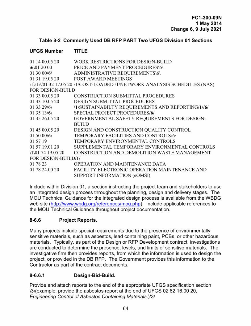
FC1-300-09N 1 May 2014
Change 6, 9 July 2021
64
Table 8-2 Commonly Used DB RFP PART Two UFGS Division 01 Sections
UFGS Number TITLE
01 14 00.05 20 WORK RESTRICTIONS FOR DESIGN-BUILD \6\01 20 00 PRICE AND PAYMENT PROCEDURES\6\ 01 30 00/6/ ADMINISTRATIVE REQUIREMENTS\6\ 01 31 19.05 20 POST AWARD MEETINGS \1\\1\\/01 32 17.05 20 /1/COST-LOADED /1/NETWORK ANALYSIS SCHEDULES (NAS) FOR DESIGN-BUILD 01 33 00.05 20 CONSTRUCTION SUBMITTAL PROCEDURES 01 33 10.05 20 DESIGN SUBMITTAL PROCEDURES 01 33 29\6\ \1\SUSTAINABILTY REQUIREMENTS AND REPORTING/1//6/ 01 35 13\6\ SPECIAL PROJECT PROCEDURES/6/ 01 35 26.05 20 GOVERNMENTAL SAFETY REQUIREMENTS FOR DESIGN- BUILD 01 45 00.05 20 DESIGN AND CONSTRUCTION QUALITY CONTROL 01 50 00\6\ TEMPORARY FACILITIES AND CONTROLS/6/ 01 57 19 TEMPORARY ENVIRONMENTAL CONTROLS 01 57 19.01 20 SUPPLEMENTAL TEMPORARY ENVIRONMENTAL CONTROLS \1\01 74 19.05 20 CONSTRUCTION AND DEMOLITION WASTE MANAGEMENT FOR DESIGN-BUILD/1/ 01 78 23 OPERATION AND MAINTENANCE DATA 01 78 24.00 20 FACILITY ELECTRONIC OPERATION MAINTENANCE AND
SUPPORT INFORMATION (eOMSI) Include within Division 01, a section instructing the project team and stakeholders to use an integrated design process throughout the planning, design and delivery stages. The MOU Technical Guidance for the integrated design process is available from the WBDG web site (http://www.wbdg.org/references/mou.php). Include applicable references to the MOU Technical Guidance throughout project documentation.
Project Reports.
Many projects include special requirements due to the presence of environmentally sensitive materials, such as asbestos, lead containing paint, PCBs, or other hazardous materials. Typically, as part of the Design or RFP Development contract, investigations are conducted to determine the presence, levels, and limits of sensitive materials. The investigative firm then provides reports, from which the information is used to design the project, or provided in the DB RFP. The Government provides this information to the Contractor as part of the contract documents.
8-6.6.1 Design-Bid-Build.
Provide and attach reports to the end of the appropriate UFGS specification section \3\(example: provide the asbestos report at the end of UFGS 02 82 16.00 20, Engineering Control of Asbestos Containing Materials.)/3/
FC1-300-09N 1 May 2014
Change 6, 9 July 2021
65
8-6.6.2 Design-Build.
For DB, provide project reports in Part 6 of the RFP.
Combining Multiple Projects into One Bid Package.
Occasionally, several projects, that have been independently prepared, or need to be easily separated, will be combined into one solicitation package. One solution is to combine the packages into at least three Parts.
8-6.7.1 Design-Bid-Build Parts.
In Part A, provide one General Requirements (Division 01) specification for the entire package. This Division 01 must be edited and accurate for all of the combined projects. The header in Part A must list the titles of each project, justified to the left, and the corresponding eProjects Work Order Number \1\/1/ number, for each project, justified to the right. Example is provided in Figure 8-1.
Part B consists of the technical specifications (Divisions 02-49) for the first project, and Part C consists of the technical specifications for the second project. Add additional parts depending on the number of projects being combined. Provide a Divider, a Table of Contents, and the technical specification sections. The header in each part must contain only the title of that Project, and the corresponding eProjects Work Order Number, for that project. An example is provided in Figure 8-1.
8-6.7.2 Design-Build Parts.
Part A consists of the General Requirements Division (Division 01), Part B consists of the RFP (Parts 3-6) for the first project, and Part C consists of the RFP for the second project. Add additional parts depending on the number of projects being combined. Provide a Divider, a Table of Contents, and the RFP sections (Parts 3-6). The header in each part must contain only the title of that Project, and the corresponding eProjects Work Order Number, for that project.
For RFP’s in which Parts are shared, such as Part 2, Part 4, and Part 5, projects may be combined by simply using a Part 3 for each project, distinguished by the cover page and title, and inserted in Part 3; and a Part 6 for each project, distinguished by the title, and inserted in Part 6. In this case, parts A, B, and C dividers may not be required. Reflect the layout in the overall Table of Contents.
8-6.7.3 DB and DBB Hybrid.
For contracts where a Design-Build RFP is combined with a Design-Bid-Build project, provide one project, complete, in Part A, and the other project, complete, in Part B; do not combine the General Requirements (Division 01) of these two different types of projects. An example is provided in Figure 8-2.
8-6.7.4 Coversheet.

FC1-300-09N 1 May 2014
Change 6, 9 July 2021
66
Provide one overall coversheet for signature. The coversheet must contain all of the eProjects Work Order Numbers. Contact the Government for which Work Order Number to use first as the primary. Also include all project titles, and if different Designers of Record prepared the RFP or specification, the information of each DOR firm or agency. Be careful not to change the location of the electronic signature portlets when adding information to the coversheet.
8-6.7.5 List of Drawings.
Provide UFGS 00 01 15, List of Drawings, listing all of the drawings in the entire package. Group drawing lists by Project.
8-6.7.6 Table of Contents.
Provide a single, overall Table of Contents, listing each Part and the sections or documents in each Part. Note that SpecsIntact uses Courier New (10 pt) as the default font. Use this font to generate the Table of Contents and any other documents in Word. A sample Table of Contents is provided in Figure 8-1 and Figure 8-2.
8-6.7.7 Submittal Registers.
Provide submittal registers for each Part at the end of UFGS 01 33 00, Submittal Procedures (for DBB) or UFGS 01 33 00.05 20, Construction Submittal Procedures (for DB). Separate the submittal register for each part with a Divider; for example, bookmark “Part A: Submittal Register” (for Division 01 only), “Part B: Submittal Register,” and “Part C Submittal Register,” within the PDF package.
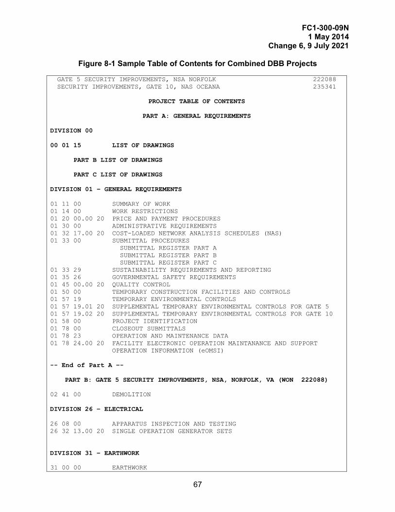
FC1-300-09N 1 May 2014
Change 6, 9 July 2021
67
Figure 8-1 Sample Table of Contents for Combined DBB Projects
GATE 5 SECURITY IMPROVEMENTS, NSA NORFOLK 222088 SECURITY IMPROVEMENTS, GATE 10, NAS OCEANA 235341
PROJECT TABLE OF CONTENTS
PART A: GENERAL REQUIREMENTS
DIVISION 00 00 01 15 LIST OF DRAWINGS
PART B LIST OF DRAWINGS PART C LIST OF DRAWINGS
DIVISION 01 – GENERAL REQUIREMENTS 01 11 00 SUMMARY OF WORK 01 14 00 WORK RESTRICTIONS 01 20 00.00 20 PRICE AND PAYMENT PROCEDURES 01 30 00 ADMINISTRATIVE REQUIREMENTS 01 32 17.00 20 COST-LOADED NETWORK ANALYSIS SCHEDULES (NAS) 01 33 00 SUBMITTAL PROCEDURES SUBMITTAL REGISTER PART A SUBMITTAL REGISTER PART B SUBMITTAL REGISTER PART C 01 33 29 SUSTAINABILITY REQUIREMENTS AND REPORTING 01 35 26 GOVERNMENTAL SAFETY REQUIREMENTS 01 45 00.00 20 QUALITY CONTROL 01 50 00 TEMPORARY CONSTRUCTION FACILITIES AND CONTROLS 01 57 19 TEMPORARY ENVIRONMENTAL CONTROLS 01 57 19.01 20 SUPPLEMENTAL TEMPORARY ENVIRONMENTAL CONTROLS FOR GATE 5 01 57 19.02 20 SUPPLEMENTAL TEMPORARY ENVIRONMENTAL CONTROLS FOR GATE 10 01 58 00 PROJECT IDENTIFICATION 01 78 00 CLOSEOUT SUBMITTALS 01 78 23 OPERATION AND MAINTENANCE DATA 01 78 24.00 20 FACILITY ELECTRONIC OPERATION MAINTANANCE AND SUPPORT OPERATION INFORMATION (eOMSI) -- End of Part A –-
PART B: GATE 5 SECURITY IMPROVEMENTS, NSA, NORFOLK, VA (WON 222088) 02 41 00 DEMOLITION DIVISION 26 – ELECTRICAL 26 08 00 APPARATUS INSPECTION AND TESTING 26 32 13.00 20 SINGLE OPERATION GENERATOR SETS DIVISION 31 – EARTHWORK 31 00 00 EARTHWORK
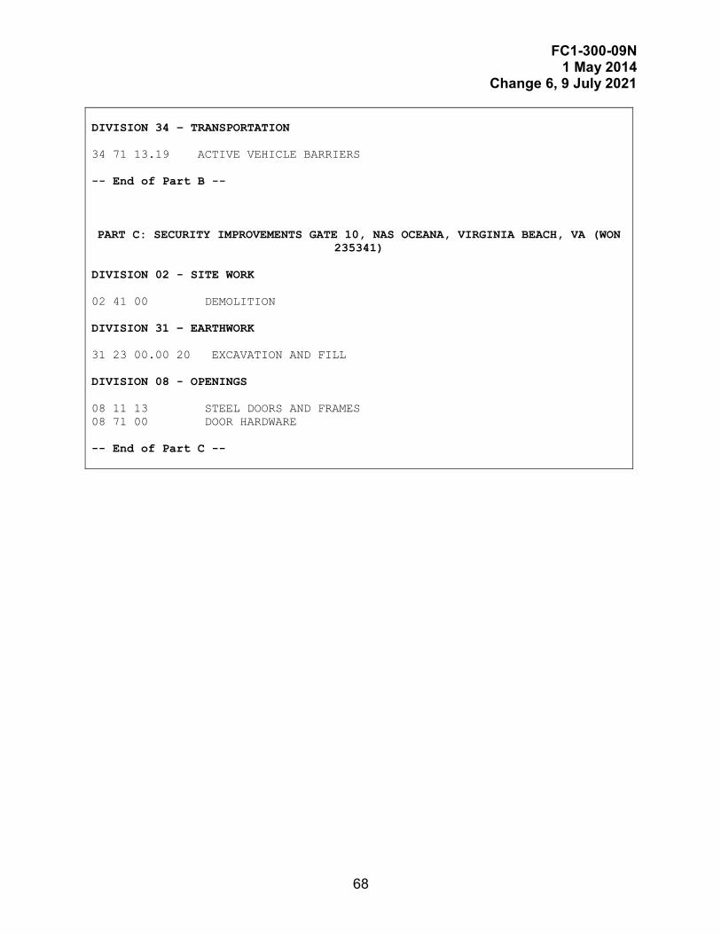
FC1-300-09N 1 May 2014
Change 6, 9 July 2021
68
DIVISION 34 – TRANSPORTATION 34 71 13.19 ACTIVE VEHICLE BARRIERS -- End of Part B --
PART C: SECURITY IMPROVEMENTS GATE 10, NAS OCEANA, VIRGINIA BEACH, VA (WON 235341)
DIVISION 02 - SITE WORK 02 41 00 DEMOLITION DIVISION 31 – EARTHWORK 31 23 00.00 20 EXCAVATION AND FILL DIVISION 08 - OPENINGS 08 11 13 STEEL DOORS AND FRAMES 08 71 00 DOOR HARDWARE -- End of Part C --
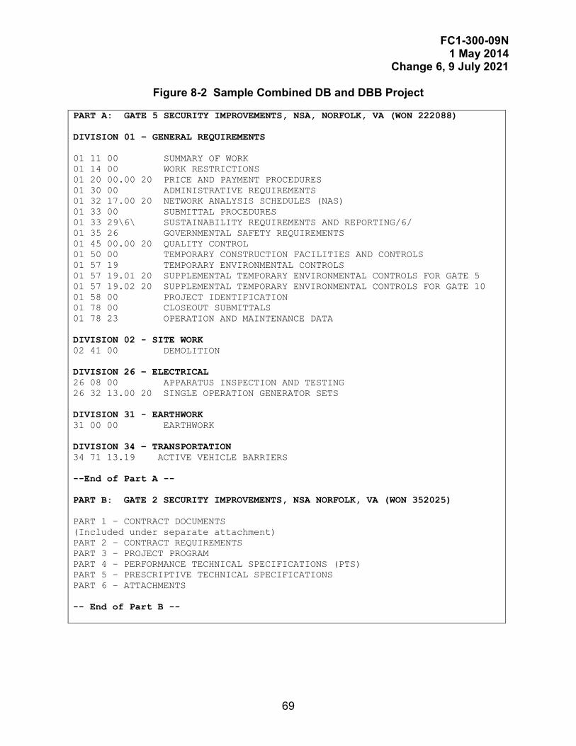
FC1-300-09N 1 May 2014
Change 6, 9 July 2021
69
Figure 8-2 Sample Combined DB and DBB Project
PART A: GATE 5 SECURITY IMPROVEMENTS, NSA, NORFOLK, VA (WON 222088) DIVISION 01 – GENERAL REQUIREMENTS 01 11 00 SUMMARY OF WORK 01 14 00 WORK RESTRICTIONS 01 20 00.00 20 PRICE AND PAYMENT PROCEDURES 01 30 00 ADMINISTRATIVE REQUIREMENTS 01 32 17.00 20 NETWORK ANALYSIS SCHEDULES (NAS) 01 33 00 SUBMITTAL PROCEDURES 01 33 29\6\ SUSTAINABILITY REQUIREMENTS AND REPORTING/6/ 01 35 26 GOVERNMENTAL SAFETY REQUIREMENTS 01 45 00.00 20 QUALITY CONTROL 01 50 00 TEMPORARY CONSTRUCTION FACILITIES AND CONTROLS 01 57 19 TEMPORARY ENVIRONMENTAL CONTROLS 01 57 19.01 20 SUPPLEMENTAL TEMPORARY ENVIRONMENTAL CONTROLS FOR GATE 5 01 57 19.02 20 SUPPLEMENTAL TEMPORARY ENVIRONMENTAL CONTROLS FOR GATE 10 01 58 00 PROJECT IDENTIFICATION 01 78 00 CLOSEOUT SUBMITTALS 01 78 23 OPERATION AND MAINTENANCE DATA DIVISION 02 - SITE WORK 02 41 00 DEMOLITION DIVISION 26 – ELECTRICAL 26 08 00 APPARATUS INSPECTION AND TESTING 26 32 13.00 20 SINGLE OPERATION GENERATOR SETS DIVISION 31 - EARTHWORK 31 00 00 EARTHWORK DIVISION 34 – TRANSPORTATION 34 71 13.19 ACTIVE VEHICLE BARRIERS --End of Part A -- PART B: GATE 2 SECURITY IMPROVEMENTS, NSA NORFOLK, VA (WON 352025) PART 1 – CONTRACT DOCUMENTS (Included under separate attachment) PART 2 – CONTRACT REQUIREMENTS PART 3 – PROJECT PROGRAM PART 4 – PERFORMANCE TECHNICAL SPECIFICATIONS (PTS) PART 5 – PRESCRIPTIVE TECHNICAL SPECIFICATIONS PART 6 – ATTACHMENTS
-- End of Part B --

FC1-300-09N 1 May 2014
Change 6, 9 July 2021
70
This Page Intentionally Left Blank.

FC1-300-09N 1 May 2014
Change 6, 9 July 2021
71
DELIVERABLE: \6\COST ESTIMATES, RISK ANALYSIS, CONSTRUCTION SCHEDULES, AND VALUE ENGINEERING/6/
GENERAL REQUIREMENTS.
\4\Provide cost estimates for each project phase and at each submittal stage in accordance with \5\ the applicable provisions of UFC 3-701-01, UFC 3-730-01, and UFC 3-740-05 unless specifically indicated otherwise in this chapter or in the contract documents/1//5/.
\6\Provide Cost and Schedule Risk Analysis (CSRA) when required by the scope of services and in support of the cost estimate. Provide construction schedules in support of the cost estimate. Provide Value Engineering (VE) services when required by the scope of services./6/
ESTIMATE CLASS STANDARDS AND REQUIREMENTS.
Estimate \5\classifications based on the maturity of the project definition deliverables/5/ provided in Appendix D, Table D-1.
Table 9-1 indicates the appropriate AACE RP 56R-08 estimate class with the commensurate project phase.
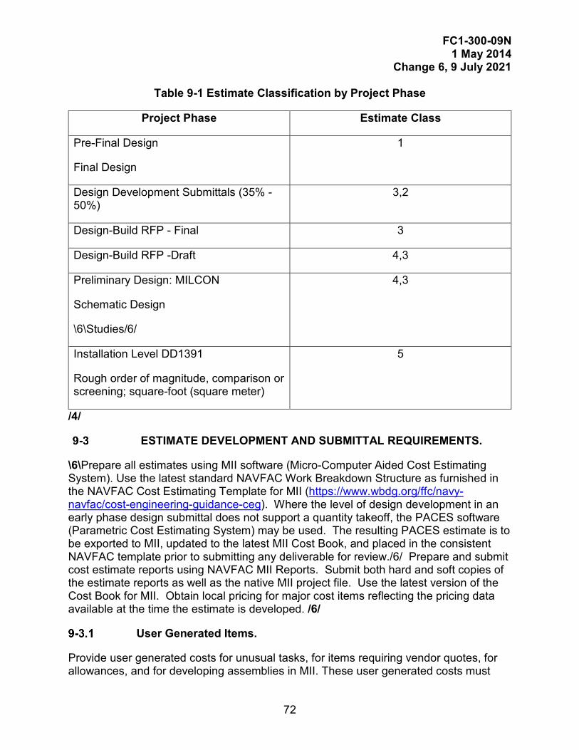
FC1-300-09N 1 May 2014
Change 6, 9 July 2021
72
Table 9-1 Estimate Classification by Project Phase
Project Phase Estimate Class
Pre-Final Design
Final Design
1
Design Development Submittals (35% - 50%)
3,2
Design-Build RFP - Final 3
Design-Build RFP -Draft 4,3
Preliminary Design: MILCON
Schematic Design
\6\Studies/6/
4,3
Installation Level DD1391
Rough order of magnitude, comparison or screening; square-foot (square meter)
5
/4/
ESTIMATE DEVELOPMENT AND SUBMITTAL REQUIREMENTS.
\6\Prepare all estimates using MII software (Micro-Computer Aided Cost Estimating System). Use the latest standard NAVFAC Work Breakdown Structure as furnished in the NAVFAC Cost Estimating Template for MII (https://www.wbdg.org/ffc/navy-navfac/cost-engineering-guidance-ceg). Where the level of design development in an early phase design submittal does not support a quantity takeoff, the PACES software (Parametric Cost Estimating System) may be used. The resulting PACES estimate is to be exported to MII, updated to the latest MII Cost Book, and placed in the consistent NAVFAC template prior to submitting any deliverable for review./6/ Prepare and submit cost estimate reports using NAVFAC MII Reports. Submit both hard and soft copies of the estimate reports as well as the native MII project file. Use the latest version of the Cost Book for MII. Obtain local pricing for major cost items reflecting the pricing data available at the time the estimate is developed. /6/
User Generated Items.
Provide user generated costs for unusual tasks, for items requiring vendor quotes, for allowances, and for developing assemblies in MII. These user generated costs must
FC1-300-09N 1 May 2014
Change 6, 9 July 2021
73
provide sufficient explanation in the item note field for the reader to understand how the item was developed and what it includes.
Level of Detail
The detail for each cost estimate must be commensurate with the level of the development of the project definition deliverables provided for each submittal. \6\ Estimates may be started using PACES. /6/Whether the detail quantity items are developed from a quantity takeoff or from a PACES estimate, the details are to appear at the appropriate locations and levels in the work breakdown structure. See Table 9-2.
Each of the folders in the NAVFAC template includes notes indicating the unit of measure (UOM) to be used for that folder in accordance with UNIFORMAT II. Use the indicated UOM. Do not use lump sum pricing. Segregate MILCON costs from Non-MILCON costs. \5\To accommodate undefined scope items for specific features, use clearly identified user items to indicate allowances for undeveloped design, or other items of uncertain scope. The costs for such items are to include material, labor, and equipment costs and must be assigned to the appropriate contractor in the cost estimate./5/
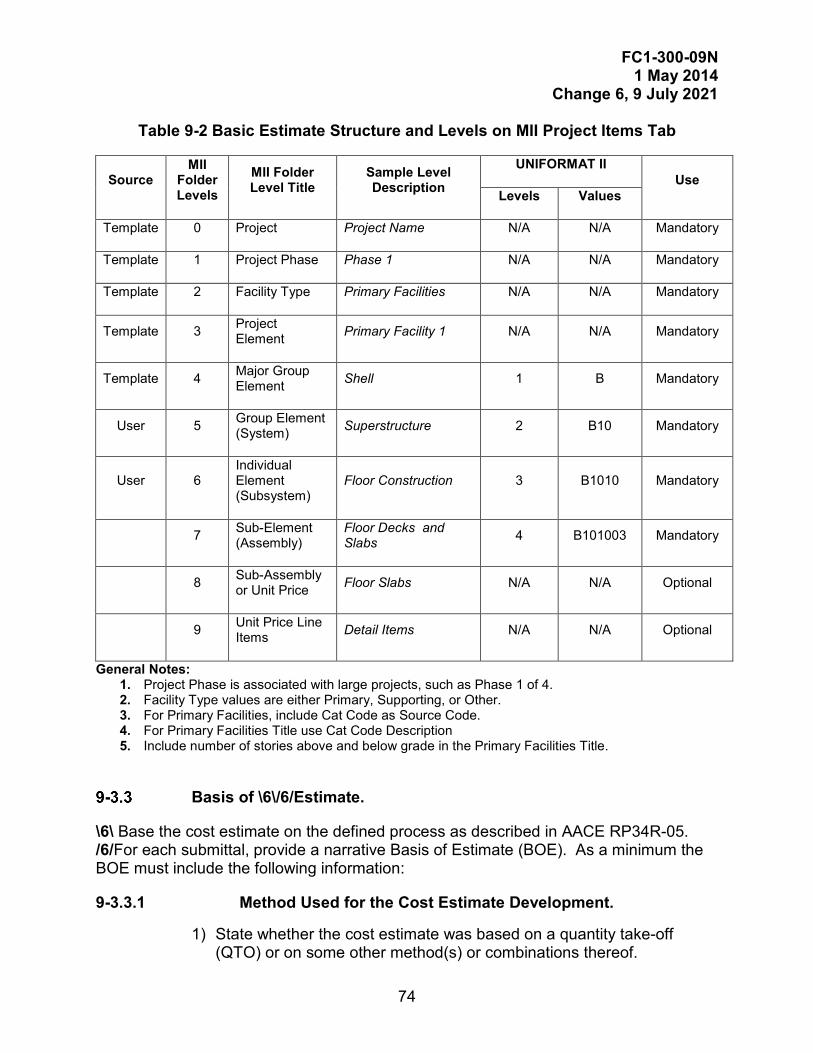
FC1-300-09N 1 May 2014
Change 6, 9 July 2021
74
Table 9-2 Basic Estimate Structure and Levels on MII Project Items Tab
Source MII
Folder Levels
MII Folder Level Title
Sample Level Description
UNIFORMAT II Use
Levels Values
Template 0 Project Project Name N/A N/A Mandatory
Template 1 Project Phase Phase 1 N/A N/A Mandatory
Template 2 Facility Type Primary Facilities N/A N/A Mandatory
Template 3 Project Element Primary Facility 1 N/A N/A Mandatory
Template 4 Major Group Element Shell 1 B Mandatory
User 5 Group Element (System) Superstructure 2 B10 Mandatory
User 6 Individual Element (Subsystem)
Floor Construction 3 B1010 Mandatory
7 Sub-Element (Assembly)
Floor Decks and Slabs 4 B101003 Mandatory
8 Sub-Assembly or Unit Price Floor Slabs N/A N/A Optional
9 Unit Price Line Items Detail Items N/A N/A Optional
General Notes: 1. Project Phase is associated with large projects, such as Phase 1 of 4. 2. Facility Type values are either Primary, Supporting, or Other. 3. For Primary Facilities, include Cat Code as Source Code. 4. For Primary Facilities Title use Cat Code Description 5. Include number of stories above and below grade in the Primary Facilities Title.
Basis of \6\/6/Estimate.
\6\ Base the cost estimate on the defined process as described in AACE RP34R-05. /6/For each submittal, provide a narrative Basis of Estimate (BOE). As a minimum the BOE must include the following information:
9-3.3.1 Method Used for the Cost Estimate Development.
1) State whether the cost estimate was based on a quantity take-off (QTO) or on some other method(s) or combinations thereof.
FC1-300-09N 1 May 2014
Change 6, 9 July 2021
75
2) For each submittal provide the design basis for the estimate and whether or not the design deliverables are sufficient to support the estimate class required in Table 9-1 above.
Describe all of the design deliverables used as the design basis for the estimate. This includes drawings, specifications, basis of design, studies, reports, and site engineering investigation.
Discuss the classification and the basis of that classification relative to the maturity level of the design at the time of submission. The design maturity discussion is to include general project data and the design deliverables indicated in this FC, including the referenced AACE RP 56R-08. Indicate specifically which of the minimum design deliverables need to be completed in order to achieve the required estimate class. Describe the overall maturity of the design deliverables as a whole and the resulting expected accuracy range expressed as a high and low value around the 50% confidence level (P50). \6\ /6/
Provide a qualitative analysis of the current construction market an any expectation for changes through the planned construction period at the project location. This is to include availability of labor and materials and market drivers. Indicate the sources of information used in the market analysis.
Include a specific statement indicating whether or not the estimate is based on the final design.
3) \6\Discuss the use of Contract Line Items within the estimate./6/
9-3.3.2 Cost Estimate Details.
1) Describe the anticipated acquisition strategy and expected level of competition.
2) Include the assumed minimum number of bidders. \6\
3) Include how much work is being self-performed by the Prime and how much and what type of work is being subcontracted out. /6/
4) Provide a summary of key assumptions.
5) Include other execution factors that may impact bid costs such as:
Phasing
Access restrictions
FC1-300-09N 1 May 2014
Change 6, 9 July 2021
76
Working hours
Overtime \6\
6) Describe how the estimate accounts for the current construction market, including mark-ups applied. /6/
7) Contractor markups used: Include detailed discussion backed up by industry data and/or calculations justifying percentages used for Home Office Overhead, Job Office Overhead, Profit, Bond, Taxes, \6\ Competition Premium, /6/ and any markup on sub-contractors. Provide this information for the prime contractor and all subcontractors. Do not make broad statements such as “based on historical data.”
8) List and explain the use of other markups such as design allowances (including allowances to address any assumptions made pertaining to any studies/reports), bonds, gross receipts tax (GRT), and other taxes.
9) Address costs for underdeveloped design or other items of uncertain scope through the use of clearly defined user cost items in the form of allowances. These allowances are to include costs for labor, material and equipment and are to be assigned to the appropriate contractor in the estimate. Prepare a table listing each allowance, the associated contractor, the location(s) in the estimate and the contract cost for each allowance item. Provide the total contract cost of all allowances.
10) List and explain the General Requirements (Job Office Overhead) and Home Office Overhead rates used in the estimate. The duration of field overhead costs is to be informed by the general construction schedule. \6\ Prime JOOH and General requirements cost items must be included in the detailed estimate and represented as a calculated contractor mark-up. /6/
11) Provide a summary of key risks associated with the cost estimate itself as well as any other items which could directly or indirectly impact the overall cost.
12) Discuss the value of the point estimate (the current working estimate, CWE or the Independent Government Estimate, IGE \6\ prior to contingencies being applied /6/) as well as the range of probable values of the estimate. Include in this discussion the application of contingency applied to arrive at the CWE or the final IGE. \6\ /6
If a formal Cost and Schedule Risk Analysis (CSRA) is prepared as part of the project requirements, indicate where the \6\ point estimate falls in the range of probable values as determined by the CSRA. Identify the effective date of the CSRA with each submittal. Incorporate the following information from the CSRA into the BOE:
FC1-300-09N 1 May 2014
Change 6, 9 July 2021
77
i. Provide summary discussion of the CSRA that includes the key cost and schedule risk items driving contingencies in the cost and schedule. Present key recommendations that may assist in mitigating risks.
ii. Provide a Frequency View chart (Probability Density Function). Include markers for the mean and median values of the distribution.
iii. Provide a Cumulative Frequency Chart (Cumulative Distribution Function). Include markers for the mean and median values of the distribution.
iv. Provide the Statistics Table from the simulation.
v. Provide the Percentiles Table from the simulation.
If a formal CSRA is not prepared as part of the project requirement, \6\ the estimator should provide a defensible discussion on how any contingencies were developed and where the original point estimate falls within the range of probable values. /6/.
Identify the estimating software tools used - versions of PACES and MII./6/
9-3.3.3 Estimating Tools.
Provide information on the software tools and associated databases used in the development of the cost estimate.
9-3.3.4 Sources of Information.
1) Provide the basis for localized costing.
Detailed explanation of the source(s) of material and equipment unit costs used.
Basis of labor unit rates and burdens used (such as Construction Wage Rate Requirements Statute) including explanation for additional labor adjustments such as productivity, overtime, and shift work. For projects in remote locations (or in Guam) indicate if burdened unit rates assume use of non-local (or off-island) labor (for example, H-2B workers) and if so, indicate the percentages of local and non-local (or off-island) labor.
UFC 3 701 01 precludes the use of Area Cost Factors to modify parametric cost estimates, detailed quantity take-off estimates, unit

FC1-300-09N 1 May 2014
Change 6, 9 July 2021
78
price book line items, commercial cost data, or user generated unit costs.
OCONUS Projects: Adjust all costs for OCONUS projects to reflect construction costs in the Host Nation. Develop localized cost adjustments to reflect appropriate costs. The use of cost factors developed for programming level estimates are not acceptable for making these localization adjustments. Provide a copy of the localized pricing data and a narrative discussion of the source of the data.
2) Provide escalation calculations and source of escalation factor used, such as the “NAVFAC Building Cost Index (BCI) Consistent with DoD UFC 3-701-01.” Future escalation guidance may be provided by the NAVFAC Cost TDC in certain markets. The latest BCI may be found on the Whole Building Design Guide under the NAVFAC page \5\ (https://www.wbdg.org/ffc/navy-navfac/cost-engineering-guidance-ceg) /5/. \6\Escalate cost items from the source date to the midpoint of construction or an alternate date as approved by the NAVFAC Cost Engineer./6/
3) Indicate the midpoint of construction developed at each submittal and provide an explanation of how the construction duration was developed for the project. The midpoint of construction must be developed from the Project Schedule.
4) Inform and incorporate dates of the construction schedule into the cost estimate. Discuss the reasonableness of the proposed construction schedule to meet the contract award within the authorization year or meeting the defined Initial Operational Capability (IOC) date.\6\
9-3.3.5 Estimate Progression.
At each submittal, compare the project cost to the Certified Final DD1391 Block 9 costs. Evaluate and discuss the causes of variances exceeding 10% of any cost line items, subtotals, or totals.
After the first submittal, compare subsequent cost estimate submittals to the previously submitted cost estimate. Evaluate and discuss the causes of variances exceeding 10% of any UNIFORMAT II Level 1 and Level 2 cost elements, sub-totals, or totals.
CONTRACT LINE ITEMS (CLINS).
Price CLINS developed, as described in Chapter 10, within the cost estimate and identify consistently with the CLINS and sub-CLINS for base bid items as well as any option or additive items. Maintain the use of the specified WBS for each CLIN and sub-CLIN. Use alternate contractors as necessary in the estimate to ensure that the overhead costs are appropriately distributed for option or additive items.
FC1-300-09N 1 May 2014
Change 6, 9 July 2021
79
COST AND SCHEDULE RISK ANALYSIS (CSRA).
When required by the scope of services, perform the Cost and Schedule Risk Analysis (CSRA) in accordance with \6\UFC 3-740-05 and with U.S. Army Corps of Engineers (USACE) “Cost and Schedule Risk Analysis (CSRA) Guidance located at http://www.nww.usace.army.mil/Missions/Cost-Engineering/. Provide the native Excel macro-enabled CSRA model file. Develop CSRA models using the Crystal Ball add-in to MS Excel unless otherwise approved by the NAVFAC Cost Technical Discipline Coordinator (TDC). Base the default contingency on a 50% Confidence Level. Include this contingency in the baseline estimate as the Risk Contingency owner markup (NAVFAC MII template) or as directed by the NAVFAC Cost TDC. Incorporate the key findings from the CSRA process in the BOE. In addition, provide a copy of the risk register.
Update the CSRA and submit for review with each design submittal. Use the CSRA output and report to arrive at the range of possible costs and discuss the current value of the cost estimate relative to that range. Indicate the level of design development and the effective date of the cost estimate and construction schedule used in each CSRA submittal.
CONSTRUCTION SCHEDULE.
Provide a construction schedule in support of the cost estimate and CSRA. Use the duration, crew hours, and labor hours in the estimate to develop the construction schedule. In turn, the estimate must include itemized job overhead costs based on the results of the construction schedule. Running job overhead percentages may be permitted on Class 4 and Class 5 estimates, but must not be used on Class 1, Class 2 or Class 3 estimates unless approved by the NAVFAC Cost Engineer. The schedule is to be roughly equivalent to a Level 3 Estimate as defined in AACE Recommended Practice 91R-16 Schedule Development. It must define critical activities but is not required to be resource loaded. It must follow the UNIFOMAT II Work Breakdown Structure (WBS) used in the estimate. The WBS is to be displayed at least to Level 3 of UNIFORMAT II but is not be required to be displayed any lower than Level 3. This schedule is part of the cost estimate supporting documentation and will not be shared with the Contractor.
VALUE ENGINEERING STUDIES (VES)
When VES are required by the scope of services, provide in accordance with Appendix D3. /6/

FC1-300-09N 1 May 2014
Change 6, 9 July 2021
80
This Page Intentionally Left Blank
FC1-300-09N 1 May 2014
Change 6, 9 July 2021
81
DELIVERABLE: CONTRACTING REQUIREMENTS
GENERAL REQUIREMENTS.
The Contract Specialist incorporates Contract Line Items (CLINs) from the information provided in the Project Information Form (PIF) and Document 00 22 13.00 20, Supplementary Instructions to Offerors. Provide and submit the PIF and UFGS Document 00 22 13.00 20 in Microsoft Word or Adobe PDF format, to the Government Project Manager who will provide it to the Contracting Specialist.
PROJECT INFORMATION FORM (PIF).
Prepare and provide a Project Information Form (PIF); attach the completed UFGS Document 00 22 13.00 20 to it. The PIF communicates to the Contract Specialist which contract clauses to include in the solicitation. The Government representative forwards the PIF to the Contracting Specialist to prepare the contract clauses for the solicitation. A downloadable version of the PIF is available at\5\ https://www.wbdg.org/ffc/navy-navfac/project-information-form-specifications-cover-sheet./5/
SELECTION OF CLINS.
The Base Contract Line Item must provide a complete and usable facility (primary facility, supporting facilities, and design in accordance with previous paragraph). Option items and additive items must be able to be logically separated from the project without rendering the facility unusable. Intention is for the Base CLIN, together with all the contract line items, to provide the maximum, usable facility within the funds available. Do not use Additive and Option items in the same contract; use one or the other. Additive items are only allowed for sealed bids; do not use unless allowed by Contracting Officer.
Use multiple SUB-CLINs for cost breakdown of facilities and site, and unit prices. Use multiple CLINS for multiple funding sources (such as when combining one or more projects into one contract package), and option or additive line items. Provide separate SUB-CLINs for 1) Each facility (as indicated by the Category Code), 2) The total project supporting facility (utility) cost (outside the five foot (1.5 m) line, and 3) Design Fee (if a Design-Build project). The number of items and the estimated cost per item depends upon the nature of the project. Provide no more than four contract line items (base item, plus three), unless specifically approved by the Contracting Officer. Each estimated option or additive item should tend to approximate 2% to 10% of the estimated base item.
OPTIONS AND ADDITIVES ON DRAWINGS.
Options and Additives can change up to award of the contract. Do not indicate Contract Line Items on the drawings, or reference anywhere in the specifications, unless approved by the Government, who may allow only if a description of the line item in schedule does not adequately describe the work. Samples of Document 00 22 13.00 20 are provided in Appendix C.

FC1-300-09N 1 May 2014
Change 6, 9 July 2021
82
Do not use the term “alternate” to represent line items. Do not use terms, such as “base item” to indicate items in the primary contract line item.
OPTION ITEMS.
When different funding sources are used, or when funding is not available to cover certain portions of the work at the time of proposal opening, but there exists a high probability of attaining the funding in the near future, option items provide a means to separate the funding sources, or to obtain and hold competitive prices for future award of items of work. Typically, the price for the option item(s) is added to the base item price to determine the low offer. Options need not be listed in a particular order. They are executed individually at the Government’s discretion. A time limit is given in the contract documents for the Government’s right to execute each option. Use of options in construction contracts must be approved by the Contracting Officer prior to advertisement.
ADDITIVE ITEMS.
Since additive line items are only allowed in sealed bid, do not use these unless allowed by the Contracting Officer. If used, arrange additive items such that the most essential portion of the work is added first. Arrange succeeding items in decreasing importance. During evaluation of the offers, additive items are added to the base item in the order listed. As each additive item is added, a new bid price is computed and compared to the available funds. As additive items are determined to be within the funds available they are added to the Offeror’s bid price. If they are not within the funds available, they are skipped. Each additive item must be independent of the others.
DEDUCTIVE ITEMS.
Do not use deductive items. The base contract line item must contain the minimum requirements of the contract. Using deductive items implies that the project is designed above those minimum requirements. Use Options instead.
PLANNED MODIFICATION ITEMS.
Planned Modifications are changes to the contract that the Government can only award after the initial award of the contract, due to the nature of the work. Award time of a planned modification is measured from construction completion date (usually 6 months prior to completion), rather than award date. This differentiates them from Option Items.
Planned funding for Furniture, Fixtures and Equipment (FF&E) is from a different source than the Base Contract Line Item. Therefore, provide a separate CLIN for the purchase and installation coordination of all FF&E; designate it as a Planned Modification. The Offeror must propose a Handling and Administration (HAR) not to exceed 5% within this CLIN which will be applied to the final FF&E package amount at modification award. HAR is limited to 5% for NAVFAC in accordance with NAVFAC Furniture, Fixtures and Equipment (FF&E) Contracting Guide for Design-Build Construction Projects, which is also valid for Design-Bid-Build Projects by Amendment, and available for download by

FC1-300-09N 1 May 2014
Change 6, 9 July 2021
83
NAVFAC employees at \1\https://hub.navfac.navy.mil:443/webcenter/content/conn/WebCenterSpaces-ucm/path/Enterprise%20Libraries/aq/Legacy%20%28Will%20Be%20Deleted%29/Files/AQ_HI/9---9648628bc9974c17910abfe04400144f414f26?lve/1/.
SYNOPSIS.
Provide a brief scope for the project synopsis, which is used in solicitation of bids by the Government. Describe facility in terms of square footage (or square meters), height (\3\such as/3/ 2-story). A sample of scope and Synopsis is provided in Appendix C.

FC1-300-09N 1 May 2014
Change 6, 9 July 2021
84
This Page Intentionally Left Blank.
FC1-300-09N 1 May 2014
Change 6, 9 July 2021
85
DELIVERABLE: DESIGN-BUILD REQUEST FOR PROPOSAL (RFP)
GENERAL REQUIREMENTS.
Requirements for preparation of RFP are also provided in Chapter 12, Electronic Design Deliverables (EDD) Format.
DESIGN-BUILD REQUEST FOR PROPOSAL INTRODUCTION.
NAVFAC Design-Build (DB) RFPs are developed by organizing project requirements into the NAVFAC DB Six Part Format to procure facilities for our Navy Customers and Users. Requirements included in the RFP are driven by the need to control the design and the construction of the facility. Because the Contractor is designing and constructing the facility, design issues are just as important as construction issues and must be given equal consideration. The RFP information may be gathered from many sources such as:
• DD Form 1391 Documentation
• Funding Documents
• Site conditions and Restraints
• User Requirements
• Local and Regional Requirements
• Applicable Standards and Codes
• Applicable NAVFAC and DoD Criteria and Clauses
• Performance and Prescriptive Product, Material, and System Requirements
RFPs are a combination of performance and prescriptive requirements, but give preference to performance requirements for DB. However, many times prescriptive requirements are necessary to define a minimum acceptable solution or expected level of quality. Therefore, mold the type of information included in the RFP to meet the anticipated level of quality and needs of the User. Create performance and prescriptive requirements that comply with the following characteristics of each.
• Performance requirements state the function, desired results, and durability to control the Contractor’s design and selection of products, materials, and systems.
• Prescriptive requirements define the products, materials, and system or their characteristics to control the facility function, performance, and quality.
FC1-300-09N 1 May 2014
Change 6, 9 July 2021
86
DESIGN-BUILD REQUEST FOR PROPOSAL WEBSITE, FORMAT, AND DOCUMENTS.
Guidance on preparing the RFP for Design-Build projects and Design-Build Template documents are available on the NAVFAC Design-Build Master web site (http://www.wbdg.org/ndbm). This site is intended to (1) familiarize those new to the NAVFAC Design-Build process with the RFP format and typical RFP specification sections and (2) allow those preparing a Design-Build RFP to download the current and archived electronic documents. The Design-Build RFP web site is organized using links to major components of the Design-Build RFP, including:
• Overview and Training - NAVFAC RFP Format, Uniformat Information Structures, and NAVFAC Technical Contacts responsible for document maintenance.
• Design Guidance.
• Standard Template – This is the foundation template that can be used on all projects. The Standard Template is designed to cover most of the building types routinely designed and built by NAVFAC. Industrial and specialized facilities are examples of building types that require additional information to be added to the Standard Template to cover the design, materials, and equipment that are unique to these buildings types.
• Model RFP Templates - The Model RFP Templates use the Standard Template as its foundation. Each Model Template modifies the Standard Template to suit a particular building type. These Models are an advanced starting point toward creating an RFP, however they do require coordination with User and facility requirements to properly define the final RFP. The building type templates in the Design-Build Master Website are:
o Armory o Child Development Centers o Dining Facility o Entry Control Facility o Fire Station o Fitness Center o Hangar o Magazine o Marine Corp BEQ o Market Style BEQ
• Small Project Template (SPT): The SPT is a scaled down version of the Standard Template to be used on projects of low-complexity and a limited
FC1-300-09N 1 May 2014
Change 6, 9 July 2021
87
number of construction trades. SPT projects utilize routine designs with limited plans & specifications and fit within monetary thresholds.
o A tool located with the SPT at web link: \1\ http://www.wbdg.org/ndbm/pdfs/decision_guidance_navfac_spdb.pdf /1/ includes a table “Decision Guidance for Use of Small Project Design-Build Process” to provide guidance in the application of the SPT.
RFP Format.
The RFP must include all six RFP Parts indicated below unless they are not applicable to the project. The typical facility project will have information in every RFP Part, with the possible exception of RFP Part Five, “Prescriptive Specifications.” Typically, Part One is not prepared by the RFP developer, but is provided by the NAVFAC Acquisition office after RFP Parts Two through Six have been completed by the RFP developer. The RFP developer is required to provide certain information such as the Project Information Form (PIF) for the NAVFAC Acquisition office to properly prepare the RFP Part One. Verify with the NAVFAC Facility Engineering Command, what provisions are necessary to allow for the RFP Part One to be integrated into the RFP.
The DB Templates utilize different types of information in different Parts of the RFP. Therefore, there are different information structures employed to organize the information in the different RFP Parts. The following list indicates the type of information and information structures are used in the RFP Parts:
• Part One includes the Proposal Form and Documents and specifies the contractual requirements.
o This Part uses the Standard Procurement System documents that are organized using the CSI Masterformat.
• Part Two contains the General Requirements Specification Sections – some only available at the Design-Build website.
o This Part uses specification sections organized using CSI Masterformat.
• Part Three contains the Project Program for the project. o This Part predominately uses a paragraph format; Chapter Six of Part 3, the Engineering Systems Requirements uses Uniformat.
• Part Four contains the Performance Technical Specifications. o This Part uses Uniformat.
• Part Five contains any Prescriptive Specifications required for the Design-Build RFP.
o This Part uses CSI Masterformat.

FC1-300-09N 1 May 2014
Change 6, 9 July 2021
88
• Part Six includes attachments to define existing conditions and design requirements (\3\such as/3/ Boring Logs, reference drawings).
o This Part is a combination of various attachments that have no predominate format.
Recommend Change to DB Documents.
Submit a Contract Change Request (CCR) on the DB website to recommend a change to the DB documents.
DESIGN-BUILD REQUEST FOR PROPOSAL DOCUMENT PREPARATION.
The DB documents are updated and changed regularly. Because the DB documents change regularly, it is necessary to use the updated documents when creating an RFP. Download the most current versions available on the DB website. Each DB Template and Model RFP Templates has a DOWNLOAD feature. Download individual documents or all documents organized into RFP Parts.
Combining Multiple RFPs into One Bid Package.
Refer to Chapter 8 for guidance, when multiple RFPs are combined into one solicitation package.
Project Information Form (PIF).
Provide and complete the PIF for Prefinal and Final submittals. Refer to Chapter 8 for further PIF requirements.\3\/3/
RFP ELECTRONIC DELIVERABLES.
Provide RFP electronically in accordance with Chapter 12, Electronic Design Deliverables (EDD) Format. Organize the RFP into one or two PDF files, with order shown in the following Table of Contents. Bookmark each item below, and the additional items indicated.
1) RFP Coversheet
2) RFP PART 1 Divider (when directed by the Command)
3) Overall, RFP Table of Contents (Parts 2-6)
4) RFP PART 2 Divider
RFP Part 2 Table of Contents
RFP Part 2 Specification Sections (bookmark first page of each section)
FC1-300-09N 1 May 2014
Change 6, 9 July 2021
89
5) RFP PART 3 Divider
RFP Part 3 Project Program Coversheet
RFP Part 3 Table of Contents
RFP Part 3 Project Program
Each Chapter of RFP Part 3 (bookmark first page)
Each ESR in Chapter 6 (bookmark first page)
6) RFP PART 4 Divider
RFP Part 4 Table of Contents
RFP Part 4 Performance Technical Specifications (bookmark first page of each PTS)
7) RFP PART 5 Divider (if prescriptive specifications are included in the RFP)
RFP Part 5 Table of Contents
RFP Part 5 Specification Sections (bookmark first page of each section)
8) RFP PART 6 Divider
RFP Part 6 Table of Contents
(1) Attachments (bookmark first page of each attachment)
DB DESIGN SUBMITTALS.
Provide design submittals electronically in accordance with Chapter 12, Electronic Design Deliverables (EDD) Format. Include information and organize DB design submittals in accordance with this FC and UFGS 01 33 10.05 20, Design Submittal Procedures.
DESIGN AND CONSTRUCTION SUBMITTAL REQUIREMENTS.
Because the DB projects require design and construction submittals, the submittals are more complex than Design-Bid-Build. The DB process utilizes the RFP and the UFCs to define design submittals and the RFP and the UFGS to define construction submittals.
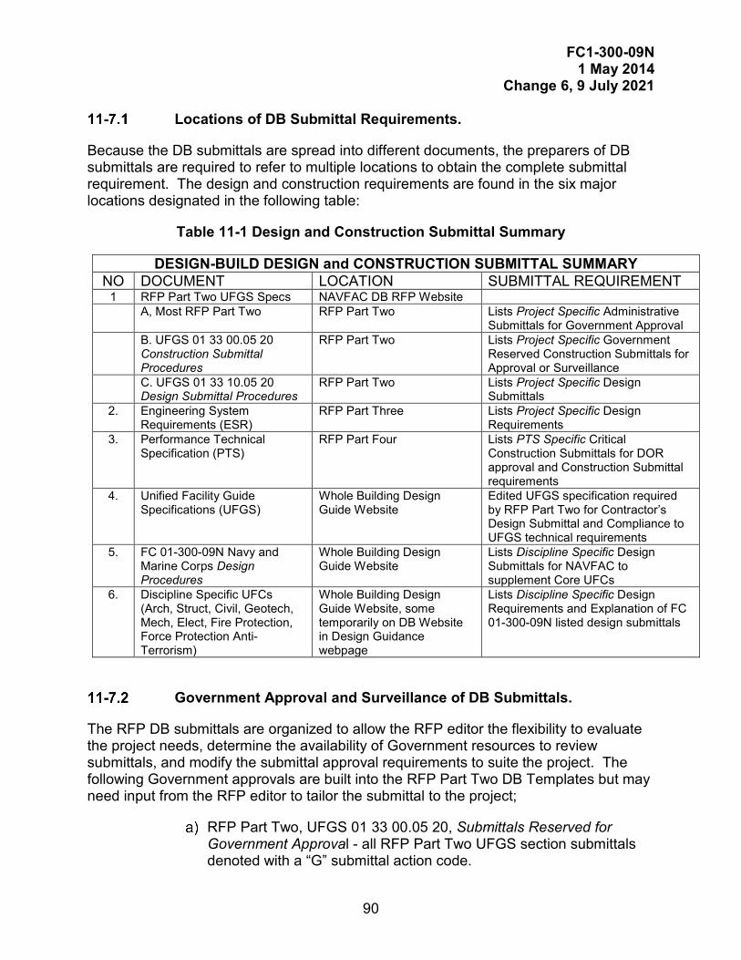
FC1-300-09N 1 May 2014
Change 6, 9 July 2021
90
Locations of DB Submittal Requirements.
Because the DB submittals are spread into different documents, the preparers of DB submittals are required to refer to multiple locations to obtain the complete submittal requirement. The design and construction requirements are found in the six major locations designated in the following table:
Table 11-1 Design and Construction Submittal Summary
DESIGN-BUILD DESIGN and CONSTRUCTION SUBMITTAL SUMMARY NO DOCUMENT LOCATION SUBMITTAL REQUIREMENT
1 RFP Part Two UFGS Specs NAVFAC DB RFP Website A, Most RFP Part Two RFP Part Two Lists Project Specific Administrative
Submittals for Government Approval B. UFGS 01 33 00.05 20
Construction Submittal Procedures
RFP Part Two Lists Project Specific Government Reserved Construction Submittals for Approval or Surveillance
C. UFGS 01 33 10.05 20 Design Submittal Procedures
RFP Part Two Lists Project Specific Design Submittals
2. Engineering System Requirements (ESR)
RFP Part Three Lists Project Specific Design Requirements
3. Performance Technical Specification (PTS)
RFP Part Four Lists PTS Specific Critical Construction Submittals for DOR approval and Construction Submittal requirements
4. Unified Facility Guide Specifications (UFGS)
Whole Building Design Guide Website
Edited UFGS specification required by RFP Part Two for Contractor’s Design Submittal and Compliance to UFGS technical requirements
5. FC 01-300-09N Navy and Marine Corps Design Procedures
Whole Building Design Guide Website
Lists Discipline Specific Design Submittals for NAVFAC to supplement Core UFCs
6. Discipline Specific UFCs (Arch, Struct, Civil, Geotech, Mech, Elect, Fire Protection, Force Protection Anti- Terrorism)
Whole Building Design Guide Website, some temporarily on DB Website in Design Guidance webpage
Lists Discipline Specific Design Requirements and Explanation of FC 01-300-09N listed design submittals
Government Approval and Surveillance of DB Submittals.
The RFP DB submittals are organized to allow the RFP editor the flexibility to evaluate the project needs, determine the availability of Government resources to review submittals, and modify the submittal approval requirements to suite the project. The following Government approvals are built into the RFP Part Two DB Templates but may need input from the RFP editor to tailor the submittal to the project;
RFP Part Two, UFGS 01 33 00.05 20, Submittals Reserved for Government Approval - all RFP Part Two UFGS section submittals denoted with a “G” submittal action code.
FC1-300-09N 1 May 2014
Change 6, 9 July 2021
91
RFP Part Two, UFGS 01 33 10.05 20, Government Approving Authority – Government approves all design submittals.
RFP Part Two, UFGS 01 33 10.05 20, Exception to Contractor Construction Actions – Identifies certain Government design submittals approvals that have to be accomplished before construction related to that design submittal can begin.
RFP Part Two, UFGS 01 33 10.05 20, Design Documents, and UFGS 01 33 00.05 20, Contractor Reviewing, Certifying, Approving Authority - Government identified construction submittals required to be incorporated in the design submittals. DOR approval of identified construction submittals precedes Government approval of associated design submittals.
RFP Part Two, UFGS 01 33 00.05 20, Submittals Reserved for Government Approval - Construction submittals reserved for Government approval. The approval of these identified construction submittals prevents the contractor from beginning construction on that portion of the work until Government approval is obtained.
11-7.2.1 Surveillance Submittals.
The Government requires the contractor’s DOR to approve most of the construction submittals; however, the RFP identifies certain construction submittals for Government surveillance. Government surveillance does not prevent the contractor from proceeding with construction but allows the Government a chance to confirm the submittal approvals of the DOR. Surveillance of construction submittals are built into the DB Template at the following location:
RFP Part Two, UFGS 01 33 00.05 20, Submittals Reserved for Government Surveillance - Construction Submittals Reserved for Government surveillance.
11-7.2.2 Critical Path Submittals.
Contractor submittals in Design-Build may be designated as Critical Path Submittals, as further described in UFGS 01 33 10.05 20 of the RFP. In this situation, the submittal may only contain the design of one or a few disciplines, for example, civil and structural. Follow the submittal requirements as applicable for the disciplines pertaining to that critical path submittal. Ensure that work is included and coordinated with the other disciplines that are affected by that critical path work; for example, electrical and mechanical site work is included and shown on the civil site work critical path submittal, and provisions are made for the utility service entrances through foundation and for major pieces of equipment for the foundation work critical path submittal.

FC1-300-09N 1 May 2014
Change 6, 9 July 2021
92
This Page Intentionally Left Blank
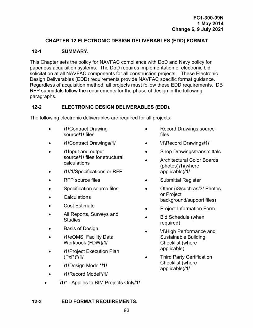
FC1-300-09N 1 May 2014
Change 6, 9 July 2021
93
ELECTRONIC DESIGN DELIVERABLES (EDD) FORMAT
SUMMARY.
This Chapter sets the policy for NAVFAC compliance with DoD and Navy policy for paperless acquisition systems. The DoD requires implementation of electronic bid solicitation at all NAVFAC components for all construction projects. These Electronic Design Deliverables (EDD) requirements provide NAVFAC specific format guidance. Regardless of acquisition method, all projects must follow these EDD requirements. DB RFP submittals follow the requirements for the phase of design in the following paragraphs.
ELECTRONIC DESIGN DELIVERABLES (EDD).
The following electronic deliverables are required for all projects:
• \1\Contract Drawing source/1/ files
• \1\Contract Drawings/1/ • \1Input and output
source/1/ files for structural calculations
• \1\/1/Specifications or RFP
• RFP source files
• Specification source files
• Calculations
• Cost Estimate
• All Reports, Surveys and Studies
• Basis of Design
• \1\eOMSI Facility Data Workbook (FDW)/1/
• \1\Project Execution Plan (PxP)*/1/
• \1\Design Model*/1/ • \1\Record Model*/1/
• Record Drawings source files
• \1\Record Drawings/1/ • Shop Drawings/transmittals
• Architectural Color Boards (photos)\1\(where applicable)/1/
• Submittal Register
• Other (\3\such as/3/ Photos or Project background/support files)
• Project Information Form
• Bid Schedule (when required)
• \1\High Performance and Sustainable Building Checklist (where applicable)
• Third Party Certification Checklist (where applicable)/1/
• \1\* - Applies to BIM Projects Only/1/
EDD FORMAT REQUIREMENTS.
FC1-300-09N 1 May 2014
Change 6, 9 July 2021
94
Specifications.
Develop Project Specifications in accordance with the requirements of this FC and UFC 1-300-02, using SpecsIntact software. Organization of PDF for Specifications is described in Chapter 8. Organization of PDF for RFP is described in Chapter 11.
12-3.1.1 \1\Specification/1/ Source Files.
From the SpecsIntact Job File, provide the following source files: “Pulldata” and “Submittal Register.” “Printdata” does not have to be provided.
12-3.1.2 DB RFP Part 2 Source Files.
Develop RFP and Part 2 specifications in accordance with Chapter 11 of this FC.
If a program other than SpecsIntact is allowed to be used, all original source data must be provided as follows:
• The native authoring application file format.
• A PDF format print of the original authoring data. No scans, copied images or third party reproductions of paper prints will be accepted.
\1\\2\Electronic Operation and Maintenance Support Information
(eOMSI)/2/ Facility Data Workbook (FDW).
When required by the contract, \2\provide the /2/Excel workbook, which contains the Model & Facility Data Matrix tab (used to \2\select/2/ Mastersystems, Systems and Subsystems included in the design). Use the original eOMSI FDW source file\2\, as referenced in Appendix A, for each project./2/
Complete the eOMSI FDW in accordance with the Instructions tab of the eOMSI FDW./1/
Drawings.
12-3.3.1 /1/Drawing Definitions.
12-3.3.2 Drawing Source Files.
Produce all source drawings using vector based Computer Aided Design (CAD) software. Provide all source drawing files in native DWG format meeting the following requirements.
Contract Drawing Source Files.
The native DWG CAD files \3\(such as/3/ plans, elevations, sections, details) created by the DOR for the project. The Contract Drawing Source Files are not the legal record of the project Design.
FC1-300-09N 1 May 2014
Change 6, 9 July 2021
95
Contract Drawings.
The PDF files created from the Contract Drawing Source Files that represent the scope of the projects. The Contract Drawings are the legal record of project Design which are awarded to the construction contractor (KTR) \6\which includes amendments/6/.
As-Built Drawings.
The hard copy prints of the Contract Drawings marked up by the KTR (as required by the project specifications) to represent approved changes to the Contract Drawings.
Record Drawing Source Files.
The Contract Drawing Source Files edited by the KTR or DOR (depending on contract requirements) to reflect the changes shown on the approved As-Built Drawings. Prepare Record Drawing Source Files as described in this Chapter, Record Drawing Preparation. Record Drawing Source Files are not a legal record of the Project.
Record Drawings.
The PDF files created from the Record Drawing Source Files that represent the final installed condition of the project. Prepare the project Record Drawings as described in this Chapter, Record Drawing Preparation. The Record Drawings are the legal record of the completed project.
12-3.3.3 Drawing Progression
Naming conventions and procedures as drawing progresses through design, construction, and post-construction are indicated in Figures 12-1 and 12-2.
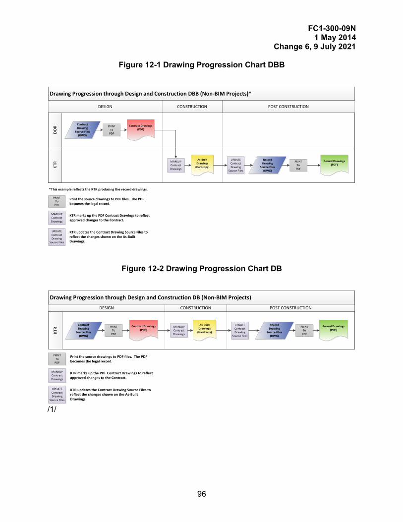
FC1-300-09N 1 May 2014
Change 6, 9 July 2021
96
Figure 12-1 Drawing Progression Chart DBB
Drawing Progression through Design and Construction DBB (Non-BIM Projects)*
KTR
DOR
POST CONSTRUCTIONDESIGN CONSTRUCTION
ContractDrawing
Source Files (DWG)
Contract Drawings(PDF)
As-Built Drawings
(Hardcopy)
Record Drawings(PDF)
Record Drawing
Source Files (DWG)
PRINTTo
UPDATEContract Drawing
Source Files
PRINTTo
MARKUPContract Drawings
PRINTTo
Print the source drawings to PDF files. The PDF becomes the legal record.
MARKUPContract Drawings
KTR marks up the PDF Contract Drawings to reflect approved changes to the Contract.
KTR updates the Contract Drawing Source Files to reflect the changes shown on the As-Built Drawings.
UPDATEContract Drawing
Source Files
*This example reflects the KTR producing the record drawings.
Figure 12-2 Drawing Progression Chart DB
Drawing Progression through Design and Construction DB (Non-BIM Projects)
KTR
POST CONSTRUCTIONDESIGN CONSTRUCTION
PRINTTo
Print the source drawings to PDF files. The PDF becomes the legal record.
MARKUPContract Drawings
KTR marks up the PDF Contract Drawings to reflect approved changes to the Contract.
KTR updates the Contract Drawing Source Files to reflect the changes shown on the As-Built Drawings.
UPDATEContract Drawing
Source Files
ContractDrawing
Source Files (DWG)
Contract Drawings(PDF)
As-Built Drawings
(Hardcopy)
Record Drawings(PDF)
Record Drawing
Source Files (DWG)
PRINTTo
UPDATEContract Drawing
Source Files
PRINTTo
MARKUPContract Drawings
/1/
FC1-300-09N 1 May 2014
Change 6, 9 July 2021
97
12-3.3.4 CAD Standards.
Comply with the DoD A/E/C CAD Standard latest version except as noted below. The A/E/C CAD standard is available at \5\ https://cadbimcenter.erdc.dren.mil/aeccadstandard or https://www.wbdg.org/ffc/army-coe/cad-bim-technology-center./5/ In cases where the DoD A/E/C CAD Standard version changes after a project has commenced, the project PM must be consulted prior to adoption and integration of the newer standard into the drawing \1\source/1/ files.
In cases where the DoD A/E/C CAD Standard does not provide guidance for (or reference to) a specific CAD Standard element, refer to the referenced National CAD Standards (NCS) document identified in the DoD A/E/C CAD Standard for guidance. In all cases, the project PM must be consulted.
NAVFAC Standard Drawing Format.
All sheet drawings must use the NAVFAC standard title block (border sheet). Provide all sheet drawings in ANSI D (22 x 34 inches) size format for projects using imperial units. Provide all sheet drawings in ISO A1 (594 x 841 mm) for projects using metric units (ANSI D is assumed in other parts of this FC, but modify and scale as appropriate if ISO A1 is used). See this chapter’s paragraph “NAVFAC Supported EDD Standard Components.”
All \1\source/1/ drawings must contain only (1) one plotted sheet. \1\Drawing source/1/ files which contain more than one sheet will be rejected with the following exceptions:
• Civil Sheet Files and other site plans (such as site utilities - electrical and telecommunications) in which the entirety of the project site cannot be legibly shown on a single sheet.
• Plan Sheet Files which the entirety of the project plan cannot be legibly shown on a single sheet at 1/8” = 1’– 0” (1 = 100) scale.
In both cases consult with the project PM prior to developing sheet files to ensure concurrence.
Plotting Guidelines.
Pen weights and colors must be in accordance with the NAVFAC pen table. NAVFAC has developed a comprehensive pen table that utilizes the NCS 255-pen table as a basis, but has added thinner lines and grayscale pens.
The NAVFAC pen tables are provided on the Whole Building Design Guide (WBDG) (See the paragraph in this Chapter entitled, “NAVFAC Supported EDD Standard Components”). This pen table and corresponding line weights were established to be legible when printed at half-size (11 x 17 inches (279 x 431 mm)), when the displayed text height is 1/16 inch (1.5 mm). All plotted files (hardcopy or PDF) must be monochrome, unless color plots are specifically requested. Use color numbers assigned to “black” or “halftone” only.
FC1-300-09N 1 May 2014
Change 6, 9 July 2021
98
Text Font and Size.
Use standard text heights for a plotted full-size drawing of 1/8 inch (3 mm) for typical text, 1/4 inch (6 mm) for titles, and 1 inch (25mm) maximum for project titles on cover sheets. For existing features on plotted full-size civil drawings, a minimum text height of 0.1 inch (2.5 mm) and an oblique angle of 12 degrees are allowed. Use a width factor of 0.8 for all fonts that are not a part of the border sheet.
• Use the ROMANS.SHX font file for all 1/8 inch (3 mm) or smaller text.
• Use SWISS.TTF (Swis721 BT) font file for all 1/4 inch (6 mm) or larger text.
In cases where a CAD program (see the paragraph in this chapter entitled, “CAD Standards”) does not support the specified font styles/format, \3\use ARIAL text font./3/ Notify the project PM prior to commencement of drawing development with the following information:
• Name, Version, File format and Vendor of CAD application being used
• Name of font(s) being substituted and name of substitute font(s)
• Copy of substitution font(s). Project PM confirmation of substitution is required to ensure font styles are acceptable.
Translations.
Construction drawings are required to be prepared in dual language at a majority of overseas locations. For drawings developed in dual language, provide adequate space for the foreign language translation for objects such as notes, titles, and symbols. The final drawing must not appear cluttered or congested. Provide translations (such as for notes, titles, and symbols) on Drawings with English on top, and the Host Nation language on the bottom. \6\Use italic font to distinguish the foreign language translation./6/
File Naming Conventions.
Use File Naming Convention for all CAD Files as specified in the DoD AEC CAD Standard except as noted below:
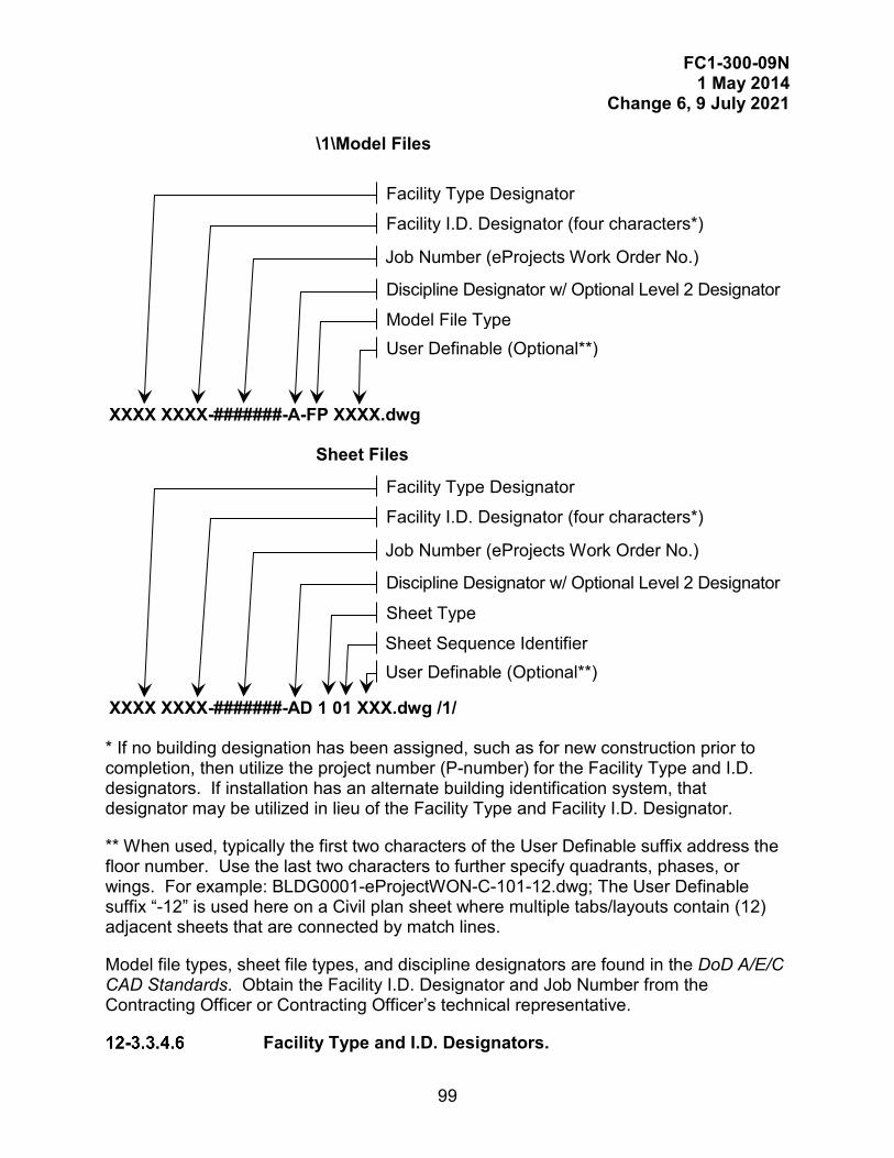
FC1-300-09N 1 May 2014
Change 6, 9 July 2021
99
\1\Model Files
Sheet Files
* If no building designation has been assigned, such as for new construction prior to completion, then utilize the project number (P-number) for the Facility Type and I.D. designators. If installation has an alternate building identification system, that designator may be utilized in lieu of the Facility Type and Facility I.D. Designator.
** When used, typically the first two characters of the User Definable suffix address the floor number. Use the last two characters to further specify quadrants, phases, or wings. For example: BLDG0001-eProjectWON-C-101-12.dwg; The User Definable suffix “-12” is used here on a Civil plan sheet where multiple tabs/layouts contain (12) adjacent sheets that are connected by match lines.
Model file types, sheet file types, and discipline designators are found in the DoD A/E/C CAD Standards. Obtain the Facility I.D. Designator and Job Number from the Contracting Officer or Contracting Officer’s technical representative.
Facility Type and I.D. Designators.
XXXX XXXX-#######-A-FP XXXX.dwg
Facility Type Designator
Facility I.D. Designator (four characters*)
Job Number (eProjects Work Order No.)
Discipline Designator w/ Optional Level 2 Designator
Model File Type User Definable (Optional**)
XXXX XXXX-#######-AD 1 01 XXX.dwg /1/
Facility Type Designator
Facility I.D. Designator (four characters*)
Job Number (eProjects Work Order No.)
Discipline Designator w/ Optional Level 2 Designator
Sheet Type
User Definable (Optional**) Sheet Sequence Identifier
FC1-300-09N 1 May 2014
Change 6, 9 July 2021
100
Use Facility Type and I.D. designators in Table 12-1.
Table 12-1 Facility Types and I.D. Designators
Facility Type AFLD = AIRFIELD BLDG = BUILDING DRDG = DREDGE DRYD = DRYDOCK BRTH = BERTH PIER = PIER SLIP = WET SLIP PRKG = PARKING LOT ROAD = ROAD RAIL = RAIL FENC = FENCE GATE = GATE UTIL = UTILITY CRAN = CRANE .
For Utility projects the Facility I.D. Designator must be as follows: SWTR = SALT WATER FWTR = FRESH WATER PWTR = POTABLE WATER NGAS = NATURAL GAS STEM = STEAM SSWR = SANITARY SEWER STRM = STORM DRAIN CAIR = COMPRESSED AIR POWR = POWER COMM = COMMUNICATIONS CATV = CABLE TV For Rail projects the Facility I.D. Designator must be as follows: CRAN = CRANE RAIL TRACK TRAK = RAILROAD TRACK
12-3.3.5 Drawing Support Files.
Support files necessary for initializing, editing and plotting drawing files must be a standard DWG or Microsoft Windows ® component (or they must be an integral and standard component within the drawing file that require no third party custom utility or program to use). Support files include, but are not limited to, line types, hatch patterns, font styles, layer filters, display configurations and object styles. DWG files containing objects, styles, or definitions that require any external files (\3\such as/3/ SHX, LIN or LAY) to initialize, operate and display properly will be rejected. 12-3.3.6 Cost Estimates.
Submit the contract cost estimate electronically in PDF and \4\MII (MCACES Second Generation) native format (or as otherwise required by contract) with each submittal./4/ Do not submit the cost estimate on the project CD/DVD when provided.\5\/5/
\6\Use the following File Naming Convention for MII files:
AFY_WON_P#_Short Description_Location_Submittal_Date/6/
FC1-300-09N 1 May 2014
Change 6, 9 July 2021
101
\1\Preliminary Design Documents.
Preliminary design includes all phases of Design except for the Final Design phase./1/ All source drawings and their associated PDFs must maintain a “PRELIMINARY Not For Construction” stamp across the signature areas of the title block, until the actual final design submittal. The NAVFAC D-size borders have this block on the default title block displayed on layer “G-ANNO-TTLB-PRLM”. That layer must be frozen at the time of creating the final deliverables. Except for the final submittal, indicate the submittal phase designation, such as “Prefinal”, after the project title in the header and on the coversheet of the specifications or the RFP. Combine all drawings into a single PDF file to facilitate ease of use, unless file size requires a multi-file submission.
Final Design Documents.
12-3.5.1 General.
Convert \1\source drawings/1/ to PDF format directly from their authoring software. Any drawing (DWG) files larger than 17Mb must be broken into smaller files. Drawing PDF file sizes must be a maximum of 17Mb with digital signatures. There is no limit on file size for specifications or RFPs.
12-3.5.2 Format of Final Design Drawings.
Combine all drawings into a single PDF file to facilitate ease of use, unless file size requires a multi-file submission. \3\ /3/ Bookmark PDF files and create visual “thumbnails.” Create a bookmark for the beginning of each drawing discipline. Create a sub-bookmark for individual drawing sheets. Bookmark wording must be as descriptive as practical \3\(such as/3/ S-101 Foundation Plan). When complete, the files must open to the “bookmarks” view as the default view with the drawing sheets visible in “fit to page” magnification. Before submission to NAVFAC, the professional must electronically sign and seal all sheets and appropriate locations on the NAVFAC Title Block(s) (See paragraph “NAVFAC Electronic Signature Requirements.”)
Multi-File Drawings.
If the PDF drawing set must be broken into several PDF sets due to the file size restrictions given in the paragraph in this chapter entitled, “\3\General/3/”, every attempt should be made to package complete discipline sets (do not break-up discipline specific sheets). 12-3.5.3 Format of Final Design Specifications.
Convert all specifications to PDF format directly from their authoring software. Combine specification sections into a single PDF file to facilitate ease of use. Insert PDF of attachments, such as Submittal Register and Environmental Forms, following the respective UFGS section and Bookmark.
FC1-300-09N 1 May 2014
Change 6, 9 July 2021
102
Preparation of PDF for Final Design Specification.
1) Merge PDF files for each section into one PDF file.
2) Combine the PDF files of the Coversheet, Table of Contents, and other project specific files including the Submittal Register. Insert blank pages where needed so that sections, graphics, and reports begin on an odd number page. Blank pages must include the following statement: “This Page Intentionally Left Blank.” Create “thumbnail” images of each page.
3) Bookmark the Coversheet, Table of Contents, each Division, Section, and inserted graphics, including the submittal register. Each Division bookmark must read “DIVISION XX - DIVISION TITLE”, each Section bookmark must read “XX XX.XX XX - SECTION TITLE”, and is a sub-bookmark of its corresponding division. SpecsIntact allows printing of the PDF in this format automatically; however, the coversheet and graphics must be inserted at the appropriate location.
4) Set the Document Properties of the PDF such that it opens to the first page and to the “bookmarks” view as the default view with the specification or RFP pages visible in “fit page” magnification.
5) Before submission to NAVFAC at Final, the principle design professional must electronically sign the documents in accordance with paragraph “NAVFAC Electronic Signature Requirements”.
12-3.5.4 Format of PDF for Final DB RFP.
Provide PDF of RFP following the requirements for Specifications in the paragraph in this chapter entitled, “Record Drawing File Naming”, except add a bookmark for each Part. Insert attachments following the same convention. If the RFP contains drawings, provide a separate PDF for the RFP and the drawings. Typically, reference drawings are provided in Part 6. This should be a separate file because of the sheet size (11 x 17 inches (279 mm x 432 mm) or 22 x 34 inches (558.6 mm x 863.6 mm)), and will facilitate printing of this file separately by the Contractor.

FC1-300-09N 1 May 2014
Change 6, 9 July 2021
103
12-3.5.5 File Naming Convention for Final Design PDF Files.
File naming convention for the final design drawings and specifications is: Job Number (eProjects Work Order No.) Document Type (“dwg” or “spc”) Suffix to indicate multi-file solicitations
####### type xofx.pdf
12-3.5.6 File Naming Convention for Amendments.
File naming convention for the Continuation Sheet is as follows:
Job Number (eProjects Work Order No.) Amend XXXX .pdf
For example, 55555Amend0001.pdf.
File naming for any attachments to the amendment follows guidance for naming specifications and drawings, with the exception that the amendment number must be included.
For example, 55555Amend0001dwg.pdf or 55555Amend0001spc.pdf
Combine attached drawing files into a single PDF file, and attached specification files into a single PDF.
12-3.5.7 Password Protection of PDF Files.
Password protection to prevent changes to the PDF files is not allowed.
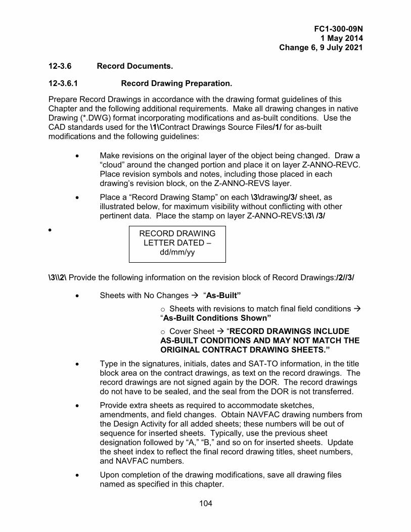
FC1-300-09N 1 May 2014
Change 6, 9 July 2021
104
Record Documents.
12-3.6.1 Record Drawing Preparation.
Prepare Record Drawings in accordance with the drawing format guidelines of this Chapter and the following additional requirements. Make all drawing changes in native Drawing (*.DWG) format incorporating modifications and as-built conditions. Use the CAD standards used for the \1\Contract Drawings Source Files/1/ for as-built modifications and the following guidelines:
• Make revisions on the original layer of the object being changed. Draw a “cloud” around the changed portion and place it on layer Z-ANNO-REVC. Place revision symbols and notes, including those placed in each drawing’s revision block, on the Z-ANNO-REVS layer.
• Place a “Record Drawing Stamp” on each \3\drawing/3/ sheet, as illustrated below, for maximum visibility without conflicting with other pertinent data. Place the stamp on layer Z-ANNO-REVS:\3\ /3/
•
\3\\2\ Provide the following information on the revision block of Record Drawings:/2//3/
• Sheets with No Changes “As-Built” o Sheets with revisions to match final field conditions “As-Built Conditions Shown” o Cover Sheet “RECORD DRAWINGS INCLUDE AS-BUILT CONDITIONS AND MAY NOT MATCH THE ORIGINAL CONTRACT DRAWING SHEETS.”
• Type in the signatures, initials, dates and SAT-TO information, in the title block area on the contract drawings, as text on the record drawings. The record drawings are not signed again by the DOR. The record drawings do not have to be sealed, and the seal from the DOR is not transferred.
• Provide extra sheets as required to accommodate sketches, amendments, and field changes. Obtain NAVFAC drawing numbers from the Design Activity for all added sheets; these numbers will be out of sequence for inserted sheets. Typically, use the previous sheet designation followed by “A,” “B,” and so on for inserted sheets. Update the sheet index to reflect the final record drawing titles, sheet numbers, and NAVFAC numbers.
• Upon completion of the drawing modifications, save all drawing files named as specified in this chapter.
RECORD DRAWING LETTER DATED –
dd/mm/yy
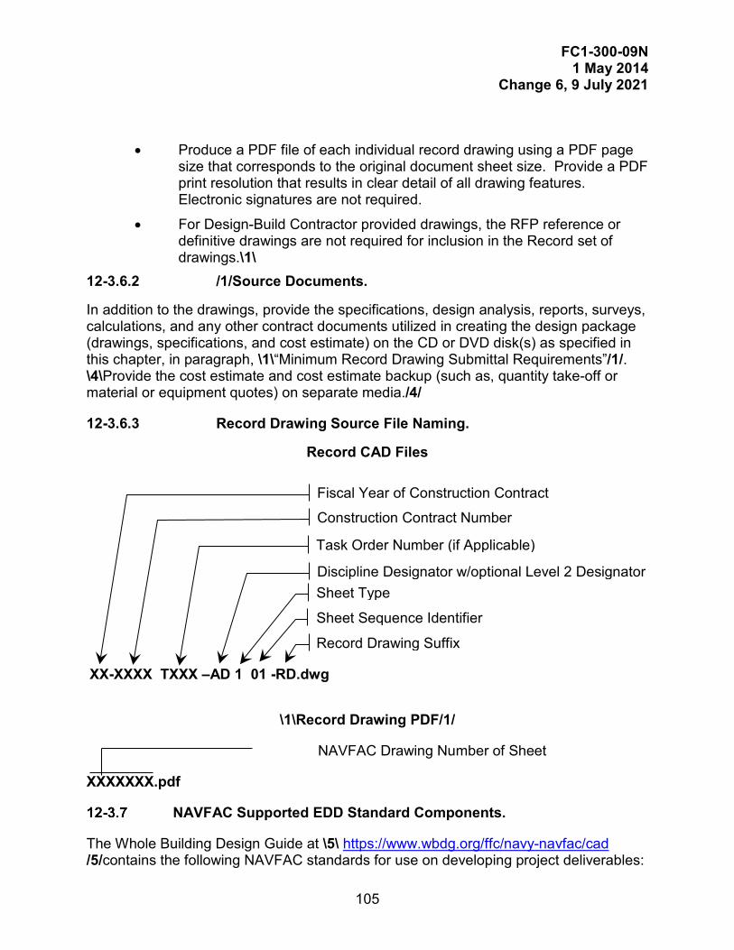
FC1-300-09N 1 May 2014
Change 6, 9 July 2021
105
• Produce a PDF file of each individual record drawing using a PDF page size that corresponds to the original document sheet size. Provide a PDF print resolution that results in clear detail of all drawing features. Electronic signatures are not required.
• For Design-Build Contractor provided drawings, the RFP reference or definitive drawings are not required for inclusion in the Record set of drawings.\1\
12-3.6.2 /1/Source Documents.
In addition to the drawings, provide the specifications, design analysis, reports, surveys, calculations, and any other contract documents utilized in creating the design package (drawings, specifications, and cost estimate) on the CD or DVD disk(s) as specified in this chapter, in paragraph, \1\“Minimum Record Drawing Submittal Requirements”/1/. \4\Provide the cost estimate and cost estimate backup (such as, quantity take-off or material or equipment quotes) on separate media./4/
12-3.6.3 Record Drawing Source File Naming.
Record CAD Files
\1\Record Drawing PDF/1/
NAVFAC Drawing Number of Sheet
XXXXXXX.pdf
NAVFAC Supported EDD Standard Components.
The Whole Building Design Guide at \5\ https://www.wbdg.org/ffc/navy-navfac/cad /5/contains the following NAVFAC standards for use on developing project deliverables:
XX-XXXX TXXX –AD 1 01 -RD.dwg
Fiscal Year of Construction Contract
Construction Contract Number
Task Order Number (if Applicable)
Discipline Designator w/optional Level 2 Designator Sheet Type
Sheet Sequence Identifier
Record Drawing Suffix

FC1-300-09N 1 May 2014
Change 6, 9 July 2021
106
NAVFAC Standard CAD title blocks (border sheets), pen configuration tables, NCS templates, layer keys, and standard details.
NAVFAC ELECTRONIC SIGNATURE REQUIREMENTS.
Federal legislation has established the legality and acceptability of electronic signatures (\2\in accordance with /2/Public Law 106-229, Electronic Signatures in Global and National Commerce Act). NAVFAC requires the use of electronic signatures for the certification of all drawings and specifications. The following sections outline the requirements for electronic signatures on NAVFAC deliverables.
General Requirements.
\3\Prior to final NAVFAC signature, the following steps must be completed:
• Government Project Manager receives SATISFACTORY TO (SAT-TO) from the Client
• Type “Approved By [Name of Client Representative] via [media (such as email or fax)]” in the ACTIVITY field, and the date the SAT TO was received, in the DATE field. SAT TO must appear on every drawing sheet.
• In the “exception” field, if project requires Client signature for this field, the Client must sign the package using Sign-It®./2/
• Type in the initials of the “DES, DRW, and CHK” areas on the border to indicate the individual(s) who designed, drafted, and checked the sheet, respectively. These areas must display the responsible individual’s initials in CAD text. The \3\CHK/3/ initials CANNOT be the same as the DES and DRW initials.
• The “\2\PM/DM,/2/ BRANCH MANAGER, CHIEF ENG/ARCH, and FIRE PROTECTION” fields are for use by NAVFAC only and may be either signed with Sign-it® or initialed with CAD text. If signed, the individual signing is a supervisor or has delegated signature authority under NAVFACINST 5216.1L. \1\\2\Individual NAVFAC activities may assign the use of the CHIEF ENG/ARCH field (such as to the Integrated Product Team Lead);/2/ clear the CAD text if not used. A signature block is shown in Figure 12-3./1/
• Electronically sign the PDF of the specification coversheet (RFP coversheet for DB \2\RFP Preparer/2/) and seal and sign each drawing PDF sheet, using Sign-it®. If the professional is required to submit “wet-signed” documents to be in compliance with their state regulations, then a separate “wet-signed” drawing and specification set may be submitted, meeting the requirements of paragraph “Wet-Signed Documents”. A fully electronic solicitation, including electronic signatures is still required.

FC1-300-09N 1 May 2014
Change 6, 9 July 2021
107
When the above steps are completed, NAVFAC will sign the “For Commander NAVFAC”\2\ in the title block on \2\each Drawing and on the coversheet of the Specifications/2/. This is required on final designs including designs prepared under Design-Build contracts./3/
\1\Figure 12-3/1/ NAVFAC Signatures
Specific Software Requirements.
\1\Sign design documents/1/ using the Sign-it® software. Current version information, points of contact, and order forms for Sign-it® are located on the WBDG \5\(https://www.wbdg.org/ffc/navy-navfac/cad)/5/.
Wet-Signed Documents.
\2\DC4, DC BLTL, PMEB or Design Director/2/ SignIT Signature and Date
Client/Customer\2\ Typed “Approved by [Client’s name] via [media]”, and date SAT-TO received/2/
DES – DRW – REV Typed Initials
PM/DM \1\Typed Initials/1/
BRANCH MANAGER \2\Typed Initials or /2/SignIT Signature
CHIEF ENG/ARCH \2\Typed Initials (if designated by NAVFAC Activity), or clear CAD text/2/
FIRE PROTECTION \2\Typed Initials or /2/SignIT Signature
\3\CHK/3/
\3\CHK/3/
FC1-300-09N 1 May 2014
Change 6, 9 July 2021
108
If required, produce any wet-signed documents from the final electronic PDF documents (prior to electronic signature application) submitted to NAVFAC.\2\/2/\1\
BUILDING INFORMATION MANAGEMENT/MODELING (BIM) REQUIREMENTS.
For \3\projects that require BIM/3/, comply with requirements for Drawings and as follows.
BIM Definitions.
12-5.1.1 BIM Project Execution Plan (PxP).
The DOR is responsible for the PxP, which is a mandatory document that identifies \2\in detail: key contacts, quality control, software used, model organization, and project deliverables when designing with a BIM application/2/.
Download the PxP file found on the NAVFAC BIM Page of the Whole Building Design Guide website (http://www.wbdg.org/bim/navfac_bim.php).
12-5.1.2 3D Parametric Modeling Application.
A software application which uses select criteria, parameters and variables to determine the characteristics (\3\including/3/ length, width, height) of a Model Element and defines relationships between other model elements.
12-5.1.3 Model.
A digital representation of the physical and functional characteristics of a facility or a part thereof, comprised of Model Elements with Element Data.
12-5.1.4 Model Element.
A self-contained object within a Model with a unique identification, whose behavior and properties are defined by data fields (Element Data). Model Elements can represent a physical entity, such as a pump or a concrete wall, and range from the simple (a standalone pump) to the complex (a multi-component wall system).
12-5.1.5 Element Data.
The non-graphical information of a Model Element that defines the various characteristics of the object. Element Data can include properties such as parametric values that drive physical sizes (length, width, height), material definitions and characteristics ( wood, metal), manufacturer data, industry standards (AISC steel properties), and project identification numbers. The required Element Data fields can be found in the Required Facility Asset Fields of the Model & Facility Data Matrix tab in the \2\eOMSI FDW/2/.
12-5.1.6 Design Model.
FC1-300-09N 1 May 2014
Change 6, 9 July 2021
109
The Model created and delivered by the DOR which is developed to a specific Level of Detail (LOD) as defined in the Model & Facility Data Matrix tab of the \2\eOMSI FDW/2/.
12-5.1.7 Record Model.
The Design Model modified by the KTR which incorporates the real world conditions of the facility as constructed.
12-5.1.8 Facility Data Workbook.
The Facility Data Workbook (FDW) defines the BIM Levels of Detail (LOD) required for each system, during design. The FDW is initially populated during design, and completed during construction with the actual components and systems provided. The FDW is provided as part of UFGS 01 78 24.00 20, and required in accordance with paragraph 7-2.
Minimum Modeling and Data Requirements.
12-5.2.1 General.
Use 3D Parametric Modeling Application(s) to develop the Design Model(s) based on the project scope.
12-5.2.2 Model & Facility Data Matrix.
DOR completes the Model & Facility Data Matrix tab of the \2\eOMSI/2/ FDW (XLS) utilizing the Instructions tab found in \2\the eOMSI/2/ FDW. Download the \2\eOMSI/2/ FDW from the NAVFAC BIM Page of the Whole Building Design Guide.\2\/2/
12-5.2.3 Model Files.
Produce an independent Design Model for each discipline that can be linked to each other. Document the Model names and Model links in the PxP.
12-5.2.4 Element Data.
Use the Required Facility Asset Fields (Element Data) specified in the Model & Facility Data Matrix tab of the \2\eOMSI/2/ FDW for all modeled elements.
12-5.2.5 Room Space Data.
Include room space data defining net square footage and net volume to develop the room finish schedule including room names and numbers.
12-5.2.6 Schedules.
Produce Schedules (Finish, Room, Lighting\2\, Plumbing, Equipment, Openings/2/) from the Model Elements and Element Data within the Model.
Design Model.

FC1-300-09N 1 May 2014
Change 6, 9 July 2021
110
DOR develops the Design Model using a 3D Parametric Modeling Application \2\/2/to produce a complete set of \2\Contract Drawings/2/. All submittals must be compatible and editable using their native software as defined in the PxP.

FC1-300-09N 1 May 2014
Change 6, 9 July 2021
111
12-5.3.1 Design Model Naming Convention.
Refer to Table 12-1 for the Facility Type and Facility I.D. Designators.
Use the following naming convention for all BIM Design Models files:
Record Model.
KTR develops the Record Model by modifying the DOR’s Design Model as the facility is being constructed. Utilize the Record Model Grade specified in the Model & Facility Data Matrix tab in the\2\ eOMSI/2/ FDW.
12-5.4.1 Record Model Naming Convention.
12-5.4.2
XXXX XXXX-#######-A.xxx
Facility Type Designator
Facility I.D. Designator (four characters)
Job Number (eProjects Work Order No.)
Discipline Designator
File Extension (defined in \2\eOMSI FDW Instructions Tab/2/)
XX XXXX TXXX-A-RM.xxx
Fiscal Year of Construction
Construction Contract Number
Task Order Number (if Applicable)
Discipline Designator
File Extension (defined in \2\eOMSI FDW Instructions Tab/2/)
Record Model suffix w/ Optional Level 2 Design
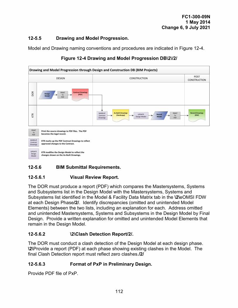
FC1-300-09N 1 May 2014
Change 6, 9 July 2021
112
Drawing and Model Progression.
Model and Drawing naming conventions and procedures are indicated in Figure 12-4.
Figure 12-4 Drawing and Model Progression DB\2\/2/
Drawing and Model Progression through Design and Construction DB (BIM Projects)
KTR
DOR
POST CONSTRUCTIONDESIGN CONSTRUCTION
Design Model
Contract Drawings(PDF)
As-Built Drawings(Hardcopy)
Record Drawings(PDF)UPDATE
Design ModelRecord Model
PRINTTo
MARKUPContract Drawings
PRINTTo
PRINTTo
Print the source drawings to PDF files. The PDF becomes the legal record.
MARKUPContract Drawings
KTR marks up the PDF Contract Drawings to reflect approved changes to the Contract.
KTR modifies the Design Model to reflect the changes shown on the As-Built Drawings.
UPDATEDesign Model
BIM Submittal Requirements.
12-5.6.1 Visual Review Report.
The DOR must produce a report (PDF) which compares the Mastersystems, Systems and Subsystems list in the Design Model with the Mastersystems, Systems and Subsystems list identified in the Model & Facility Data Matrix tab in the \2\eOMSI FDW at each Design Phase/2/. Identify discrepancies (omitted and unintended Model Elements) between the two lists, including an explanation for each. Address omitted and unintended Mastersystems, Systems and Subsystems in the Design Model by Final Design. Provide a written explanation for omitted and unintended Model Elements that remain in the Design Model.
12-5.6.2 \2\Clash Detection Report/2/.
The DOR must conduct a clash detection of the Design Model at each design phase. \2\Provide a report (PDF) at each phase showing existing clashes in the Model. The final Clash Detection report must reflect zero clashes./2/
12-5.6.3 Format of PxP in Preliminary Design.
Provide PDF file of PxP.
FC1-300-09N 1 May 2014
Change 6, 9 July 2021
113
12-5.6.4 Format of Final Design Model.
Provide the final Design Model in native format and exported CAD files in DWG format.
12-5.6.5 Format of Final Record Model.
Provide the final Record Model in native format and exported CAD files in DWG format./1/
12-5.6.6 Facility Data Workbook (FDW).
Provide the Facility Data Workbook in Excel format.
EDD MEDIA AND ORGANIZATION.
General.
Provide Official submittals on CD or DVD Discs or as directed. Submit all CAD files in native Drawing (*.DWG) format in the NAVFAC supported version. Drawing files must be uncompressed and unzipped. Purge files of all unused items (blocks, layers, line types, and nested items). Do not submit single drawing files with multiple layouts except as described in the paragraph in this chapter entitled, “NAVFAC Standard Drawing Format.” Do not bind cross referenced parent and child drawings. If the submitted native DWG files are not the native file format for the authoring software, provide all native design data in the original authored format in addition to the native DWG compliant format.
Minimum Final Submittal Requirements.
Provide the following as a minimum at final design submittal. NAVFAC Components may require additional submittals, CD/DVDs, and numbers of copies.
CD/DVD#1 - Final Design or RFP for Government Signature (2 Copies)
Drawing PDF file(s) electronically signed by the Professional(s) in Responsible Charge
RFP or Specification PDF file electronically signed by the Professional in responsible charge in the “Submitted By:” Section
CD/DVD #2 - Source Files (2 Copies)
/CAD All Native CAD Files for all disciplines; include all X-refs, image, or other external reference files.\1\
/BIM (for BIM projects only) All native BIM models, PxP, Visual Review Report\2\, and Clash Detection Report./2/
/eOMSI FDW/1/

FC1-300-09N 1 May 2014
Change 6, 9 July 2021
114
/Specifications folder - All Specification source files
/PullData folder (-.sec files)
/RFP folder - All source files of RFP package, further divided by subfolders into Parts, except for specification section files or CAD files.
/Calculations folder (pdf and input/source files)
/Support folder
/Reports-Surveys- Studies folder
/Basis of Design folder
/Architectural Color Boards folder (photos)
/Other folder \3\(such as/3/Photos, Project background/support files)
CD/DVD#3 - Cost Data (1 copy)
Minimum Record Drawing Submittal Requirements.
Submit Four CD/DVDs. Each must have the following folders and content.
/Record Drawings/
/CAD - All record CAD files and X-refs for all disciplines must be stored in the same folder (directory). /PDF
/Specs
/Calcs
/Cost
/Basis of Design
/Other
\4\
FC1-300-09N 1 May 2014
Change 6, 9 July 2021
115
PHASE: PRELIMINARY DESIGN: MCON
GENERAL REQUIREMENTS.
Preliminary Design for the Department of the Navy, Military Construction (MCON) requires development of Preliminary Design Deliverables to ensure that projects submitted for Congressional and Presidential approval contain sufficient planning, accurate scope, adequate documentation, and a valid cost estimate for successful execution. Preliminary Design begins with the issuance of Preliminary Design Authorization (PDA).
PRELIMINARY DESIGN.
Preliminary Design Authority \6\/6/ authorizes development of Preliminary Design Deliverables including a budget-ready DD Form 1391 for submission into the Department of Navy’s (DoN) Military Construction budget, through the facility programming process. The purpose of PDA is to validate planning requirements and develop Preliminary Design Deliverables and cost estimate for MCON projects. Upon receipt of PDA, Preliminary Design Deliverables and a cost estimate are prepared to ensure MCON projects submitted for Congressional and Presidential approval contain sufficient planning, accurate scope, a minimum set of design deliverables, and a cost estimate for successful contract award and execution.
Preliminary Design Deliverables as described in this chapter do not have the same level of detail as the Schematic Design Submittal described in Chapter 14. Although many of the same requirements are contained in both submittals, they are developed for different purposes.
INSTALLATION/PWD DD FORM 1391 ASSESSMENT.
Conduct an assessment of the existing project documentation, including the Installation/PWD DD Form 1391, developed during the planning phase by Asset Management. \6\
PDA DOCUMENTATION.
The project documentation establishes the basic requirements needed to meet the mission of the Support Command.
PDA Element.
Elements of the project documentation for most facility projects include: a DD Form 1391 in Electronic Project Generator (EPG) format with detailed scope, collateral equipment list with cost, and preliminary budgetary cost information for primary facility and supporting facilities (for example, utilities, connections, and site work). PDA will only be issued once the Installation/PWD DD Form 1391 sufficiently addresses the following elements:
FC1-300-09N 1 May 2014
Change 6, 9 July 2021
116
• Site Identification & Approval
• Economic Analysis
• Facility Planning Data o Basic Facility Requirement (BFR) o Functional Planning Document (FPD) o Requirement Study (for example, utility, traffic, asbestos, lead, radon, AT/FP)/6/
• Equipment List and Cost
• Project Cost
• Environmental, Historic, Cultural Resources Impacts
• Project Requirements Schedule, and Engineering Studies (Utilities, Geotechnical, Site, Structural, and Hazardous Materials Investigations)\6\
PDA File Naming Convention.
Use the file naming convention shown in Figure 13-1 for PDA files and Element Extensions provided in Table 13-1.
In exception, file naming conventions for the Cost and Schedule Risk Analysis (CSRA) and Design Construction Agent (DCA) are as shown in Table 2 where FYXX is the fiscal year of the Project and PXXX is the Project’s P-number. The submittal name is either RegFEC_Team_Final, Program_Final, or Certified_Final.
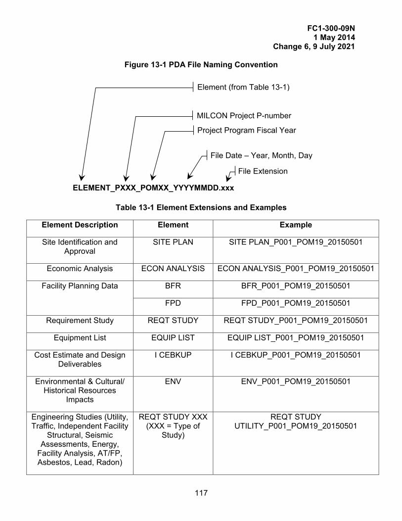
FC1-300-09N 1 May 2014
Change 6, 9 July 2021
117
Figure 13-1 PDA File Naming Convention
Table 13-1 Element Extensions and Examples
Element Description Element Example
Site Identification and Approval
SITE PLAN SITE PLAN_P001_POM19_20150501
Economic Analysis ECON ANALYSIS ECON ANALYSIS_P001_POM19_20150501
Facility Planning Data BFR BFR_P001_POM19_20150501
FPD FPD_P001_POM19_20150501
Requirement Study REQT STUDY REQT STUDY_P001_POM19_20150501
Equipment List EQUIP LIST EQUIP LIST_P001_POM19_20150501
Cost Estimate and Design Deliverables
I CEBKUP I CEBKUP_P001_POM19_20150501
Environmental & Cultural/ Historical Resources
Impacts
ENV ENV_P001_POM19_20150501
Engineering Studies (Utility, Traffic, Independent Facility
Structural, Seismic Assessments, Energy,
Facility Analysis, AT/FP, Asbestos, Lead, Radon)
REQT STUDY XXX (XXX = Type of
Study)
REQT STUDY UTILITY_P001_POM19_20150501
ELEMENT_PXXX_POMXX_YYYYMMDD.xxx
Element (from Table 13-1)
MILCON Project P-number
Project Program Fiscal Year
File Date – Year, Month, Day
File Extension
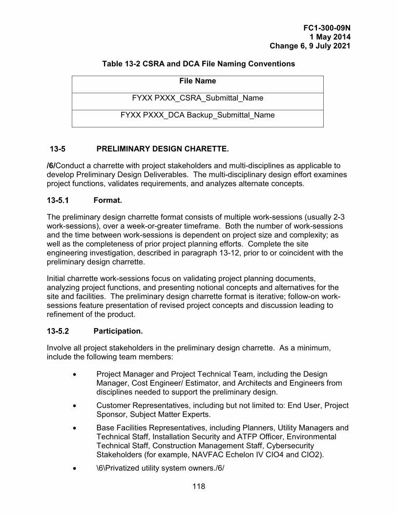
FC1-300-09N 1 May 2014
Change 6, 9 July 2021
118
Table 13-2 CSRA and DCA File Naming Conventions
File Name
FYXX PXXX_CSRA_Submittal_Name
FYXX PXXX_DCA Backup_Submittal_Name
PRELIMINARY DESIGN CHARETTE.
/6/Conduct a charrette with project stakeholders and multi-disciplines as applicable to develop Preliminary Design Deliverables. The multi-disciplinary design effort examines project functions, validates requirements, and analyzes alternate concepts.
Format.
The preliminary design charrette format consists of multiple work-sessions (usually 2-3 work-sessions), over a week-or-greater timeframe. Both the number of work-sessions and the time between work-sessions is dependent on project size and complexity; as well as the completeness of prior project planning efforts. Complete the site engineering investigation, described in paragraph 13-12, prior to or coincident with the preliminary design charrette.
Initial charrette work-sessions focus on validating project planning documents, analyzing project functions, and presenting notional concepts and alternatives for the site and facilities. The preliminary design charrette format is iterative; follow-on work-sessions feature presentation of revised project concepts and discussion leading to refinement of the product.
Participation.
Involve all project stakeholders in the preliminary design charrette. As a minimum, include the following team members:
• Project Manager and Project Technical Team, including the Design Manager, Cost Engineer/ Estimator, and Architects and Engineers from disciplines needed to support the preliminary design.
• Customer Representatives, including but not limited to: End User, Project Sponsor, Subject Matter Experts.
• Base Facilities Representatives, including Planners, Utility Managers and Technical Staff, Installation Security and ATFP Officer, Environmental Technical Staff, Construction Management Staff, Cybersecurity Stakeholders (for example, NAVFAC Echelon IV CIO4 and CIO2).
• \6\Privatized utility system owners./6/
FC1-300-09N 1 May 2014
Change 6, 9 July 2021
119
IDENTIFICATION OF UNIQUE PROJECT REQUIREMENTS.
Identify and coordinate unique project requirements during the preliminary design charrette. Coordinate costing and development of unique requirements identified by the Project Technical Team, or other appropriate personnel, of issues not related to design. Unique requirements that are prone to be overlooked include:
• Construction restrictions due to airfield/waterfront operations
• Explosive Safety Site Approval
• Temporary facility requirements
• Laydown areas which may include offsite areas that increase project cost, such as batch plants for large pavement projects and stockpiling area for contaminated material
• Construction phasing requirements
• Locating property lines and other land restrictions, such as easements
• Security and Anti-terrorism requirements (SCIF/SAPT)
• Environmental issues, including hazardous material abatement, radon mitigation, permitting, and NEPA
• Cost of disposing hazardous materials
• Seismic, fire protection and sustainability triggers for renovation projects
• Host Nation Requirements (for overseas projects; for example, verify if energy or renewable requirements)
• \6\On Installations with privatized utilities (such as gas, water, electric), coordination with the Privatized utility system owners for utility system connections and upgrades to the utility system. Utilities cannot be disturbed without the written consent of the privatized utility owner. Ensure utility system costs are included in the DD Form 1391./6/
DD FORM 1391.
Prepare the project’s DD Form 1391 documentation for submission in the Electronic Project Generator (EPG). Conform to the following, latest guidance provided by the Government Project Manager
• Consistency Review Board (CRB) Guidelines & DD Form 1391 Development
• Budget Quality DD Form 1391 Editing and Style Guidelines
• POM PDA Guidance for applicable MILCON Program Budget Year

FC1-300-09N 1 May 2014
Change 6, 9 July 2021
120
ROLES AND RESPONSIBILITIES.
DD Form 1391 documentation is the combined result of a team project development effort from planning through engineering design. DD Form 1391 content is divided into blocks. Some blocks cover Designer or Project Manager prepared information, while other blocks are dedicated to Planning data. Responsible entities for DD Form 1391 content are as follows:
• Block 9, Cost Estimates: Project Team
• Block 10, Description of Proposed Construction: Project Team
• Block 11, Requirement: Government Planner and Activity/Region
• Block 12, Supplemental Data: Government Planner
• Block 12, Budget Estimate Summary Sheet: Project Team
• Block 12, Estimated Design Data: Project Manager
• Block 12, Equipment from Other Appropriations: Project Manager and Government Activity/Region
PRELIMINARY PROJECT NARRATIVE.
The project narrative, along with the drawings, documents the preliminary project design that facilitates the budget-ready project cost development. Preliminary design is driven by the requirements identified by Project Stakeholders, Government Project Planners, and applicable design criteria. The preliminary design is not constrained by a pre-determined budget.
Identify the following in the project narrative document:
Description of Proposed Construction.
Revise and enhance Block 10 statements in the prior DD Form 1391 that was prepared during planning. Prepare description of proposed construction in compliance with Block 10 requirements in “CRB Guidelines & DD Form 1391 Development” and “Budget Quality DD Form 1391 Editing and Style Guidelines.” Use verbiage prepared for this portion of the Project Program for Block 10 of the budget-ready DD Form 1391.
Project Objectives.
Identify the Mission Statement and Facility Function. Describe issues that need to be considered in future project development, including, but not limited to: Project Specific Priorities, Workflow Processes, Appropriate Design, Special Design Challenges, Adaptability and Flexibility, and target dates for Initial and Full Operating Capability (IOC/FOC).
Site Analysis.

FC1-300-09N 1 May 2014
Change 6, 9 July 2021
121
Define existing site conditions and site development requirements. Identify constraints that restrict development. Project cost can increase for sites that are developable, but constrained – and require special considerations to build on the site. Describe situations where the site location is associated with other-agency or Command approval processes (for example, NOSSA, SHPO, NEPA, NAVAIR). Refer to Paragraph 13-12 for Site Engineering Investigation.
Building Requirements.
Develop the facility space planning concept. Describe primary blocks, such as, interior spatial areas, work flow/processes, functional relationships, circulation patterns, equipment/storage requirements, and security issues. Schematically tabulate facility floor area requirements on a room-by-room basis. Verify that floor plan area requirements identified by the functional analysis match Basic Facilities Requirement (BFR) documents, prepared by Government project planners.
Host Nation Requirements.
For OCONUS projects, identify host-nation requirements, such as energy or renewable requirements or others.
DISCIPLINE-SPECIFIC BASIS OF DESIGN.
Develop separate and condensed summaries for core disciplines (in reference to the Core UFCs defined in UFC 1-200-01) including: Geotechnical, Civil, Landscape Architecture, Architectural, Structural, Fire Protection, Mechanical, and Electrical.
Provide sufficient definition in the discipline-specific Basis of Design to support the development of a cost estimate for that discipline.
Building Systems.
For the building systems (such as architecture, structural, mechanical, electrical, fire protection), identify the discipline-specific design assumptions, as required to support a parametric estimate on the Primary Facility. Consult with interior design personnel for select projects, where unique interior design requirements cannot be captured by standard parametric estimating techniques for the facility-type. Ensure that risks associated with facility systems identified, typically on the Preliminary Hazard List (PHL) or Preliminary Hazard Analysis (PHA) if developed prior to the PDA, are mitigated or have engineering controls to eliminate the risk.
Site.
For the site, including utility systems (for example, civil, electrical, telecommunication) identify the design assumptions for Supporting Facilities, as required to support quantities and unit costs. Consult with landscape architecture personnel for select
FC1-300-09N 1 May 2014
Change 6, 9 July 2021
122
projects, where a portion of total costs may be associated with landscape architectural requirements.
Cybersecurity Impact Level.
Indicate the Cybersecurity Impact Level for the control systems. Provide project-specific requirements.
Ratio of Renovation Cost to Replacement Cost.
For renovation projects, provide an analysis of the ratio of renovation cost to replacement cost \5\(see UFC 3-701-01 for the definition of replacement cost)/5/. Clearly identify ratios that trigger additional facility upgrades (such as ATFP, seismic evaluation and retrofit, and sustainability). Re-address the costs in the Economic Analysis provided from the Project Readiness Index (PRI) #1 development phase.
Narratives.
In addition to basis of design narratives for core disciplines, provide separate narratives for the following cross-disciplinary elements. Devote special attention to issues that may have significant impact such as:
• ATFP – Discuss the applicability of ITG 2018-02 with the customer, and identify ATFP requirements that have significant cost impact including full compliance with UFC 4-010-01 and progressive collapse avoidance.
• Sustainability – Indicate the feasibility of meeting Guiding Principle requirements and other sustainability goals for the project in accordance with UFC 1-200-02. Include a draft NAVFAC High Performance Sustainable Building (HPSB) Checklist. Where Third Party Certification (TPC) is an anticipated requirement, develop a draft TPC checklist. \6\Discuss the scope for commissioning, to include systems to be commissioned, development of required documents, and Commissioning Provider contracting method. /6/
PRELIMINARY DRAWINGS.
Prepare preliminary design drawings or sketches, for the purpose of:
1) Clearly illustrating the basic project scope to stakeholders, and
2) Supporting development of the parametric cost estimate.
Preliminary design drawings or sketches need not feature the level-of-detail or format specified in Chapter 7; especially where highly complex drawings could detract from the primary intent. Include the following:
FC1-300-09N 1 May 2014
Change 6, 9 July 2021
123
• Vicinity Map and Location Plan
• Demolition Plan: Show facilities to be demolished (if required).
• Site Plan(s): o Show the layout (size and possible shape) of the new facility in relation to major landmarks. o Show the possible location of access roads, parking, landscaping, pedestrian walkways, plazas and patios, landscape structures, roads, and sidewalks, as applicable. o Indicate approximate dimensions and orientation. o Clearly indicate any site constraints such as explosive safety arcs, flood zones, wetlands or other environmentally sensitive areas. o Where Anti-Terrorism/Force Protection (ATFP) is applicable, clearly depict setback distances to vulnerabilities, including parking, roadways, and obstructions. \4\ o Provide a Building Code site plan showing the assumed property lines of adjacent structures./4/
• Utilities Plans: o Show utility lines and their points of connection in relation to existing adjacent structures, roads, and utilities. o Show off-site utility upgrade requirements needed to support the project. o Show civil, mechanical, electrical and telecommunication utilities to clearly convey the scope and quantities associated with various utility improvements. o On large utility distribution projects, provide one-line diagrams of electrical and telecommunication utilities. o Show mechanical building utilities coming into the building (for example, water, sanitary sewer, gas piping, and steam.
• Building Floor Plans: o Provide floor plans depicting functional utilization of spaces. \5\Incorporate Collateral Equipment (CEQ) and Furniture, Fixtures and Equipment (FF&E) into the

FC1-300-09N 1 May 2014
Change 6, 9 July 2021
124
design development and indicate on building floor plan(s)./5/ o For renovation projects, provide separate drawings to identify existing conditions, demolition, and new construction elements. o Provide mechanical and plumbing floor plans to include utilities coming into the building (for example, water, sanitary sewer, gas piping, and steam), and major pieces of equipment with clearances (for example, water, heater/storage tank, HVAC equipment, and pumps).
• Building Elevations: Provide elevations that depict the building character, and indicate materials.
COST ESTIMATE.
Cost estimate class requirements are a minimum Class 4 and a desired Class 3 in accordance with AACE RP 56R-08. NAVFAC Headquarters may issue project specific guidance at PDA. Cost estimate methodology and cost tools are addressed in \5\Chapter 9./5/
Project definition deliverables are required to be commensurate with the required estimate class. Refer to Appendix D, Table D-1 for class-specific project definition deliverables requirements. Appendix D, Table D-2 is the minimum requirement for PDA.
SITE ENGINEERING INVESTIGATION (SEI).
Supplement known site information/studies and examine high risk cost elements by conducting on-site utility investigation and site engineering studies to include soil borings and analysis, topographic analysis, fire flow tests and flood projections & mitigation studies.
Evaluate if site information obtained as part of the preliminary design effort is sufficient to proceed with the full-design of the proposed facility. If sufficient data is not available, provide a list of additional site investigation needed to proceed with design.
Utility Investigation.
Locate and identify the nearest points of connection for all utilities. If the points of connection are outside the project boundaries, provide additional information that shows the locations.
• Verify Installation/PWD DD Form 1391 identified point of connection.
FC1-300-09N 1 May 2014
Change 6, 9 July 2021
125
• Retrieve and review the Installation’s utility plans and consult with Government utilities personnel\6\; where utility systems are privatized, consult with privatized utility system owner./6/
• Validate adequate utility capacities at points of connection.
• \6\For Government-owned utility systems, conduct waterflow testing in accordance with UFC 3-600-01; for privatized utility systems, request waterflow testing data from privatized utility system owner./6/
• For utilities projects: Retrieve and review the utility study that supports the scope and type of work to be performed.
Subsurface/Geotechnical Investigations.
Consult with a Geotechnical Engineer to determine if the site can be characterized and foundation systems conceptualized based on known geologic conditions. If known geologic data can be used, the Geotechnical Engineer must document in the Basis of Design that the conceptual design for pavement and foundation design is based upon available soils information
If existing geological data is not sufficient and for large projects with anticipated Special Foundation costs (for example, pile foundations, mat foundations, significant grading and over-excavation, ground improvement), conduct a full soils investigation at the preliminary design stage. Perform foundation and soils investigations, including sampling, testing, and evaluation, with requirements set forth in Chapter 4. If ground source heat pumps are being considered, determine the soil characteristics for the geothermal well field.
Topographic Survey.
Utilize existing topographic data to the maximum extent possible.
For projects where costs associated with grading and dredging are significant conduct topographic surveys at the preliminary design stage. Conduct topographic surveys in accordance with Chapter 4. Topographic Surveys must indicate significant site elements, including, but not limited to, utility points of connection, natural resource boundaries, fish and wildlife habitats (including buffer zones), rookeries, wetlands, and other environmentally sensitive areas.
Existing Building Surveys.
For repair, renovation, or rehabilitation projects, perform engineering studies to assess extent of the work, and to provide budget-level costs. These studies include, but are not limited to, structural, electrical, mechanical, fire protection, ATFP, building envelope, accessibility, and roof systems and components.
When triggered, conduct Tier I or Tier II seismic evaluations in accordance with UFC 3-310-04 and identify mitigation costs. Defer Tier III investigations until subsequent

FC1-300-09N 1 May 2014
Change 6, 9 July 2021
126
design phases (Final Solicitation Document Design Authority, FSDDA). For renovations of historic properties: Coordinate with the NAVFAC Environmental Cultural Resources Office to determine special construction elements and other project constraints. For fire protection requirements, refer to the paragraphs titled “Planning” and “Existing Facilities” in UFC 3-600-01.
Hazardous Materials Investigation.
Validate and address findings from Field Investigation Report conducted during planning prior to PDA, and conducted in accordance with UFC 3-810-01N. Hazardous Materials, along with their associated costs, must be identified and addressed in the DD1391. MCON Design (P&D) Appropriations may only be used for comprehensive investigations hazardous materials investigations that are directly in support of a project design solution. For example, investigations that directly support development of design drawings and specifications.
13-13.5.1 Survey and Research.
As a minimum, for budget-ready costs, conduct a visual survey of existing field conditions. Consult with Government Environmental personnel, and research records for existing hazardous materials documentation and known site contamination issues. Determine if the site is part of an installation restoration program/project. Base the preliminary design on conservative assumptions from the visual survey and records search.
13-13.5.2 Demolition, Renovation, Repair, or Contaminated Sites.
For projects that include significant demolition, renovation, or repair, or sites with significant known environmental contamination issues, verify the presence of hazardous materials such as, but not limited to, asbestos, RCRA 8 metals (arsenic, barium, cadmium, chromium, lead, mercury, selenium and silver), PCB, and mercury. For specific requirements, comply with UFC 3-810-01N.
Building Code Assessment of Adjacent Structures.
When the proposed construction is within 60-ft (18.3-m) of existing adjacent structures, conduct a building code assessment of the adjacent structures. Information about adjacent structures must include; construction type, fire resistive rating of exterior walls, wall openings, number of floors, area per floor, total building area, occupancy classification, and if the building is fully protected with an automatic fire sprinkler system. The purpose of obtaining this information is to assure the new building (or addition) does not encroach on minimum separation requirements or assumed property line based on the design assumptions and building code analysis of the existing building(s).
CALCULATIONS.
Plumbing.
FC1-300-09N 1 May 2014
Change 6, 9 July 2021
127
Provide the following plumbing calculations:
• Domestic water size coming into the building (looking for a preliminary calculation on the water size. Needed to determine if the existing water main has the size/capacity for demand).
• Available Water pressure (If the water pressure is suspect, a water pressure calculation is needed to determine if domestic water pump is required).
• Water Heater Size/Storage (preliminary calculation on the water heater/storage tank size).
• Sanitary sewer size coming into the building (preliminary calculation on the sanitary sewer size to determine if the existing main has the size/capacity for demand).
• Sanitary Sewer piping elevation/slope (preliminary calculation to determine if a grinder pump is required).
• Building Utilities (such as Steam and Gas) (preliminary calculation on the utility size to determine if the existing main has the size/capacity for demand).
• Sustainability (such as solar hot water or rainwater harvesting).
• Preliminary calculations and LCCE as needed to support position. Mechanical.
• Building Cooling Load (Block Cooling Load Calculation)
• Building Heating Load (Block Heating Load Calculation)
• ASHRAE 62 Calculation (preliminary Calculation needed for DOAS
• systems).
• Preliminary Equipment Sizes (with clearances to size mechanical rooms if required).
• Life Cycle Cost Analysis (LCCA ) (Performed on the mechanical systems such that a single system is selected during PDA.)
• Commissioning/Acceptance (determine if required for cost estimate).
Fire Protection.
Provide water supply and fire flow calculations. Refer to UFC 3-600-01./4/

FC1-300-09N 1 May 2014
Change 6, 9 July 2021
128
This Page Intentionally Left Blank
FC1-300-09N 1 May 2014
Change 6, 9 July 2021
129
PHASE: \4\SCHEMATIC/4/ DESIGN SUBMITTALS (10-15%)
GENERAL REQUIREMENTS.
The \4\Schematic/4/ Design Submittal is intended to convey the extent of the work in a preliminary conceptual manner. Deliverables are approximately 10% to 15% complete at this stage. \4\Appendix D PDA requirements may not apply for non-PDA projects./4/ In addition to the requirements of the Core UFCs and the contract, include the deliverables described herein, as a minimum.
DESIGN-BUILD \4\SCHEMATIC/4/ DESIGN SUBMITTAL.
For Design-Build, if defined by the RFP, the \4\Schematic/4/ design may be the Contractor's technical response to the RFP, including layout, functional drawings, and design. When this is used, any exceptions to the UFC requirements must be outlined in the RFP solicitation.
BASIS OF DESIGN.
\4\The discipline-specific Basis of Design needs to provide sufficient definition to support the development of a Class 4 cost estimate for that discipline./4/ Submit a preliminary version of the Basis of Design addressing items defined in the contract, the Core UFCs, Chapter 5, and as follows.
Geotechnical.
Include the Geotechnical Report, if available, as an appendix. It is encouraged to have this report at this submittal to obtain any review comments at the earliest possible date.
Sustainability.
Provide \3\completed HPSB Checklist(s) and TPC Checklist(s) (where applicable) for each applicable building in the project. Provide copy(ies) of TPC registration information (where applicable), and comprehensive Sustainability Chapter./3/\3\
Cybersecurity.
Provide a single submittal indicating criteria and describing requirements for integrating cybersecurity into the design and construction of the facility-related control systems. The basis of design must describe specific guidance for control systems with the assigned Confidentiality, Integrity and Availability (C-I-A) impact ratings, and must list the security controls with recommendations and justifications for future tailoring of the security control set. /3/
DRAWINGS.
Provide drawings required by the contract, the Core UFCs, and herein as applicable to the project:

FC1-300-09N 1 May 2014
Change 6, 9 July 2021
130
Architectural.
• Floor Plans – Provide all floor plans, new and demolition, indicating room names and basic dimensions.
• Building Elevations – Provide all building elevations indicating all exterior materials.
• Building Section – Indicate heights of critical building elements. Civil.
• \4\Schematic/4/ Site Plan - Indicate above and below grade utility lines, vehicular and pedestrian circulation paths, buildings, parking, paved areas, and existing site features to remain.
• ATFP Standoff Distances.
Landscape Architecture.
• \4\Site Inventory and Analysis Plan.
• Schematic Landscape Site Plan - Indicate buildings, existing site features to remain, utility lines and improvements, vehicular and pedestrian circulation, hardscape, plazas and patios, walls, structures and other above ground features, streetscapes, planting concept, Low Impact Development (LID) and other bio-retention areas.
• ATFP standoff distances.
• Provide types and purpose of plant materials used on the plan (for example, tall broadleaf evergreen shade tree or medium-sized flowering accent tree).
• Provide type of irrigation, water source, and how it is controlled.
• Provide additional information unique to the project./4/ Electrical.
Provide the following in accordance with UFC 3-501-01. The drawings need not provide extensive details but must be complete enough to thoroughly express the Designer’s intentions:
• Existing Site and Demolition Plan.
• Site Plan.
• Single Line Diagram.
FC1-300-09N 1 May 2014
Change 6, 9 July 2021
131
• Preliminary floor plans with dedicated space clearly identified for electrical and telecommunications rooms.
Fire Protection.
\4\Provide the following. The drawings need not provide extensive details but must be complete enough to thoroughly express the Designer’s intentions:/4/
• Code Compliance Summary Sheets.
• Life Safety Floor Plan.\3\ At a minimum, identify building areas having different occupancy and hazard classifications and identify egress travel requirements.
• Fire Suppression Plans. At a minimum, provide floor plans identify hazard classifications. Where a facility has multiple hazard classifications, differentiate each classification area by border or hatching. Identify areas to be protected with special fire suppression systems./3/
Geotechnical.
Boring log drawings are encouraged, but not required.
\1\BIM PXP.
Provide a completed PxP within thirty (30) days after the Charrette, Facility Analysis Concept Design (FACD) or Design Kick-Off Meeting for government review and approval. Format in accordance with Chapter 12./1/
CALCULATIONS.
Provide calculations complete and in sufficient detail to support the items outlined in the preliminary Basis of Design, as indicated on the drawings, in accordance with the Core UFCs\3\, Chapter 6, and as follow:/3/
SUSTAINABILITY.
Third Party Certification (TPC).
\1\\3\When TPC is required in accordance with UFC 1-200-02, register each applicable building in the project with TPC organization within 30 days of the design kickoff meetings./3//1/
14-7.1.1 Format.
Use the following format to register with TPC:
• Project Title First Line: U.S. Navy or U.S. Marine Corps, Building Name (if applicable)
FC1-300-09N 1 May 2014
Change 6, 9 July 2021
132
• Project Title Second Line: P-(#); (DD Form 1391 Project Name)
• Project Address First Line: UIC (Installation Code)
• Category Code: RPUID (Real Property Unique Identifier) Number
• Project Owner Organization: U.S. Navy or U.S. Marine Corps
• Primary Contact, Owner: NAVFAC Project Manager
• Additional Contact, Bldg. Owner: Choose Either: Public Works Officer/Deputy Public Works Officer or a Designee
14-7.1.2 Management and Documentation.
Provide TPC management and documentation all online (or offline, with secure facilities) throughout the design of the project. Maintain TPC Checklist and obtain TPC Design Review. \3\ /3/
CHARETTES AND FUNCTIONAL ANALYSIS CONCEPT DEVELOPMENT (FACD) STUDIES.
Charettes and FACDs may be used in DBB to develop the design of the project or in DB to develop the Project Program in the RFP. Both use value-engineering techniques to develop concept designs. \1\The formal Value Engineering process is required for all DBB MCON projects over $30 Million and is suggested for all other high value multidisciplinary DBB projects./1/Provide charrette or FACD when required by the contract, \4\and the formal Value Engineering process defined in the contract./4/
Description.
FACD studies and design charrettes are cooperative efforts by the design team, user and client representatives, installation planning staff, DD Form 1391 project team members, other appropriate Regional staff, facility engineering command personnel, and other interested parties. A charrette may last one to three days, while a FACD may last one to two weeks. They include on-site development of a Schematic design in response to functional, aesthetic, environmental, base planning, site, budgetary, and other requirements. Submittals include meeting minutes, schematic design, and documentation of the decision and information that led up to that decision, including a partnering agreement signed by all the principle participants.

FC1-300-09N 1 May 2014
Change 6, 9 July 2021
133
PHASE: DESIGN DEVELOPMENT SUBMITTALS (35% - 50%)
GENERAL REQUIREMENTS.
The Design Development Submittal is intended to convey the complete extent of the work in a preliminary manner. The deliverables are typically about 35% to 50% complete at this stage. Update and include submittals from the previous submittal stage, and provide additional detail to bring them to the required completion percentage. In addition to the requirements of the Core UFC’s and the contract, include the following as a minimum:
BASIS OF DESIGN.
Update and submit a complete Basis of Design addressing items defined in \3\Chapter 5/3/ and the Core UFCs.
\1\\3\Sustainability.
Provide updated HPSB Checklist(s) and TPC Checklist(s) (where applicable) for each applicable building in the project. Provide updated Sustainability Chapter./3//1/
DRAWINGS.
Provide updated drawings from the previous submittal and additional drawings required by the contract, the Core UFCs, and herein as applicable to the project.\5\ All Plan views, including enlargements, and excluding Site Plans, must include all vertical and horizontal column lines within the range of the view./5/
Architectural.
• Legend and Abbreviations
• Floor Plans – Provide all floor plans, new and demolition, indicating room names and dimensions
• Building Elevations – Provide all building elevations indicating all exterior materials
• Roof Plan – Provide a plan of all roof areas, indicating direction of slope and method of drainage
• Building Section – Indicate heights
• Typical Wall Sections – Provide sufficient wall section(s) to indicate all materials and different conditions
• Finish Schedule – Indicate all proposed finishes Interior Design.
Provide Structural Interior Design (SID) to include the following:
FC1-300-09N 1 May 2014
Change 6, 9 July 2021
134
• Interior and Exterior Material and Finish samples in loose format
• FF&E Plan indicating built-in and movable items
• FF&E Summary List corresponding to the FF&E Plan with estimated item costs
Landscape Architecture.
• \4\Overall Landscape Site Plan. Provide an overall landscape site plan with matchlines (if site plan is divided into multiple sheets), and specific sheet references, general notes, and options (if applicable).
• Landscape Site Plan. Provide enlargement plans as required to delineate appropriate detail.
• Landscape Construction Details.
• Landscape Planting Plan.
• Plant Material Schedule and Details.
• Landscape Irrigation Plan. When a Landscape Irrigation Plan is required by the Statement of Work, provide a sprinkler head layout, remote control valves, automatic controller, pressure pipe and lateral lines, backflow prevention device, and point of connection.
• Landscape Irrigation Equipment Schedule and Details. When a site irrigation plan is required by the Statement of Work, provide an irrigation equipment schedule.
Drawings indicated above can be combined. Contact Government’s Landscape Architectural Reviewer for approval of combined drawings prior to project submittal. For example, on small projects a Landscape Site Plan and Landscape Planting Plan can be shown on the same sheet./4/
Geotechnical.
• Results of subsurface investigation – \3\such as/3/ boring logs, test pit logs.
Civil.
• Cover sheet, Drawing Index, Vicinity Map, Location Plan, Abbreviations, Legend and Notes.
• Existing Conditions / Demolition Plan.
• Site Plan.
• Water and Sanitary Sewer Plan.
• Grading and Drainage Plan.

FC1-300-09N 1 May 2014
Change 6, 9 July 2021
135
Drawings indicated above can be combined. Contact Government’s Civil Reviewer for approval of combined drawings prior to project submittal. For example, on small projects a Site and Water and Sewer Plan can show the Site Plan, and Water and Sanitary Sewer Plan all on the same sheet or the Site and Grading and Drainage Plan can show the Site Plan and Grading and Drainage Plan all on the same sheet.
Structural.
• Foundation Plans. Include for all structures, showing dimensions, arrangements, elevations, locations referred to a column line grid system, type of foundation and foundation obstructions. Include the layout of all parts, including but not limited to, slabs, footings, piers, grade beams, and piles, showing all foundation features of the design.
• Framing Plans. Include a framing plan for each structural level of the facility, showing dimensions, elevations, and column locations and numbering referenced to a column line grid system, and overall sizes of major members and components. Show the layout of system, including, but not limited to, beams, joists, and stringers.
• Structural Details. Show typical details of construction, indicating the connection and relationship between major components of the structural system.
• Structural Elevations. Show general sizes, location and arrangement of all significant features of the vertical framing system, such as columns, walls, and beams.
• \4\Structural General Notes./4/
Mechanical.
• Plumbing Floor Plan. Show plumbing fixtures, floor drains and equipment locations.
• Site Plan. Show connections, such as to base steam distribution, location of propane and oil tanks, and layout of ground coupled heat pump well fields.
• HVAC Floor Plan. Show equipment locations, one or two-line duct layout and preliminary piping runs.
• Mechanical Room Plan. Show major equipment and maintenance access space. Provide section view(s) to clarify layout and supports.
Electrical.
• Existing Site and Demolition Plan.
• Site Plan.

FC1-300-09N 1 May 2014
Change 6, 9 July 2021
136
• Single Line Diagram.
• Preliminary floor plans with dedicated space clearly identified for electrical and telecommunications rooms.
• Legend and Abbreviations.
• Lighting Plan(s).
• Power Plan(s).
• Lightning Protection Plan.
• Cathodic Protection Plan.
• Communications Plans.
• Special Systems Plans.
• Additional Plans/Risers.
Fire Protection.
• Code Compliance Summary Sheets (Updated from \4\Schematic/4/ Design Submittal).
• Life Safety plan (Updated from \4\Schematic/4/ Design Submittal). \3\ Identify locations of fire rated partitions and any horizontal exits)./3/
• Fire Suppression plans. \3\(Updated from \4\Schematic/4/ Design Submittal. Refer to Chapter 7-9, except that cross-sectional elevations/details of suppression system risers are not required at this submittal phase.)/3/
• Fire Alarm and Mass Notification System Plans. \3\(Updated from \4\Schematic/4/ Design Submittal. Refer to Chapter 7-9.) /3/
• Detail Sheets. \3\(Updated from \4\Schematic/4/ Design Submittal. Refer to Chapter 7-9.) /3/
\2\BIM DESIGN MODEL.
Provide Visual Review Report and Clash Detection Report./2/
OUTLINE SPECIFICATIONS.
Provide outline specifications, in the form of a list of specification sections the DOR intends to use in the job.
Use Unified Facilities Guide Specifications, as required in Chapter 8. Provide a listing of the UFGS used in the job by Section Number, Title, and Section Date. Follow the Order of Precedence for choosing UFGS master guide specifications in Chapter 8, unless required otherwise by the contract.

FC1-300-09N 1 May 2014
Change 6, 9 July 2021
137
\1\eOMSI Facility Data Workbook (FDW).
Provide Model & Facility Data Matrix tab of the Facility Data Workbook, in sufficient detail to document the level of design completed in this phase. The FDW is an attachment to UFGS 01 78 24.00 20 in subsequent phases. The Facility Data Workbook is available for download at http://www.wbdg.org/bim/navfac_bim.php./1/
CALCULATIONS.
Provide calculations complete, and in sufficient detail to substantiate the design level in this \4\preliminary/4/ Basis of Design, as indicated on the drawings, in accordance with the Core UFCs\3\, Chapter 6,/3/ and herein, and any updated from the previous design phase.
Structural and Geotechnical.
Provide Structural and Geotechnical calculations in sufficient detail to support the items outlined in the Basis of Design and indicated on the drawings.
Civil.
Provide calculations in sufficient detail to indicate compliance with LID criteria, Navy LID Policy, and state or local stormwater regulations. Provide calculations for utility systems and pavements in sufficient detail to support items outlined in the Basis of Design and indicated in the drawings and specifications.
Architectural.
Provide acoustical calculations in accordance with UFC 3-101-01.
Mechanical.
Provide a bookmarked Adobe PDF, on CD-R or DVD-R media, of all input and output data, and summary sheets for Energy Analysis, Life Cycle Cost Analysis, Building Heating and Cooling Loads, and ASHRAE 90.1 Compliance Calculations as required by UFC 3-410-01.
15-6.4.1 Energy Analysis.
Provide an Adobe PDF copy of the computerized energy analysis that includes input and output data in their entirety.
15-6.4.2 Life Cycle Cost Analysis.
Submit the computerized LCC analysis utilizing the latest edition of the NIST Building Life-Cycle Cost Program.
15-6.4.3 Building Heating and Cooling Load.
FC1-300-09N 1 May 2014
Change 6, 9 July 2021
138
Provide an Adobe PDF copy of the computerized load calculations with input and output data in their entirety.
15-6.4.4 ASHRAE 90.1 Compliance Calculations.
Submit calculations and compliance forms indicated in the Basis of Design.
15-6.4.5 Plumbing Calculations.
Provide Design Basis as required by UFC 3-420-01.
Electrical.
Provided calculations required by Core UFCs and also include:
• \6\/6/ • Load Analysis.
• Service size.
• Feeder size.
• Larger special circuit sizes.
• Lightning Risk Assessment. Fire Protection.
Submit all calculations supporting all fire suppression and fire alarm/detection systems for the project. Calculations for systems, features, or elements other than fire suppression or detection will be required as applicable. Fire suppression system calculations must be prepared using commercially available computer software.
Environmental Report.
Provide reports as required in UFC \3\3-810-01N./3/ \6\
QUALITY CONTROL (QC) REVIEW AND DOCUMENTATION.
Review.
Provide a quality control review by a third-party not involved in the design of the project. Evaluate both technical accuracy and discipline coordination. The QC review must include, but is not limited to, the following:
• Eliminate errors, omissions, interferences, and inconsistencies among design disciplines and among drawings, specifications, and cost estimates.
• Verify current criteria, lessons learned, and responses to approved review comments are incorporated.

FC1-300-09N 1 May 2014
Change 6, 9 July 2021
139
• Ensure the constructability of the facility as detailed in the drawings, specifications and technical documents.
• Ensure documents are biddable. Documentation.
With the submittal, provide Design Quality Control (DQC) documentation that demonstrates that cross-checking of documents has taken place. Provide a single set of documents highlighted to validate that the review was performed, and that the corrections were made. /6/

FC1-300-09N 1 May 2014
Change 6, 9 July 2021
140
This Page Intentionally Left Blank.
FC1-300-09N 1 May 2014
Change 6, 9 July 2021
141
PHASE: PRE-FINAL DESIGN SUBMITTALS (100%)
GENERAL.
The intent of the Pre-Final submittal is to provide a complete set of design deliverables. The following are the minimum requirements of a Pre-Final submittal:
BASIS OF DESIGN.
Submit Basis of Design \4\for each of the core disciplines,/4/ including updated information and incorporating responses to previous government review comments.
Geotechnical.
\4\The Geotechnical DOR must validate that findings and design recommendations from the latest edition of the Geotechnical Report are valid, and construction and site preparation recommendations have been correctly incorporated into the pertinent drawings and specifications. Provide a draft verification letter from the Geotechnical DOR, certifying that a review of the Pre-Final drawings and specifications, as they relate to the Geotechnical Report, has been conducted and that these drawings and specifications comply with the Geotechnical Report findings and recommendations. /4/
The Geotechnical Report, if modified during the previous review, must be re-submitted as an appendix to the Basis of Design; otherwise, do not submit.
Sustainability.
Provide updated \3\HPSB Checklist(s) and TPC Checklist(s) (where applicable) for each applicable building in the project. Provide updated Sustainability Chapter./3/
DRAWINGS.
Drawings must be 100% complete, minus final signatures, and incorporate all responses to the previous review comments. The drawings must be complete to the extent that they may be released for bid or constructed as submitted. Provide a complete set of construction drawings organized by discipline as described in this document and the Core UFCs. Upon submittal of the Pre-Final package, request NAVFAC Drawing Numbers from the Government. For Design-Build projects, follow the requirements of the RFP when shop drawings are used as design drawings.
Provide drawings updated from the previous submittal level, drawings specified in the Core UFCs, \3\Chapter 7,/3/ and the following, as a minimum:
Civil.
Provide updated drawings from the previous submittal and the following:
• Water, Storm and Sanitary Sewer Profiles
FC1-300-09N 1 May 2014
Change 6, 9 July 2021
142
• Site / Utility Details.\4\
Landscape Architecture.
Provide updated drawings from the previous submittal to substantiate design level, and the following, in accordance with UFC 3-201-02:
• Landscape Irrigation Plan. When a site irrigation plan is required by the Statement of Work, update irrigation system with pipe sizing and remaining associated requirements for a complete and operational system.
• Landscape Irrigation Equipment Schedule and Details. When a site irrigation plan is required by the Statement of Work, update irrigation equipment schedule. Provide irrigation details./4/
Electrical.
Provide updated drawings from the previous submittal to substantiate design level, and the following in accordance with UFC 3-501-01:
• Existing Site and Demolition Plan.
• Site Plan.
• Single Line Diagram.
• Legend and Abbreviations.
• Lighting Plan(s).
• Power Plan(s).
• Lightning Protection Plan.
• Cathodic Protection Plan.
• Special Systems Plans.
• Additional Plans/Risers.
• Lighting: Interior and Exterior Foot-candles.
• Load Analysis.
• Service size.
• Feeder size.
• Larger special circuit sizes.
• Lightning Risk Assessment.
• Communications Riser Diagram.
• Intercommunication Riser Diagram.\3\

FC1-300-09N 1 May 2014
Change 6, 9 July 2021
143
• /3/Other Riser Diagrams for Television, Security, and similar systems.
• Panel Schedules.
• Switchboards and Motor Control Center Schedules.
• Lighting Fixture Details.\3\
/3/\2\BIM DESIGN MODEL.
Provide Visual Review Report and Clash Detection Report./2/
SPECIFICATIONS.
Provide edited, \2\marked-up specification sections, using the SpecsIntact “Show Revisions” function when editing and printing, to show deletions from and additions to the UFGS master sections. Use the default settings in SpecsIntact that displays deletions lined out and additions underlined./2/ Run all verification reports when printing. Print project specification sections\2\, using the SpecsIntact “Show Section Dates” function, /2/to display the official date of release of the master guide specification and version of the specification used. This date appears immediately below the specification section title.
Design submittal must be complete at this stage and require only minor corrections if any. Organize specifications in accordance with Chapter 8. Provide a submittal register with the specifications.
Sustainability.
Attach\3\ completed HPSB Checklist(s) \1\and TPC checklist(s) (where applicable) for each applicable building in the project to UFGS 01 33 29, Sustainability Requirements and Reporting/1/ \6\/6//3/.
Environmental\3\/3/.
Provide \3\environmental specifications as required by UFC 3-810-01N. /3/
\1\eOMSI Facility Data Workbook.
\2\Provide the source file (Excel format) of the eOMSI FDW in a separate file folder. Provide the PDF of the completed Model & Facility Data Matrix tab of the eOMSI FDW attached to UFGS 01 78 24.00 20/1//2/
CONTRACT SOLICITATION.
Provide a PIF, which includes the Bid Schedule as specified in Chapter 10, and a complete scope for use in the project Synopsis.
INTERIOR DESIGN.

FC1-300-09N 1 May 2014
Change 6, 9 July 2021
144
Structural Interior Design (SID).
Include the following:
• Interior and Exterior Material and Finish samples submitted in presentation board or binder format.
• Signage plans and details.
• FF&E Plan indicating built-in and movable items.
• FF&E Summary List corresponding to the FF&E Plan with estimated item costs.
FF&E.
Provide Preliminary FF&E to include the following, and present to the Activity and NAVFAC personnel:
• Cover Title Page (project name, project #, submittal date, submittal title).
• FF&E list (Cost Summary).
• Furniture placement plans coded to the FF&E list and furnishings specifications.
• Specifications and procurement data sheets \3\(such as/3/ furniture, furnishings), indicating final finish and fabric selections.
• Catalog cuts and finish samples for all specified items.
• 16 x 20 inch (406 x 508 mm) color boards of furniture/furnishings and finishes specified for Activity presentation to indicate overall design intent.
• Best Value Determination (BVD) Analysis including copy of the BVD Analysis cover letter, performance specifications, project specific typical, pricing spreadsheet and questionnaire.
CALCULATIONS.
Provide calculations, updated from previous submittal, to substantiate design level and to reflect resolution of all previous government review comments, and in accordance with the Core UFCs \3\and Chapter 6/3/. Provide design analysis that is 100% complete. In addition, provide the following:
Mechanical.
Submit calculations to support the plumbing and mechanical systems and the major equipment comprising those systems. Submittals must include, but not be limited to, cooling loads, heating loads, air balance, and outside air calculations. Update the energy analysis, provided at the Design Development phase, with the equipment efficiencies scheduled on the drawings.
FC1-300-09N 1 May 2014
Change 6, 9 July 2021
145
Electrical.
Provide updated and complete calculations required by Core UFCs, and include photometric calculations for interior and exterior lighting.
\1\STATEMENT OF SPECIAL INSPECTIONS.
Prepare special inspections specification UFGS 01 45 35 (DBB) or UFGS 01 45 35.05 20 (DB). These specifications contain the DOD process for implementing the special inspections, testing, and observations required per IBC Chapter 17 as modified by UFC 3-301-01 01 and the International Existing Building Code as modified by UFC 3-301-01. The generic schedule of special inspections is maintained on the WBDG at the following location: \5\https://www.wbdg.org/ffc/dod/unified-facilities-guide-specifications-ufgs/ufgs-01-45-35./5//1/
DRAFT DD FORM 1354.
Provide a Draft DD Form 1354, Transfer and Acceptance of Military Real Property, in accordance with UFC 1-300-08. A blank, editable form is available for download at \5\https://www.esd.whs.mil/portals/54/documents/dd/forms/dd/dd1354.pdf./5/
Break out all assets by construction categories, provided on the form, and by the Navy-specific “Category Codes for Military Real Property” found in NAVFAC P-72. Coordinate the identification of appropriate asset construction categories with the Government’s Real Property Accounting Officer. Include all quantities and units of measure; however, cost breakdown is not required.
FACILITY RECOGNITION PLAQUE.
Design for and specify a professionally designed and manufactured recognition plaque commemorating the opening of the facility and recognizing the leadership participants of the project. \1\Coordinate the \3\ building recognition plaque location(s) with the TPC plaque location(s)/3/ (where applicable). Provide design details for wall blocking to support the weight of hanging the plaque(s)./1/ If multiple facilities are in the project, design a plaque for each major facility. Indicate requirements of plaque on drawings and specify in UFGS 10 14 00.20, Interior Signage. Include the following information:
• Facility Name
• Identify any recognition applied to the facility or person for which the facility has been dedicated
• Date of occupancy (month/year)
• Third Party Certification achieved (if applicable)
• Using Activity Commander/ Commanding Officer
• Base Commander/ Commanding Officer

FC1-300-09N 1 May 2014
Change 6, 9 July 2021
146
• NAVFAC Component Commander/ Facility Engineering Component Commanding Officer
• Prime Contractor
• Architect/ Engineer (The main facility designer) DB RFP DEVELOPMENT.
Provide edited, red-lined RFP, showing deletions from and additions to the DB template and UFGSs. Follow Specifications requirements in Chapter 8 for prescriptive specifications provided in Part 5 of the RFP.
RFP submittal must be complete at this stage and require only minor corrections if any. Organize Part 2 specifications in accordance with Chapter 11.
OVERSEAS TRANSLATIONS.
Provide translated documents as required by the contract.\6\
QUALITY CONTROL (QC) REVIEW \6\AND DOCUMENTATION.
Review.
Provide a quality control review by a third-party not involved in the design of the project. Evaluate both technical accuracy and discipline coordination. The QC review must include, but is not limited to, the following:
• Eliminate errors, omissions, interferences, and inconsistencies among design disciplines and among drawings, specifications, and cost estimates.
• Verify current criteria, lessons learned, and responses to approved review comments are incorporated.
• Ensure the constructability of the facility as detailed in the drawings, specifications and technical documents.
• Ensure documents are biddable. Documentation.
With the submittal, provide Design Quality Control (DQC) documentation that demonstrates that cross-checking of documents has taken place. Provide a single set of documents highlighted to validate that the review was performed, and that the corrections were made. /6/
FC1-300-09N 1 May 2014
Change 6, 9 July 2021
147
PHASE: FINAL DESIGN SUBMITTALS
GENERAL REQUIREMENTS.
The Final Submittal provides a complete and final set of contract documents ready for bid solicitation by the Government, or in the case of Design-Build, ready for construction by the Contractor. All previous government review comments must have been addressed.
Unless specified otherwise by the Contract, provide final submittals in electronic format in accordance with Chapter 12. Update deliverables from the previous submittal stages, and in addition to requirements from the Core UFCs, provide the following, as a minimum, for the Final Submittal:
BASIS OF DESIGN.
Submit final Basis of Design/4/ for each of the core disciplines, including updated information and incorporating responses to previous government review comments./4/
Geotechnical.
\4\The Geotechnical DOR must validate that findings and design recommendations from the latest edition of the Geotechnical Report are valid, and construction and site preparation recommendations have been correctly incorporated into the pertinent drawings and specifications. Provide a verification letter from the Geotechnical DOR, signed and sealed, certifying that a review of the Final drawings and specifications, as they relate to the Geotechnical Report, has been conducted and that these drawings and specifications comply with the Geotechnical Report findings and recommendations. /4/
SUSTAINABILITY.
Provide updated \3\HPSB Checklist(s) for each applicable building in the project. Provide updated Sustainability Chapter. Provide updated TPC Checklist(s) (where applicable) for each applicable building in the project as a separate PDF./3/
TPC Design Review.
For projects that require TPC certification, submit TPC requirements for Design Review to TPC organization, no later than 60 days after Final Design Submittal.
DRAWINGS.
Provide complete construction drawings \4\updated from the previous submittal level /4/and organized by discipline in accordance with the Core UFCs and herein. Ensure NAVFAC drawing numbers are entered into the appropriate location on the NAVFAC standard drawing border.
FC1-300-09N 1 May 2014
Change 6, 9 July 2021
148
Plotstamp Record.
Provide a Plotstamp Record for each contract drawing. This history begins with the final design submittal and continues with subsequent submissions and modifications of that drawing. Maintain this record and make it available at the jobsite for review. \3\ Locate the Plotstamp Record on the lower left corner of the sheet, outside the border, and at the staple edge with the text rotated 90 degrees. Include the following:
• File Name: (Include the file location)
• Layout Name (if applicable)
• Plotted: Date and Time
• User: First name and last name of the person who printed the drawing/3/ 17-4.1.2 Design-Build Plotstamp Records.
In addition, provide an updated Plotstamp Record at the following developmental stages of the contract drawings:
DOR signed Final Critical Path Submittal or the Final Design Submittal.
Government approved Final Critical Path Submittal or the Final Design Submittal. This development stage may be combined with "c." below, if issued at the same time.
Incorporation of the Final Critical Path or Final Design drawings in the contract by modification.
Submissions to Government and modifications of the Final Critical Path or Final Design drawings incorporating variations in the contract.
Design–Build Shop Drawings.
For Design-Build projects, follow the requirements of the RFP when shop drawings are used as design drawings.
\2\BIM DESIGN MODEL.
Provide Clash Detection Report, Visual Review Report, and Final Design BIM Model in accordance with Chapter 12 and PxP. There must be zero clashes./2/\6\/6/
SPECIFICATIONS.

FC1-300-09N 1 May 2014
Change 6, 9 July 2021
149
Provide complete, final specifications with redlines executed. Organize and compile the package as detailed in Chapter 8.
\1\eOMSI Facility Data Workbook.
Provide complete Model & Facility Data Matrix tab of the eOMSI FDW, and attach to UFGS 01 78 24.00 20. In addition, provide the native Excel file of the FDW with the electronic files./1/
Sustainability.
Attach final \3\HPSB Checklist(s) and TPC Checklist(s) (where applicable) for each applicable building in the project to \1\UFGS 01 33 29 Sustainability Requirements and Reporting\6\/6/./1//3/
Environmental\3\/3/.
Comply with \3\UFC 3-801-01N/3/ for environmental specifications.
Design-Build Design Submittal Specifications.
For Design-Build projects, follow the requirements of the RFP when manufacturer’s catalog data \1\ are used with the UFGS during design.
17-6.4.1 Fire Protection Specifications.
For Fire Protection systems, combine design and construction submittal information on the design documents. In addition to the UFGS specification, provide proprietary information, such as catalog cuts and manufacturers data that demonstrates compliance with the RFP. Fire protection systems include fire suppression systems, fire pumps, fire alarm and detection systems, fire-stopping, and spray-applied fireproofing./1/
Report Source File.
As part of the Final submittal of the specifications, provide the source files of Reports included in the specifications.
CONTRACTING DOCUMENTS.
Provide a final, completed PIF, including Bid Schedule. Provide final scope for Project Synopsis.
INTERIOR DESIGN.
Structural Interior Design (SID).
Update deliverables for Interior Design from Pre-Final. Include Interior and Exterior Material and Finish samples submitted in presentation board or binder format.

FC1-300-09N 1 May 2014
Change 6, 9 July 2021
150
FF&E.
Provide the final FF&E submittal with final submittal package. Present to NAVFAC and to the Activity. Update FF&E deliverables from Pre-Final.
• Cover Title Page (project name, project #, submittal date, submittal title)
• Table of Contents and Manufacturer Contact List
• FF&E list (Cost Summary)
• Furniture placement plans coded to the FF&E list and furnishings specifications
• Specifications and procurement data sheets, such as for furniture and furnishings furnishing, indicating final finish and fabric selections.
• Catalog cuts and finish samples for all specified items.
• 16x20 inch (406 x 508 mm) color boards of furniture/furnishings and finishes specified for Activity presentation to indicate overall design intent
• BVD Sheets signed by the Offeror’s Interior Designer with required supporting information.
CALCULATIONS.
Revise design analysis and calculations as required to reflect resolution of all previous government review comments and as required by this document and the core UFCs.
DRAFT FORM DD 1354.
Provide completed Draft Form DD 1354.
STATEMENT OF SPECIAL INSPECTIONS.
\1\Prepare special inspections specification Section 01 45 35 (DBB) or 01 45 35.05 20 (DB). These specifications contain the DOD process for implementing the special inspections, testing, and observations required in accordance with IBC Chapter 17 as modified by UFC 3-301-01 01 and the International Existing Building Code as modified by UFC 3-301-01. The generic schedule of special inspections is maintained on the WBDG at the following location: \5\ https://www.wbdg.org/ffc/dod/unified-facilities-guide-specifications-ufgs/ufgs-01-45-35./5//1/
RFP.
Provide complete, final RFP with redlines executed. Organize and compile the package as detailed in Chapter 11.
Report Source File.
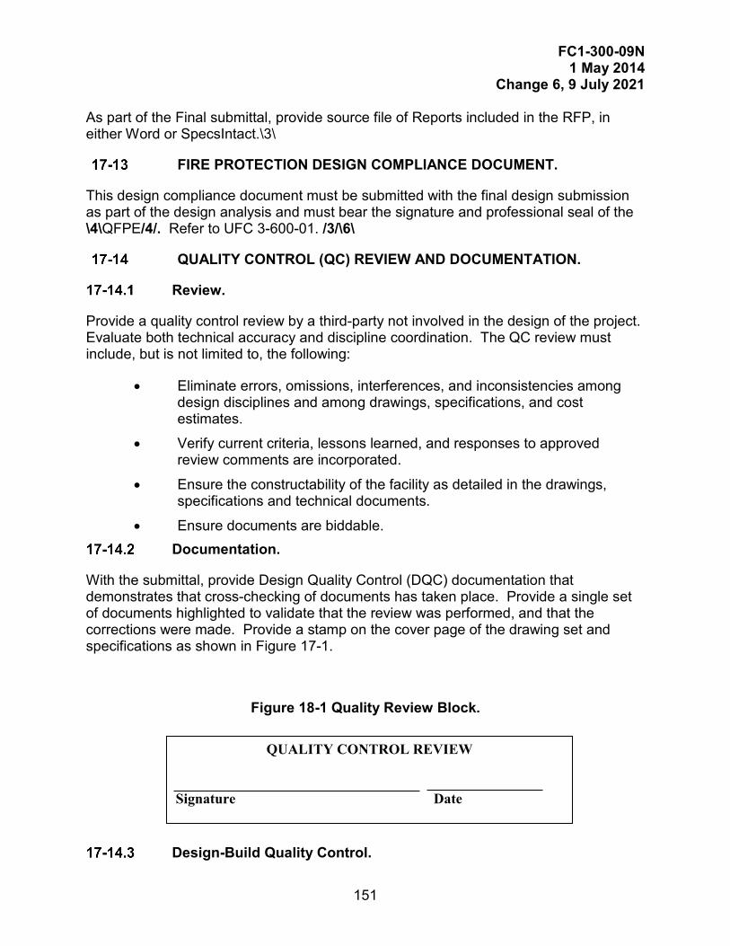
FC1-300-09N 1 May 2014
Change 6, 9 July 2021
151
As part of the Final submittal, provide source file of Reports included in the RFP, in either Word or SpecsIntact.\3\
FIRE PROTECTION DESIGN COMPLIANCE DOCUMENT.
This design compliance document must be submitted with the final design submission as part of the design analysis and must bear the signature and professional seal of the \4\QFPE/4/. Refer to UFC 3-600-01. /3/\6\
QUALITY CONTROL (QC) REVIEW AND DOCUMENTATION.
Review.
Provide a quality control review by a third-party not involved in the design of the project. Evaluate both technical accuracy and discipline coordination. The QC review must include, but is not limited to, the following:
• Eliminate errors, omissions, interferences, and inconsistencies among design disciplines and among drawings, specifications, and cost estimates.
• Verify current criteria, lessons learned, and responses to approved review comments are incorporated.
• Ensure the constructability of the facility as detailed in the drawings, specifications and technical documents.
• Ensure documents are biddable. Documentation.
With the submittal, provide Design Quality Control (DQC) documentation that demonstrates that cross-checking of documents has taken place. Provide a single set of documents highlighted to validate that the review was performed, and that the corrections were made. Provide a stamp on the cover page of the drawing set and specifications as shown in Figure 17-1.
Figure 18-1 Quality Review Block.
Design-Build Quality Control.
QUALITY CONTROL REVIEW Signature Date

FC1-300-09N 1 May 2014
Change 6, 9 July 2021
152
For Design-Build projects, this review must be a coordinated effort between the Contractor and their DOR.\3\/3//6/Additional Overseas Submittals Requirements.
Code Compliance Certification.
Design of all disciplines must comply with the applicable U.S. & Host Nation norms, regulations and all applicable U.S. Military criteria. Plans and Specifications must be certified by a Host Nation architect or engineer, registered on the country’s professional rolls, for compliance with all applicable codes and laws.
Provide this certification on the cover sheet of project drawings and specifications, in dual languages. If the specifications coversheet does not have sufficient space for this certification, provide directly behind the coversheet on a separate page, including the project information from the coversheet. The code compliance certification must be provided as indicated below, and dated, signed and stamped in accordance with the requirements set forth in Chapter 7 of this document.

FC1-300-09N 1 May 2014
Change 6, 9 July 2021
153
HAVING PARTICIPATED IN THE DESIGN OF PROJECT No. (Identify project number, project title, location), AND HAVING THOROUGHLY REVIEWED THE COMPLETED PROJECT DOCUMENTS, I DECLARE THAT THE FACILITY DESIGN INCLUDED HEREIN COMPLIES WITH ALL APPLICABLE (Identify Host Country) CODES AND LAWS.
Date Signature (Professional Seal)
Host Nation Life Safety/Building Code Compliance Documentation.
Provide the following \3\ in accordance with UFC 3-600-01/3/:
• Host Nation Life Safety and Building Code analysis.
• Comparisons of Host Nation requirements with NFPA Codes, UFC 1-200-01, and UFC 1-200-02 \3\
• Items of conflict \4\and approved resolutions/4/
• Additional costs, both engineering effort to prepare the design modification and estimated construction costs/3/
Geotechnical Report Translation.
Translate the Geotechnical Report into English. Unless stated otherwise in the contract, the boring logs must be shown in two languages, English and the local language of country of bidding and construction.

FC1-300-09N 1 May 2014
Change 6, 9 July 2021
154
This Page Intentionally Left Blank.

FC1-300-09N 1 May 2014
Change 6, 9 July 2021
155
PHASE: POST-DESIGN OR POST-RFP DEVELOPMENT SUBMITTAL REQUIREMENTS
GENERAL REQUIREMENTS.
Submissions after final design or RFP development include providing DOR and Government responses to Contractor Pre-Proposal Inquiries (PPI), Pre-Bid Inquiries (PBI), and Requests for Information (RFI), and providing amendments and contract modification documents. Submissions may include sketches, additions or corrections to drawings, specifications, or RFP, and a continuation sheet with an explanation of changes.
Changes made to the drawings, specifications, or RFP after the Final Submission are changes to the Contract Documents. Changes before contract award are amendments; changes after contract award are contract modifications.
PRE-PROPOSAL/PRE-BID INQUIRIES AND REQUESTS FOR INFORMATION.
Responses to Pre-Proposal/Pre-Bid Inquiries and Requests for Information must be responded to as quickly as possible to prevent delay to bid opening or to construction of contract. It is expected that the DOR will provide response to a PPI/PBI or RFI no later than 3 working days after notification. Where the response to a PPI/PBI or RFI requires additional time, the DOR must notify the Government Project Manager/Design Manager or ROICC/PWD as to the expected date of response. In any case, the DOR should indicate if an amendment or a contract modification is required in response to the PPI/PBI or RFI.
CHANGE NUMBERS.
The Contracting Officer for procurement assigns the Amendment or Contract Modification number. Numbers are assigned in numerical order as required. Amendment numbers are prefixed by three ciphers, for example, the first amendment is numbered "0001." The Contracting Officer prepares a cover sheet, Standard Form (SF) 30, Amendment of Solicitation/ Modification of Contract, for changes. Thus, the first page of the change's text starts on page two.
COST ESTIMATE CHANGES.
Accompany amendment or contract modification with detailed cost estimates to indicate all changes in construction cost of the project, or to substantiate a statement of no change in cost. \5\/5/Accompany contract modification with a detailed cost estimate that can be used in the negotiation of contract modification.
CHANGE FORMAT.
Provide a Continuation Sheet for an Amendment and a Proposed Change Sheet for a contract modification with an explanation of the changes. Where drawings, sketches,

FC1-300-09N 1 May 2014
Change 6, 9 July 2021
156
RFP sections, or specifications are replaced or added, attach the document PDF file separately, and reference in the Continuation Sheet or Proposed Change Sheet in accordance with guidance below. When multiple drawing, sketch, RFP section, or specification files are replaced or added, combine the documents by type into a single file, and bookmark each document \3\(example: combine the drawings into a single file and bookmark each drawing, and combine the specification sections into a single file and bookmark each section.)/3/ Follow file size limitations in accordance with Chapter \1\12/1/.
Prior to submittal of an amendment or contract modification, contact the Government representative for the number of the amendment or contract modification.
Language Format.
Use Table 19-1 "Specifications or RFP Changes Format" and Table 19-2 "Drawing Changes Format" for guidance on how to format the language for changes. Note that any additions, deletions, or replacement of complete specification sections should be done at the Table of Contents; do not list the section separately within the document by Section number and title with note to add, delete, or replace the section. Note that adding, deleting or replacing a drawing or sketch in its entirety is done at Section 00 01 15, List of Drawings; do not list each drawing or sketch separately with a note to add, delete, or revise the entire drawing.
Continuation Sheet.
Use the Continuation Sheet for Amendments. A sample Continuation Sheet is provided at Figure 18-1. Follow the specific guidance for drawing, specification, and RFP changes.
Proposed Change Sheet.
Use a Proposed Change Sheet for contract modifications. A sample sheet is provided at Figure 18-2. Use the guidance for amendments and changes for language and format.
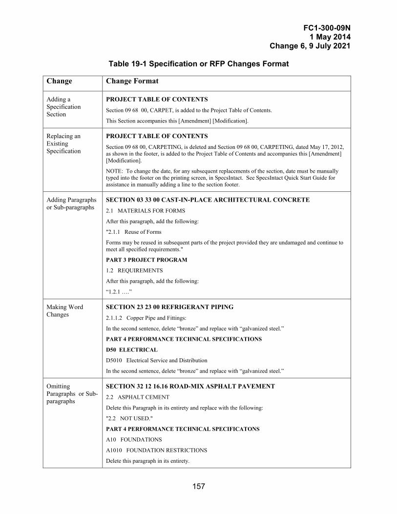
FC1-300-09N 1 May 2014
Change 6, 9 July 2021
157
Table 19-1 Specification or RFP Changes Format
Change Change Format
Adding a Specification Section
PROJECT TABLE OF CONTENTS
Section 09 68 00, CARPET, is added to the Project Table of Contents.
This Section accompanies this [Amendment] [Modification].
Replacing an Existing Specification
PROJECT TABLE OF CONTENTS
Section 09 68 00, CARPETING, is deleted and Section 09 68 00, CARPETING, dated May 17, 2012, as shown in the footer, is added to the Project Table of Contents and accompanies this [Amendment] [Modification].
NOTE: To change the date, for any subsequent replacements of the section, date must be manually typed into the footer on the printing screen, in SpecsIntact. See SpecsIntact Quick Start Guide for assistance in manually adding a line to the section footer.
Adding Paragraphs or Sub-paragraphs
SECTION 03 33 00 CAST-IN-PLACE ARCHITECTURAL CONCRETE
2.1 MATERIALS FOR FORMS
After this paragraph, add the following:
"2.1.1 Reuse of Forms
Forms may be reused in subsequent parts of the project provided they are undamaged and continue to meet all specified requirements."
PART 3 PROJECT PROGRAM
1.2 REQUIREMENTS
After this paragraph, add the following:
“1.2.1 ….”
Making Word Changes
SECTION 23 23 00 REFRIGERANT PIPING
2.1.1.2 Copper Pipe and Fittings:
In the second sentence, delete “bronze” and replace with “galvanized steel.”
PART 4 PERFORMANCE TECHNICAL SPECIFICATIONS
D50 ELECTRICAL
D5010 Electrical Service and Distribution
In the second sentence, delete “bronze” and replace with “galvanized steel.”
Omitting Paragraphs or Sub-paragraphs
SECTION 32 12 16.16 ROAD-MIX ASPHALT PAVEMENT 2.2 ASPHALT CEMENT
Delete this Paragraph in its entirety and replace with the following:
"2.2 NOT USED."
PART 4 PERFORMANCE TECHNICAL SPECIFICATONS
A10 FOUNDATIONS
A1010 FOUNDATION RESTRICTIONS
Delete this paragraph in its entirety.
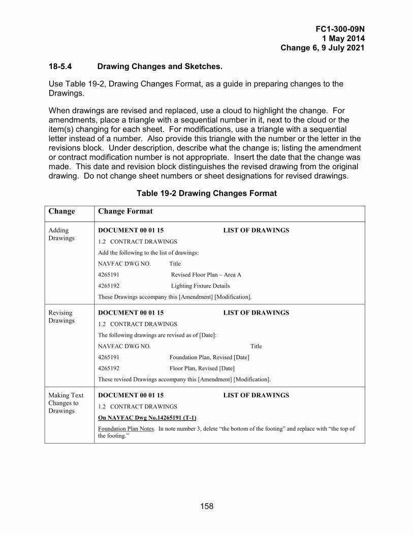
FC1-300-09N 1 May 2014
Change 6, 9 July 2021
158
Drawing Changes and Sketches.
Use Table 19-2, Drawing Changes Format, as a guide in preparing changes to the Drawings.
When drawings are revised and replaced, use a cloud to highlight the change. For amendments, place a triangle with a sequential number in it, next to the cloud or the item(s) changing for each sheet. For modifications, use a triangle with a sequential letter instead of a number. Also provide this triangle with the number or the letter in the revisions block. Under description, describe what the change is; listing the amendment or contract modification number is not appropriate. Insert the date that the change was made. This date and revision block distinguishes the revised drawing from the original drawing. Do not change sheet numbers or sheet designations for revised drawings.
Table 19-2 Drawing Changes Format
Change Change Format
Adding Drawings
DOCUMENT 00 01 15 LIST OF DRAWINGS
1.2 CONTRACT DRAWINGS
Add the following to the list of drawings:
NAVFAC DWG NO. Title
4265191 Revised Floor Plan – Area A
4265192 Lighting Fixture Details
These Drawings accompany this [Amendment] [Modification].
Revising Drawings
DOCUMENT 00 01 15 LIST OF DRAWINGS
1.2 CONTRACT DRAWINGS
The following drawings are revised as of [Date]:
NAVFAC DWG NO. Title
4265191 Foundation Plan, Revised [Date]
4265192 Floor Plan, Revised [Date]
These revised Drawings accompany this [Amendment] [Modification].
Making Text Changes to Drawings
DOCUMENT 00 01 15 LIST OF DRAWINGS
1.2 CONTRACT DRAWINGS
On NAVFAC Dwg No.14265191 (T-1)
Foundation Plan Notes. In note number 3, delete “the bottom of the footing” and replace with “the top of the footing.”
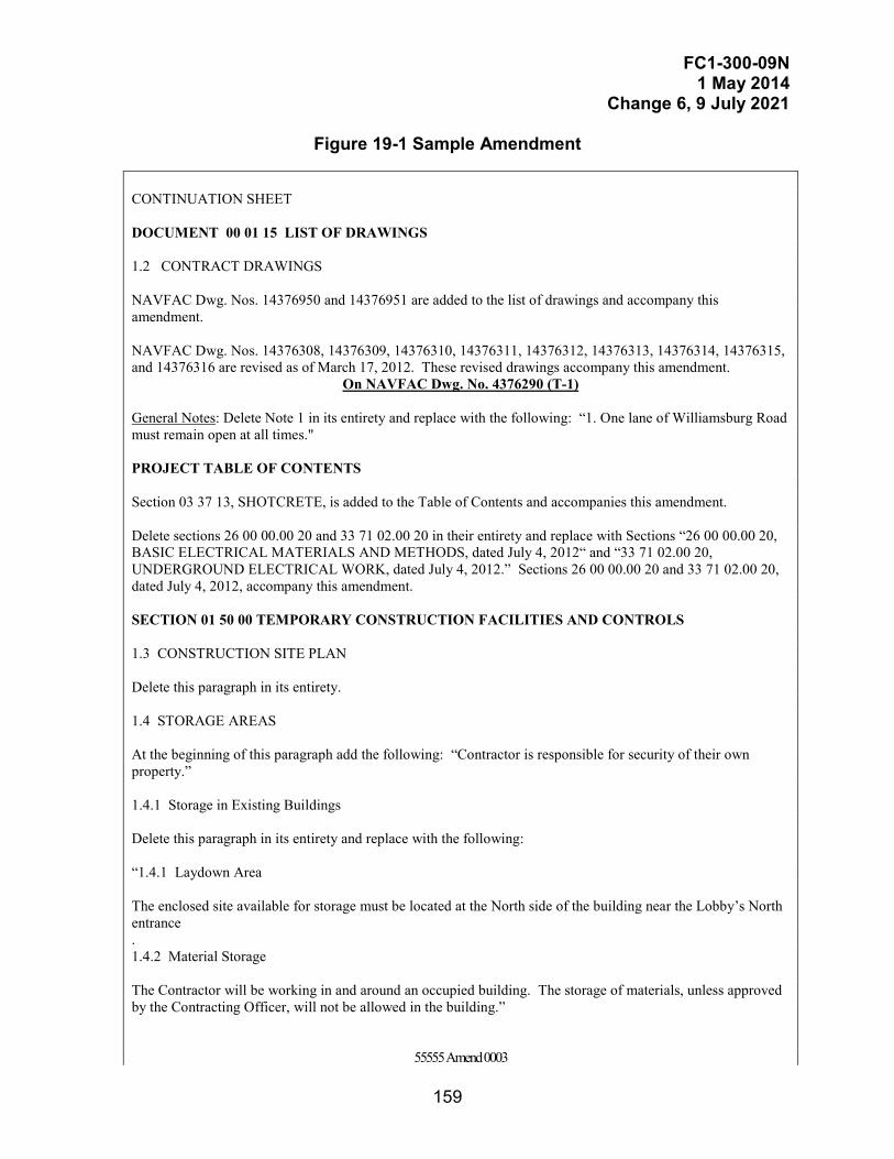
FC1-300-09N 1 May 2014
Change 6, 9 July 2021
159
Figure 19-1 Sample Amendment
CONTINUATION SHEET DOCUMENT 00 01 15 LIST OF DRAWINGS 1.2 CONTRACT DRAWINGS NAVFAC Dwg. Nos. 14376950 and 14376951 are added to the list of drawings and accompany this amendment. NAVFAC Dwg. Nos. 14376308, 14376309, 14376310, 14376311, 14376312, 14376313, 14376314, 14376315, and 14376316 are revised as of March 17, 2012. These revised drawings accompany this amendment.
On NAVFAC Dwg. No. 4376290 (T-1)
General Notes: Delete Note 1 in its entirety and replace with the following: “1. One lane of Williamsburg Road must remain open at all times." PROJECT TABLE OF CONTENTS Section 03 37 13, SHOTCRETE, is added to the Table of Contents and accompanies this amendment. Delete sections 26 00 00.00 20 and 33 71 02.00 20 in their entirety and replace with Sections “26 00 00.00 20, BASIC ELECTRICAL MATERIALS AND METHODS, dated July 4, 2012“ and “33 71 02.00 20, UNDERGROUND ELECTRICAL WORK, dated July 4, 2012.” Sections 26 00 00.00 20 and 33 71 02.00 20, dated July 4, 2012, accompany this amendment. SECTION 01 50 00 TEMPORARY CONSTRUCTION FACILITIES AND CONTROLS 1.3 CONSTRUCTION SITE PLAN Delete this paragraph in its entirety. 1.4 STORAGE AREAS At the beginning of this paragraph add the following: “Contractor is responsible for security of their own property.” 1.4.1 Storage in Existing Buildings Delete this paragraph in its entirety and replace with the following: “1.4.1 Laydown Area The enclosed site available for storage must be located at the North side of the building near the Lobby’s North entrance . 1.4.2 Material Storage The Contractor will be working in and around an occupied building. The storage of materials, unless approved by the Contracting Officer, will not be allowed in the building.”
55555 Amend 0003
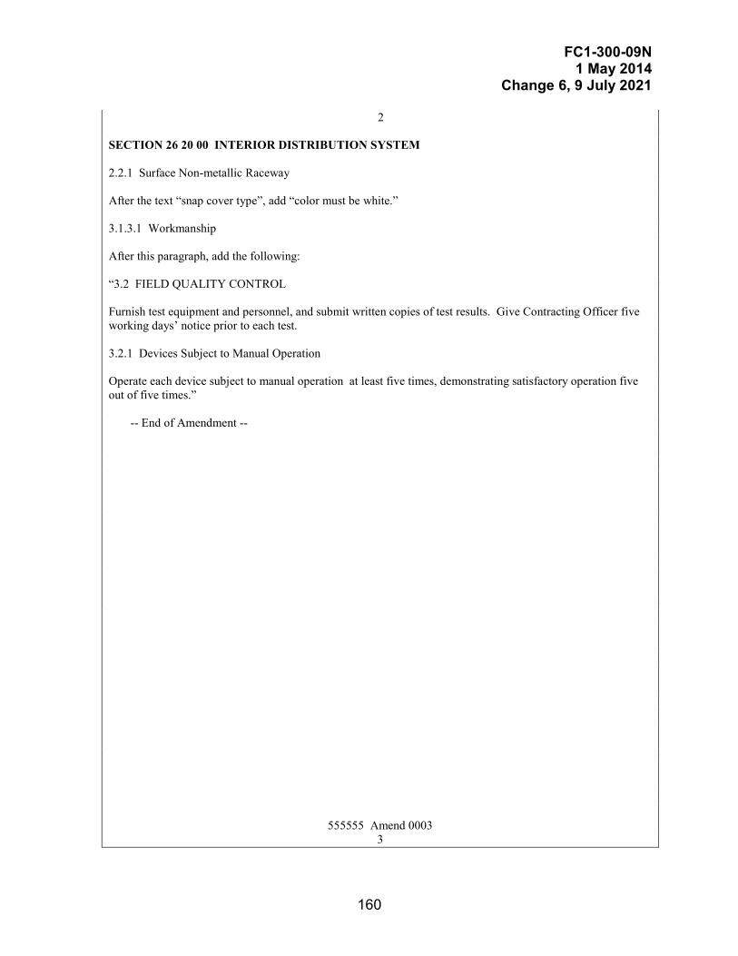
FC1-300-09N 1 May 2014
Change 6, 9 July 2021
160
2 SECTION 26 20 00 INTERIOR DISTRIBUTION SYSTEM 2.2.1 Surface Non-metallic Raceway After the text “snap cover type”, add “color must be white.” 3.1.3.1 Workmanship After this paragraph, add the following: “3.2 FIELD QUALITY CONTROL Furnish test equipment and personnel, and submit written copies of test results. Give Contracting Officer five working days’ notice prior to each test. 3.2.1 Devices Subject to Manual Operation Operate each device subject to manual operation at least five times, demonstrating satisfactory operation five out of five times.” -- End of Amendment --
555555 Amend 0003 3

FC1-300-09N 1 May 2014
Change 6, 9 July 2021
161
Figure 19-2 Sample Contract Modification
N62470-96-C-6042 NAVFAC WORK ORDER NUMBER 555555 PROPOSED CONTRACT MODIFICATION
TACTICAL SUPPORT VAN PAD AT THE
MARINE CORPS AIR STATION, NEW RIVER JACKSONVILLE, NORTH CAROLINA
DOCUMENT 00 01 15 LIST OF DRAWINGS 1.2 CONTRACT DRAWINGS
On NAVFAC Dwg. No. 4369801 (C-15)
Van Pad Pavement Detail A/C12/C12: Delete “(5.2 Mpa FLEXURAL STRENGTH)” and replace with “(4481 kPa FLEXURAL STRENGTH)”. SECTION 03 30 00 CAST-IN-PLACE CONCRETE 3.3.7 Dowel Assemblies Delete the first sentence of this paragraph. -- End of Proposed Contract Modification --
555555 PROPOSED CONTRACT MODIFICATION
1

FC1-300-09N 1 May 2014
Change 6, 9 July 2021
162
This Page Intentionally Left Blank
FC1-300-09N 1 May 2014
Change 6, 9 July 2021
163
PHASE: POST-CONSTRUCTION DOCUMENTS
PROJECT CLOSE-OUT.
The DOR may be required to execute specific project tasks during project close-out. These tasks may include preparing DD Form 1354, "Real Property Record," for Government signature, attending project close-out meetings, \3\/3/or performing other tasks. Refer to the design contract (if a Design-Bid-Build project) or the Design-Build RFP for project close-out related tasks.
Interim Form DD 1354.
Update the Draft DD Form 1354 to include any additional assets, improvements or alterations that occurred during construction. Identify costs. Submit completed form for approval to the Government. \6\\3\Attach to each DD Form 1354 updated HPSB Checklist(s) and TPC Checklist(s) for each applicable building in the project./3/ For these DD1354, ensure Block 14, “Sustainability Code” is marked with “1” for compliant. /6/
Record Drawings.
Prepare record drawings in accordance with Chapter 12.
\1\BIM Final Record Model.
Provide the final Record Model in accordance with Chapter 12./1/
Sustainability.
No later than 60 days after Beneficial Occupancy Date, provide updated \3\HPSB Checklist(s) for each applicable building in the project to Project Manager to update eProjects record. Obtain TPC Certification(s) for each applicable building in the project when all TPC organization requirements are complete. For projects with post-occupancy sustainability or energy requirements (such as commissioning), provide updated HPSB Checklist/3/ to Project Manager to finalize eProjects record. \6\Ensure copies of the following are archived to the project’s electronic sustainability folder:
• Copy of the Final Commissioning Report, and copy of the Updated Final Commissioning Report when applicable, for projects that use Government-hired Commissioning Provider.
• Copy of the Final report, validation, or certification for projects that apply sustainable third party certification.
• Contractor's completed submittal of the Sustainability eNotebook, and the Updated Sustainability eNotebook when applicable./6/

FC1-300-09N 1 May 2014
Change 6, 9 July 2021
164
This Page Intentionally Left Blank
FC1-300-09N 1 May 2014
Change 6, 9 July 2021
165
APPENDIX A REFERENCES
\4\AACE INTERNATIONAL (AACE)
https://web.aacei.org/
AACE International 56R-08, Cost Estimate Classification System - Building and General Construction/4/
\6\AACE International 91R-16, Schedule Development/6/
AMERICAN SOCIETY OF HEATING, REFRIGERATION AND AIR CONDITIONING ENGINEERS
http://www.ashrae.org/
ASHRAE 90.1, Energy Standards for Buildings, Except Low-Rise Residential Buildings
ASTM
http://www.astm.org
ASTM D1452, Standard Practice for Soil Exploration and Sampling by Auger Borings
ASTM D1586, Standard Test Method for Standard Penetration Test and Split-Barrel Sampling of Soils
ASTM D2487, Standard Practice for Classification of Soils for Engineering Purposes (Unified Soil Classification System)
ASTM D2488, Standard Practice for Description and Identification of Soils (Visual-Manual Procedure)
ASTM D3740, Standard Practice for Minimum Requirements for Agencies Engaged in Testing and/or Inspection of Soil and Rock as Used in Engineering Design and Construction
ASTM D5778, Standard Test Method for Electronic Friction Cone and Piezocone Penetration Testing of Soils
ASTM E1699, Standard Practice for Value Engineering (VE)/Value Analysis (VA) of Projects, Products, and Processes
ASTM E 2013, Standard Practice for constructing FAST Diagrams and Performing Function Analysis During Value Analysis Study

FC1-300-09N 1 May 2014
Change 6, 9 July 2021
166
FM GLOBAL
http://www.fmglobal.com
Property Loss Prevention Data Sheet 3-0, Hydraulics of Fire Protection Systems
GENERAL SERVICES ADMINISTRATION
FAR 52-236-21, Specifications and Drawings for Construction, \5\https://acquisition.gov/far/part-52#FAR_52_236_21 /5/
FAR 52-236-25, Requirements for Registration of Designers, \5\https://acquisition.gov/content/52236-25-requirements-registration-designers#i1049053http://acquisition.gov/far/current/html/52_233_240.html#wp1113529/5/
Standard Form (SF) 30, Amendment of Solicitation/ Modification of Contract, http://www.gsa.gov/portal/forms/download/116158
INTERNATIONAL CODE COUNCIL
http://www.iccsafe.org
International Building Code (IBC)
\1\International Existing Building Code (IEBC)/1/
INTERNATIONAL CODE COUNCIL
SAVE Methodology Standard 2015
UNITED STATES ARMY
A/E/C CAD Standard, \5\ https://cadbimcenter.erdc.dren.mil/aeccadstandard /5/
UNITED STATES DEPARTMENT OF DEFENSE
DFAR 227.71, Rights in Technical Data, http://www.acq.osd.mil/dpap/dars/dfarspgi/current/index.html
DFAR 227.72, Rights in Computer Software and Computer Software Documentation, http://www.acq.osd.mil/dpap/dars/dfarspgi/current/index.html
\2\/2/DFAR 252.227-7023, Drawings and Other Data to Become Property of Government, http://www.acq.osd.mil/dpap/dars/dfarspgi/current/index.html
DoD 5200.2R, Personnel Security Program, January 1987, http://www.dtic.mil/whs/directives/corres/pdf/520002r.pdf
FC1-300-09N 1 May 2014
Change 6, 9 July 2021
167
DoD Directive 4270.5, Military Construction, 5 February, 2005, http://www.dtic.mil/whs/directives/corres/pdf/427005p.pdf
\2\\6\ DODM 5200.01 Volume 4, DoD Information Security Program: Controlled Unclassified Information (CUI), https://www.esd.whs.mil/Portals/54/Documents/DD/issuances/dodi/520048p.PDF /6//2/
MIL-STD-3007, Standard Practice for Unified Facilities Criteria and Unified Facilities Guide Specifications, \5\https://assist.dla.mil /5/
Public Law 106-229, Electronic Signatures in Global and National Commerce Act, http://www.gpo.gov/fdsys/pkg/PLAW-106publ229/pdf/PLAW-106publ229.pdf
Public Law 94-168, Metric Conversion Act, http://www.gpo.gov/fdsys/pkg/STATUTE-89/pdf/STATUTE-89-Pg1007.pdf
\3\/3/UNITED STATES DEPARTMENT OF DEFENSE, UNIFIED FACILITIES CRITERIA PROGRAM
https://www.wbdg.org/ffc/dod unless otherwise noted
FC 4-721-10N, Navy and Marine Corps Unaccompanied Housing
FC 4-722-01N, Navy and Marine Corps Dining Facilities
FC 4-740-02N, Navy and Marine Corps Fitness Centers
UFC 1-200-01, \3\DoD Building Code (General Building Requirements)/3/
UFC 1-200-02 High Performance and Sustainable Building Requirements
UFC 1-300-02, Unified Facilities Guide Specifications (UFGS) Format Standard
UFC 3-101-01, Architecture
\4\UFC 3-201-02, Landscape Architecture/4/
UFC 3-210-10, Low Impact Development
UFC 3-220-01, Geotechnical Engineering
UFC 3-250-01FA, Pavement Design for Roads, Streets, Walks, and Open Storage Areas
UFC 3-260-02, Pavement Design for Airfields
UFC 3-260-03, Airfield Pavement Evaluation
FC1-300-09N 1 May 2014
Change 6, 9 July 2021
168
\1\UFC 3-301-01, Structural Engineering/1/
UFC 3-340-01, Design and Analysis of Hardened Structures to Conventional Weapons Effects (FOUO)
UFC 3-410-01, Heating, Ventilating, and Air Conditioning Systems
UFC 3-420-01, Plumbing Systems
UFC 3-501-01, Electrical Engineering
\3\UFC 3-600-01, Fire Protection for Facilities/3/
UFC 3-701-01, DoD Facilities Pricing Guide
UFC 3-730-01, Programming Cost Estimates for Military Construction
UFC 3-740-05, Handbook: Construction Cost Estimating
\3\UFC 3-810-01N, Navy and Marine Corps Environmental Engineering for Facility Construction /3/
UFC 4-010-01, DoD Minimum Antiterrorism Standards for Buildings
UFC 4-010-05, Sensitive Compartmented Information Facilities Planning, Design, and Construction \3\
UFC 4-010-06, Cybersecurity of Facility-Related Control Systems /3/
UFC 4-020-01, Security Engineering Facilities Planning Manual\4\
UFC 4-021-01, Design and O&M: Mass Notification Systems/4/
UFC 4-023-03, Design of Buildings to Resist Progressive Collapse
UFC 4-510-01, Design: Medical Military Facilities
UFC 4-610-01, Administrative Facilities
UFGS 00 01 15, List of Drawing
UFGS 00 22 13.00 20, Supplementary Instructions to Offerors
UFGS 01 11 00, Summary of Work
UFGS 01 33 00, Submittal Procedures
UFGS 01 33 00.05 20, Construction Submittal Procedures, \3\http://www.wbdg.org/ffc/navy-navfac/design-build-request-proposal/3/
FC1-300-09N 1 May 2014
Change 6, 9 July 2021
169
UFGS 01 33 10.05 20, Design Submittal Procedures, \3\http://www.wbdg.org/ffc/navy-navfac/design-build-request-proposal/3/
UFGS 01 33 29, Sustainability Requirements and Reporting
\6\\3\\3\/3//6/
\1\UFGS 01 45 00.00 20, Quality Control/1/
UFGS 01 45 00.05 20, Design and Construction Quality Control, \3\http://www.wbdg.org/ffc/navy-navfac/design-build-request-proposal/3/
\1\UFGS 01 45 35, Special Inspections
UFGS 01 45 35.05 20, Special Inspections for Design-Build, \3\http://www.wbdg.org/ffc/navy-navfac/design-build-request-proposal/3/ /1/
\1\ UFGS 01 78 24.00 20, Facility Electronic Operation and Maintenance Support Information (eOMSI)/1/
UFGS 02 82 16.00 20, Engineering Control of Asbestos Containing Materials
UFGS 10 14 00.20, Interior Signage
UNITED STATES NATIONAL CAD STANDARD
http://www.nationalcadstandard.org/
United States National CAD Standard for Architecture, Engineering, & Construction (A/E/C)
UNITED STATES NAVY
\5\/5/Electronic Project Generator (EPG), Naval Facilities Engineering Command. Contact Government administrator for Intranet address and access.
\5\/5/ NAVFAC Acquisition Supplement, (NFAS) Part 6.304, https://www.navfac.navy.mil/content/dam/navfac/Small%20Business/PDFs/Contracting_with_NAVFAC/SB-NAVFAC_Naval_Facilities_ACQ_Supplement_NOV2012.pdf
\5\/5/ \6\/6/
NAVFAC DESIGN-BUILD MASTER WEBSITE
http://www.wbdg.org/ndbm
NAVFAC Instruction 11012.119, En-(Fac 04t) Preparation of Concept Plans and Final Working Drawings and Specifications for Medical/Dental Facilities/4/\4\

FC1-300-09N 1 May 2014
Change 6, 9 July 2021
170
WHOLE BUILDING DESIGN GUIDE (WBDG)
http://www.wbdg.org
\2\eOMSI FDW, Electronic Operation and Maintenance Support Information (eOMSI), Facility Data Workbook, \3\http://www.wbdg.org/ffc/navy-navfac/bim-eomsi/3/ /2/

FC1-300-09N 1 May 2014
Change 6, 9 July 2021
171
APPENDIX B GLOSSARY
A-E Architect and Engineer
A/E/C Architect/Engineer/Contractor
\3\AFFF Aqueous Film Forming Foam/3/
CAD Computer Aided Design and Drafting
CATEX Categorical Exclusion
\5\/5/CD Compact Disk
CFA Commission of Fine Arts
CMC Commandant, Marine Corps
\4\CRB Consistency Review Board/4/
CSI Construction Specifications Institute TM
CONUS Continental United States
\6\ CLIN Contract Line Item Number /6/
\6\CSRA Cost and Schedule Risk Analysis /6/
DB Design-Build
DBB Design-Bid-Build
\3\DFPE Designated Fire Protection Engineer/3/
DoD Department of Defense
DOR Designer of Record
DQC Design Quality Control
DVD Digital Video Disc
EA Environmental Assessment
EBS Electronic Bid Solicitation
EDD Electronic Design Deliverables
EIS Environmental Impact Statement\2\

FC1-300-09N 1 May 2014
Change 6, 9 July 2021
172
eOMSI FDW Electronic Operation and Maintenance Support Information (eOMSI) Facility Data Workbook/2/
FACD Facility Analysis Concept Design
FACP Fire Alarm Control Panel
\3\FC Facility Criteria/3/
FF&E Furniture, Fixtures, and Equipment
FOSSAC Fitting Out and Supply Support Assistance Center
HPSB High Performance and Sustainable Buildings
IFP Installation Focus Plan
IP Inch-Pound (English)
KTR Contractor
LCC Life-Cycle Cost
\4\LID Low Impact Development/4/
LEED Leadership in Energy and Environmental Design
\3\NAC Notification Appliance Circuit/3/
NAVFAC Naval Facilities Engineering Command
\3\/3/NCPC National Capitol Planning Commission
NEHC Naval Environmental Health Center
\4\NEPA National Environmental Policy Act/4/
NFPA National Fire \3\Protection/3/ Agency
NIST National Institute of Science and Technology
\6\NIWC Naval Information Warfare Center/6/
\3\NLIDDC NAVFAC Low Impact Development Data Card/3/\4\NOSSA Naval Ordnance Safety and Security Activity (NOSSA)/4/
OSHA Occupational Safety and Health Administration
OCONUS Outside the Continental United States
FC1-300-09N 1 May 2014
Change 6, 9 July 2021
173
PBI Pre-Bid Inquiry
PCAS Post-Construction Award Services
\4\PDA Preliminary Design Authority/4/
PDF Portable Document File
PIF Project Information Form
PM Project Manager
PPI Pre-Proposal Inquiry
/4/PRI Project Readiness Index\4\
PROD Permit Record of Design
PWD Public Works Department
PTS Performance Technical Specification\2\
PxP Project Execution Plan/2/
\3\ QFPE Qualified Fire Protection Engineer/3/
RAC Risk Assessment Code
RAMP Requirements and Management Plan
RFI Request For Information
RFP Request For Proposal
ROICC Resident Officer in Charge of Construction
RONA Record of Non-Applicability
SAES Statement of A-E Services
\4\SAPF Special Access Program Facility/4/
\4\SCIF Sensitive Compartmented Information Facilities/4/
SHPO State Historic Preservation Officer
SI System International (Metric)
\6\/6/

FC1-300-09N 1 May 2014
Change 6, 9 July 2021
174
\5\TDC Technical Discipline Coordinator/5/
TPC Third Party Certification
UFC Unified Facilities Criteria
UFGS Unified Facilities Guide Specifications
\6\ VES Value Engineering Study /6/

FC1-300-09N 1 May 2014
Change 6, 9 July 2021
175
APPENDIX C SAMPLE DELIVERABLES
C-1 SAMPLE BID SCHEDULE FOR DESIGN-BID-BUILD PROJECT
DOCUMENT 00 22 13.00 20
SUPPLEMENTARY INSTRUCTIONS TO OFFERORS
1.1 CONTRACT LINE ITEMS The terms Offeror and Bidder and versions thereof (offer/bid) have the same definition as used within this contract. Provide the Contract Line Item (CLIN) price for the following items: CLIN 0001AA. Price for the entire work for the P136 TACAMO E-6B Hangar complete to the 5 foot line outside of the building, in accordance with the drawings and specifications, but excluding work described in CLIN 0001AB, 0001AC, 0001AD, 0002, and 0003.
CLIN DESCRIPTION PRICE
0001AA P136 TACAMO E-6B Hangar to the 5 foot line.
$____________
CLIN 0001AB. Price for the entire project Site Work, outside the 5 foot line of the E-6B Hangar facility complete in accordance with the drawings and specifications, but excluding work described in CLIN 0001AA, 0001AC, 0001AD, 0002 and 0003.
CLIN DESCRIPTION PRICE
0001AB Site Work outside the E-6B Hangar 5 foot line.
$____________
CLIN 0001AC. Price for drilled concrete pier foundation complete in accordance with drawings and specifications, and in accordance with the following schedule:
CLIN ITEM UNIT UNIT PRICE NO. UNITS TOTAL PRICE FOR
CLIN 0001AC
0001AC Drilled Concrete Pier Foundation
Linear feet
$___________ 50 $____________
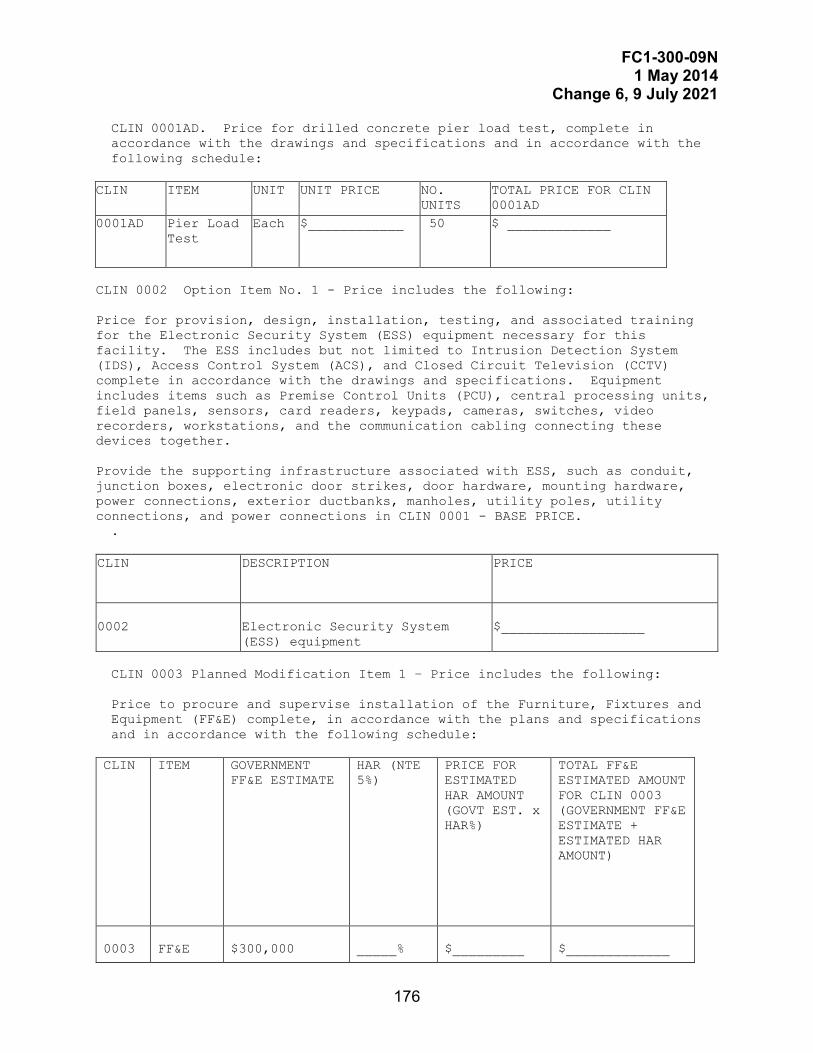
FC1-300-09N 1 May 2014
Change 6, 9 July 2021
176
CLIN 0001AD. Price for drilled concrete pier load test, complete in accordance with the drawings and specifications and in accordance with the following schedule:
CLIN ITEM UNIT UNIT PRICE NO.
UNITS TOTAL PRICE FOR CLIN 0001AD
0001AD Pier Load Test
Each $____________ 50 $ _____________
CLIN 0002 Option Item No. 1 - Price includes the following:
Price for provision, design, installation, testing, and associated training for the Electronic Security System (ESS) equipment necessary for this facility. The ESS includes but not limited to Intrusion Detection System (IDS), Access Control System (ACS), and Closed Circuit Television (CCTV) complete in accordance with the drawings and specifications. Equipment includes items such as Premise Control Units (PCU), central processing units, field panels, sensors, card readers, keypads, cameras, switches, video recorders, workstations, and the communication cabling connecting these devices together. Provide the supporting infrastructure associated with ESS, such as conduit, junction boxes, electronic door strikes, door hardware, mounting hardware, power connections, exterior ductbanks, manholes, utility poles, utility connections, and power connections in CLIN 0001 - BASE PRICE. .
CLIN DESCRIPTION PRICE
0002
Electronic Security System (ESS) equipment
$__________________
CLIN 0003 Planned Modification Item 1 – Price includes the following: Price to procure and supervise installation of the Furniture, Fixtures and Equipment (FF&E) complete, in accordance with the plans and specifications and in accordance with the following schedule: CLIN ITEM GOVERNMENT
FF&E ESTIMATE HAR (NTE 5%)
PRICE FOR ESTIMATED HAR AMOUNT (GOVT EST. x HAR%)
TOTAL FF&E ESTIMATED AMOUNT FOR CLIN 0003 (GOVERNMENT FF&E ESTIMATE + ESTIMATED HAR AMOUNT)
0003
FF&E
$300,000
_____%
$_________
$_____________

FC1-300-09N 1 May 2014
Change 6, 9 July 2021
177
1.2 GENERAL BID NOTES a. Award will be made on the total sum of Contract Line Items 0001AA,
0001AB, and the sum of the extensions under CLIN 0001AC and 0001AD. For CLIN 0001AC and 0001AD, enter unit prices and extended totals in spaces provided. If there is a difference between a unit price and the extended total, the unit price will be held to be the intended bid and the total recomputed accordingly. If an Offeror provides a total but fails to enter a unit price, the total divided by the specified quantity will be held to be the intended unit price.
b. The Government reserves the unilateral right to award CLIN 0002 to the Contractor at the proposed price within 30 calendar days after the contract award. A firm fixed proposed price is required for CLIN 0001 and CLIN 0002. No provision is made for economic price adjustment. If Options are exercised, the contract completion date remains 420 days after award of the contract.
d. Evaluation of Options (JUL 1990). Except when it is determined in
accordance with FAR 17.206 (b) not to be in the Government's best interest, the Government will evaluate offers for award purposes by adding the price for the Option(s) to the total price for the Bid Item 0001. Evaluation of options will not obligate the Government to exercise the Option(s). (FAR 52.217-5).
e. The Government may reject an offer as nonresponsive if it is materially
unbalanced as to prices for the basic requirement and the option quantities. An offer is unbalanced when it is based on prices significantly less than cost for some work and prices which are significantly overstated for other work.
1.3 PLANNED MODIFICATION BID NOTES
These notes apply to Planned Modification CLINs. a. The total estimate amount for FF&E has been identified to provide the
Offerors with the projected magnitude of effort for FF&E. The total estimate amount for the Furniture, Fixtures, and Equipment (FF&E) includes the actual cost of the FF&E including freight and installation charges. The Government FF&E Estimate is only an estimated amount.
b. If awarded, line items will be funded separately after completion of FF&E design package review, by the Government and receipt of appropriate funding by the Government. Requirements and details are provided in UFGS 01 30 01.00 20 DESIGN PROCUREMENT AND INSTALLATION OF FURNITURE, FIXTURES, AND EQUIPMENT.
c. Bonding is not required for the design, procurement and installation of FF&E.
d. Offerors may propose a Handling and Administration Rate (HAR) for the
FF&E not to exceed 5%. This fee will account for all administrative costs, overhead, bonding fees, administration of subcontracts, profit, and any other costs associated with and related to the coordination and processing of the procurement and installation of FF&E. The proposed HAR percentage will be incorporated into the contract award and will not be adjusted regardless of fluctuations from the estimate amount for the FF&E. The proposed HAR is a fixed rate.

FC1-300-09N 1 May 2014
Change 6, 9 July 2021
178
e. The Government is not obligated to award the Planned Modification line item. Should the Government choose to award the Planned Modification, the line item will be awarded as a negotiated modification to the contract/task order. The contractor's proposed HAR will be applied to all vendor/supplier costs for the FF&E.
f. If awarded, the FF&E modification will be awarded at least six months
prior to the contract completion date. A minimum of six months is required for the Contractor to purchase, deliver and install the FF&E without impacting the overall completion date of the project. The Contractor's schedule must assume the award of the FF&E as a modification. No schedule extensions will be granted if the modification is awarded at least six months prior to the contract completion date. If the Government decides to negotiate and award the furniture modification with less than six months prior to the contact completion date, the Contractor may be entitled to a contract extension and extended field overhead. A contract extension and extended field overhead will only be granted in those cases where the Contractor demonstrates that an accepted Final FF&E package was submitted within the approved schedule deadlines and sufficient lead time for the FF&E is not available and the Government's award of the modification is in the last six months of the contract.

FC1-300-09N 1 May 2014
Change 6, 9 July 2021
179
C-2 SAMPLE SYNOPSIS
\4\ \6\

FC1-300-09N 1 May 2014
Change 6, 9 July 2021
180
This Page Intentionally Left Blank

FC1-300-09N 1 May 2014
Change 6, 9 July 2021
181
APPENDIX D DESIGN ESTIMATE CLASSIFICATION AND VALUE ENGINEERING STUDY REQUIREMENTS
D-1 INDUSTRY DESIGN ESTIMATE CLASSIFICATION.
AACE International publishes Recommended Practice 56R-08, Cost Estimate System – As Applied for the Building and General Construction Industries. This recommended practice (RP) defines the relationship between the maturity of the construction project definition deliverables and the accuracy of the cost estimate based on those deliverables. The RP defines five classes of estimates based on the level of project definition maturity. These five levels overlap to account for factors of the project such as project complexity and quality of cost data.
AACE International RP 56R-08 applies to the majority of projects undertaken by NAVFAC. In the cases where a project is similar to projects from the process industry, AACE International RP 17R-97 would be acceptable as a guidance to estimate accuracy classification. It is similar in its definition of estimate maturity but does not include a table that is analogous to Table 3 from AACE RP 56R-08. \6\
Table D-1 Design Estimate Class Comparison from AACE RP 56-08. 2
Table 3 Estimate Input Checklist and Maturity Matrix from AACE International RP 56R-08 Copyright © 2020 by AACE International; all rights reserved
ESTIMATE CLASSIFICATION
Class 5 Class 4 Class 3 Class 2 Class 1 MATURITY LEVEL OF PROJECT DEFINITION DELIVERABLES 0% to 2% 1% to 15% 10% to
40% 30%
to75% 65% to 100%
GENERAL PROJECT DATA: A. SCOPE: Project Scope of Work Description P P D D D Site Infrastructure (such as Access, Construction Power, Camp) NR P D D D
B. CAPACITY: Functional Space – SF or m2 P P D D D Electrical Power Requirements (when not the primary capacity driver)
NR P D D D
Mechanical Systems NR P D D D C. PROJECT LOCATION: Building and/or Other Project Elements P P D D D
D. REQUIREMENTS:
2 Reprinted with the permission of AACE International, 1265 Suncrest Towne Center Dr., Morgantown, WV 26505 USA. Phone 304-296-8444. Internet: http://web.aacei.org Email: [email protected] Copyright © 2020 by AACE International; all rights reserved.

FC1-300-09N 1 May 2014
Change 6, 9 July 2021
182
Table 3 Estimate Input Checklist and Maturity Matrix from AACE International RP 56R-08 Copyright © 2020 by AACE International; all rights reserved
ESTIMATE CLASSIFICATION
Class 5 Class 4 Class 3 Class 2 Class 1 MATURITY LEVEL OF PROJECT DEFINITION DELIVERABLES 0% to 2% 1% to 15% 10% to
40% 30%
to75% 65% to 100%
Anti-Terrorism Force Protection P D D D D No. of Building Floors P P/D D D D Security System NR/P P D D D LEED Certification Level NR/P P/D D D D Codes and/or Standards NR P D D D Communication Systems NR P D D D Exterior Closure Description NR P D D D Finishes Descriptions NR P D D D Fire Protection and Life Safety NR P D D D Environmental Monitoring NR NR P P D E. TECHNOLOGY SELECTION: N/A F. STRATEGY: Contracting/Sourcing NR P D D D Escalation NR P D D D G. PLANNING: Logistics Plan P P P D D Integrated Project Plan NR P D D D Project Code of Accounts NR P D D D Project Master Schedule NR P D D D Regulatory Approval & Permitting NR P D D D Risk Register NR P D D D Stakeholder Consultation /Engagement / Management Plan NR P D D D
Work Breakdown Structure NR P D D D Startup and Commissioning Plan NR P P/D D D Storm Water Management Plan NR P P/D D D H. STUDIES: Environmental Impact / Sustainability Assessment NR P D D D
Environmental Existing Conditions NR P D D D Soils and Hydrology NR P D D D
TECHNICAL DELIVERABLES Site Plan S P C C C Design Specifications NR S/P C C C Electrical One-line Drawings NR S/P C C C

FC1-300-09N 1 May 2014
Change 6, 9 July 2021
183
Table 3 Estimate Input Checklist and Maturity Matrix from AACE International RP 56R-08 Copyright © 2020 by AACE International; all rights reserved
ESTIMATE CLASSIFICATION
Class 5 Class 4 Class 3 Class 2 Class 1 MATURITY LEVEL OF PROJECT DEFINITION DELIVERABLES 0% to 2% 1% to 15% 10% to
40% 30%
to75% 65% to 100%
General Equipment Arrangement Drawings NR S/P C C C
Plot Plans / Facility Layouts NR S/P C C C Room Classification Data Sheet NR S/P C C C Room Layout Drawings NR S/P C C C Construction Permits NR S/P P/C C C Building Plan Views, Sections and Elevations NR S/P P C C
Civil / Site / Structural / Architectural Discipline Drawings NR S/P P C C
Codes and Standards Drawings NR S/P P C C Demolition Plan and Drawings NR S/P P C C Erosion Control Plan and Drawings NR S/P P C C Exterior Elevations NR S/P P C C Finish Schedule NR S/P P C C Fire Protection and Life Safety Drawings and Details NR S/P P C C
Furniture Plans, Schedules and Drawings NR S/P P C C
Interior Section Views NR S/P P C C Landscape Drawings NR S/P P C C Plumbing Drawings NR S/P P C C Roof Plan, Drawings and Details NR S/P P C C Storm Water Drawings NR S/P P C C Window Schedules NR S/P P P/C C Door Schedules NR S/P P C C Restroom Schedules NR S/P P C C Signage Drawings and Schedules NR S/P P C C Partition or Wall Types NR S/P S/P C C Electrical Schedules NR NR/S P P/C C Equipment Datasheets NR NR/S P P/C C Equipment Lists: Electrical NR NR/S P P/C C Equipment Lists: Process / Utility / Mechanical NR NR/S P P/C C
Instrument and Control Schedules NR NR/S P P/C C Instrument Datasheets NR NR/S P P/C C Piping Schedules NR NR/S P P/C C
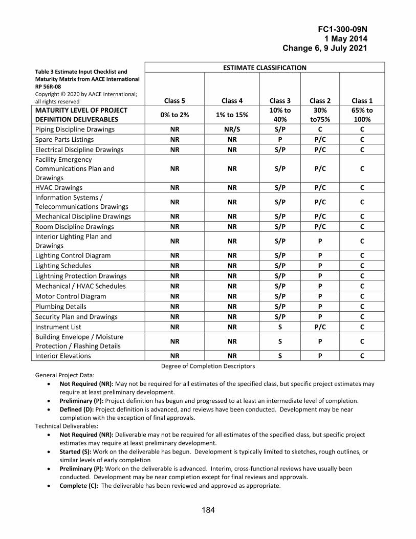
FC1-300-09N 1 May 2014
Change 6, 9 July 2021
184
Table 3 Estimate Input Checklist and Maturity Matrix from AACE International RP 56R-08 Copyright © 2020 by AACE International; all rights reserved
ESTIMATE CLASSIFICATION
Class 5 Class 4 Class 3 Class 2 Class 1 MATURITY LEVEL OF PROJECT DEFINITION DELIVERABLES 0% to 2% 1% to 15% 10% to
40% 30%
to75% 65% to 100%
Piping Discipline Drawings NR NR/S S/P C C Spare Parts Listings NR NR P P/C C Electrical Discipline Drawings NR NR S/P P/C C Facility Emergency Communications Plan and Drawings
NR NR S/P P/C C
HVAC Drawings NR NR S/P P/C C Information Systems / Telecommunications Drawings NR NR S/P P/C C
Mechanical Discipline Drawings NR NR S/P P/C C Room Discipline Drawings NR NR S/P P/C C Interior Lighting Plan and Drawings NR NR S/P P C
Lighting Control Diagram NR NR S/P P C Lighting Schedules NR NR S/P P C Lightning Protection Drawings NR NR S/P P C Mechanical / HVAC Schedules NR NR S/P P C Motor Control Diagram NR NR S/P P C Plumbing Details NR NR S/P P C Security Plan and Drawings NR NR S/P P C Instrument List NR NR S P/C C Building Envelope / Moisture Protection / Flashing Details NR NR S P C
Interior Elevations NR NR S P C Degree of Completion Descriptors
General Project Data: • Not Required (NR): May not be required for all estimates of the specified class, but specific project estimates may
require at least preliminary development. • Preliminary (P): Project definition has begun and progressed to at least an intermediate level of completion. • Defined (D): Project definition is advanced, and reviews have been conducted. Development may be near
completion with the exception of final approvals. Technical Deliverables:
• Not Required (NR): Deliverable may not be required for all estimates of the specified class, but specific project estimates may require at least preliminary development.
• Started (S): Work on the deliverable has begun. Development is typically limited to sketches, rough outlines, or similar levels of early completion
• Preliminary (P): Work on the deliverable is advanced. Interim, cross-functional reviews have usually been conducted. Development may be near completion except for final reviews and approvals.
• Complete (C): The deliverable has been reviewed and approved as appropriate.
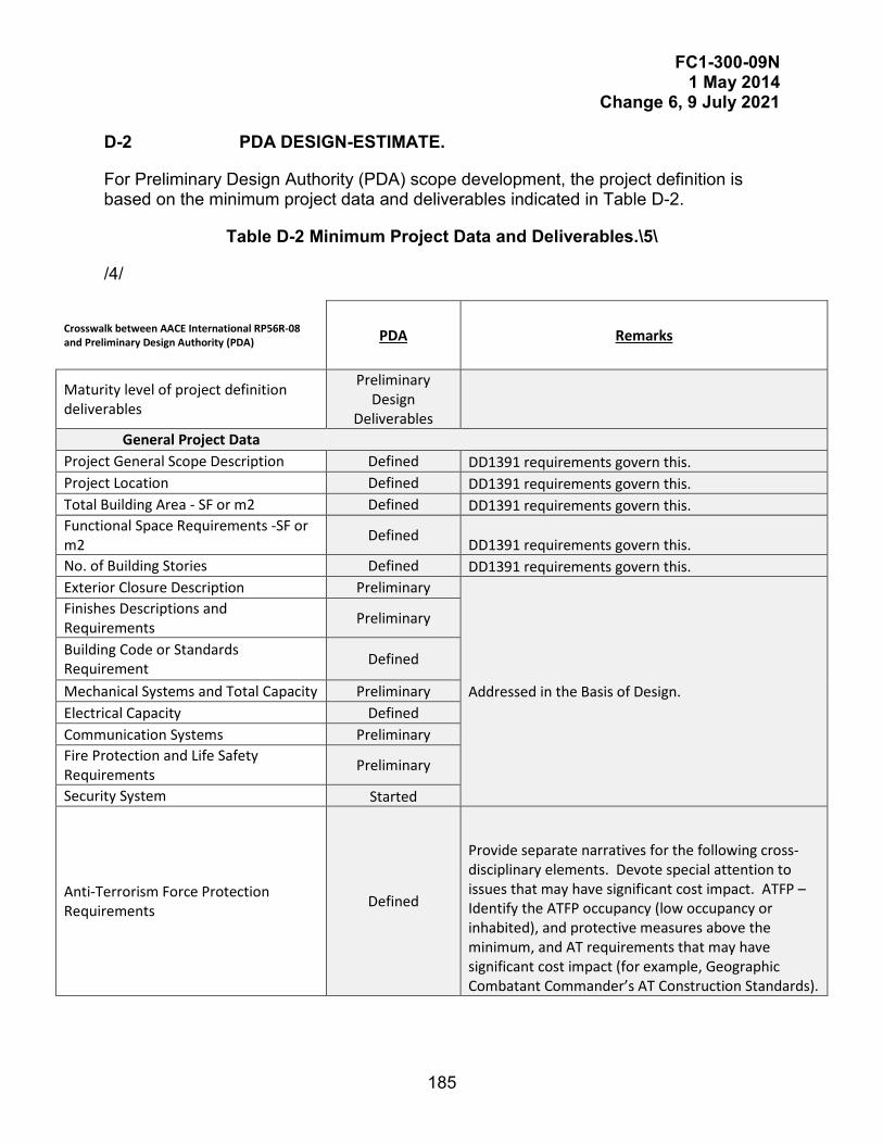
FC1-300-09N 1 May 2014
Change 6, 9 July 2021
185
D-2 PDA DESIGN-ESTIMATE.
For Preliminary Design Authority (PDA) scope development, the project definition is based on the minimum project data and deliverables indicated in Table D-2.
Table D-2 Minimum Project Data and Deliverables.\5\
/4/
Crosswalk between AACE International RP56R-08 and Preliminary Design Authority (PDA) PDA Remarks
Maturity level of project definition deliverables
Preliminary Design
Deliverables General Project Data
Project General Scope Description Defined DD1391 requirements govern this. Project Location Defined DD1391 requirements govern this. Total Building Area - SF or m2 Defined DD1391 requirements govern this. Functional Space Requirements -SF or m2 Defined DD1391 requirements govern this. No. of Building Stories Defined DD1391 requirements govern this. Exterior Closure Description Preliminary
Addressed in the Basis of Design.
Finishes Descriptions and Requirements Preliminary
Building Code or Standards Requirement Defined
Mechanical Systems and Total Capacity Preliminary Electrical Capacity Defined Communication Systems Preliminary Fire Protection and Life Safety Requirements Preliminary
Security System Started
Anti-Terrorism Force Protection Requirements Defined
Provide separate narratives for the following cross-disciplinary elements. Devote special attention to issues that may have significant cost impact. ATFP – Identify the ATFP occupancy (low occupancy or inhabited), and protective measures above the minimum, and AT requirements that may have significant cost impact (for example, Geographic Combatant Commander’s AT Construction Standards).
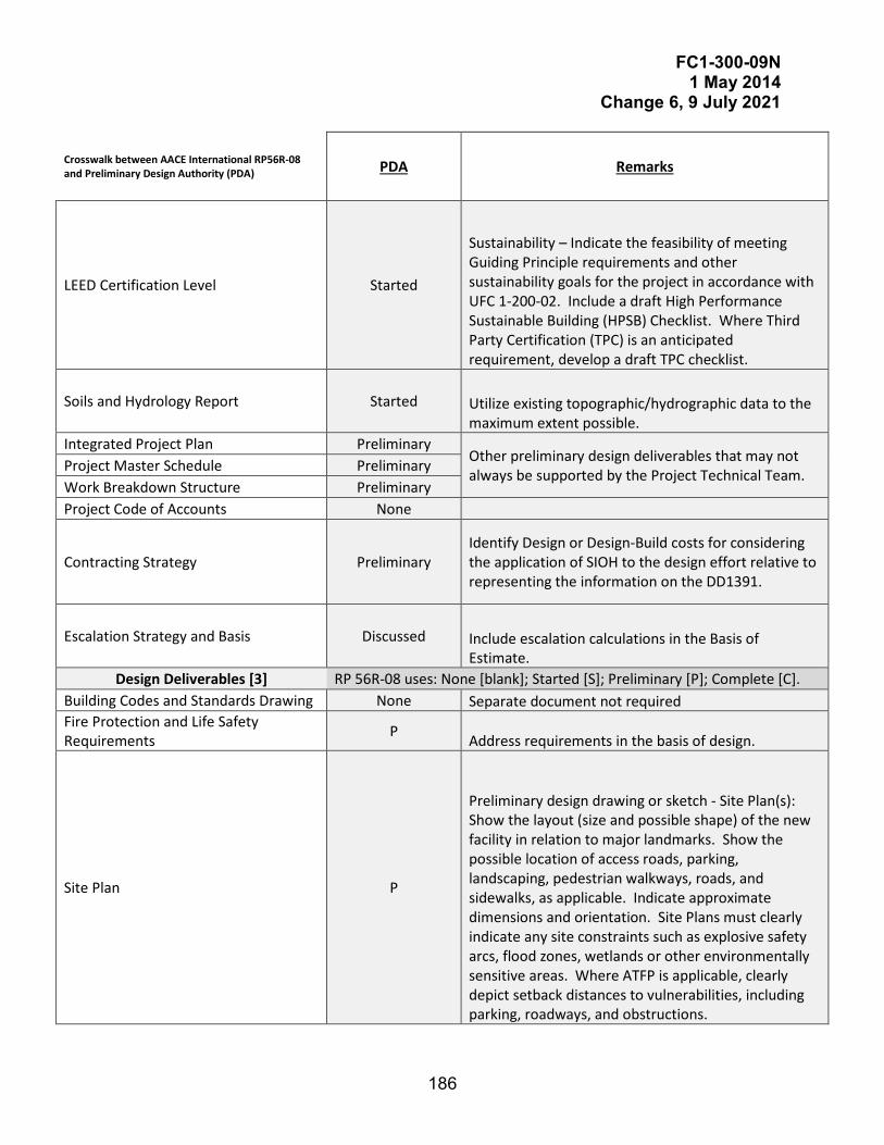
FC1-300-09N 1 May 2014
Change 6, 9 July 2021
186
Crosswalk between AACE International RP56R-08 and Preliminary Design Authority (PDA) PDA Remarks
LEED Certification Level Started
Sustainability – Indicate the feasibility of meeting Guiding Principle requirements and other sustainability goals for the project in accordance with UFC 1-200-02. Include a draft High Performance Sustainable Building (HPSB) Checklist. Where Third Party Certification (TPC) is an anticipated requirement, develop a draft TPC checklist.
Soils and Hydrology Report Started Utilize existing topographic/hydrographic data to the maximum extent possible.
Integrated Project Plan Preliminary Other preliminary design deliverables that may not always be supported by the Project Technical Team. Project Master Schedule Preliminary
Work Breakdown Structure Preliminary Project Code of Accounts None
Contracting Strategy Preliminary Identify Design or Design-Build costs for considering the application of SIOH to the design effort relative to representing the information on the DD1391.
Escalation Strategy and Basis Discussed Include escalation calculations in the Basis of Estimate.
Design Deliverables [3] RP 56R-08 uses: None [blank]; Started [S]; Preliminary [P]; Complete [C]. Building Codes and Standards Drawing None Separate document not required Fire Protection and Life Safety Requirements P Address requirements in the basis of design.
Site Plan P
Preliminary design drawing or sketch - Site Plan(s): Show the layout (size and possible shape) of the new facility in relation to major landmarks. Show the possible location of access roads, parking, landscaping, pedestrian walkways, roads, and sidewalks, as applicable. Indicate approximate dimensions and orientation. Site Plans must clearly indicate any site constraints such as explosive safety arcs, flood zones, wetlands or other environmentally sensitive areas. Where ATFP is applicable, clearly depict setback distances to vulnerabilities, including parking, roadways, and obstructions.

FC1-300-09N 1 May 2014
Change 6, 9 July 2021
187
Crosswalk between AACE International RP56R-08 and Preliminary Design Authority (PDA) PDA Remarks
Existing Site Plan P Preliminary design drawing or sketch - Vicinity Map and Location Plan
Demolition Plan and Drawings P Preliminary design drawing or sketch - Demolition Plan: Show facilities to be demolished (if required)
Utility Plan and Drawings P Preliminary design drawing or sketch - Utilities Plans: Show utility lines and their points of connection in relation to existing adjacent structures, roads, and utilities. Show off-site utility upgrade requirements needed to support the project. Show civil, electrical and telecommunication utilities to clearly convey the scope and quantities associated with various utility improvements. On large utility distribution projects, provide one-line diagrams of electrical and telecommunication utilities.
Site Electrical Plan and Drawings P
Site Lighting Plan and Drawings P
Site Communication Plan and Drawings P
Erosion Control Plan and Drawings S/P Address requirements in the basis of design - Basis of design for site and utility related disciplines (for example, civil, electrical, telecommunication) must identify the design assumptions for Supporting Facilities, as required to support quantities and unit costs for Supporting Facilities. Consult with landscape architecture personnel for select projects, where a large proportion of total cost is likely to be associated with landscaping requirements.
Stormwater Plan and Drawings S/P
Landscaping Plan and Drawings S/P
Exterior Elevations P Preliminary design drawing or sketch - Building Elevations: Provide schematic elevations indicating the building exterior character.
Interior Elevations
No drawing, plan, diagram or schedule
Address requirements in the Basis of Design - Basis of design for building systems (for example, architecture, structural, mechanical, electrical, fire protection) must identify the discipline-specific design assumptions, as required to support a parametric estimate on the Primary Facility. Consult with interior design personnel for select projects, where unique interior design requirements cannot be captured by standard parametric estimating techniques for the facility-type.
Interior Section Views Partition or Wall Types Finish Schedule Door Schedules Window Schedules Restroom Schedules Furniture Plans, Schedules and Drawings Signage Drawings and Schedules Fire Protection Plan, Drawings and Details
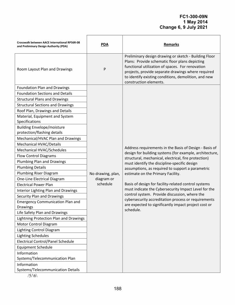
FC1-300-09N 1 May 2014
Change 6, 9 July 2021
188
Crosswalk between AACE International RP56R-08 and Preliminary Design Authority (PDA) PDA Remarks
Room Layout Plan and Drawings P
Preliminary design drawing or sketch - Building Floor Plans: Provide schematic floor plans depicting functional utilization of spaces. For renovation projects, provide separate drawings where required to identify existing conditions, demolition, and new construction elements.
Foundation Plan and Drawings
No drawing, plan, diagram or schedule
Address requirements in the Basis of Design - Basis of design for building systems (for example, architecture, structural, mechanical, electrical, fire protection) must identify the discipline-specific design assumptions, as required to support a parametric estimate on the Primary Facility. Basis of design for facility-related control systems must indicate the Cybersecurity Impact Level for the control system. Provide discussion, where the cybersecurity accreditation process or requirements are expected to significantly impact project cost or schedule.
Foundation Sections and Details Structural Plans and Drawings Structural Sections and Drawings Roof Plan, Drawings and Details Material, Equipment and System Specifications Building Envelope/moisture protection/flashing details Mechanical/HVAC Plan and Drawings Mechanical HVAC/Details Mechanical HVAC/Schedules Flow Control Diagrams Plumbing Plan and Drawings Plumbing Details Plumbing Riser Diagram One-Line Electrical Diagram Electrical Power Plan Interior Lighting Plan and Drawings Security Plan and Drawings Emergency Communication Plan and Drawings Life Safety Plan and Drawings Lightning Protection Plan and Drawings Motor Control Diagram Lighting Control Diagram Lighting Schedules Electrical Control/Panel Schedule Equipment Schedule Information Systems/Telecommunication Plan Information Systems/Telecommunication Details
/5/\6\

FC1-300-09N 1 May 2014
Change 6, 9 July 2021
189
D-3 VALUE ENGINEERING STUDY (VES) REQUIREMENTS.
Provide the service of a Value Engineering (VE)/Value Analysis (VA) team led by a Value Study Team Leader (VSTL) to conduct a Value Engineering Study (VES) to include a Value Engineering Workshop (VEW). The VEW may be combined with other meetings or workshops associated with the project. The VES must follow the methodology advocated by SAVE International and will be documented in a report. Each of the alternatives evaluated as part of the VES must be achievable with the project’s construction award amount.
The following industry standards apply to the extent feasible in accordance with the level of design development:
• SAVE Methodology Standard 2015
• ASTM E1699 Standard Practice for Value Engineering (VE)/Value Analysis (VA) of Projects, Products, and Processes (Latest Revision)
• ASTM E2013 Standard Practice for Constructing FAST Diagrams and Performing Function Analysis During Value Analysis Study (Latest Revision)
D-3.1 VE/VA Team Requirements.
Value Study Team Leader (VSTL): Provide a VSTL certified by SAVE International as a Certified Value Specialist, with experience in preparing Value Studies and conducting VES workshops for projects related to the construction of buildings and other engineered systems. The VSTL will be responsible for leading the VE/VA team, resolving issues to the maximum extent possible, documenting meetings, organizing the study materials for on-site use/approval, and providing the VES Report.
The Designer of Record (DOR) Project Delivery Team (PDT) will provide the VE/VA Technical Team.
D-3.2 VES Kick Off Meeting.
Conduct the VES meeting via teleconference and review workshop preparations, scope, expectations, roles and responsibilities, schedules and documentation requirements. This meeting will generally last one hour and must be attended by the VSTL and the Project Manager (PM) and Design Manager (DM) from the DOR.
D-3.3 Value Engineering Workshop (VEW).
The VEW must be attended by the VSTL as well as the key members of the DOR’s PDT. This is to include the DOR’s PM, DM, Architect, Structural Engineer, Mechanical Engineer, Electrical Engineer, Civil Engineer, Landscape Architect, Cost Engineer, Fire Protection Engineer, Interior Designer, CTS-D, and Geotechnical Engineer. Other technical disciplines may be included if approved by the NAVFAC PM, DM, or Cost TDC. The VSTL will lead the VEW following the six-step job plan consistent with the
FC1-300-09N 1 May 2014
Change 6, 9 July 2021
190
SAVE International Value Standard, ASTM E1699 and ASTM E2013. A comprehensive VEW will establish all six steps during the on-workshop. An abbreviated VEW will accomplish the first three steps during the workshop and the remaining three steps after the workshop. The six phases of the Value Methodology Job Plan are:
1) Information Phase
2) Function Analysis Phase (including FAST Diagrams as per ASTM E2013)
3) Creative Phase
4) Evaluation Phase
5) Development Phase
6) Presentation Phase
D-3.3.1 VEW Preparations.
Provide a meeting facility to accommodate the anticipated number of participants. The facility is to provide access to photocopying for handout material and access to the Internet for Email and research by participants.
Complete the following items prior to the start of the VEW:
As a minimum, review the available documentation gathered by the NAVFAC PDT. This includes but is not limited to:
• All information included or cited in the project’s scope of services (SAES or SIHS as appropriate)
• Any Design Instructions from other agencies
• Design authorization and programming documents
• Studies, cost estimates, and other information. The VSTL is to prepare a sample presentation format for the use of
the DOR’s VE/VA Technical Team.
Arrange for a site visit prior to the workshop to allow the VSTL and the VE/VA Technical Team to become familiar with the project site. Coordinate this effort with the NAVFAC PM/DM
Prepare a presentation handout for the anticipated number of participants including:
• A discussion of the overall VES methodology
• A discussion of the scope of work as currently developed

FC1-300-09N 1 May 2014
Change 6, 9 July 2021
191
• A discussion of the current program amount allocated for the project
• A discussion of the current estimated construction cost estimate
• A capital cost model as indicated in ASTM E1699, 7.28
• A discussion of the project documentation provided for this study, noting that copies are available during the workshop
• A discussion of the performance and acceptance requirements for evaluating alternatives in accordance with ASTM E1699, 7.2.5.
D-3.3.2 VEW Process.
The DOR’s PDT members will explain how the current scope/design accomplishes the stakeholder objectives.
The workshop participants will generate a list of ideas for project improvement followed by an evaluation of those ideas. The evaluation will include input from key stakeholder decision makers before proceeding with development recommendations.
The VE/VA Technical Team will develop selected ideas into alternatives with enough documentation to allow decision makers to determine if the alternative should be implemented.
The VSTL, with input from NAVFAC, will evaluate each alternative in accordance with the pre-determined performance and acceptance requirements.
The VSTL will present the alternatives to the key stakeholder decision makers on the final day of the workshop.
D-3.4 VES Report.
Provide a report documenting the VES process and its application to this project by capturing the process and the alternatives considered or recommended.
Include the following in the report:
• Project Objectives
• Project Description
• Scope Analysis
• VES Procedure
FC1-300-09N 1 May 2014
Change 6, 9 July 2021
192
• VES Alternatives and associated savings/improvements considered
• VES Alternatives and associated savings/improvements recommended
• Copy of the original Study Team Presentation Handout D-3.4.1 Comprehensive Workshop VES Report.
Preliminary VES Report: Include a collection of the findings of all (6) phases of the Value Methodology Job Plan at the conclusion of the workshop.
Draft Final VES Report: Incorporate all revisions from previous submittal comments and include a list of final recommendations.
Final VES Report: Incorporate revisions from previous submittal comments and the implementation decisions captured during the Decision/Implementation Meeting.
D-3.4.2 Abbreviated Workshop VES Report.
Preliminary VES Report: Include a collection of draft/summaries of the findings at the conclusion of the workshop. As a minimum address the first (3) phases of the Value Methodology Job Plan covered during the workshop.
Interim VES Report: Include revisions of the Preliminary VES Report and include draft/summaries of the last (3) phases of the Value Methodology Job Plan.
Draft Final VES Report: Incorporate all revisions from previous submittal comments and include a list of final recommendations
Final VES Report: Incorporate revisions from previous submittal comments and the implementation decisions captured during the Decision/Implementation Meeting.
D-3.4.3 VES Decision/Implementation Meeting.
The VSTL must conduct a four-hour Decision/Implementation Meeting via teleconference. This meeting is to assist key project stakeholders in the selection of which of the developed alternatives to implement. The VES Decision/Implementation Meeting must be attended by the DOR’s PDT who will be working on this project. This is to include the DOR’s PM, DM, Architect, Structural Engineer, Mechanical Engineer, Electrical Engineer, Civil Engineer, Landscape Architect, Cost Engineer, Fire Protection Engineer, Interior Designer, CTS-D, and Geotechnical Engineer. Other technical disciplines may be included if approved by the NAVFAC PM, DM, or Cost TDC.
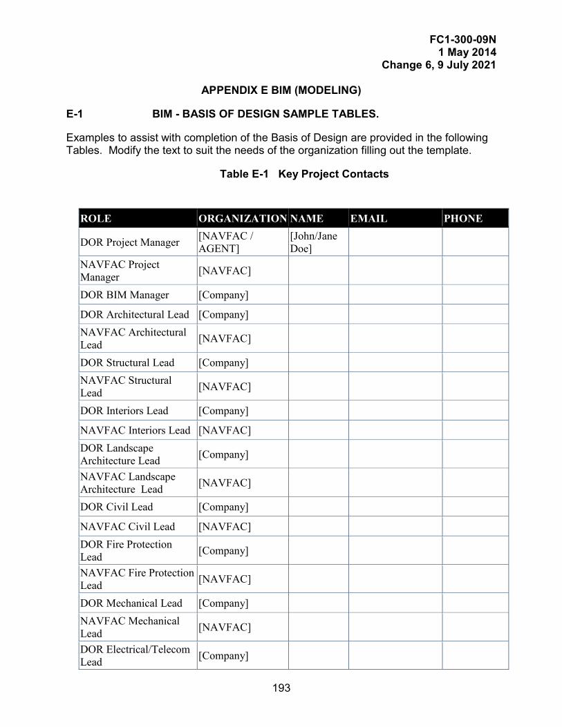
FC1-300-09N 1 May 2014
Change 6, 9 July 2021
193
APPENDIX E BIM (MODELING)
E-1 BIM - BASIS OF DESIGN SAMPLE TABLES.
Examples to assist with completion of the Basis of Design are provided in the following Tables. Modify the text to suit the needs of the organization filling out the template.
Table E-1 Key Project Contacts
ROLE ORGANIZATION NAME EMAIL PHONE
DOR Project Manager [NAVFAC / AGENT]
[John/Jane Doe]
NAVFAC Project Manager [NAVFAC]
DOR BIM Manager [Company]
DOR Architectural Lead [Company] NAVFAC Architectural Lead [NAVFAC]
DOR Structural Lead [Company] NAVFAC Structural Lead [NAVFAC]
DOR Interiors Lead [Company]
NAVFAC Interiors Lead [NAVFAC] DOR Landscape Architecture Lead [Company]
NAVFAC Landscape Architecture Lead [NAVFAC]
DOR Civil Lead [Company]
NAVFAC Civil Lead [NAVFAC] DOR Fire Protection Lead [Company]
NAVFAC Fire Protection Lead [NAVFAC]
DOR Mechanical Lead [Company] NAVFAC Mechanical Lead [NAVFAC]
DOR Electrical/Telecom Lead [Company]
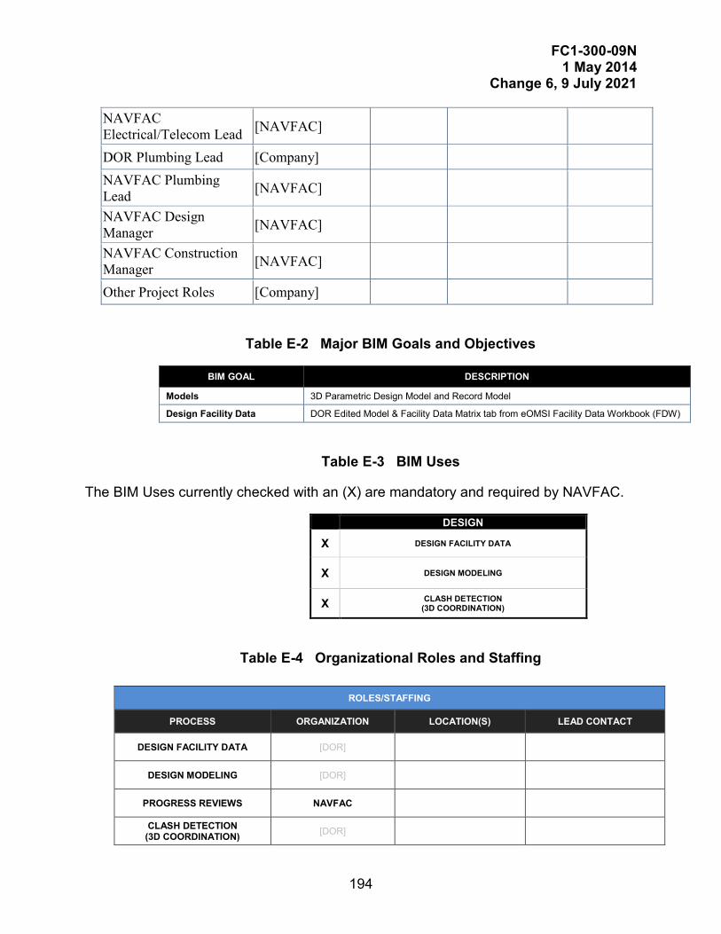
FC1-300-09N 1 May 2014
Change 6, 9 July 2021
194
Table E-2 Major BIM Goals and Objectives
BIM GOAL DESCRIPTION
Models 3D Parametric Design Model and Record Model
Design Facility Data DOR Edited Model & Facility Data Matrix tab from eOMSI Facility Data Workbook (FDW)
Table E-3 BIM Uses
The BIM Uses currently checked with an (X) are mandatory and required by NAVFAC.
DESIGN
X DESIGN FACILITY DATA
X DESIGN MODELING
X CLASH DETECTION (3D COORDINATION)
Table E-4 Organizational Roles and Staffing
NAVFAC Electrical/Telecom Lead [NAVFAC]
DOR Plumbing Lead [Company] NAVFAC Plumbing Lead [NAVFAC]
NAVFAC Design Manager [NAVFAC]
NAVFAC Construction Manager [NAVFAC]
Other Project Roles [Company]
ROLES/STAFFING
PROCESS ORGANIZATION LOCATION(S) LEAD CONTACT
DESIGN FACILITY DATA [DOR]
DESIGN MODELING [DOR]
PROGRESS REVIEWS NAVFAC
CLASH DETECTION (3D COORDINATION) [DOR]
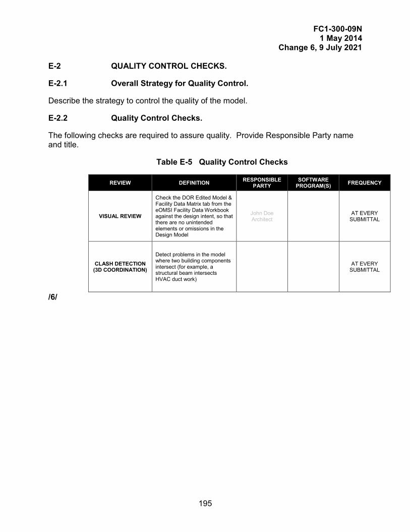
FC1-300-09N 1 May 2014
Change 6, 9 July 2021
195
E-2 QUALITY CONTROL CHECKS.
E-2.1 Overall Strategy for Quality Control.
Describe the strategy to control the quality of the model.
E-2.2 Quality Control Checks.
The following checks are required to assure quality. Provide Responsible Party name and title.
Table E-5 Quality Control Checks
REVIEW DEFINITION RESPONSIBLE PARTY
SOFTWARE PROGRAM(S) FREQUENCY
VISUAL REVIEW
Check the DOR Edited Model & Facility Data Matrix tab from the eOMSI Facility Data Workbook against the design intent, so that there are no unintended elements or omissions in the Design Model
John Doe Architect AT EVERY
SUBMITTAL
CLASH DETECTION (3D COORDINATION)
Detect problems in the model where two building components intersect (for example, a structural beam intersects HVAC duct work)
AT EVERY SUBMITTAL
/6/

FC1-300-09N 1 May 2014
Change 6, 9 July 2021
196
This Page Intentionally Left Blank