
The new triazine-based porous copper phosphonate [Cu3(PPT ...
Upload
nguyendieuCategory
view
214download
1
The Iraqi Journal For Mechanical And Material Engineering, Vol.16, No3, 2016
285
FABRICATION POROUS COPPER BY SINTERING’S
TECHNIQUE UNDER VACUUM CONDITIONS
Salah N. Alnomani1 and Abdalwahid K. Rajih2
1University of Kerbala, Department of Mechanical Eng., Kerbala, Iraq
2Babylon University, College of Materials Eng., Iraq
_______________________________________________________________ ABSTRACT : In this study, porous copper was produced using powder metallurgical techniques. Zinc element (21%wt) was used as a transitional element to be pulled during sintering process under vacuum environment. A set of samples was produced with different sintering’s conditions to investigate the optimal parameters for production of porous copper. SEM test was used to measure the resulted porosity for the prepared samples. It was found that 3 hours is a sufficient duration for the first stage of sintering at (350oC) and for the second stages at (850oC) to pull all of the zinc vapors and thus get the highest percentage of porosity for the remaining copper which was found to be (19%). Key words: Metal foam, porous copper, membrane, fuel cell, powder metallurgy, sintering.
انتاج نحاس مسامي باستخدام تقنیة التلبید في أجواء مفرغة
راجح صالح نوري النعماني كاظم عبدالواحدد.
: الخالصةفي هذه الدراسة، تم إنتاج النحاس المسامي �استخدام تكنولوج�ا المساحیق. وقد استخدم عنصر
كعنصر انتقالي لیتم سح�ه �عد ذلك خالل عمل�ة التلبید في ظل أجواء ) wt%21الزنك بنس�ة وزن�ة (مفرغة. تم انتاج مجموعة من العینات تحت ظروف تلبید مختلفة لغرض استقصاء تلك الظروف التي تحقق أفضل المعاییر في انتاج النحاس المسامي. تم استخدام المجهر األلكتروني لغرض ق�اس
وقد وجد أن التلبید لمدة ثالث ساعات خالل المرحلة األولى بدرجة حرارة المسام�ة للعینات المعدة. )350oC () 850و للمرحلة الثان�ة بدرجة حرارةoC ( للتلبید ینتج عنه تبخر محتوى الزنك �شكل ش�ه
. )%19كامل و�التالي الحصول على أعلى نس�ة من المسام�ة للنحاس المت�قي بلغت ق�متها (
Fabrication porous copper by sintering’s technique under vacuum conditions Salah N. Alnomani Abdalwahid K. Rajih
286
1- INTRODUCTION :
Renewable energy sources like fuel cells have increasingly been used during recent years because of some serious difficulties like shortcomings and also pollution nature of fossil fuels. The Polymer Electrolyte Membrane Fuel Cell (PEMFC) is one of the most important types of the fuel cells. It is mainly consists of fluid flow plates to be used as a membrane to separate the cathode and anode. Fluid flow plates are traditionally made from graphite based materials. Recently the use of low permeability open pore metallic foams has been attended to overcome the brittleness of graphite. Additionally, heat and electrical conductivity of metallic materials are several orders of magnitudes higher than graphite. Stainless steel foam was used as fluid field plates (FFPs) by Kumar and Reddy (Kumar and Reddy, 2003). Parvanian and Panjepour enhanced stack power density by using porous copper foam as conventional BPs (Parvanian and Panjepour, 2013). The cost of production metallic foams with open interconnected pores added another restriction to using this kind of membranes in fuel cells.
There are several methods developed to produce metal foams. As a general, the use of melts of constitutional metals is the most popular conventional manufacturing process used in production of metallic foams. Such techniques have limitation in forming thin metallic foam because of difficulties in controlling the thickness and porosity of foam (Jeong et al., 2008). Shin et al. succeeded in manufacturing thin copper foam by a fast electrodeposition (Shin et al., 2003). They generated hydrogen bubbles at high cathodic current densities. Lost carbonate sintering process (LCS) is another method used in production of copper foams (Zhao et al., 2005; El-Hadek and Kaytbay, 2008). Copper and K2Co3 powders are mixed together, according to this method, with presence of a certain volumetric rates of a binder such as ethanol (Mahmoud, 2012). The raw materials used in LCS for manufacturing metal foam are in powder form. Economically, it is an acceptable method but unfortunately, it is still difficult to control the resulted porosity. Porous copper can be prepared also electrochemically in a dry nitrogen-filled glove box by using ionic liquids near or below ambient temperature such as 50–50 mol % ZnCl2-EMIC ionic liquid which is prepared by the reacting between Zinc chloride and 1-ethyl-3-methylimidazolium chloride (Lin et al., 2007). The aim of this study is the development of porous copper produced by powder metallurgy (PM) method with minimum cost to be used as a membrane in fuel cells because of its high heat and electrical conductivity. 2- MATERIALS AND EXPERIMENTAL PROCEDURES :
The elemental powders used in this study were provided by the Sky Spring nanomaterial’s Inc. with purity and mesh of (99.9%) and (-325) respectively. All powders used were prepared by the electrolytic technique. Aluminum powder was added (6%wt) to improve the machinability of the Copper foam while the Zinc content was (21%wt). The Zinc content will be the main parameter that controls the final porosity of the cu-foam. After mixing the elemental powders on a roll mixer, green compacts were prepared inside a single action cylindrical steel die under a compacting stress of 800MPa. Five samples were sintered by solid phase sintering technique (Fig.1) using a vacuum tube furnace shown in (Fig.2) at materials laboratory of engineering’s

Salah N. Alnomani The Iraqi Journal For Mechanical And Material Engineering, Vol.16, No3, 2016 Abdalwahid K. Rajih
287
college-University of Kerbala. The vacuum environment was achieved using a two stages vacuum pump which is very suitable to achieve (6.7 E -02 Pa). Each sample was sintered with a different time for each stage of sintering as illustrated in (Fig.3) and table-1.
3 - CHARACTERIZATION TESTS :
A tabletop scanning electron microscope of Hitachi TM3000 model, which is shown in (Fig.4), was used to measure the porosity of the sintered samples. All images which are took for the tested samples illustrated in Table-1 were evaluated using (Imagej) image processing’s package. At the beginning, all images were converted to binary system of colors and then porosity was measured by calculating the area fraction of the black color to the overall area of the image. Three images were taken for each sample and three corresponding values of porosity were calculated to evaluate the average porosity for each sample. On the other side, EDS was used to evaluate the evaporation of the Zinc content after sintering.
In order to evaluate the evaporation of the zinc content, Inel Equinox 3000 X-Ray Diffractometer was used in this study (Fig.5). Firstly, a green compact was tested with Cu Kα radiation at 60 Kv and 60 mA. The specimen was held at a fixed angle of 6 degrees relative to the incident X-ray while the detector is moved through an angle of 2θ = 10° to 120 degrees at a scanning speed of 12°(2θ) per minute.
All characterization tests were conducted at Net Shape laboratory at the University of Birmingham-UK.
4 - RESULTS AND DISCUSSION :
The SEM results can be observed through (Fig.6) which represents a selective image for each sample. It is clear that the sample No.3 has the highest porosity among all other corresponding samples. This sample was sintered with three hours soaking time for the first and second stages of sintering. The comparison between porosities of all solid phase sintering samples can be seen in (Fig.7). The final porosity of sample No.3 was 19%. By comparing this result of porosity with the original weight percentage content of zinc element which was (21%wt.), it can be concluded that it is possible to control the final porosity of any sample by controlling the content of the zinc element which can be used to prepare green compacts.
By observing the results of porosities of the prepared samples, it can be noted that there is a direct relationship between the soaking time of the first stage of sintering and the resulting porosity. Most zinc content was evaporated when sintering with three hours soaking time. The boiling temperature of the zinc element at atmospheric pressure is 907 oC. This value is reduced dramatically under vacuum environment and hence, boiling was takes place for the zinc during the first stage of sintering. In addition to that important factor, there is another but less influential factor which is the duration of the second stage of the sintering process.
The results of the EDS test supported this conclusion as can be noted through (Fig.8) and (Fig.9). Aluminum and Copper elements could be diffused and surround the areas of the presence of zinc and closed it. The diffusion process could be very helpful in stopping loosing of the Zinc vapors and hence, there was still zinc content when minimizing the soaking time of the first stage of sintering.
Fabrication porous copper by sintering’s technique under vacuum conditions Salah N. Alnomani Abdalwahid K. Rajih
288
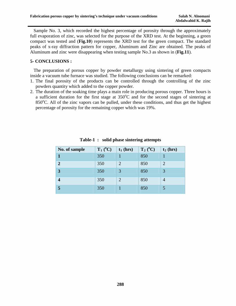
Sample No. 3, which recorded the highest percentage of porosity through the approximately full evaporation of zinc, was selected for the purpose of the XRD test. At the beginning, a green compact was tested and (Fig.10) represents the XRD test for the green compact. The standard peaks of x-ray diffraction pattern for copper, Aluminum and Zinc are obtained. The peaks of Aluminum and zinc were disappearing when testing sample No.3 as shown in (Fig.11).
5- CONCLUSIONS :
The preparation of porous copper by powder metallurgy using sintering of green compacts inside a vacuum tube furnace was studied. The following conclusions can be remarked: 1. The final porosity of the products can be controlled through the controlling of the zinc
powders quantity which added to the copper powder. 2. The duration of the soaking time plays a main role in producing porous copper. Three hours is
a sufficient duration for the first stage at 350oC and for the second stages of sintering at 850oC. All of the zinc vapors can be pulled, under these conditions, and thus get the highest percentage of porosity for the remaining copper which was 19%.
Table-1 : solid phase sintering attempts
No. of sample T1 (oC) t1 (hrs) T2 (oC) t2 (hrs) 1 350 1 850 1 2 350 2 850 2 3 350 3 850 3
4 350 2 850 4
5 350 1 850 5

Salah N. Alnomani The Iraqi Journal For Mechanical And Material Engineering, Vol.16, No3, 2016 Abdalwahid K. Rajih
289
Fig.1 : Solid phase sintered samples
Fig.2 : The tubular furnace of 1200 oC maximum temperature used in this study

Fabrication porous copper by sintering’s technique under vacuum conditions Salah N. Alnomani Abdalwahid K. Rajih
290
Fig.3 : heating cycles during sintering processes
Fig.4 : Hitachi TM3000 SEM

Salah N. Alnomani The Iraqi Journal For Mechanical And Material Engineering, Vol.16, No3, 2016 Abdalwahid K. Rajih
291
Fig.5 : Inel Equinox 3000 X-Ray Diffractometer used in this study.

Fabrication porous copper by sintering’s technique under vacuum conditions Salah N. Alnomani Abdalwahid K. Rajih
292
Fig.(6) : Selective SEM images for the five samples prepared.

Salah N. Alnomani The Iraqi Journal For Mechanical And Material Engineering, Vol.16, No3, 2016 Abdalwahid K. Rajih
293
Fig.(7) : A comparison between porosities of solid phase sintering samples
Fig.(8) : spectrum map EDS result for the main elements.
02468
101214161820
1 2 3 4 5
Poro
sity
%
Samples No.

Fabrication porous copper by sintering’s technique under vacuum conditions Salah N. Alnomani Abdalwahid K. Rajih
294
Fig.(9) : spectrum map EDS image for sample No.3

Salah N. Alnomani The Iraqi Journal For Mechanical And Material Engineering, Vol.16, No3, 2016 Abdalwahid K. Rajih
295
Fig.(10) : XRD test for the green compact
Fig.(11) : XRD test for sample No.3

Fabrication porous copper by sintering’s technique under vacuum conditions Salah N. Alnomani Abdalwahid K. Rajih
296
REFERENCES : Arisetty S., Prasad A.K. and Advani S.G., “Metal foams as flow field and gas diffusion layer in direct methanol fuel cells”, Journal of Power Sources, 165: 49-57, 2007.
Brady M.P., Weisbrod K., Zawodzinski C., Paulauskas I., Buchanan R.A., and Walker L.R., “Assessment of thermal nitridation to protect metal bipolar plates in polymer electrolyte membrane fuel cells”, Electrochemical and Solid-State Letters, 5(Nom. 11), A245-A247, 2002. Cunningham N., Guay D., Dodelet J.P., Meng Y., Hlil A.R., and Hay A.S., “New materials and procedures to protect metallic PEM fuel cell bipolar plates”, Journal -82 of the Electrochemical Society, 149(Nom. 7), A905-A911, 2002. El-Hadek M. and Kaytbay S., “Mechanical and Physical Characterization of Copper Foam”, Int J Mech Mater Des., vol. 4, pp. 63–69, 2008. Jeong H.K., Ryoung H.K. and Hyuk S.K., “Preparation of copper foam with 3-dimensionally interconnected spherical pore network by electrodeposition”, Department of Materials Science and Engineering, Korea Advanced Institute of Science and Technology, Electrochemistry Communications 10 (2008) 1148–1151. Kumar, A. and R.G. Reddy, “Polymer Electrolyte Membrane Fuel Cell with Metal Foam in the Gas Flow-Field of Bipolar/End Plates”, Journal of New Materials for Electrochemical Systems, 6: 231-236, 2003.
Lee S.J., Huang C.H., Lai J.J., and Chen Y.P., “Corrosion-resistant component for PEM fuel cells”, Journal of Power Sources, 131(Nom. 1-2), 162-168, 2004. Lin Yi-Wen, Chia-Cheng Tai, and Wen Sun, “Electrochemical Preparation of Porous Copper Surfaces in Zinc Chloride-1-ethyl-3-methyl Imidazolium Chloride Ionic Liquid”, Journal of The Electrochemical Society, 154 -6, Pages 316-321, 2007. Mahmoud M.M., “MANUFACTURING, TESTING, AND MODELING OF COPPER FOAMS”, G. J. P&A Sc and Tech., vol. 2, issue 2, 05 – 13, 2012. Parvanian A.M. and Panjepour M., “Development of Open Pore Copper Foams to Use as Bipolar Plates in Polymer Electrolyte Membrane Fuel Cell Stacks”, Iranica Journal of Energy & Environment 4 (2): 99-103, 2013. Shin H.C., Dong J., and Liu M., “Nano porous Structures Prepared by an Electrochemical Deposition Process”, Adv. Mater., Volume 15, Issue 19, Pages 1573–1660, 2003. Shudo T. and Suzuki K., “Performance improvement in direct methanol fuel cells using a highly porous corrosion-resisting stainless steel flow field”, International Journal of Hydrogen Energy, 33: 2850-2856, 2008.
Zhao Y.Y., Fung T., Zhang L. P., and Zhang F. L., "Lost carbonate sintering process for manufacturing metal foams", Scripta Materialia, vol. 52, pp. 295–298, 2005.


![EXPERIMENTAL AND THEORETICAL ANALYSIS OF SURGE …iqjmme.com/papers/jjou_paper_2016_51712459.pdf · .2004], presented the derivation of a compressor characteristic, and the experimental](https://static.fdocuments.net/doc/165x107/5d1a221488c993ad0d8d38e4/experimental-and-theoretical-analysis-of-surge-2004-presented-the-derivation.jpg)


