Fabrication and Erection 1994
17
Fabrication and Erection of Precast Concrete Segmental Boxes for Baldwin Bridge Mark J. Sofia, P.E. Project Manager Parsons Brinckerhoff Construction Services, Inc. Fort Myers, Florida Elie H. Homsi, P.E. Project Chief Engineer Perini Corporation Framingham, Massachusetts 36 The two parallel 11-span bridges over the Connecticut River between Old Saybrook and Old Lyme are segmental post- tensioned concrete structures using single cell precast concrete boxes. The total span of each bridge is 2522.5 ft (769 m). This article describes the precasting plant and the carefully engineered fabrication process, along with the erection system using a fully automated launching gantry to place the segmental boxes. The key to the project's success was knowledgeable and experienced firms in all aspects of design and construction of segmental concrete bridges. The successful bid for the bridge structures was 6 percent below the lowest steel alternate and the project was completed 12 months earlier than the specified contract time of 4 years. S ince May of 1993 , motorists traveling the northeastern corri- dor of Interstate 95 through New England have enjoyed the much needed luxury of the additional travel lanes provided by the completion of the Raymond E. Baldwin Bridge in Connecticut (see Fig. 1). The new structures that span the mouth of the pristine Connecticut River , between the towns of Old Saybrook and Old Lyme, have relieved some of the traf- fic congestion that plagues this travel- way, especially in the popular summer and colorful fall months. In January of 1990, the Connecticut Department of Transportation awarded the contract to build the new Baldwin Bridge to the Joint Venture of Perini- PCL-O&G. The Joint Venture pro- vided a low bid of $93.8 million to build the concrete alternate: a precast concrete segmental superstructure sup- ported on cast-in-place concrete piers. The Joint Venture was the only bidder to provide a price for the concrete al- ternate. All other bidders submitted a price for the supposedly more popular and economical steel girder alternate (see Table 1). The bridge building industry, along with the Connecticut Department of Transportation, was very surprised at the outcome of the bid. In addition, the Department was a little apprehensive about having a precast segmental con- PCI JOURNAL
-
Upload
norhalim-idrris -
Category
Documents
-
view
63 -
download
1
description
Fabrication of segmental box girder at casting yard and the launching method.
Transcript of Fabrication and Erection 1994

Fabrication and Erection of Precast Concrete Segmental Boxes for Baldwin Bridge
Mark J. Sofia, P.E. Project Manager Parsons Brinckerhoff Construction Services, Inc. Fort Myers, Florida
Elie H. Homsi, P.E. Project Chief Engineer Perini Corporation Framingham, Massachusetts
36
The two parallel 11-span bridges over the Connecticut River between Old Saybrook and Old Lyme are segmental posttensioned concrete structures using single cell precast concrete boxes. The total span of each bridge is 2522.5 ft (769 m). This article describes the precasting plant and the carefully engineered fabrication process, along with the erection system using a fully automated launching gantry to place the segmental boxes. The key to the project's success was knowledgeable and experienced firms in all aspects of design and construction of segmental concrete bridges. The successful bid for the bridge structures was 6 percent below the lowest steel alternate and the project was completed 12 months earlier than the specified contract time of 4 years.
Since May of 1993 , motorists traveling the northeastern corridor of Interstate 95 through
New England have enjoyed the much needed luxury of the additional travel lanes provided by the completion of the Raymond E . Baldwin Bridge in Connecticut (see Fig. 1) . The new structures that span the mouth of the pristine Connecticut River, between the towns of Old Saybrook and Old Lyme, have relieved some of the traffic congestion that plagues this travelway, especially in the popular summer and colorful fall months.
In January of 1990, the Connecticut Department of Transportation awarded the contract to build the new Baldwin
Bridge to the Joint Venture of PeriniPCL-O&G. The Joint Venture provided a low bid of $93.8 million to build the concrete alternate: a precast concrete segmental superstructure supported on cast-in-place concrete piers. The Joint Venture was the only bidder to provide a price for the concrete alternate. All other bidders submitted a price for the supposedly more popular and economical steel girder alternate (see Table 1).
The bridge building industry, along with the Connecticut Department of Transportation, was very surprised at the outcome of the bid. In addition, the Department was a little apprehensive about having a precast segmental con-
PCI JOURNAL

Fig. 1. Overall view of Raymond E. Baldwin Bridge nearing completion.
Table 1. Bids for the Baldwin Bridge project. ciates. The Department also retained the bridge designer, Parsons Brinckerhoff Quade and Douglas , Hartford, Connecticut, for post-design services and on-site technical assistance.
Contractor Bid (in millions) Alternate -
Perini-PCL-O&G $ 93.8 Segmental concrete - ~
Cianbro/Massman $ 99.9 Steel girder -
Kiewit Eastern/ $ 100.8 Steel girder
Guy F. Atkinson
Tomasso $105.7 Steel girder PROJECT DETAILS
crete structure built in their state since, at the time, segmental structures were receiving mixed reviews from trade magazines and skeptical contractors.
To assist the Department in managing the construction of this state-of-
" " " l 177.5 ' 177.5 ' 177.5 l . 240'
Fig. 2. Profile of Baldwin Bridge.
November-December 1994
the-art structure, they awarded a construction engineering and inspection contract to a joint venture of Parsons Brinckerhoff Construction Services, Herndon, Virginia, and a local engineering and survey firm , L-C & Asso-
Soon after notice to proceed had been given, the Joint Venture informed the owner of their intention to submit an early completion schedule and finish the project 12 months ahead of the contracted duration of 48 months. This accelerated construction schedule was
1500' VERTICAL CURVE
+3% -3%
~~:-··------ ·-·-Jf.----------- --J : __ ; . ·J:I:· ··· ··········;:[-. ····· ··· · .... _[_ .. ... .... --·
~- ~ ' ...
1 f 6
l 240'
~ - ~ '
~-; ~-; ~-:
F7
240'
NAVIGATION SPAN
f 8 f 9
240' 275'
p 0
275' Jl2
240'
37

+100 +100
A ~ }.
"'~ ~c:zs:J/
PIER SHAFT PIER SHAFT
r-MSL
90.0
-PEDESTAL BASE
STEEL / CONCRETE FOOTING
COFFERDAM I - ·- - - _-;-:-,.. .....
I I~JLIEI ~Ell 1 '---
F ROC]
lJ
TOP 0
---100
Fig. 3. Typical piers with the deck segments in place.
to be supported and made possible by a modification to the erection method shown in the contract plans.
The proposed modification called for the balanced cantilever erection to be performed using a fully automated overhead erection truss to place the precast concrete segments, instead of the modified beam and winch method shown in the contract documents. The overhead erection truss would erect the westbound structure first and then it would be transported back over the completed bridge and used again to erect the eastbound structure.
Each bridge is an 11-span, continuous unit consisting of 244 constant depth precast concrete box girder segments. Typical span lengths are 245 ft (75 m); non-typical spans range from 177 ft 6 in. (54 m) at the west abutment to 275 ft (84 m) at Spans 8 and 9 on the east end of the bridge (see Fig. 2). The total span of each bridge is 2522.5 ft (769 m).
The bridge designer minimized the number of different types of segments to four: pier (20), abutment (4), Type "B" (96), Type "A" (375). The Type "B" segments are erected adjacent to the pier and abutment segments. All
38
draped cantilever tendons pass through the pier segment diaphragms and anchor in the tendon deviation blocks at the lower comer of the Type "B" segments (see Fig. 3). The remainder of the cantilevers comprise varying numbers of Type "A" segments. These segments are connected to the cantilevers with top slab cantilever tendons and with top and bottom slab continuity tendons.
Box Girder Segments
The precast roadway segments for the Baldwin Bridge are the second largest single cell box girder segments cast in the United States. The trapezoidal cross section of the seg ment is stiffened transversely by inclined precast concrete struts. The designer chose to use the inclined struts instead of multiple vertical web walls because it was considered more structurally efficient and made the segment lighter and less difficult to fabricate.
Each segment is 11 ft 8 3/s in . (3 .6 m) in height and 74 ft 8 in . (22.8 m) in width for the eastbound bridge and 83 ft 9 in. (26.3 m) for the westbound bridge (see Fig. 4). The addition a l
-MSL..,O.O
STEEL COFFERDAM
- L SAND LINE
--100
width on the westbound segment provides space for an 8 ft (2.4 m) wide pedestrian walkway and bicycle path. A typical segment is 10ft 7 in. (3.2 m) in length with the pier and abutment segments being 6 ft 2 in. and 7 ft I in . (1.9 and 2.2 m) in length, respectively. The segment weights vary from 140 tons (127 t) for the Type "A" segments to 150 tons (136 t) for the pier and abutment units.
The thickness of the top slab is 8 in. (203 mm) within the box and 9 in . (229 mm) on the wings. The bottom slab is 8 in. (203 mm) along the centerline of the box and increases to 14 in. (356 mm) at the web walls to allow space for the internal longitudinal tendons. The bottom slab thickness increases to a constant depth of 21 in. (533 mm) at the Type "B" segments. This additional thickness is needed to resist the large compressive forces produced during balanced cantilever erection. To maintain similar weights between seg ments, a portion of the Type "B" segment bottom slab was poured after erection .
Multiple shear keys are utilized on the web wall face along with individ-
PCI JOURNAL

861' -0" WESTBOUND 7~ ' -II" EASTBOUND
I~ 12· 12· 12· 12· 12· 12· SDWK. SHDR. LANE LANE LANE LANE SHOR.
~ ~ .~.
i i [ ,~. , ~~ ~ ~ ~ c~ , c~~ ,~. ,
~es/r ~~. -2"
CANTILEVER I 3N" I
Fig. 4. Typical cross section of the superstructure.
Fig. 5. Casting yard layout.
ual shear and alignment keys along the top and bottom slabs. The web thickness is a constant 23 in. (584 mm) for both the pier, abutment, and Type "B" segments. The web thickness for Type "A" segments varies from 18 in. (457 mm) at the top to 12 in. (305 mm) at the bottom slab. Diaphragms and inclined struts of the pier and abutment segments are typically 4ft (1.2 m) wide and centered over the centerline of the bearings.
The top slabs of all segments are post-tensioned in the transverse direction with four-strand tendons. These tendon s were stressed at a minimum concrete strength of 2500 psi (17 MPa). Because of this, and due to the high bursting stresses at the anchorage location, precast concrete
November-December 1994
edge beams were used at each end of the top slab to provide 5500 psi (38 MPa) concrete strength in this area. This feature was also used successfully in the Sun shine Skyway Bridge over Tampa Bay, Florida.
Typically , four-strand loop tendons were used to post-tension the web and bottom slab areas. Due to the extreme curvature of these tendons , they were stressed simultaneously from both ends. The bottom slab was additionally post-tensioned along its centerline with a single multi-strand tendon. A transverse rib was provided on the bottom slab to supply space for this tendon. The diaphragm section and struts of the pier and abutment units are also posttensioned in the transverse direction with multiple multi-strand tendons.
All post-tensioning tendons consisted of 0 .5 in . (13 mm) diameter, 270 ksi (1860 MPa), low relaxation strand. The contractor chose to use 0.5 in. (13 mm) diameter strand rather than the 0.6 in. (15 mm) diameter type that was specified in the contract plans. Corrugated galvanized metal ducts were also used for all longitudinal and transverse multi-strand tendons. This semi-rigid duct was preferable to the less expensive polyethylene duct material because it was less difficult to install and achieved more accurate tendon profiles.
Casting Yard
After carefully studying their options , the contractor secured a 20-acre (8 . 1 ha) parcel of land to set up a casting facility (see Fig. 5). The casting yard was approximately 1.5 miles (2.4 km) from the bridge site and conveniently located between the bridge site and the local concrete producer's facility. This location made it more economical for the contractor to purchase ready-mix concrete instead of setting up a batch plant. Within 6 months of notice to proceed, a 14-acre (5.7 ha) section of the wooded lot had been cleared and the contractor began installing utilities and foundation s, and assembling the necessary casting equipment and formwork .
Because there were three types of segments to fabricate, the contractor used three segment assembly lines . The assembly lines were set up adjacent to one another in a north-south
39

Fig. 6. Short-line match casting of segments.
Fig. 7. Segments in storage; total storage capacity of 180 units.
Fig. 8. 300-ton (272 t) travel crane.
40
orientation. Each production line comprised one set of custom made forms supported by two reinforcing steel jigs/assembly frames .
Situated between the casting beds and the reinforcing steel fabrication area was a mobile, rail-mounted tower crane. This crane provided support to all three production lines. It was used to handle all materials, install the prefabricated reinforcing steel cages, and relocate the segment soffit forms in each casting bed. The tower crane could handle a maximum load of 15 tons (14 t) operating on a 100 ft (30m) radius.
As segments were produced by the short-line casting method, they were rolled to the end of the production line and hauled into storage (see Fig. 6). The original storage area provided enough capacity to store 130 segments (see Fig. 7).
The contractor held a 5-acre (2.0 ha) section of the yard in reserve in case there were delays in the erection process. This proved to be a very prudent plan on the contractor's part. In July of 1991 , the initial storage area was full and the erection process had not yet begun. The contractor then chose to exercise his option and clear the remainder of the available land, which provided storage capacity for 50 additional segments. If it were not for this additional storage area, the production of segments would have been discontinued until the erection process began, 3 months later.
Segments were moved from casting bed to casting bed and hauled into storage with a custom made 300-ton (272 t) Shuttle Lift travel crane (see Fig. 8). It was equipped with a special lifting frame that was designed to allow the travel lift to straddle one segment while placing or lifting another segment adjacent to it. It was important to have this ability so that the maximum percentage of available storage area could be utilized for segment storage rather than for access runways.
Production Area All reinforcing steel and post
tensioning ducts for each Type "A" and Type "B" segment were installed in prefabrication jigs (see Fig. 9). Because the reinforcing steel and post-
PCI JOURNAL

Fig. 9. Typical reinforcing steel layout jig .
Fig. 10. Prefabricated steel cage being lifted into casting machine.
tensioning items were tied in the formwork for the pier and abutment segments, three jigs were initially available for use for the Type "A" and Type "B" segments. Once all the pier and abutment segments had been cast, the casting form was converted to produce Type " A" segments, with each form then being supported by two jigs.
The use of multiple jigs took fabrication of the reinforcing steel cages off the critical path and provided for a small amount of lag time between the fabrication of the cage and the need to install it in the formwork. This lag allowed for much needed contingency time for production related problems, such as steel fabrication errors and
November-December 1994
material delivery delays. Each jig was made of various stan
dard steel shapes, with plywood faces to accurately simulate the exterior dimensions and cross section of a segment. A wooden bulkhead simulated the segment cross section and was marked accurately with the typical locations of longitudinal post-tensioning anchorages and duct locations. This allowed the required embedded items to be accurately placed in the jig within acceptable field tolerances. It was imperative that as much work as possible be done in the prefabrication area so that critical production time in the formwork area could be used strictly for form work and segment setup.
The precast concrete struts and edge beams were the first items to be placed in the jigs. A crew of two carpenters placed these items, and set the required post-tensioning anchorages and prepared the jig area for the steel tying crew. Typically, a crew of six ironworkers tied 7000 to 12,000 lbs (4080 to 5440 kg) of epoxy coated reinforcing steel in an 8 to 10-hour period.
A three-man ironworker crew installed the transverse post-tensioning ducts and tendons, along with all the longitudinal post-tensioning ducts, concurrently with the tying of the reinforcing steel. AIL semi-rigid corrugated metal ducts that required curvature were bent to the desired geometry in the jig area prior to placement. Templates were laid out on the concrete slab in the steel tying area to allow for accurate bending.
Once the reinforcing steel cage was completed, it was lifted in its entirety from the jig area to the casting bed by the traveling tower crane (see Fig. 10). The contractor had a special lifting frame designed and fabricated to rigidly support and maintain the integrity of the steel cage during transportation. After a steel cage was removed, the process would be repeated begi nning with clean-up of the area and installation of the precast concrete struts and edge beams. The entire process of fabrication to installation was completed within a 12-hour work period.
Automated Formwork
Each short-line casting bed was outfitted with a custom made set of fully automated steel forms. The formwork was designed by Concrete Forms Consultants, Hawley, Pennsylvania, and was fabricated by Transfab, Huntington, West Virginia. Each set of forms consisted of three movable soffits, a fixed bulkhead, adjustable wing forms , and a retractable inner core form.
The contractor procured three soffit forms in order to take the removal of cast segments to storage off the critical path of production. Each soffit was fully equipped with hydraulic jacks to support and manipulate the match-cast segment to its proper orientation in the casting bed. The soffit forms were supported on rai l-mounted Hillman
41

Fig. 11. Setting forms for the match-casting operation.
Fig. 12. Concrete placement with a mobile pumping unit; curing blankets provide steam curing enclosure.
rollers for smooth and si mplified movement. A front end loader pulled the segment in and out of its matchcast position.
The steel bulkhead was rigidly supported and fixed to a concrete foundation. After the initial setup, no adjustments to the bulkhead were necessary. The segment wing forms were pinned at the bottom, near the soffit area, and were made adjustable at the rear by use of hydraulic jacks. Only vertical movement of the side forms was necessary for stripping of the unit. The inner form was supported in cantilever by a movable steel support frame.
The support frame was also moun-
42
ted on Hillman rollers and was outfitted with hydraulic jacks to raise and lower the inner core form prior to installing or retracting the assembly. Due to space limitations, the inner core support frame was manipulated into position by a hydraulic push-pull cylinder mounted under the assembly frame with the piston rod anchored to the concrete foundation. This proved to be a very effective and economical way to move the inner core system in and out of the casting position .
The inner core forms were also outfitted with hydraulic jacks to fully automate the placement and stripping operations. All formwork hydraulics were
operated from a centrally located control unit. Miscellaneous formwork for the bottom slab transverse rib and local areas around the precast strut connections, at the top slab and at deviation block areas, was placed by hand.
The speed of formwork manipulation justified the additional expense for the extensive hydraulic packages. A typical precast segment was stripped and pulled out of the casting position within a 2-hour period, usually between 6:30 a.m. and 8:30 a.m., the morning after the pour. Setup of the formwork and the match-cast unit was accomplished in a 3 to 4-hour period, usually between 10:00 a.m. and 2:00 p.m., the day of the pour.
Of great importance to the aesthetics of a segmental structure is the fit between the wing form and the underside of the wing and inclined web of the match-cast segment. Proper fit prevents unsightly offsets from occurring between segment joints. This set of formwork was manufactured well and provided a tight fit between the formwork and the match-cast segment.
PRODUCTION As stated previously, all segments,
with the exception of the pier and abutment segments, were match cast by the short-line casting method (see Fig. 11). After a pier or abutment segment was cast, the segment was transfened over to the adjacent casting bed to match cast each Type "B" segment. Once one direction of the Type "B" cantilevers was complete, the pier segment was lifted and rotated to begin casting the other side of the cantilever. Following the casting of the last Type "B" segment in the cantilever, this unit was transferred over to the adjacent casting line to begin match casting the Type "A" segments, which made up the remainder of each cantilever.
Pier segments were generally cast on a 10-working day cycle. At the beginning of casting, the first three or four pier segments were produced in 6 to 7 working days to allow the casting process to begin in the "A" and "B" segment production lines . The "B" segments were produced on a 2 and 3-day cycle, and the "A" segments were produced on a daily basis. Working a
PCI JOURNAL

5-day work week, the contractor routinely produced 20 "A" segments, 8 "B" segments, and 2 pier segments, for a total of 30 segments per month.
The contractor started casting segments in November 1990, during what local Connecticut residents called a mild winter. The production "learning curve" lasted approximately 6 weeks, which was fairly short for casting large segments with this type of cross section. The short duration of the learning curve was attributable to an experienced supervisory staff, quick learning by local union trades, and a production system that was laid out well and provided for maximum efficiency.
Concrete Placement Concrete was delivered to the cast
ing yard in I 0 cu yd (7 .6 m3) front dis
charge ready mix trucks by the local concrete producer. After reviewing their options, the contractor chose to pump concrete instead of setting up a conveyor system that would have served all three casting beds. All concrete was placed with a Schwing pump truck (see Fig. 12).
Concrete was first placed in the lower corner of a segment and the strut block area (tendon deviation block), followed by the bottom slab and transverse rib. At this time, the seven-man concrete crew moved on top of the segment to pour both web walls.
This sequence allowed the bottom slab and lower web walls to setup slightly and help support the concrete pumped into the web walls that were on a 75-degree incline. Once the web walls were topped out, the deck was placed from one end to the other. The deck surface was leveled off with a manually operated longitudinal screed. The deck then received a bull float fmish.
A smooth surface finish was specified because the surface overlay began with a membrane type asphalt liner that required a smooth underlying surface . All concrete was consolidated with manually operated internal vibrators; no external vibration was necessary. From start to finish , the concrete placement was accomplished in a 2112 to 3-hour period.
The concrete mix design consisted of 705 lbs (418 kg) of Type I cement, 1800 lbs (1068 kg) of coarse aggre-
November-December 1994
Fig. 13. Precast concrete segment loaded on 96-wheel trailer for transport to site.
gates, 1295 lbs (768 kg) of sand, and 279 lbs (166 kg) of water per cu yd (m 3
). Admixtures included 5.5 oz . (0.16 liters) of air entrainment, 21.2 oz. (0.63 liters) of set retarder and 106 oz. (3.13 liters) of WRDA 19 high range water reducer. All admixtures were introduced into the mix at the batch plant. The target slump for this mix was 6.5 in. ± 1.5 in. (165 mm ±38 mm). The use of the high range water reducer allowed for ease of placement, less vibration during consolidation, and lower water-cement ratio to help ensure a high early strength concrete.
The concrete was cured with low pressure steam to guarantee a minimum 2500 psi (17 MPa) strength at 6:30 a.m., the morning following the pour. Concrete strengths of 3700 psi (25.5 MPa) were actually achieved after a relatively short steam cycle that included a 3-hour preheat period to achieve initial set, followed by a gradual rise to a maximum temperature of 100° to l20°F (38° to 49°C) that was maintained for approximately 6 hours.
The steam enclosure consisted of concrete curing blankets that were hung around the casting form and match-cast unit to completely enclose both units (see Fig. 12). Although this was a crude steam enclosure, it proved to be very effective and able to maintain a consistent curing environment. Steam curing of both the new and match-cast units was required and helped prevent differential volume changes from occurring between seg-
ments , thus ensuring a proper matchcast relationship.
During the winter months, the formwork and reinforcement were preheated by steaming and supplemented during the casting with 1,000,000 Btu (1 ,056,000 kj) space heaters to maintain the casting area above 50°F (10°C). Following the overnight curing cycle, typical "A" and "B" segments were completely exposed to ambient temperatures. In the winter months these temperatures, at times, were well below freezing. No cracking from " thermal shock" was experi enced on these segments. This was most likely due to the relatively small thicknesses of the concrete sections on the typical "A" and "B" segments. Because of their thick diaphragm sections , pier and abutment segments remained partially covered with concrete curing blankets for 2 to 3 days. This provided the necessary protection to the 4 ft (1.2 m) thick diaphragms and helped minimize any cracking due to large temperature differentials .
TRANSPORTATION AND ERECTION
Segment Transport
The 300-ton (272 t) Shuttle Lift was used to load the segments on a special 12-axle, 96-wheel hydraulic trailer chosen by the Joint Venture to transport the segments from the casting yard to the erection site (see Fig. 13).
43

a
b
PIER 5 PIER 6
c
PIER 5 PIER 6
d
PIER 5 PIER 6
Fig. 14. (a) Launching gantry for placing segmental boxes; (b) to (d) Steps to move gantry to cantilever erection position.
44 PCI JOURNAL
e
PIER 5 PIER 6 PIER 7
f
PIER 6 PIER 7
9
PIER 6 PIER 7
h
PIER 6 PIER 7
Fig. 14 (cont.) . Launching gantry for placing segmental boxes; (e) to (h) Steps to move gantry to cantilever erection position.
November-December 1994 45
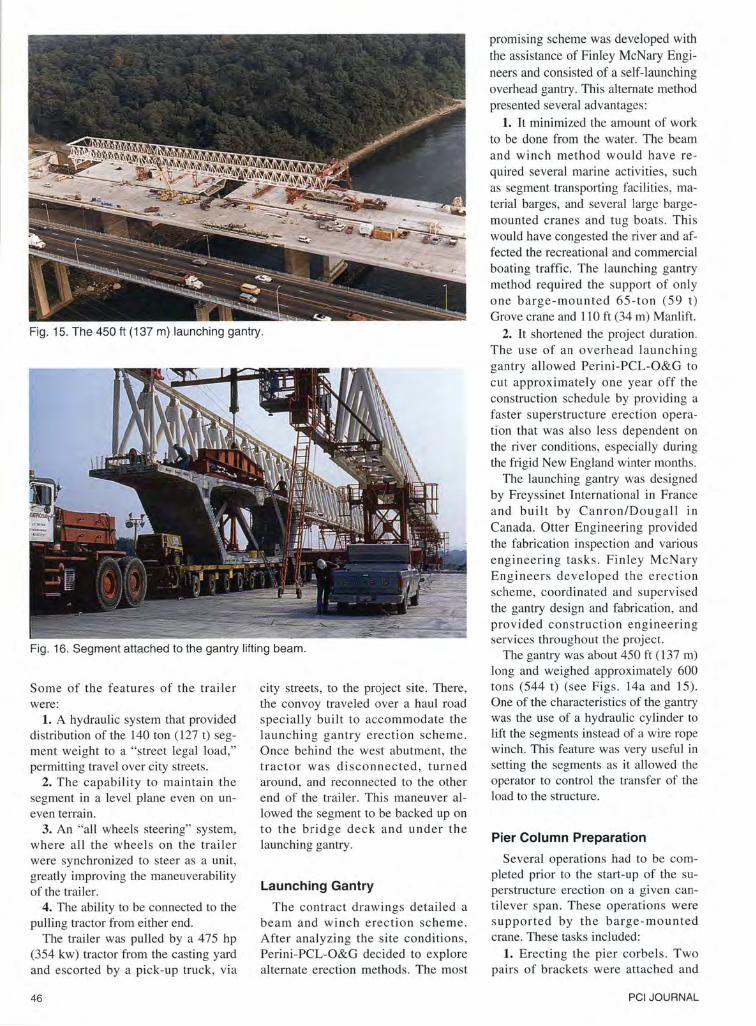
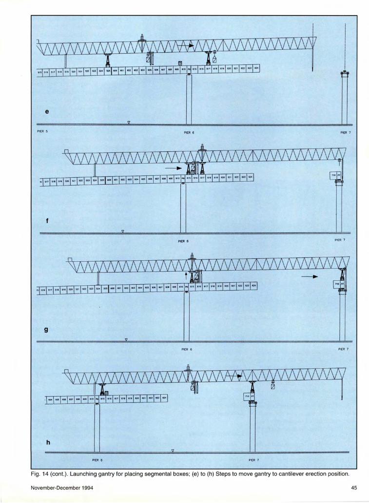
Fig. 15. The 450ft (137 m) launching gantry.
Fig . 16. Segment attached to the gantry lifting beam.
Some of the features of the trailer were:
1. A hydraulic system that provided distribution of the 140 ton (127 t) segment weight to a "street legal load," permitting travel over city streets.
2. The capability to maintain the segment in a level plane even on uneven terrain.
3. An "all wheels steering" system, where all the wheels on the trailer were synchronized to steer as a unit, greatly improving the maneuverability of the trailer.
4. The ability to be connected to the pulling tractor from either end.
The trailer was pulled by a 475 hp (354 kw) tractor from the casting yard and escorted by a pick-up truck, via
46
city streets, to the project site. There, the convoy traveled over a haul road specially built to accommodate the launching gantry erection scheme. Once behind the west abutment, the tractor was disconnected , turned around, and reconnected to the other end of the trailer. This maneuver allowed the segment to be backed up on to the bridge deck and under the launching gantry.
Launching Gantry
The contract drawings detailed a beam and winch erection scheme. After analyzing the site conditions, Perini-PCL-O&G decided to explore alternate erection methods. The most
promising scheme was developed with the assistance of Finley McNary Engineers and consisted of a self-launching overhead gantry. This alternate method presented several advantages:
1. It minimized the amount of work to be done from the water. The beam and winch method would have required several marine activities , such as segment transporting facilities, material barges, and several large bargemounted cranes and tug boats. This would have congested the river and affected the recreational and commercial boating traffic. The launching gantry method required the support of only one barge-mounted 65-ton (59 t) Grove crane and 110 ft (34 m) Manlift.
2. It shortened the project duration. The use of an overhead launching gantry allowed Perini-PCL-O&G to cut approximately one year off the construction schedule by providing a faster superstructure erection operation that was also less dependent on the river conditions, especially during the frigid New England winter months.
The launching gantry was designed by Freyssinet International in France and built by Canron/Dougall in Canada. Otter Engineering provided the fabrication inspection and various engineering tasks . Finley McNary Engineers developed the erection scheme, coordinated and supervised the gantry design and fabrication , and provided construction engineering services throughout the project.
The gantry was about 450ft (137m) long and weighed approximately 600 tons (544 t) (see Figs. 14a and 15). One of the characteristics of the gantry was the use of a hydraulic cylinder to lift the segments instead of a wire rope winch. This feature was very useful in setting the segments as it allowed the operator to control the transfer of the load to the structure.
Pier Column Preparation
Several operations had to be completed prior to the start-up of the superstructure erection on a given cantilever span . These operations were supported by the barge-mounted crane. These tasks included:
1. Erecting the pier corbels. Two pairs of brackets were attached and
PCI JOURNAL
stressed to the top of each pier (see Fig. 17). Each bracket supported a hydraulic jack. These corbels were used to support the gantry in the pier segment erection position, and to help balance the cantilever during the ini
tial construction stages. The corbels also served as a support for the platform around the pier top.
2. Stressing the pier caps. This step was required by the bridge design to minimize the size of the caps and to sustain the high bursting forces from the bridge weight.
3. Setting and grouting the bridge bearings. To speed up the segment erection process, the Joint Venture decided to set and grout the bearings ahead of segment erection in order to remove these activities from the critical path. An accurate "as built" survey of the embedded plates in the pier segment was used to calculate the coordinates of the bearings on top of the pier.
Launching the Gantry to the Next Pier
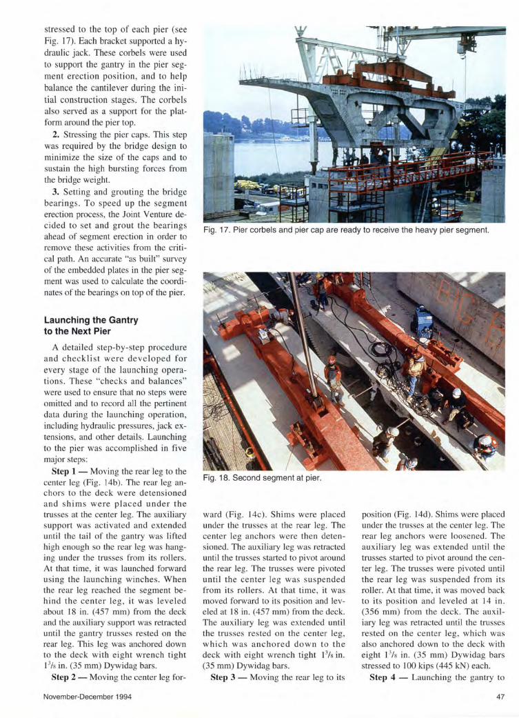
A detailed step-by-step procedure and checklist were developed for every stage of the launching operations. These "checks and balances" were used to ensure that no steps were omitted and to record all the pertinent data during the launching operation, including hydraulic pressures, jack extensions, and other detail~. Launching to the pier was accomplished in five major steps:
Step 1 - Moving the rear leg to the center leg (Fig. 14b). The rear leg anchors to the deck were detensioned and shims were placed under the trusses at the center leg. The auxiliary support was activated and extended until the tail of the gantry was lifted high enough so the rear leg was hanging under the trusses from its rollers . At that time, it was launched forward using the launching winches. When the rear leg reached the segment behind the center leg, it was leveled about 18 in. (457 mm) from the deck and the auxiliary support was retracted until the gantry trusses rested on the rear leg. This leg was anchored down to the deck with eight wrench tight 13/s in. (35 mm) Dywidag bars.
Step 2 - Moving the center leg for-
November-December 1994
Fig. 17. Pier corbels and pier cap are ready to receive the heavy pier segment.
Fig. 18. Second segment at pier.
ward (Fig. 14c). Shims were placed under the trusses at the rear leg. The center leg anchors were then detensioned. The auxiliary leg was retracted until the trusses started to pivot around the rear leg. The trusses were pivoted until the center leg was suspended from its rollers. At that time, it was moved forward to its position and leveled at 18 in. (457 mm) from the deck. The auxiliary leg was extended until the trusses rested on the center leg, which was anchored down to the deck with eight wrench tight 13/s in. (35 mm) Dywidag bars.
Step 3 - Moving the rear leg to its
position (Fig. 14d). Shims were placed under the trusses at the center leg. The rear leg anchors were loosened. The auxiliary leg was extended until the trusses started to pivot around the center leg. The trusses were pivoted until the rear leg was suspended from its roller. At that time, it was moved back to its position and leveled at 14 in. (356 mm) from the deck. The auxiliary leg was retracted until the trusses rested on the center leg, which was also anchored down to the deck with eight 13/s in. (35 mm) Dywidag bars stressed to 100 kips (445 kN) each.
Step 4 - Launching the gantry to
47

Fig. 19. Connecting the erection posttensioning bars.
the pier (Fig. 14e). The auxiliary leg was completely retracted. The shims were removed from under the trusses and the trusses were set on rollers. The gantry was launched forward toward the next pier.
Step 5 - Activating the front leg. When the front leg was on top of the upstation corbel of the pier, it was extended and locked to the corbel. The pressure in the front leg jacks was incrementally increased until about 100 kips (445 kN) were transferred to the corbels. At that stage, the jacks were secured and shims under the trusses were installed at the rear leg. For spans shorter than 240 ft (73 m), in Step 1 the rear leg was moved to its final position and Steps 2 and 3 were omitted.
Erecting the First Two Segments (The Pier Table)
After positioning the pier segment under the tail of the gantry , the segment was connected to the lifting beam by eight 13/s in. (35 mm) Dywidag bars (see Fig. 16). The bars passed through slotted holes in the lifting beam and the longitudinal slope of the segment was preset by varying the position of the bars in the slotted holes. The segment was then lifted and transversely leveled using the transverse leveling jack on the lifting beam.
48
Fig. 20. Applying epoxy adhesive to the joints between segments.
Fig. 21 . Second segment post-tensioned to pier segment.
The segment was raised and carried to the pier where it was rotated 90 degrees and lowered on top of the bearings (see Fig. 17). A survey crew was used to guide and verify the position of the segment. The bearings were bolted to the embedded plate in the pier segment.
After completely transferring the load to the bearing, the pier segment was stressed down to the pier and the lifting trolley was disconnected and traveled back to the tail of the gantry to pick up the next segment.
The second segment was brought in , lowered and positioned about 2 ft (610 mm) from its final position on
the downstation side of the pier (see Fig. 18). At that point, several operations took place simultaneously:
1. Connecting the erection post-tensioning bars (see Fig. 19). Eight 11
/ 4 in. (32 mm) Dywidag bars were used to apply the erection post-tensioning forces needed until the permanent post-tensioning could be applied. One crew connected the post-tensioning bars between the segments, installed the bearing plates, nuts , and jacking chairs, and connected the jacks to the hydraulic control system.
2. Installing several "come alongs" in order to guide the segment.
3. Mixing and applying the epoxy
PCI JOURNAL

adhesive (see Fig. 20). About 10 gal. (38 liters) of Sikadur 31 segmenta l bridge adhesive was used in the joints. The main purposes of the epoxy were to seal and lubricate the joint and to even ly distribute the stresses across the face of the segments. The epoxy was mixed with a handheld mixing drill and a 1/s in. (6 mm) coat was applied by hand to one face of the segment. Generous amounts of epoxy were placed around the permanent post-tensioning ducts to e nsure a proper seal and prevent leakage during the grouting operations.
The gantry operator and the "come along" crew brought the segment to its final position. As the two segments made contact, the hydraulic jacks were connected and act ivated to start pulling on the erection post-tensioning bars. The gantry operator maintained the pressure in the hydraulic cylinder by extending or retracting it.
This operation ensured that no excessive loads were transferred to the deck, minimized shear key spalling, and guaranteed that the weight of the segment was sti ll fu ll y carried by the gantry . The pressure on the erection post-tensioning jacks was brought up incrementally while checking the proper closure of the joint. A sizable bead of epoxy squeezed out all around the joint, indicating that the joint was properly sealed.
After the erection post-tensioning bars were locked in place and a random lift-off check was performed, the j acks between the segment and the corbels were extended to touch the bottom of the segment and pressurized to 500 psi (3.4 MPa) (see Fig. 21). At this point, the gantry operator started to release the load incrementally. After a final check of the joint, the erection post-ten s ioning jacks were removed.
Immediately after disconnecting the lifting beam, all the empty permanent post-tensioning ducts were swabbed in order to clean and flatten the bead of epoxy that formed inside the duct (see Fig. 22). If not cleaned, this bead would have reduced the effective diameter of the duct and caused serious problems during installation of the tendons and possible tendon blockage during the grouti ng operations.
November-December 1994
Fig . 22. Cleaning out post-tensioning ducts.
Fig. 23. Pier table complete and segments for cantilevers moving out from pier.
49

Fig. 24. Inserting permanent post-tensioning tendons into ducts.
Fig . 25. Cantilever erection by alternately placing segments left and right of the pier.
Fig. 26. Gantry stabilizers are connected to the deck.
50
Fig. 23 shows a pier with the pier segment and adjacent segments in place, and the next segment being moved longitudinally over the counterweight. After a number of segments were placed, the gantry was prepared for launching to the cantilever erection position from which the remainder of the span was erected.
Launching the Gantry to the Cantilever Erection Position
Launching the gantry to the cantilever erection position was accomplished in three major steps:
Step 6 - Moving the rear leg to the center leg (Fig. 14f). The rear leg was moved forward as described in Step 1 and anchored to the deck by stressing the Dywidag bars.
Step 7 - Moving the center leg to the pier segment (Fig. 14g). The center leg anchors were loosened. The front leg was activated and extended until the trusses started to pivot on the rear leg and the center leg became suspended from the trusses. At that time, it was moved forward to the pier segment and leveled 12 in. (305 mm) from the deck. The front leg was retracted until the trusses rested on the center leg, which was anchored down to the deck by stressing the Dywidag bars.
Step 8 - Launching the trusses to the cantilever position (Fig. 14h). The shims were removed from under the trusses at the rear leg and the trusses were set on rollers . The trusses were launched forward until the king post was above the center leg. Special shims were installed under the trusses at the center leg and the gantry was ready to erect the remaining segments in the cantilever.
Typical Balanced Cantilever Segment Erection
The first segment upstation of the pier was brought in and erected in the same manner as the downstation segment. The permanent post-tensioning tendons, which were prefabricated on the bridge deck , were pulled into the duct (see Fig. 24). The VSL posttensioning system was used to stress the multi-strand tendons.
The segment erection continued (Fig. 25) by alternating the segments be-
PCI JOURNAL

tween the downstation and upstation of the pier with some variations, such as :
1. A 125-ton ( 113 t) counterweight was placed on the deck after erection of the th ird segme nt. Thi s counterwe ight was used to help balance the dec k in the unbalanced stages. The counterweight was moved three times to varying locations during a typical span construction.
2. After erecting two segments on either side of the pier, the launching gantry stabilizers were connected to the deck to stabilize the superstructure du ring the unbalanced co nstructi o n stages (see Fig. 26). The jacks on the corbels were released at that time. The stabili zers were moved several times during a typical span construction.
3. Tn addition to the top slab cantil ever te ndons, some of the lo nger spans req ui red the in stall a ti o n a nd stress ing of draped te ndo ns. These te ndo ns were anc ho red in the strut blocks and were deviated in the pier segment diaphragm.
4. When about half of the segments were erected, the elevation of the leading edge of the cantilever was checked and adjusted as needed . The adjustment was done by pi voting the deck around the bridge bearings with the li fting trolley and the stab ilizing arms of the gantry.
After all the segments were placed, the geometry of the deck was checked and the upstation of the prev ious span was checked against the dow nstati on of the new span. The e levati o n was adj usted by pi voting the deck whil e the alignment was adjusted using specia l beams that were clamped to the deck at the c losure gap and that a llowed the deck to be rotated on the fixed bearing at the pier (see Fig. 27). Only one span requ ired an alignment adjustment.
The c losure pour between the two cantilevers was formed and poured. After the concrete had reach 2500 psi ( 17 MPa), stress ing of the continui ty tendons in the bottom slab took place. These tendons were anchored in the strut blocks and connected the newly erected span to the previous span.
The gantry was prepared fo r launching to the next span and the deck was resurveyed. The new data were used to pos ition the bearings on the next pier
November-December 1994
Fig. 27. Final adjustments at the closure gap.
Fig. 28. Grouting operations on a completed span .
Fig . 29. Final segments being placed in last span of new, parallel segmental bridges; existing bridge is in foreground.
51
cap. Grouting operations started after the gantry was launched (see Fig. 28).
The remaining spans (see Figs. 29 and 30) were erected the same way, except for the four abutment spans that were conventionally erected on falsework. A typical span was erected in 3 weeks on single 12-hour shifts or in 2 weeks on double 12-hour sh ifts.
After erecting the westbound bridge, the gantry was raised and braced on special trailers supplied by Williams Crane and Rigging, and brought back over the completed bridge deck to be repositioned on the eastbound bridge alignment. This gantry move, which required about a month in preparation, took less than 18 hours to execute and saved about a month on the project schedule.
CONCLUDING REMARKS On many segmental bridges , the
contractor often fails to recognize the engineering effort necessary to build a structure of this magnitude. This was not the case with Perini-PCL-O&G. From the outset of this project, they were committed to providing experienced engineers and supervision to the project staff and to acquiring the necessary outside engineering assistance to meet the technical challenges of the project.
The Joint Venture contracted with the engineering firm of Finley McNary Engineers, Denver, Colorado , to provide construction engineering services for this project. This firm was chosen because of its specialized technical capabilities, highly regarded reputation within the segmental bridge industry, and commitment to the project.
The firm produced the necessary integrated shop drawings for each of the 488 precast concrete segments. In general , three drawings were produced for each segment. All post-tensioning hardware, ducts, and blockouts were integrated with the reinforcing steel details to show proper placement and uncover any potential conflicts . The drawings were all produced on CADD and included the high level of detail that was necessary to build quality precast concrete units. Although seen as a burden by some contractors , the
52
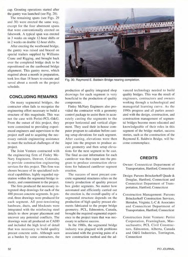
Fig. 30. Raymond E. Baldwin Bridge nearing completion.
production of quality integrated shop drawings for each segment is very beneficial to the production of quality components.
Finley McNary Engineers also provided the contractor with a geometry control package to assist them in accurately casting the segments to the proper horizontal and vertica l alignment. They used their in-house computer program to calculate before casting setup elevations for each segment. After casting, elevations were then input into the program to produce ascast geometry and then setup elevations for the next segment to be cast. The final as-cast information for each canti lever was then input into the program to produce construction elevations for balanced cantilever segment erection.
The success of most precast concrete segmental structures relies on the timely production of quality precast box girder segments. No matter how automated and efficiently carried out the erection is, the overall quality of a segmental structure depends on the production of high quality precast elements fabricated to the proper bridge geometry. PCL, Edmonton , Canada, brought the required segmental experience to the project team that was necessary to achieve success.
In the 1980s, the segmental bridge industry was plagued with problems associated with the growing pains of a new construction method and the ad-
vanced technology needed to build quality bridges. This was the result of engineers , contractors and owners working through a technological and managerial learning curve. As the 1990s progress and all parties associated with the design, construction, and construction management of segmental bridges become more educated and knowledgeable of their roles in this segment of the bridge market, success stories , such as the construction of the Raymond E. Baldwin Bridge, will become commonplace.
CREDITS
Owner: Connecticut Department of Transportation, Hartford, Connecticut
Design: Parsons Brinckerhoff Quade & Douglas, Hartford, Connecticut and Connecticut Department of Transportation, Hartford, Connecticut
Construction Management: Parsons Brinckerhoff Construction Services, Herndon, Virginia; L-C & Associates and Connecticut Department of Transportation, Hartford, Connecticut
Construction Joint Venture: Perini Corporation , Framingham , Massachusetts; PCL Civil Constructors , Edmonton , Alberta, Canada and O&G Industries , Torrington , Connecticut
PCI JOURNAL