Fabric Soft Poly-Limbs for Physical Assistance of Daily ...
7
Fabric Soft Poly-Limbs for Physical Assistance of Daily Living Tasks Pham H. Nguyen, Student Member, IEEE, Imran I. B. Mohd, Curtis Sparks, Francisco L. Arellano, Wenlong Zhang ∗ , Member, IEEE and Panagiotis Polygerinos, Member, IEEE Abstract— This paper presents the design and development of a highly articulated, continuum, wearable, fabric-based Soft Poly-Limb (fSPL). This fabric soft arm acts as an additional limb that provides the wearer with mobile manipulation assis- tance through the use of soft actuators made with high-strength inflatable fabrics. In this work, a set of systematic design rules is presented for the creation of highly compliant soft robotic limbs through an understanding of the fabric based components behavior as a function of input pressure. These design rules are generated by investigating a range of parameters through computational finite-element method (FEM) models focusing on the fSPL’s articulation capabilities and payload capacity in 3D space. The theoretical motion and payload outputs of the fSPL and its components are experimentally validated as well as additional evaluations verify its capability to safely carry loads 10.1x its body weight, by wrapping around the object. Finally, we demonstrate how the fully collapsible fSPL can comfortably be stored in a soft-waist belt and interact with the wearer through spatial mobility and preliminary pick-and-place control experiments. I. INTRODUCTION Individuals with upper-limb impairments typically experi- ence difficulty performing motor tasks, such as activities of daily living (ADLs). These populations could benefit from a soft wearable collaborative robotic device, such as the fabric- based, Soft-Poly Limb (fSPL) presented in this work. Wearable robotics manipulators are devices that can be worn to provide an additional appendage to assist and support the user to perform tasks. These devices do not kinematically have to match the human body’s anatomy, like exoskeletons [1], or prosthetic devices [2]. Recent examples of different wearable collaborative robotic devices include robotic legs [3], [4], arms [5]–[7], fingers [8]–[10], ranging from industrial [5] to medical applications [10]. Wearable manipulators generally face limitations that orig- inate from their rigid designs, like their weight, bulk, and the interaction between rigid elements and the human body [11]. Soft robotics has emerged as one of the solutions to tackle these aforementioned challenges. It has introduced a variety of soft continuum manipulators subdivided based ∗ Address all correspondence to this author. Pham H. Nguyen, Curtis Sparks, Wenlong Zhang and Panagiotis Polygerinos are with the Polytechnic School, Ira A. Fulton Schools of Engineering, Arizona State University, Mesa, AZ 85212, USA. [email protected]; [email protected]; [email protected] Imran I. B. Mohd The School for Engineering of Matter, Transport and Energy, Ira A. Fulton Schools of Engineering, Arizona State University, Tempe, AZ 85281, USA. [email protected] Francisco L. Arellano The School of Biological Health Systems Engi- neering, Ira A. Fulton Schools of Engineering, Arizona State University, Tempe, AZ 85281, USA. [email protected] Fig. 1: (a) Illustrated concept of the fSPL. (b) The prototype fSPL. (c) Left-to-right: the limb is collapsed and stored in a pouch and then deployed to assist with tasks, such as picking up a cup. on actuators that constitute them, including cable-driven [12], [13], pneumatic artificial muscles (PAMs) [14]–[17], elastomeric [18]–[21], origami [22], and inflatable-fabric [23]–[29] based manipulators. The fusion of soft robotics and wearable manipulators has created a new category of robotics which we call, Soft Poly- Limbs (SPLs) [30]. Limited research has started to emerge in this category, Tiziani et al. [10] has introduced a soft poly- finger device, Liang et al. [27] have suggested a two-DOF fabric-based soft poly-arm device that would eventually be integrated as a wearable robot, but have not evaluated the device for this use case yet. Finally, we recently introduced an elastomeric SPL device [30] capable of wrapping around objects to lift approximately 2.35x its own weight. In this paper, we have designed a novel, highly maneu- verable, lightweight SPL capable of assisting users made entirely of fabric (Fig. 1) capable of lifting up to 1.5kg, while counteracting gravity in an outstretched position. We further investigate the mechanical behavior of the fabric- based SPL (fSPL) and its components by using a set of design parameters to optimize the payload capacity of the fSPL by using new computational finite element method (FEM) models that are validated experimentally. We also assess the large degrees of freedom of the fSPL through a workspace experiment and its ability to carry load, up to 10.1x its body weight, by wrapping around an object. Finally, through a series of experiments we showcase the potential of the fSPL, capable of compressing to 1/2 its entire length, to work safely around the wearer and assist with ADLs.
Transcript of Fabric Soft Poly-Limbs for Physical Assistance of Daily ...
Fabric Soft Poly-Limbs for Physical Assistance of Daily Living Tasks
Pham H. Nguyen, Student Member, IEEE, Imran I. B. Mohd, Curtis Sparks, Francisco L. Arellano,
Wenlong Zhang∗, Member, IEEE and Panagiotis Polygerinos, Member, IEEE
Abstract— This paper presents the design and developmentof a highly articulated, continuum, wearable, fabric-based SoftPoly-Limb (fSPL). This fabric soft arm acts as an additionallimb that provides the wearer with mobile manipulation assis-tance through the use of soft actuators made with high-strengthinflatable fabrics. In this work, a set of systematic design rulesis presented for the creation of highly compliant soft roboticlimbs through an understanding of the fabric based componentsbehavior as a function of input pressure. These design rulesare generated by investigating a range of parameters throughcomputational finite-element method (FEM) models focusingon the fSPL’s articulation capabilities and payload capacity in3D space. The theoretical motion and payload outputs of thefSPL and its components are experimentally validated as wellas additional evaluations verify its capability to safely carryloads 10.1x its body weight, by wrapping around the object.Finally, we demonstrate how the fully collapsible fSPL cancomfortably be stored in a soft-waist belt and interact with thewearer through spatial mobility and preliminary pick-and-placecontrol experiments.
I. INTRODUCTION
Individuals with upper-limb impairments typically experi-
ence difficulty performing motor tasks, such as activities of
daily living (ADLs). These populations could benefit from a
soft wearable collaborative robotic device, such as the fabric-
based, Soft-Poly Limb (fSPL) presented in this work.
Wearable robotics manipulators are devices that can be
worn to provide an additional appendage to assist and
support the user to perform tasks. These devices do not
kinematically have to match the human body’s anatomy, like
exoskeletons [1], or prosthetic devices [2]. Recent examples
of different wearable collaborative robotic devices include
robotic legs [3], [4], arms [5]–[7], fingers [8]–[10], ranging
from industrial [5] to medical applications [10].
Wearable manipulators generally face limitations that orig-
inate from their rigid designs, like their weight, bulk, and
the interaction between rigid elements and the human body
[11]. Soft robotics has emerged as one of the solutions to
tackle these aforementioned challenges. It has introduced
a variety of soft continuum manipulators subdivided based
∗ Address all correspondence to this author.Pham H. Nguyen, Curtis Sparks, Wenlong Zhang and Panagiotis
Polygerinos are with the Polytechnic School, Ira A. FultonSchools of Engineering, Arizona State University, Mesa, AZ85212, USA. [email protected]; [email protected];[email protected]
Imran I. B. Mohd The School for Engineering of Matter, Transport andEnergy, Ira A. Fulton Schools of Engineering, Arizona State University,Tempe, AZ 85281, USA. [email protected]
Francisco L. Arellano The School of Biological Health Systems Engi-neering, Ira A. Fulton Schools of Engineering, Arizona State University,Tempe, AZ 85281, USA. [email protected]
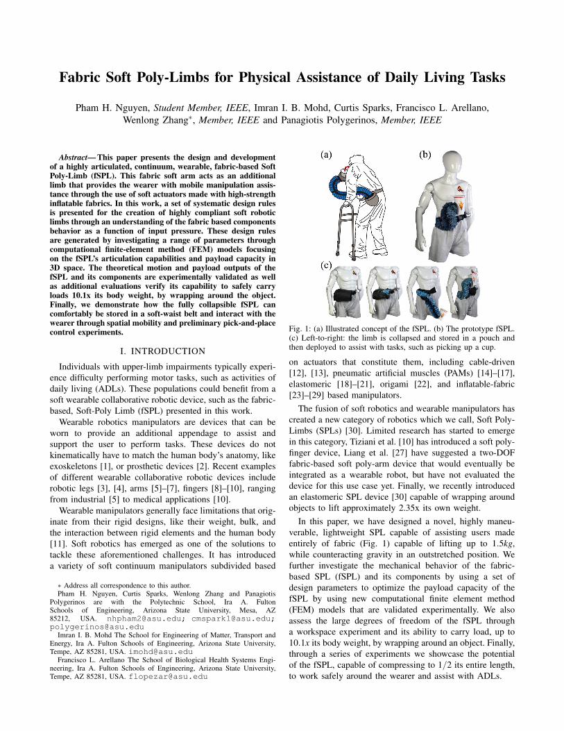
Fig. 1: (a) Illustrated concept of the fSPL. (b) The prototype fSPL.(c) Left-to-right: the limb is collapsed and stored in a pouch andthen deployed to assist with tasks, such as picking up a cup.
on actuators that constitute them, including cable-driven
[12], [13], pneumatic artificial muscles (PAMs) [14]–[17],
elastomeric [18]–[21], origami [22], and inflatable-fabric
[23]–[29] based manipulators.
The fusion of soft robotics and wearable manipulators has
created a new category of robotics which we call, Soft Poly-
Limbs (SPLs) [30]. Limited research has started to emerge
in this category, Tiziani et al. [10] has introduced a soft poly-
finger device, Liang et al. [27] have suggested a two-DOF
fabric-based soft poly-arm device that would eventually be
integrated as a wearable robot, but have not evaluated the
device for this use case yet. Finally, we recently introduced
an elastomeric SPL device [30] capable of wrapping around
objects to lift approximately 2.35x its own weight.
In this paper, we have designed a novel, highly maneu-
verable, lightweight SPL capable of assisting users made
entirely of fabric (Fig. 1) capable of lifting up to 1.5kg,
while counteracting gravity in an outstretched position. We
further investigate the mechanical behavior of the fabric-
based SPL (fSPL) and its components by using a set of
design parameters to optimize the payload capacity of the
fSPL by using new computational finite element method
(FEM) models that are validated experimentally. We also
assess the large degrees of freedom of the fSPL through
a workspace experiment and its ability to carry load, up to
10.1x its body weight, by wrapping around an object. Finally,
through a series of experiments we showcase the potential
of the fSPL, capable of compressing to 1/2 its entire length,
to work safely around the wearer and assist with ADLs.

TABLE I: Requirements for a fabric-based Soft-Poly Limb (fSPL)
Characteristics Requirements
Weight of Device Approx. 1.0kg
Profile of fSPL Less than 100mm diameterPayload (fully extended) Approx. 1kg
Payload (whole-body grasp) 2x the weight of deviceMax. Reach Length Length of male arm (0.59m)Min. Retraction Length Half of fully stretched SPLSafety Easy to don-and-doff
Does not interfere withbiological limb’s movement
Degrees-of-Freedom (DOF) Infinite DOF (continuum)Degrees of Curvature of Each Segment 180◦
II. DESIGN AND FABRICATION OF FSPL
A. Functional Requirements
In order to provide long-term options to users who have
lost/reduced function in their hands and arms we have laid
out a soft robotic architecture with functional requirements,
as summarized in Table I. We intend to provide the wearer
with a full-length SPL that interacts safely with the user
and the environment. Because of the inflatable fabric ma-
terials we intend to utilize for its structure and motion, we
anticipate a lightweight (approximately 1kg) and slim body
that can be collapsed, several times its original length, and
stowed away in a pouch attached to a waist belt without
adding bulkiness or impeding the user’s motion. In general,
the hyperredundant SPL should be a highly maneuverable
manipulator exceeding the biological arm capabilities by
offering infinite number of kinematic DOFs. This can be
achieved by utilizing soft continuum designs, which could
also offer configurable and compliant motions. Considering
manipulation of most daily living objects, the system should
also be able to carry up to approximately 1kg of payload at
its end-effector while being fully-extended and positioned
Fig. 2: a) The actuator array when inflated. b) The CNC Process tofabricate fabric actuators. c) Each singular fabric actuator. d) Theentire fSPL composed of 3 segments of f3BAs.
TABLE II: Material Properties of TPU Coated Nylon Fabrics
Material Density Seal Strength Burst(kg/m3) (N) Strength
(MPa)
Rockywoods 200D 840.00 168.35 0.53±0.04Outdoor Oxford 200D 757.58 183.68 0.48±0.03Ripstop 200D 758.62 192.19 0.40±0.017Seatle Diamond 200D 892.86 164.75 0.36±0.026DIY Packraft 400D 982.46 155.32 0.20±0.026DIY Packraft 1000D 1000.00 236.17 0.11±0.02Taffeta 70D 700.00 150.59 0.048±0.008
parallel to the ground. Finally, because of its soft and
continuum nature, the arm would be able to achieve whole-
body grasping and manipulate even higher loads by wrapping
around objects and distributing the loads.
B. Material Selection
The applicability and functionality of fabric bending actu-
ator arrays have been highlighted in our previous work [31],
where thin thermoplastic polyurethane (TPU) actuators en-
cased in nylon fabric casings are able to withstand pressures
higher than 0.3MPa. Instead, in this work a variety of heat-
sealable TPU-coated nylon fabric materials are explored to
develop soft actuators that are robust to external environmen-
tal interactions, allow for a single-step fabrication process
to save manufacturing time, and are capable of withstanding
even higher pressures (up to 0.53MPa), thus achieving higher
bending and torque outputs.
A set of TPU-coated nylon fabrics with dernier values
ranging from 70D to a 1000D are characterized against seal
strength peel and burst tests, as seen in Table II. It is noted
that the dernier number indicates the fiber thickness of the
filament used for their fabrication.
We perform a seal strength peel test, with the ASTM
F88/F88M-15 protocol. We then further test them for the
maximum pressure they could withstand until failure (burst
test), using the ASTM F2054 protocol. Based on the results,
the Rockywoods 200D heat-sealable fabric (6607, Rocky-
woods Fabric, Loveland, CO) is chosen for its highest burst
strength of 0.53MPa.
C. Design, Fabrication and Integration
To meet the functional requirements, the length of the
fSPL is designed to match the length of an average sized
adult male arm, approximately 0.59m [32], from the tip
of the shoulder to the center of the wrist. The fSPL is
subdivided into three active segments called the fabric 3
bending actuators (f3BAs), as seen in Fig. 2d. Each segment
further consists of three bending actuators arrays (shown
in Fig. 2a arranged and sewn into an equilateral triangle
prism to create the f3BA segment. Each bending actuator
array is comprised of multiple high-strength, heat-sealed,
TPU-coated nylon (200D) fabric actuators (shown in Fig.
2c, previously selected in Section II-B.
To develop the fabric actuators, the selected material is
cut into a rectangular shape using a laser cutter (Glowforge
Pro, Glowforge, Seattle, WA) and the pneumatic fittings
are attached (5463K361, McMaster-Carr, Elmhurst, IL). A

sealant is also added around the fittings to prevent air leakage
(Seam Grip, Gear Aid, Bellingham, WA). The material is
arranged on a customized CNC router (Shapeoko 3, Carbide
Motion, Torrance, CA) with a soldering iron tip set at
230◦C and traced to seal the fabric actuators, as seen in
Fig. 2b. This apparatus enables rapid heat-sealing of fabric
soft actuator patterns accurately and repeatedly, up to 25
individual actuators at a time for this limb design.
Fabric pockets to slot the individual actuators are evenly
sewn into a parallel array configuration onto a strain-limited
fabric layer. The individual actuators as depicted in Fig. 2c,
are inserted into the pockets, creating actuator arrays. When
the actuators inflate, their interaction causes the actuator
array to bend or even curl completely, as shown in Fig. 2a.
Modular 3D-printed connectors are sewn into the distal
and proximal ends of each f3BA and used to connect all
the segments, creating the complete fSPL (Fig. 2d). The
modularity of the connector pieces allow for a variety of
end-effectors to be mounted at the distal end of the fSPL,
such as a suction cup (5427A636, McMaster-Carr, Elmhurst,
IL). A zippered fabric pouch is designed to store the fSPL
by collapsing its body to less than half its full length. To
interface the fSPL with the human body, the fabric pouch is
sewn onto a modified technical belt (S&F Deluxe Technical
Belt, Lowepro, Petaluma, CA) as shown in Fig. 1c. This
0.5kg waist belt, designed to be don-doff friendly, ensures
that loads carried by the fSPL can be evenly distributed along
the waist of the wearer without creating pressure points.
III. FEM-BASED OPTIMIZATION OF FSPL
An FEM modeling approach is used to predict the bending
performance and tip payload force of the fSPL and its
components throughout this work. It is also used to identify
the geometrical parameters, as seen in Fig. 3, that maximize
the tip force of the actuator array design. In this work, we
introduce the use of ABAQUS/Explicit (Simulia, Dassault
Fig. 3: a) Isometric view of actuator array. b) Bottom view of f3BA.c) Side view of bending actuator array.
Systemes) and shell elements to model inflatable thin plastic
films. Because of the large deformations and short dynamic
response times observed amongst the fabric actuators, con-
vergence of computational solutions can be only obtained
through an explicit (dynamic) simulation environment.
The materials properties used in our simulations include
the linear elastic modulus, determined with ASTM D882,
of the TPU-coated nylon selected in Section II-B (Young’s
modulus of E = 498MPa and Poissons ratio of v = 0.35),
the properties for the inextensible fabric layer used to hold
the actuators evenly-spaced in an array (E = 305MPa, v =
0.35), and the properties used for the PLA connector caps
(E = 3600, v = 0.3). All the components of the actuators are
modeled using shell explicit quadratic tetrahedral elements
(C3D10M).
Although the explicit solution is a true dynamic procedure,
it has the valuable capability of solving quasi-static contact
problems as well. In our case, it would be the actuator arrays
inflating to contact the force plate to measure the tip payload
force. Because it is impractical to simulate the event in a
natural time scale as it would be computationally demanding,
the explicit solution would need to be accelerated, while still
maintaining its dynamic equilibrium. The first requirement is
to ensure loading is as smooth as possible, so not to introduce
noise. This is achieved by controlling the loading rate of
the analysis at 1% of the speed of the stress wave of the
material. To verify if quasi-static conditions are achieved in
the simulation, the requirement is to inspect that the total
kinetic energy of the deforming material does not exceed 5%
of its total internal energy (IE) throughout the simulation.
A. Geometrical Parameters of Fabric Actuators
To study the payload and bending capabilities of the fSPL
prior to fabrication, a set of geometrical parameters, as
highlighted in Fig. 3, are studied. The three main geometrical
parameters studied and optimized are the active (i.e. without
the seam length) width and height of the actuators (wa and
ha), and the number of actuators (n) based on their major
contribution to the bending and payload capacity of the fSPL.
The active height (ha) contributes to the bending capabil-
ity, while the active width (wa) contributes to the stability
of the actuator array of length, al . If wa is less than ha then
the contact surface between consecutive actuators will be
smaller and therefore the actuators will lose friction resulting
in torsional motions and decreased force distribution.
Therefore, wa is set to be greater than ha by a ratio r that is
larger or equal to at least 1.0. The active width and height are
also constrained by the diameter of the physical tube fitting fl
that will be used, which is 6.2mm, and the heat seam width
sl created by the heat sealer, which is 5mm. The spacing
between the actuators (sp) is limited to over 7.5mm because
of sewing manufacturing limitations. Both the active width
and height of the actuator are also constrained by Rc, which
defines the cross-sectional radius of the fSPL, constrained
to 50mm. The angle of the inflated actuator array θn, is
designed to achieve at least 180◦ when fully inflated. The

Fig. 4: FEM analysis of number of actuators and ratio (r = wa/ha)with regards to the force (N) generated by actuator array.
aforementioned physical constraints are summarized below:
Rc = 50mm, sl ≥ 5mm, θn = 180◦,
fl = 6.23mm, al = 160mm, sp ≥ 7.5mm.
Using the number of actuators (n) and the spacing (sp),
the active height (ha) can be calculated as follows:
wa = r ·ha, (1)
sp =(al −2 · (al/n))
n, (2)
ha =sp ·π
2 · (1− sin(θn/(2 ·n)). (3)
From the circumradius (Rc) and inradius (Ri) of Fig. 3b,
we can calculate the active width (wa) as:
wa ≤ Rc/(
√3
6+
1
r)−2 · sl − fl . (4)
B. FEM Optimization of Geometrical Parameters
To find the geometrical parameters required to maximize
the tip force of the bending actuator array, we use FEM
simulations with varying parameters, the ratio (r) and the
number of actuators (n). The number of actuators (n) is
varied based on the minimum and maximum sp. The maxi-
mum n is determined from (2) by the minimum sp ≥ 7.5mm,
which demonstrates that n = 19 is the optimum number.
The minimum n is determined by the number of actuators
Fig. 5: Payload capability of a single actuator array comparedbetween FEM and experimentally validated, repeated 3 times
TABLE III: UTM and Free-space Bending Payload
Component UTM Payload Free-space Loading(N) Payload (N or kg)
Exp. FEM
Actuator Array 174.73±6.37 177.2 –f3BA 53.73±1.04 56.9 58.8 or 6.0fSPL 14.91±0.93 20.0 14.7 or 1.5
required to generate significant tip force from the actuator
array as n = 8. Thus from our study, more actuators in the
actuator array, contributes to a larger tip force. By varying
the ratio (r) between wa and ha, from 1.0 to 3.5, we notice
that the tip force increases with the increasing ratio until
a ratio of 2.0 is reached. After which the force decreases
because the radius of the inflated actuator becomes smaller
than the spacing (sp) between the actuators. Therefore, the
configuration that produces the highest tip force (n= 19) and
is less likely to to present actuator slippage is selected, with
ratio (r = 2.0), as seen in Fig. 4.
IV. TESTING AND EVALUATION OF FSPL
For the fSPL to be effective during everyday use, it is
important to carry the desired payload and maneuver it
effectively within the 3D workspace of the wearer. Therefore,
to assess the capability of the fSPL, we explore experimental
validations of the FEM models, various payload experiments,
the workspace of the fSPL, and finally users’ ability to
perform pick-and-place experiments.
A. Payload Capacity
We have designed two experiments to investigate payload
capacity of the fSPL and its components; the actuator array
and f3BA. The first experiment (UTM experiment) requires
to have the soft components inflate upwards against a force
sensor while mounted on a universal testing machine (UTM
Instron 5944, Instron Corp., High Wycombe, United King-
dom). The force output (payload) is measured at small pres-
sure increments of 0.069MPa until 0.34MPa is reached. The
second experiment (free-space loading experiment) requires
the components to lift a set of known weights mounted at the
end-effector position from a deflated state until the parallel
to the ground configuration is achieved, as verified using
Fig. 6: Payload capability of a f3BA unit compared between FEMand experimentally validation, repeated 3 times.

Fig. 7: Bending capability of a f3BA unit compared between FEMand experimentally validated
recorded video reference. The experiment is repeated with
an increased load until this configuration can no longer be
achieved. The results for both experiments are summarized
in Table III. Each payload experiment is repeated 3 times for
the SPL and its components.
1) Payload capacity of the actuator array: The FEM
and experimental data comparison for the UTM experiment
are seen in Fig. 5. Both present similar payload output
trends with a root mean square error (RSME) of 9.087N.
As seen in Table III, the single actuator array is capable of
producing 177.2N in the FEM simulation and 174.7±6.367N
experimentally, demonstrating a discrepancy error of 1.4%.
2) Payload capacity of the f3BA: The load capacity when
the bottom two adjacent actuator arrays of the f3BA are
inflated, is shown in Fig. 6, with an RMSE calculated at
4.05N between FEM and experiment. The maximum payload
for FEM simulation and experimental validation is 56.9N and
53.7±1.041N, respectively. Investigating the payload capac-
ity for the f3BA in the free-space loading experiment is found
capable of lifting a maximum load of 5.5kg, approximately
15.1x its own weight of 0.37kg.
3) Payload capacity of the fSPL: For the UTM experi-
ment, the payload from the fSPL FEM simulation and ex-
perimental validation is found to be 20N and 14.91±0.926N,
respectively. In this experiment, the lower adjacent cham-
bers of the two proximal segments are pressurized up to
0.345MPa while the lower adjacent chambers of the distal
segment are pressurized up to 0.207MPa. Under the same
pressurization scheme in the free-space loading experiment,
the maximum payload capacity for the 1.1kg fSPL is found
to be 1.5kg, surpassing the desired payload goal of 1kg set
in Section II-A.
B. Motion Trajectory Tracking
1) f3BA Motion Trajectory: An experiment to compare
the motion trajectory of a f3BA segment of the FEM model
with this of the prototype is conducted. A set of passive
reflective markers are attached to the distal end of the
segment while motion capture cameras (Optitrack Prime
13W, NaturalPoint Inc., Corvallis, OR) are used to track
their motion when one side of the segment is inflated to
0.345MPa quasi-statically, as seen in Fig. 7. The end-effector
position of the f3BA, in the FEM simulation and physical
experiment, differ by a Euclidean distance error of 6.8mm.
Fig. 8: Comparison of the FEM simulation vs experimentallyvalidated pose for fSPL
The displacement error from the initial, unpressurized f3BA
segment position is 3.9%.
2) fSPL Motion Trajectory: To study the FEM model’s
ability to predict the non-linear motion behavior produced by
the fSPL, a highly complex pose of the fSPL is generated
arbitrarily and recorded using the motion capture system,
as shown in Fig. 8. Markers are added at the proximal and
distal end of every segment to create virtual rigid bodies.
The pose is achieved by inflating the alternating bottom
actuator arrays of each segment to 0.207MPa respectively
in FEM. The experimental pose is achieved by inflating
the same actuator sequence by 0.207MPa, 0.241MPa, and
0.172MPa subsequently. There is a slight variation in the
inflation of the second and third segment by ±0.0345MPa
to compensate for the differences in FEM and reality, like
manufacturing inconsistencies.The experimental Euclidean
displacement error is calculated at 3.96cm with FEM model
estimated pose and had a 7.55% displacement error.
Fig. 9: a) Pick-and-place test using suction end-effector with fSPL.Wrap around grasping method for a b) ball c) box d) bag.

TABLE IV: Pick-and-Place Time Duration
Users Attempt Attempt Attempt Attempt Attempt1 2 3 4 5
1 53.28s 37.28s 27.17s 25.16s 24.70s
2 45.34s 33.88s 22.33s 21.43s 20.79s
3 27.68s 21.89s 19.60s 17.00s 13.12s
C. Pick-and-Place User Experiments
To test the motion performance of the fSPL when used
in real-life situations, along with user controllability, a pick-
and-place experiment is performed with a number of human
participants (n=3). For this experiment, a vacuum suction cup
is used at the fSPL’s end-effector. The vacuum suction cup
has a theoretical payload of 0.86kg and is connected to a
vacuum pump with depressurization rate of 1.42x10⁻³m3/s.
The experiment is set up for the user to operate the fSPL
using a joystick controller previously introduced [30], to pick
a jar with peanut butter (0.3kg) on one end of a table and
move it across and inside a target box (0.33x0.16x0.12m)
that is placed 0.45m away, as seen in Fig. 9. Three first-
time users are timed while performing the task five times
each. The timed results are shown in table IV demonstrating
the gradual adoption and improvement in controlling a soft,
external limb. A variety of other daily livings objects are
also successfully picked and placed, including a hair spray
canister (0.43kg) and a water bottle (0.88kg).
D. Whole-Body Continuum Grasping
Similar to an elephant using its trunk, the fSPL is also
capable of manipulating objects, larger than the size of the
end-effector, by wrapping itself around them. In order to
identify the effective whole-body grasping tactic, a trial and
error process was used. The most efficient grasping method
to carry heavier and larger objects is shown in Fig. 9b,
where the majority of the load is supported by the proximal
segment, while creating a tight wrap around the object
against the body of the user that is standing upright. To
demonstrate this feature, the fSPL is attached to a belt worn
by a user and inflated to wrap around various objects. The
objects tested include a soccer ball (0.45kg), a box (1.75kg),
and a backpack (initially 1.61kg), as seen in Fig. 9. The
maximum payload capacity using this method is tested by
gradually adding weights into the backpack resulting in a
load of 11.13kg (10.1x its own body weight) before the fSPL
loses support.
E. Workspace
To evaluate the effective workspace, the fSPL is mounted
parallel to the ground. Two sets of reflective markers are
placed at the distal and proximal ends of the fSPL to create
virtual rigid bodies. The position of the markers is recorded
using a motion capture system. The individual actuator
arrays of the limb are inflated in various configurations
using a maximum pressure of 0.34MPa to cover their entire
workspace. The workspace of the fSPL is generated from the
collected end-effector positions shown in Fig 10. The fSPL is
shown capable of reaching any point inside this workspace,
Fig. 10: The workspace of the fSPL in the coronal plane.
where the shaded colors show the change in height in the
Z-axis. Resulting in an effective volume of 0.123m3, with a
maximum vertical range of 0.63m and maximum horizontal
range of 0.695m. This workspace provides enough vertical
and horizontal range to support a user in ADL tasks in the
coronal plane, based on how it is mounted. This orientation
can be adjusted based on the task and user preference to
optimize the effective workspace.
V. CONCLUSION AND FUTURE WORK
In this paper, the design, development, and evaluation
of a novel, user-mounted, fabric Soft Poly-Limb (fSPL)
was introduced utilizing high-strength inflatable fabrics. The
highly-articulated, soft fSPL was designed towards support-
ing and assisting individuals to perform ADL. The fSPL’s
geometrical parameters were optimized and preliminary ex-
perimentally validated using quasi-static computational FEM
models, providing design guidelines for the community to
design fSPLs based on the desired payload capacity and
articulation performance.
Each fSPL segment was capable of effectively lifting 15.1x
its own weight at 5.5kg and the entire fSPL demonstrated
the capacity to carry up to 1.5kg of load (1.5x its total
weight) while able to maneuver in space. By employing
the whole body grasping methodology, the fSPL was shown
able to wrap around and carry loads of up to 11.13kg, over
10.1 times its own body weight. Furthermore, the fSPL
demonstrated its complex motion abilities by operating when
worn by users while offering a large workspace and safely
interacting with the environment.
Future work will introduce the exploration of multi-
mounting positions and multiple interacting fSPLs on users
to expand the workspace and capabilities of controlling
multi-external limbs. Further exploration of various user-
intent detection methods will also be explored to control the
fSPL, hands-free. Implementation of on-board actuation and
power supply systems that are capable of controlling such
a complicated system are being explored. Future efforts are
being made to control the SPL using distributed sensing and
control methods [33] with the exploration of soft-distributed
and embedded sensing technologies as well.
ACKNOWLEDGMENTS
This work was supported in part by the National Science
Foundation under Grant CMMI-1800940.

REFERENCES
[1] R A R C Gopura, Kazuo Kiguchi, and D S V Bandara. A briefreview on upper extremity robotic exoskeleton systems. In 2011
6th International Conference on Industrial and Information Systems,volume 8502, pages 346–351, aug 2011.
[2] Robert Bogue and Robert Bogue. Exoskeletons and robotic pros-thetics: a review of recent developments. Industrial Robot: the
international journal of robotics research and application, 36(5):421–427, 2009.
[3] Daniel A Kurek and H Harry Asada. The MantisBot: Design andImpedance Control of Supernumerary Robotic Limbs for Near-GroundWork. In 2017 IEEE International Conference on Robotics and
Automation (ICRA), pages 5942–5947, may 2017.[4] Federico Parietti, Kameron C. Chan, Banks Hunter, and H. Harry
Asada. Design and control of Supernumerary Robotic Limbs for bal-ance augmentation. In Proceedings - IEEE International Conference
on Robotics and Automation, volume 2015-June, pages 5010–5017,may 2015.
[5] Federico Parietti and H. Harry Asada. Supernumerary Robotic Limbsfor aircraft fuselage assembly: Body stabilization and guidance bybracing. In 2014 IEEE International Conference on Robotics and
Automation (ICRA), pages 1176–1183, may 2014.[6] M H D Yamen Saraiji, Tomoya Sasaki, Reo Matsumura, Kouta
Minamizawa, and Masahiko Inami. Fusion: Full Body Surrogacy forCollaborative Communication. In ACM SIGGRAPH 2018 Emerging
Technologies, SIGGRAPH ’18, pages 7:1—-7:2, New York, NY, USA,2018. ACM.
[7] Vighnesh Vatsal and Guy Hoffman. Wearing Your Arm on Your Sleeve: Studying Usage Contexts for a Wearable Robotic Forearm. In 2017
26th IEEE International Symposium on Robot and Human Interactive
Communication (RO-MAN), pages 974–980, aug 2017.[8] Irfan Hussain, Gionata Salvietti, Giovanni Spagnoletti, Monica
Malvezzi, David Cioncoloni, Simone Rossi, and Domenico Prat-tichizzo. A soft supernumerary robotic finger and mobile arm supportfor grasping compensation and hemiparetic upper limb rehabilitation.Robotics and Autonomous Systems, 93:1–12, 2017.
[9] Faye Y. Wu and H. Harry Asada. ’Hold-and-manipulate’ with a singlehand being assisted by wearable extra fingers. In Proceedings - IEEE
International Conference on Robotics and Automation, volume 2015-June, pages 6205–6212, 2015.
[10] Lucas Tiziani, Alexander Hart, Thomas Cahoon, Faye Wu, H HarryAsada, and Frank L Hammond. Empirical characterization of modularvariable stiffness inflatable structures for supernumerary grasp-assistdevices. The International Journal of Robotics Research, 36(13-14):1391–1413, 2017.
[11] Antonio J. Del-Ama, Aikaterini D. Koutsou, Juan C. Moreno, AnaDe-los Reyes, Ngel Gil-Agudo, and Jos L. Pons. Review of hybridexoskeletons to restore gait following spinal cord injury. The Journal
of Rehabilitation Research and Development, 49(4):497, 2012.[12] William McMahan, Bryan A. Jones, and Ian D. Walker. Design and
implementation of a multi-section continuum robot: Air-octor. In 2005
IEEE/RSJ International Conference on Intelligent Robots and Systems,
IROS, number January, pages 3345–3352, aug 2005.[13] M. Calisti, M. Giorelli, G. Levy, B. Mazzolai, B. Hochner, C. Laschi,
and P. Dario. An octopus-bioinspired solution to movement and ma-nipulation for soft robots. Bioinspiration & Biomimetics, 6(3):36002,2011.
[14] Ian D. Walker, Darren M. Dawson, Tamar Flash, Frank W. Grasso,Roger T. Hanlon, Binyamin Hochner, William M. Kier, Christopher C.Pagano, Christopher D. Rahn, and Qiming M. Zhang. Continuumrobot arms inspired by cephalopods. SPIE Conference on Unmanned
Ground Vehicle Technology, 5804:303–314, 2005.[15] Isuru S. Godage, Gustavo A. Medrano-Cerda, David T. Branson,
Emanuele Guglielmino, and Darwin G. Caldwell. Dynamics for vari-able length multisection continuum arms. The International Journal
of Robotics Research, 35(6):695–722, 2016.[16] Yasmin Ansari, Mariangela Manti, Egidio Falotico, Yoan Mollard,
Matteo Cianchetti, and Cecilia Laschi. Towards the developmentof a soft manipulator as an assistive robot for personal care ofelderly people. International Journal of Advanced Robotic Systems,14(2):1729881416687132, 2017.
[17] Maria Elena Giannaccini, Chaoqun Xiang, Adham Atyabi, TheoTheodoridis, Samia Nefti-Meziani, Steve Davis, Giannaccini MariaElena, Xiang Chaoqun, Atyabi Adham, Theodoridis Theo, Nefti-Meziani Samia, and Davis Steve. Novel Design of a Soft Lightweight
Pneumatic Continuum Robot Arm with Decoupled Variable Stiffnessand Positioning. Soft Robotics, 00(00):soro.2016.0066, 2017.
[18] Matteo Cianchetti, Tommaso Ranzani, Giada Gerboni, Iris De Falco,Cecilia Laschi, Senior Member, and Arianna Menciassi. STIFF-FLOP surgical manipulator: Mechanical design and experimentalcharacterization of the single module. In 2013 IEEE/RSJ International
Conference on Intelligent Robots and Systems, pages 3576–3581, nov2013.
[19] Andrew D. Marchese and Daniela Rus. Design, kinematics, and con-trol of a soft spatial fluidic elastomer manipulator. The International
Journal of Robotics Research, 35(7):0278364915587925–, 2015.[20] Matthew A Robertson and Jamie Paik. New soft robots really
suck: Vacuum-powered systems empower diverse capabilities. Science
Robotics, 2(9):1–12, 2017.[21] Zheyuan Gong, Jiahui Cheng, Xingyu Chen, Wenguang Sun, Xi Fang,
and Kainan Hu. A Bio-inspired Soft Robotic Arm : Kinematic Mod-eling and Hydrodynamic Experiments. Journal of Bionic Engineering,15:204–219, 2018.
[22] Junius Santoso, Erik H Skorina, Ming Luo, Ruibo Yan, and Cagdas DOnal. Design and analysis of an origami continuum manipulationmodule with torsional strength. In IEEE International Conference on
Intelligent Robots and Systems, volume 2017-Septe, pages 2098–2104,2017.
[23] Siddharth Sanan. Soft Inflatable Robots for Safe Physical Human
Interaction. PhD thesis, Carnegie Mellon University, Pittsburgh, PA,aug 2013.
[24] Elliot W Hawkes, Laura H Blumenschein, Joseph D Greer, andAllison M Okamura. A soft robot that navigates its environmentthrough growth. Science Robotics, 2(8):1–8, 2017.
[25] Ohta Preston, Valle Luis, King Jonathan, Low Kevin, Yi Jaehyun,Atkeson Christopher G., Park Yong-Lae, Preston Ohta, Luis Valle,Jonathan King, Kevin Low, Jaehyun Yi, Christopher G. Atkeson, andYong-Lae Park. Design of a Lightweight Soft Robotic Arm UsingPneumatic Artificial Muscles and Inflatable Sleeves. Soft Robotics,0(0):null, 2017.
[26] Charles M. Best, Morgan T Gillespie, Phillip Hyatt, Levi Rupert,Vallan Sherrod, and Marc D Killpack. A New Soft Robot ControlMethod: Using Model Predictive Control for a Pneumatically ActuatedHumanoid. IEEE Robotics & Automation Magazine, 23(3):75–84,2016.
[27] Xinquan Liang, Haris Cheong, Yi Sun, Jin Guo, Chee Kong Chui, andC Yeow. Design , Characterization and Implementation of a Two -DOF Fabric - based Soft Robotic Arm. IEEE Robotics and Automation
Letters, 3766(c):1–8, jul 2018.[28] Masashi Takeichi, Koichi Suzumori, Gen Endo, and Hiroyuki Nabae.
Development of Giacometti Arm With Balloon Body. IEEE Robotics
and Automation Letters, 2(2):2710–2716, 2017.[29] Hye Jong Kim, Akihiro Kawamura, Yasutaka Nishioka, and Sadao
Kawamura. Mechanical design and control of inflatable robotic armsfor high positioning accuracy. Advanced Robotics, 32(2):89–104,2018.
[30] Pham Huy Nguyen, Curtis Sparks, Sai Gautham Nuthi, Nicholas MVale, and Panagiotis Polygerinos. Soft Poly-Limbs: Toward a NewParadigm of Mobile Manipulation for Daily Living Tasks. Soft
Robotics, 00(00):soro.2018.0065, 2018.[31] Carly M. Thalman, Quoc P. Lam, Pham H. Nguyen, Saivimal Sridar,
and Panagiotis Polygerinos. A Novel Soft Elbow Exosuit to Supple-ment Bicep Lifting Capacity. In 2018 IEEE/RSJ International Con-
ference on Intelligent Robots and Systems, IROS, 2018. [Accepted].[32] Stanley Plagenhoef, F. Gaynor Evans, and Thomas Abdelnour.
Anatomical Data for Analyzing Human Motion. Research Quarterly
for Exercise and Sport, 54(2):169–178, 1983.[33] W. Zhang and P. Polygerinos. Distributed planning of multi-segment
soft robotic arms. In 2018 Annual American Control Conference
(ACC), pages 2096–2101, June 2018.