FAA-H-8083-3A, Airplane Flying Handbook -- 6 of 7 fileshatcheraviation.com/uploads/AFH Chap 14...
12
14-1 GENERAL The turbopropeller-powered airplane flies and handles just like any other airplane of comparable size and weight. The aerodynamics are the same. The major differences between flying a turboprop and other non-turbine-powered airplanes are found in the power- plant and systems. The powerplant is different and requires operating procedures that are unique to gas turbine engines. But so, too, are other systems such as the electrical system, hydraulics, environmental, flight control, rain and ice protection, and avionics. The turbopropeller-powered airplane also has the advantage of being equipped with a constant speed, full feathering and reversing propeller—something normally not found on piston-powered airplanes. THE GAS TURBINE ENGINE Both piston (reciprocating) engines and gas turbine engines are internal combustion engines. They have a similar cycle of operation that consists of induction, compression, combustion, expansion, and exhaust. In a piston engine, each of these events is a separate distinct occurrence in each cylinder. Also, in a piston engine an ignition event must occur during each cycle, in each cylinder. Unlike reciprocating engines, in gas turbine engines these phases of power occur simultaneously and continuously instead of one cycle at a time. Additionally, ignition occurs during the starting cycle and is continuous thereafter. The basic gas turbine engine contains four sections: intake, compression, combustion, and exhaust. [Figure 14-1] To start the engine, the compressor section is rotated by an electrical starter on small engines or an air driven starter on large engines. As compressor r.p.m. accelerates, air is brought in through the inlet duct, compressed to a high pressure, and delivered to the combustion section (combustion chambers). Fuel is then injected by a fuel controller through spray nozzles and ignited by igniter plugs. (Not all of the compressed air is used to support combustion. Some of the compressed air bypasses the burner section and circu- lates within the engine to provide internal cooling.) The fuel/air mixture in the combustion chamber is then burned in a continuous combustion process and produces a very high temperature, typically around 4,000°F, which heats INTAKE COMPRESSION COMBUSTION EXHAUST Air Inlet Compression Combustion Chambers Turbine Exhaust Cold Section Hot Section Figure 14-1. Basic components of a gas turbine engine. Ch 14.qxd 5/7/04 10:08 AM Page 14-1
Transcript of FAA-H-8083-3A, Airplane Flying Handbook -- 6 of 7 fileshatcheraviation.com/uploads/AFH Chap 14...
14-1
GENERALThe turbopropeller-powered airplane flies and handlesjust like any other airplane of comparable size andweight. The aerodynamics are the same. The majordifferences between flying a turboprop and othernon-turbine-powered airplanes are found in the power-plant and systems. The powerplant is different andrequires operating procedures that are unique to gasturbine engines. But so, too, are other systems such asthe electrical system, hydraulics, environmental, flightcontrol, rain and ice protection, and avionics. Theturbopropeller-powered airplane also has the advantageof being equipped with a constant speed, full featheringand reversing propeller—something normally notfound on piston-powered airplanes.
THE GAS TURBINE ENGINEBoth piston (reciprocating) engines and gas turbineengines are internal combustion engines. They have asimilar cycle of operation that consists of induction,compression, combustion, expansion, and exhaust. In apiston engine, each of these events is a separate distinctoccurrence in each cylinder. Also, in a piston engine anignition event must occur during each cycle, in each
cylinder. Unlike reciprocating engines, in gas turbineengines these phases of power occur simultaneouslyand continuously instead of one cycle at a time.Additionally, ignition occurs during the starting cycleand is continuous thereafter.
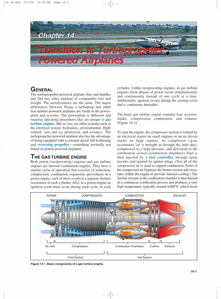
The basic gas turbine engine contains four sections:intake, compression, combustion, and exhaust.[Figure 14-1]
To start the engine, the compressor section is rotated byan electrical starter on small engines or an air drivenstarter on large engines. As compressor r.p.m.accelerates, air is brought in through the inlet duct,compressed to a high pressure, and delivered to thecombustion section (combustion chambers). Fuel isthen injected by a fuel controller through spraynozzles and ignited by igniter plugs. (Not all of thecompressed air is used to support combustion. Some ofthe compressed air bypasses the burner section and circu-lates within the engine to provide internal cooling.) Thefuel/air mixture in the combustion chamber is then burnedin a continuous combustion process and produces a veryhigh temperature, typically around 4,000°F, which heats
INTAKE COMPRESSION COMBUSTION EXHAUST
Air Inlet Compression Combustion Chambers Turbine Exhaust
Cold Section Hot Section
Figure 14-1. Basic components of a gas turbine engine.
Ch 14.qxd 5/7/04 10:08 AM Page 14-1
14-2
the entire air mass to 1,600 – 2,400°F. The mixture ofhot air and gases expands and is directed to the turbineblades forcing the turbine section to rotate, which inturn drives the compressor by means of a direct shaft.After powering the turbine section, the high velocityexcess exhaust exits the tail pipe or exhaust section.Once the turbine section is powered by gases from theburner section, the starter is disengaged, and theigniters are turned off. Combustion continues until theengine is shut down by turning off the fuel supply.
High-pressure exhaust gases can be used to providejet thrust as in a turbojet engine. Or, the gasescan be directed through an additional turbine to drive apropeller through reduction gearing, as in aturbopropeller (turboprop) engine.
TURBOPROP ENGINESThe turbojet engine excels the reciprocating engine intop speed and altitude performance. On the other hand,the turbojet engine has limited takeoff and initial climbperformance, as compared to that of a reciprocatingengine. In the matter of takeoff and initial climbperformance, the reciprocating engine is superior tothe turbojet engine. Turbojet engines are most efficientat high speeds and high altitudes, while propellers aremost efficient at slow and medium speeds (less than400 m.p.h.). Propellers also improve takeoff and climbperformance. The development of the turbopropengine was an attempt to combine in one engine thebest characteristics of both the turbojet, and propellerdriven reciprocating engine.
The turboprop engine offers several advantages overother types of engines such as:
• Light weight.
• Mechanical reliability due to relatively fewmoving parts.
• Simplicity of operation.
• Minimum vibration.
• High power per unit of weight.
• Use of propeller for takeoff and landing.
Turboprop engines are most efficient at speedsbetween 250 and 400 m.p.h. and altitudes between18,000 and 30,000 feet. They also perform well at theslow speeds required for takeoff and landing, and arefuel efficient. The minimum specific fuel consumptionof the turboprop engine is normally available in thealtitude range of 25,000 feet up to the tropopause.
The power output of a piston engine is measured inhorsepower and is determined primarily by r.p.m. andmanifold pressure. The power of a turboprop engine,however, is measured in shaft horsepower (shp). Shaft
horsepower is determined by the r.p.m. and the torque(twisting moment) applied to the propeller shaft. Sinceturboprop engines are gas turbine engines, some jetthrust is produced by exhaust leaving the engine. Thisthrust is added to the shaft horsepower to determinethe total engine power, or equivalent shaft horsepower(eshp). Jet thrust usually accounts for less than10 percent of the total engine power.
Although the turboprop engine is more complicatedand heavier than a turbojet engine of equivalent sizeand power, it will deliver more thrust at low subsonicairspeeds. However, the advantages decrease as flightspeed increases. In normal cruising speed ranges, thepropulsive efficiency (output divided by input) of aturboprop decreases as speed increases.
The propeller of a typical turboprop engine isresponsible for roughly 90 percent of the total thrustunder sea level conditions on a standard day. Theexcellent performance of a turboprop during takeoffand climb is the result of the ability of the propeller toaccelerate a large mass of air while the airplane ismoving at a relatively low ground and flight speed.“Turboprop,” however, should not be confused with“turbosupercharged” or similar terminology. Allturbine engines have a similarity to normally aspirated(non-supercharged) reciprocating engines in thatmaximum available power decreases almost as a directfunction of increased altitude.
Although power will decrease as the airplane climbsto higher altitudes, engine efficiency in terms ofspecific fuel consumption (expressed as pounds of fuelconsumed per horsepower per hour) will be increased.Decreased specific fuel consumption plus theincreased true airspeed at higher altitudes is a definiteadvantage of a turboprop engine.
All turbine engines, turboprop or turbojet, are definedby limiting temperatures, rotational speeds, and (in thecase of turboprops) torque. Depending on theinstallation, the primary parameter for power settingmight be temperature, torque, fuel flow or r.p.m.(either propeller r.p.m., gas generator (compressor)r.p.m. or both). In cold weather conditions, torquelimits can be exceeded while temperature limits arestill within acceptable range. While in hot weatherconditions, temperature limits may be exceededwithout exceeding torque limits. In any weather, themaximum power setting of a turbine engine is usuallyobtained with the throttles positioned somewhat aft ofthe full forward position. The transitioning pilot mustunderstand the importance of knowing and observinglimits on turbine engines. An overtemp or overtorquecondition that lasts for more than a very few secondscan literally destroy internal engine components.
Ch 14.qxd 5/7/04 10:08 AM Page 14-2
14-3
TURBOPROP ENGINE TYPES
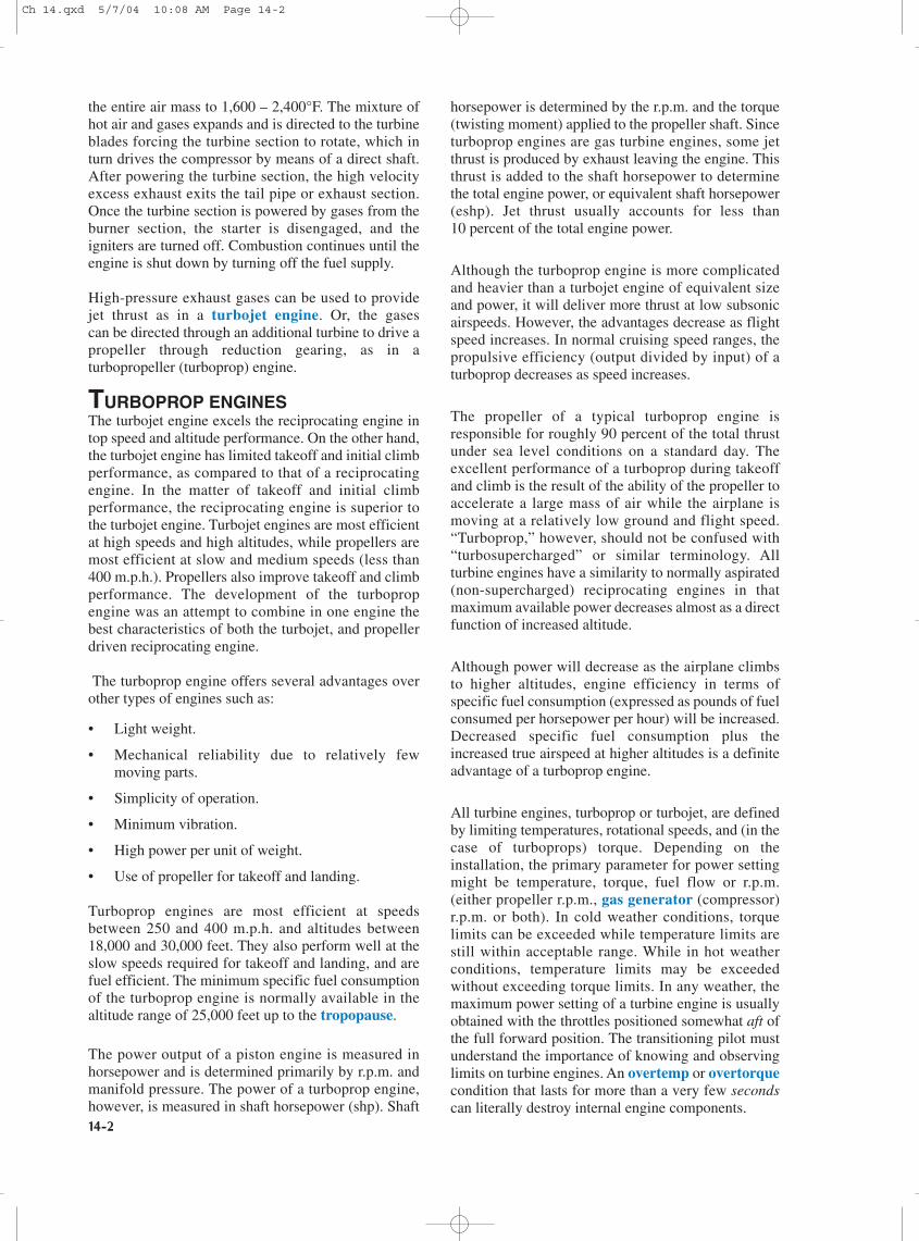
FIXED SHAFTOne type of turboprop engine is the fixed shaftconstant speed type such as the Garrett TPE331.[Figure 14-2] In this type engine, ambient air isdirected to the compressor section through the engineinlet. An acceleration/diffusion process in the two-stage compressor increases air pressure and directs itrearward to a combustor. The combustor is made up ofa combustion chamber, a transition liner, and a turbineplenum. Atomized fuel is added to the air in thecombustion chamber. Air also surrounds thecombustion chamber to provide for cooling andinsulation of the combustor.
The gas mixture is initially ignited by high-energyigniter plugs, and the expanding combustion gasesflow to the turbine. The energy of the hot, highvelocity gases is converted to torque on the main shaftby the turbine rotors. The reduction gear converts thehigh r.p.m.—low torque of the main shaft to lowr.p.m.—high torque to drive the accessories and thepropeller. The spent gases leaving the turbine aredirected to the atmosphere by the exhaust pipe.
Only about 10 percent of the air which passes throughthe engine is actually used in the combustion process.Up to approximately 20 percent of the compressed airmay be bled off for the purpose of heating, cooling,cabin pressurization, and pneumatic systems. Over
half the engine power is devoted to driving thecompressor, and it is the compressor which canpotentially produce very high drag in the case of afailed, windmilling engine.
In the fixed shaft constant-speed engine, the enginer.p.m. may be varied within a narrow range of 96percent to 100 percent. During ground operation, ther.p.m. may be reduced to 70 percent. In flight, theengine operates at a constant speed, which ismaintained by the governing section of the propeller.Power changes are made by increasing fuel flow andpropeller blade angle rather than engine speed. Anincrease in fuel flow causes an increase in temperatureand a corresponding increase in energy available to theturbine. The turbine absorbs more energy andtransmits it to the propeller in the form of torque. Theincreased torque forces the propeller blade angle to beincreased to maintain the constant speed. Turbinetemperature is a very important factor to be consideredin power production. It is directly related to fuel flowand thus to the power produced. It must be limitedbecause of strength and durability of the material in thecombustion and turbine section. The control systemschedules fuel flow to produce specific temperaturesand to limit those temperatures so that the temperaturetolerances of the combustion and turbine sections arenot exceeded. The engine is designed to operate for itsentire life at 100 percent. All of its components, suchas compressors and turbines, are most efficient whenoperated at or near the r.p.m. design point.
PlanetaryReduction Gears
AirInlet
First-StageCentrifugal
Compressor
Second-StageCentrifugal
Compressor
Reverse-FlowAnnular Combustion
Chamber
Three-StageAxial Turbine
FuelNozzle
Igniter
ExhaustOutlet
Figure 14-2. Fixed shaft turboprop engine.
Ch 14.qxd 5/7/04 10:08 AM Page 14-3
14-4
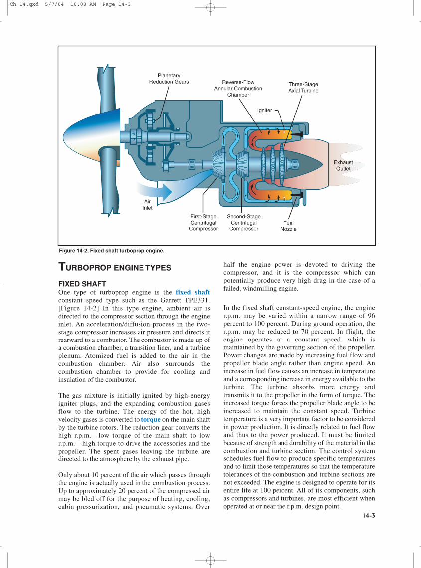
Powerplant (engine and propeller) control is achievedby means of a power lever and a condition lever foreach engine. [Figure 14-3] There is no mixture controland/or r.p.m. lever as found on piston engine airplanes.On the fixed shaft constant-speed turboprop engine,the power lever is advanced or retarded to increase ordecrease forward thrust. The power lever is also usedto provide reverse thrust. The condition lever sets thedesired engine r.p.m. within a narrow range betweenthat appropriate for ground operations and flight.
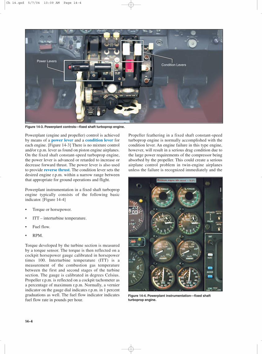
Powerplant instrumentation in a fixed shaft turbopropengine typically consists of the following basicindicator. [Figure 14-4]
• Torque or horsepower.
• ITT – interturbine temperature.
• Fuel flow.
• RPM.
Torque developed by the turbine section is measuredby a torque sensor. The torque is then reflected on acockpit horsepower gauge calibrated in horsepowertimes 100. Interturbine temperature (ITT) is ameasurement of the combustion gas temperaturebetween the first and second stages of the turbinesection. The gauge is calibrated in degrees Celsius.Propeller r.p.m. is reflected on a cockpit tachometer asa percentage of maximum r.p.m. Normally, a vernierindicator on the gauge dial indicates r.p.m. in 1 percentgraduations as well. The fuel flow indicator indicatesfuel flow rate in pounds per hour.
Propeller feathering in a fixed shaft constant-speedturboprop engine is normally accomplished with thecondition lever. An engine failure in this type engine,however, will result in a serious drag condition due tothe large power requirements of the compressor beingabsorbed by the propeller. This could create a seriousairplane control problem in twin-engine airplanesunless the failure is recognized immediately and the
Power LeversCondition Levers
Figure 14-3. Powerplant controls—fixed shaft turboprop engine.
Figure 14-4. Powerplant instrumentation—fixed shaftturboprop engine.
Ch 14.qxd 5/7/04 10:09 AM Page 14-4
14-5
affected propeller feathered. For this reason, the fixedshaft turboprop engine is equipped with negativetorque sensing (NTS).
Negative torque sensing is a condition whereinpropeller torque drives the engine and the propeller isautomatically driven to high pitch to reduce drag. Thefunction of the negative torque sensing system is tolimit the torque the engine can extract from thepropeller during windmilling and thereby prevent largedrag forces on the airplane. The NTS system causes amovement of the propeller blades automaticallytoward their feathered position should the enginesuddenly lose power while in flight. The NTS systemis an emergency backup system in the event of suddenengine failure. It is not a substitution for the featheringdevice controlled by the condition lever.
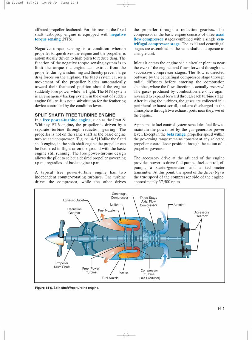
SPLIT SHAFT/ FREE TURBINE ENGINEIn a free power-turbine engine, such as the Pratt &Whitney PT-6 engine, the propeller is driven by aseparate turbine through reduction gearing. Thepropeller is not on the same shaft as the basic engineturbine and compressor. [Figure 14-5] Unlike the fixedshaft engine, in the split shaft engine the propeller canbe feathered in flight or on the ground with the basicengine still running. The free power-turbine designallows the pilot to select a desired propeller governingr.p.m., regardless of basic engine r.p.m.
A typical free power-turbine engine has twoindependent counter-rotating turbines. One turbinedrives the compressor, while the other drives
the propeller through a reduction gearbox. Thecompressor in the basic engine consists of three axialflow compressor stages combined with a single cen-trifugal compressor stage. The axial and centrifugalstages are assembled on the same shaft, and operate asa single unit.
Inlet air enters the engine via a circular plenum nearthe rear of the engine, and flows forward through thesuccessive compressor stages. The flow is directedoutward by the centrifugal compressor stage throughradial diffusers before entering the combustionchamber, where the flow direction is actually reversed.The gases produced by combustion are once againreversed to expand forward through each turbine stage.After leaving the turbines, the gases are collected in aperipheral exhaust scroll, and are discharged to theatmosphere through two exhaust ports near the front ofthe engine.
A pneumatic fuel control system schedules fuel flow tomaintain the power set by the gas generator powerlever. Except in the beta range, propeller speed withinthe governing range remains constant at any selectedpropeller control lever position through the action of apropeller governor.
The accessory drive at the aft end of the engineprovides power to drive fuel pumps, fuel control, oilpumps, a starter/generator, and a tachometertransmitter. At this point, the speed of the drive (N1) isthe true speed of the compressor side of the engine,approximately 37,500 r.p.m.
ReductionGearbox
PropellerDrive Shaft Free (Power)
Turbine CompressorTurbine
(Gas Producer)
Three StageAxial Flow
Compressor
Exhaust Outlet
Air Inlet
CentrifugalCompressor
Igniter
Fuel Nozzle
Igniter
Fuel Nozzle
AccessoryGearbox
Figure 14-5. Split shaft/free turbine engine.
Ch 14.qxd 5/7/04 10:09 AM Page 14-5
14-6
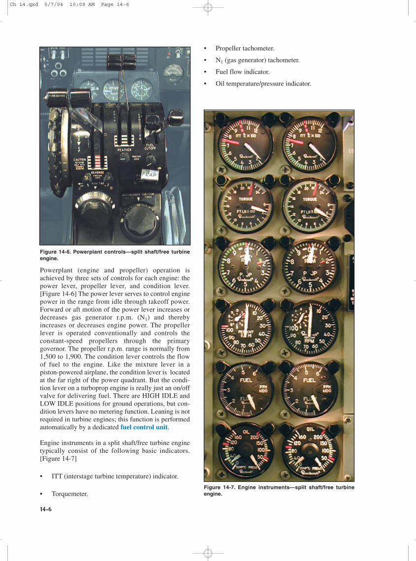
Powerplant (engine and propeller) operation isachieved by three sets of controls for each engine: thepower lever, propeller lever, and condition lever.[Figure 14-6] The power lever serves to control enginepower in the range from idle through takeoff power.Forward or aft motion of the power lever increases ordecreases gas generator r.p.m. (N1) and therebyincreases or decreases engine power. The propellerlever is operated conventionally and controls theconstant-speed propellers through the primarygovernor. The propeller r.p.m. range is normally from1,500 to 1,900. The condition lever controls the flowof fuel to the engine. Like the mixture lever in apiston-powered airplane, the condition lever is locatedat the far right of the power quadrant. But the condi-tion lever on a turboprop engine is really just an on/offvalve for delivering fuel. There are HIGH IDLE andLOW IDLE positions for ground operations, but con-dition levers have no metering function. Leaning is notrequired in turbine engines; this function is performedautomatically by a dedicated fuel control unit.
Engine instruments in a split shaft/free turbine enginetypically consist of the following basic indicators.[Figure 14-7]
• ITT (interstage turbine temperature) indicator.
• Torquemeter.
• Propeller tachometer.
• N1 (gas generator) tachometer.
• Fuel flow indicator.
• Oil temperature/pressure indicator.
Figure 14-6. Powerplant controls—split shaft/free turbineengine.
Figure 14-7. Engine instruments—split shaft/free turbineengine.
Ch 14.qxd 5/7/04 10:09 AM Page 14-6
14-7
The ITT indicator gives an instantaneous reading ofengine gas temperature between the compressorturbine and the power turbines. The torquemeterresponds to power lever movement and gives anindication, in foot-pounds (ft/lb), of the torque beingapplied to the propeller. Because in the free turbineengine, the propeller is not attached physically to theshaft of the gas turbine engine, two tachometers arejustified—one for the propeller and one for the gasgenerator. The propeller tachometer is read directly inrevolutions per minute. The N1 or gas generator is readin percent of r.p.m. In the Pratt & Whitney PT-6engine, it is based on a figure of 37,000 r.p.m. at 100percent. Maximum continuous gas generator is limitedto 38,100 r.p.m. or 101.5 percent N1.
The ITT indicator and torquemeter are used to settakeoff power. Climb and cruise power are establishedwith the torquemeter and propeller tachometer whileobserving ITT limits. Gas generator (N1) operation ismonitored by the gas generator tachometer. Properobservation and interpretation of these instrumentsprovide an indication of engine performanceand condition.
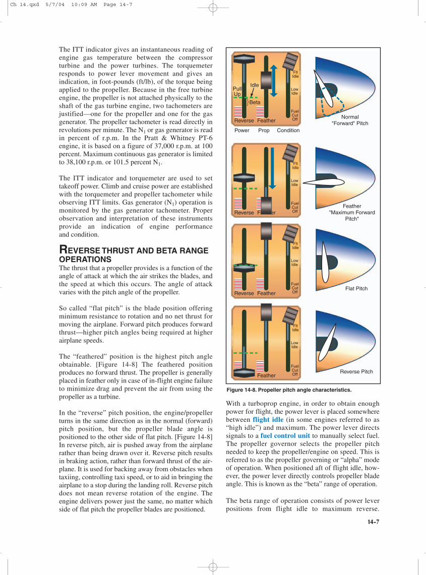
REVERSE THRUST AND BETA RANGEOPERATIONSThe thrust that a propeller provides is a function of theangle of attack at which the air strikes the blades, andthe speed at which this occurs. The angle of attackvaries with the pitch angle of the propeller.
So called “flat pitch” is the blade position offeringminimum resistance to rotation and no net thrust formoving the airplane. Forward pitch produces forwardthrust—higher pitch angles being required at higherairplane speeds.
The “feathered” position is the highest pitch angleobtainable. [Figure 14-8] The feathered positionproduces no forward thrust. The propeller is generallyplaced in feather only in case of in-flight engine failureto minimize drag and prevent the air from using thepropeller as a turbine.
In the “reverse” pitch position, the engine/propellerturns in the same direction as in the normal (forward)pitch position, but the propeller blade angle ispositioned to the other side of flat pitch. [Figure 14-8]In reverse pitch, air is pushed away from the airplanerather than being drawn over it. Reverse pitch resultsin braking action, rather than forward thrust of the air-plane. It is used for backing away from obstacles whentaxiing, controlling taxi speed, or to aid in bringing theairplane to a stop during the landing roll. Reverse pitchdoes not mean reverse rotation of the engine. Theengine delivers power just the same, no matter whichside of flat pitch the propeller blades are positioned.
With a turboprop engine, in order to obtain enoughpower for flight, the power lever is placed somewherebetween flight idle (in some engines referred to as“high idle”) and maximum. The power lever directssignals to a fuel control unit to manually select fuel.The propeller governor selects the propeller pitchneeded to keep the propeller/engine on speed. This isreferred to as the propeller governing or “alpha” modeof operation. When positioned aft of flight idle, how-ever, the power lever directly controls propeller bladeangle. This is known as the “beta” range of operation.
The beta range of operation consists of power leverpositions from flight idle to maximum reverse.
Power Prop Condition
Reverse
Beta
Idle
FeatherNormal
"Forward" Pitch
Feather"Maximum Forward
Pitch"
Flat Pitch
Reverse Pitch
FuelCutOff
Reverse
FuelCutOff
Reverse Feather
FuelCutOff
Feather
FuelCutOff
LowIdle
FltIdle
LowIdle
FltIdle
LowIdle
FltIdle
LowIdle
FltIdle
PullUp
Figure 14-8. Propeller pitch angle characteristics.
Ch 14.qxd 5/7/04 10:09 AM Page 14-7
14-8
Beginning at power lever positions just aft of flightidle, propeller blade pitch angles become progressivelyflatter with aft movement of the power lever until theygo beyond maximum flat pitch and into negative pitch,resulting in reverse thrust. While in a fixed shaft/constant-speed engine, the engine speed remainslargely unchanged as the propeller blade anglesachieve their negative values. On the split shaft PT-6engine, as the negative 5° position is reached, furtheraft movement of the power lever will also result in aprogressive increase in engine (N1) r.p.m. until amaximum value of about negative 11° of blade angleand 85 percent N1 are achieved.
Operating in the beta range and/or with reverse thrustrequires specific techniques and procedures dependingon the particular airplane make and model. There arealso specific engine parameters and limitations foroperations within this area that must be adhered to. Itis essential that a pilot transitioning to turbopropairplanes become knowledgeable and proficient inthese areas, which are unique to turbine-engine-powered airplanes.
TURBOPROP AIRPLANE ELECTRICALSYSTEMSThe typical turboprop airplane electrical system is a28-volt direct current (DC) system, which receivespower from one or more batteries and a starter/generator for each engine. The batteries may either beof the lead-acid type commonly used on piston-powered airplanes, or they may be of thenickel-cadmium (NiCad) type. The NiCad batterydiffers from the lead-acid type in that its outputremains at relatively high power levels for longerperiods of time. When the NiCad battery is depleted,however, its voltage drops off very suddenly. Whenthis occurs, its ability to turn the compressor for enginestart is greatly diminished and the possibility of enginedamage due to a hot start increases. Therefore, it isessential to check the battery’s condition before everyengine start. Compared to lead-acid batteries, high-performance NiCad batteries can be recharged veryquickly. But the faster the battery is recharged, themore heat it produces. Therefore, NiCad batteryequipped airplanes are fitted with battery overheatannunciator lights signifying maximum safe andcritical temperature thresholds.
The DC generators used in turboprop airplanes doubleas starter motors and are called “starter/generators.”The starter/generator uses electrical power to producemechanical torque to start the engine and then uses theengine’s mechanical torque to produce electrical powerafter the engine is running. Some of the DC powerproduced is changed to 28 volt 400 cycle alternatingcurrent (AC) power for certain avionic, lighting,and indicator synchronization functions. This is
accomplished by an electrical component called aninverter.
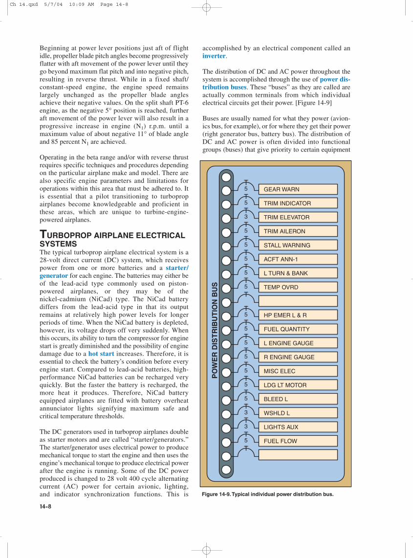
The distribution of DC and AC power throughout thesystem is accomplished through the use of power dis-tribution buses. These “buses” as they are called areactually common terminals from which individualelectrical circuits get their power. [Figure 14-9]
Buses are usually named for what they power (avion-ics bus, for example), or for where they get their power(right generator bus, battery bus). The distribution ofDC and AC power is often divided into functionalgroups (buses) that give priority to certain equipment
5 GEAR WARN
5 TRIM INDICATOR
3 TRIM ELEVATOR
5 TRIM AILERON
5 STALL WARNING
5 ACFT ANN-1
5 L TURN & BANK
5 TEMP OVRD
5 HP EMER L & R
5 FUEL QUANTITY
5 L ENGINE GAUGE
5 R ENGINE GAUGE
5 MISC ELEC
5 LDG LT MOTOR
5 BLEED L
3 WSHLD L
3 LIGHTS AUX
5 FUEL FLOW
PO
WE
R D
IST
RIB
UT
ION
BU
S
Figure 14-9.Typical individual power distribution bus.
Ch 14.qxd 5/7/04 10:09 AM Page 14-8
14-9
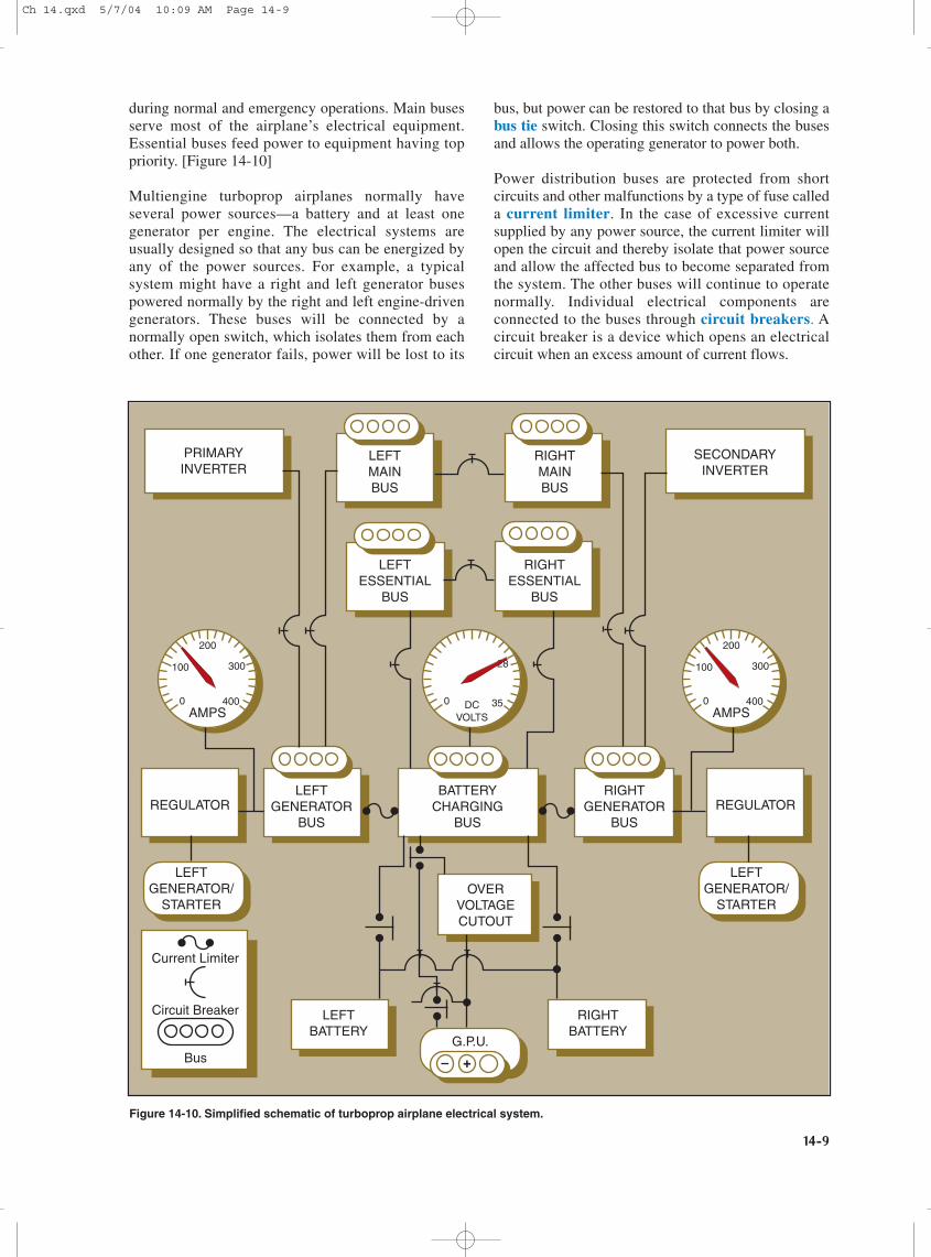
during normal and emergency operations. Main busesserve most of the airplane’s electrical equipment.Essential buses feed power to equipment having toppriority. [Figure 14-10]
Multiengine turboprop airplanes normally haveseveral power sources—a battery and at least onegenerator per engine. The electrical systems areusually designed so that any bus can be energized byany of the power sources. For example, a typicalsystem might have a right and left generator busespowered normally by the right and left engine-drivengenerators. These buses will be connected by anormally open switch, which isolates them from eachother. If one generator fails, power will be lost to its
bus, but power can be restored to that bus by closing abus tie switch. Closing this switch connects the busesand allows the operating generator to power both.
Power distribution buses are protected from shortcircuits and other malfunctions by a type of fuse calleda current limiter. In the case of excessive currentsupplied by any power source, the current limiter willopen the circuit and thereby isolate that power sourceand allow the affected bus to become separated fromthe system. The other buses will continue to operatenormally. Individual electrical components areconnected to the buses through circuit breakers. Acircuit breaker is a device which opens an electricalcircuit when an excess amount of current flows.
PRIMARYINVERTER
SECONDARYINVERTER
LEFTMAINBUS
RIGHTMAINBUS
LEFTESSENTIAL
BUS
RIGHTESSENTIAL
BUS
AMPS0
100
200
300
400 DCVOLTS
0
28
35AMPS
0
100
200
300
400
REGULATOR REGULATORLEFT
GENERATORBUS
BATTERYCHARGING
BUS
RIGHTGENERATOR
BUS
LEFTGENERATOR/
STARTER
LEFTGENERATOR/
STARTER
G.P.U.
LEFTBATTERY
RIGHTBATTERY
OVERVOLTAGECUTOUT
Current Limiter
Circuit Breaker
Bus
Figure 14-10. Simplified schematic of turboprop airplane electrical system.
Ch 14.qxd 5/7/04 10:09 AM Page 14-9
14-10
OPERATIONAL CONSIDERATIONSAs previously stated, a turboprop airplane flies just likeany other piston engine airplane of comparable sizeand weight. It is in the operation of the engines andairplane systems that makes the turboprop airplanedifferent from its piston engine counterpart. Piloterrors in engine and/or systems operation are the mostcommon cause of aircraft damage or mishap. The timeof maximum vulnerability to pilot error in any gasturbine engine is during the engine start sequence.
Turbine engines are extremely heat sensitive. Theycannot tolerate an overtemperature condition for morethan a very few seconds without serious damage beingdone. Engine temperatures get hotter during startingthan at any other time. Thus, turbine engines haveminimum rotational speeds for introducing fuel intothe combustion chambers during startup. Hyper-vigilant temperature and acceleration monitoring onthe part of the pilot remain crucial until the engine isrunning at a stable speed. Successful engine startingdepends on assuring the correct minimum batteryvoltage before initiating start, or employing a ground
power unit (GPU) of adequate output.
After fuel is introduced to the combustion chamberduring the start sequence, “light-off” and its associatedheat rise occur very quickly. Engine temperatures mayapproach the maximum in a matter of 2 or 3 secondsbefore the engine stabilizes and temperatures fall intothe normal operating range. During this time, the pilotmust watch for any tendency of the temperatures toexceed limitations and be prepared to cut off fuel tothe engine.
An engine tendency to exceed maximum startingtemperature limits is termed a hot start. The tempera-ture rise may be preceded by unusually high initial fuelflow, which may be the first indication the pilot hasthat the engine start is not proceeding normally.Serious engine damage will occur if the hot start isallowed to continue.
A condition where the engine is accelerating moreslowly than normal is termed a hung start or falsestart. During a hung start/false start, the engine may
1. Before Takeoff Checks – Completed
2. Lineup Checks – Completed Heading Bug – Runway Heading Command Bars – 10 Degrees Up
3. Power – Set 850 ITT / 650 HP Max: 923 ITT / 717.5 HP
7. Ign Ovrd – Off
6. Gear Up
8. After T/O Checklist Yaw Damp – On
9. Climb Power – Set 850 ITT / 650 HP 98 – 99% RPM
11. Climb Speed – Set Climb Checks – Completed
10. Prop Sync – On
These are merely typical procedures. The pilot maintains his or her prerogative to modify configuration and airspeeds as required by existing conditions, as long as compliance with the FAA approved Airplane Flight Manual is assured.
NOTE:
5. Rotate at 96 – 100 KIAS
4. Annunciators – Check Engine Inst. – Check
PRESSUREALTITUDE
FT
Sea Level
CLIMBSPEEDKIAS
139139134128123118113112
5,00010,00015,00020,00025,00030,00031,000
12. Cruise Checks – Completed
Figure 14-11. Example—typical turboprop airplane takeoff and departure profile.
Ch 14.qxd 5/7/04 10:09 AM Page 14-10
14-11
stabilize at an engine r.p.m. that is not high enough forthe engine to continue to run without help from thestarter. This is usually the result of low battery poweror the starter not turning the engine fast enough for itto start properly.
Takeoffs in turboprop airplanes are not made byautomatically pushing the power lever full forward tothe stops. Depending on conditions, takeoff power maybe limited by either torque or by engine temperature.Normally, the power lever position on takeoff will besomewhat aft of full forward.
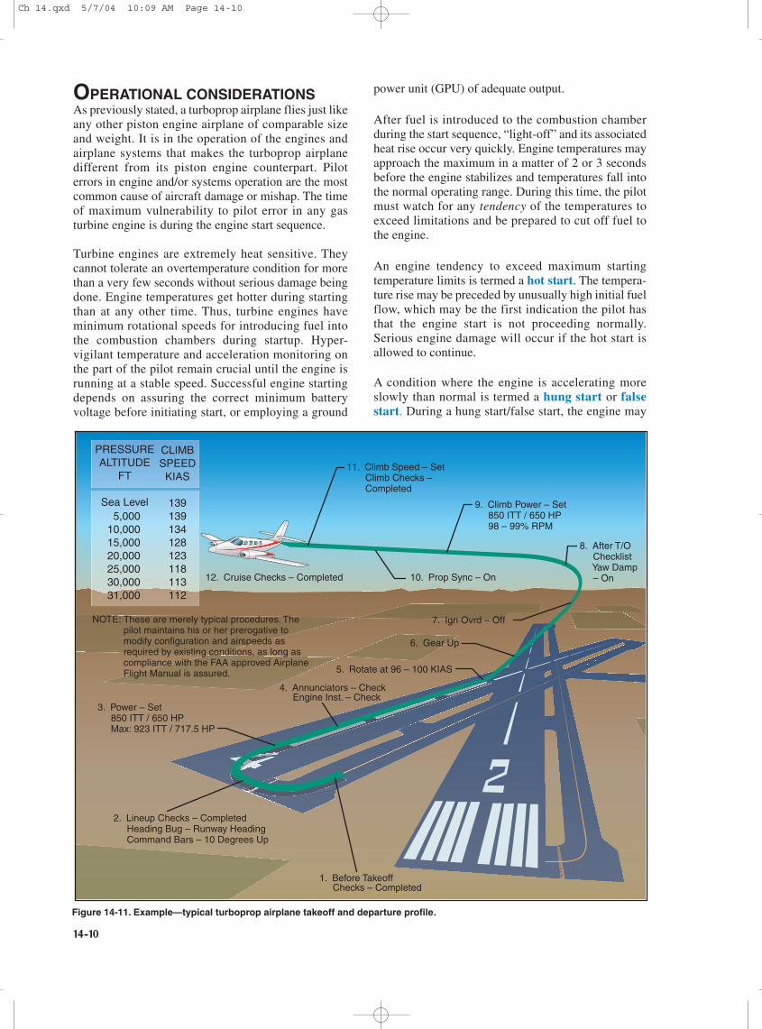
Takeoff and departure in a turboprop airplane(especially a twin-engine cabin-class airplane) shouldbe accomplished in accordance with a standard takeoffand departure “profile” developed for the particularmake and model. [Figure 14-11] The takeoff anddeparture profile should be in accordance with theairplane manufacturer’s recommended procedures asoutlined in the FAA-approved Airplane Flight Manualand/or the Pilot’s Operating Handbook (AFM/POH).The increased complexity of turboprop airplanesmakes the standardization of procedures a necessityfor safe and efficient operation. The transitioning pilotshould review the profile procedures before eachtakeoff to form a mental picture of the takeoff anddeparture process.
For any given high horsepower operation, the pilot canexpect that the engine temperature will climb asaltitude increases at a constant power. On a warm orhot day, maximum temperature limits may be reachedat a rather low altitude, making it impossible tomaintain high horsepower to higher altitudes. Also, theengine’s compressor section has to work harder withdecreased air density. Power capability is reduced byhigh-density altitude and power use may have to bemodulated to keep engine temperature within limits.
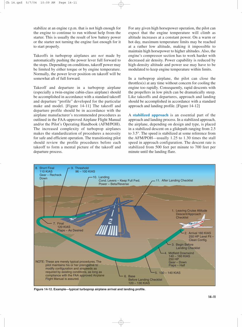
In a turboprop airplane, the pilot can close thethrottles(s) at any time without concern for cooling theengine too rapidly. Consequently, rapid descents withthe propellers in low pitch can be dramatically steep.Like takeoffs and departures, approach and landingshould be accomplished in accordance with a standardapproach and landing profile. [Figure 14-12]
A stabilized approach is an essential part of theapproach and landing process. In a stabilized approach,the airplane, depending on design and type, is placedin a stabilized descent on a glidepath ranging from 2.5to 3.5°. The speed is stabilized at some reference fromthe AFM/POH—usually 1.25 to 1.30 times the stallspeed in approach configuration. The descent rate isstabilized from 500 feet per minute to 700 feet perminute until the landing flare.
2. Arrival 160 KIAS 250 HP Level Flt – Clean Config.
3. Begin Before Landing Checklist
7. Final 120 KIAS Flaps – As Desired
6. Base Before Landing Checklist 120 – 130 KIAS
8. Short Final 110 KIAS Gear – Recheck Down
9. Threshold 96 – 100 KIAS
11. After Landing Checklist10. Landing Cond. Levers – Keep Full Fwd. Power – Beta/Reverse
These are merely typical procedures. The pilot maintains his or her prerogative to modify configuration and airspeeds as required by existing conditions, as long as compliance with the FAA approved Airplane Flight Manual is assured.
NOTE:
5. 130 – 140 KIAS
4. Midfield Downwind 140 – 160 KIAS 250 HP Gear – Down Flaps – Half
1. Leaving Cruise Altitude Descent/Approach Checklist
Figure 14-12. Example—typical turboprop airplane arrival and landing profile.
Ch 14.qxd 5/7/04 10:09 AM Page 14-11
14-12
Landing some turboprop airplanes (as well as somepiston twins) can result in a hard, prematuretouchdown if the engines are idled too soon. This isbecause large propellers spinning rapidly in low pitchcreate considerable drag. In such airplanes, it may bepreferable to maintain power throughout the landingflare and touchdown. Once firmly on the ground,propeller beta range operation will dramatically reducethe need for braking in comparison to piston airplanesof similar weights.
TRAINING CONSIDERATIONSThe medium and high altitudes at which turbopropairplanes are flown provide an entirely differentenvironment in terms of regulatory requirements,airspace structure, physiological requirements, andeven meteorology. The pilot transitioning to turbopropairplanes, particularly those who are not familiar withoperations in the high/medium altitude environment,should approach turboprop transition training with thisin mind. Thorough ground training should cover allaspects of high/medium altitude flight, including theflight environment, weather, flight planning andnavigation, physiological aspects of high-altitudeflight, oxygen and pressurization system operation,and high-altitude emergencies.
Flight training should prepare the pilot to demonstratea comprehensive knowledge of airplane performance,systems, emergency procedures, and operatinglimitations, along with a high degree of proficiency inperforming all flight maneuvers and in-flightemergency procedures.
The training outline below covers the minimuminformation needed by pilots to operate safely at highaltitudes.
a. Ground Training(1) The High-Altitude Flight Environment
(a) Airspace(b) Title 14 of the Code of Federal Regulations
(14 CFR) section 91.211, requirements foruse of supplemental oxygen
(2) Weather(a) The atmosphere(b) Winds and clear air turbulence(c) Icing
(3) Flight Planning and Navigation(a) Flight planning(b) Weather charts(c) Navigation(d) Navaids
(4) Physiological Training(a) Respiration(b) Hypoxia(c) Effects of prolonged oxygen use(d) Decompression sickness(e) Vision(f) Altitude chamber (optional)
(5) High-Altitude Systems and Components(a) Oxygen and oxygen equipment(b) Pressurization systems(c) High-altitude components
(6) Aerodynamics and Performance Factors(a) Acceleration(b) G-forces(c) MACH Tuck and MACH Critical (turbojet
airplanes)(7) Emergencies
(a) Decompression(b) Donning of oxygen masks(c) Failure of oxygen mask, or complete loss of
oxygen supply/system(d) In-flight fire(e) Flight into severe turbulence or thunder-
storms
b. Flight Training(1) Preflight Briefing(2) Preflight Planning
(a) Weather briefing and considerations(b) Course plotting(c) Airplane Flight Manual(d) Flight plan
(3) Preflight Inspection(a) Functional test of oxygen system, including
the verification of supply and pressure, reg-ulator operation, oxygen flow, mask fit, andcockpit and air traffic control (ATC)communication using mask microphones
(4) Engine Start Procedures, Runup, Takeoff, andInitial Climb
(5) Climb to High Altitude and Normal CruiseOperations While Operating Above 25,000Feet MSL
(6) Emergencies(a) Simulated rapid decompression, including
the immediate donning of oxygen masks(b) Emergency descent
(7) Planned Descents(8) Shutdown Procedures(9) Postflight Discussion
Ch 14.qxd 5/7/04 10:09 AM Page 14-12