Faa proposed rules on operation and certification of small unmanned aircraft systems

U S. Department of Transportation
Federal Aviation Administration
DOT/FAA/AAR-95/3 DOT-VNTSC-FAA-95-12
FAA AIRCRAFT CERTIFICATION
HUMAN FACTORS AND OPERATIONS CHECKLIST FOR
STANDALONE GPS RECEIVERS (TSO C129 CLASS A)
RIL 1995
PORTATIO DMINISTRA TIO Y TEM CENTER

F ~lOAREt= TL (Dq lo . ~fQ f3
~ ~~5 - c . l.
REPORT DOCUMENTATION PAGE I o~8''!J/.Prf!rmf,aa
Publ fc report ing burden for t his collection of information is estimated to average 1 hour per re~e, inel~ the time for revtewmg inftructfons ( search i~ exfstl n~ data sources, gathering end maf ntafntng the ate needed, c~letir:g and review11)9 the co lection o informa i on. Send conments regardi f'l9 this burden estimate or any: other a&~t of this collection of information, tnclucHng suggestions for reduc tng t h1s burden, to Washi~ton He~rters ~~~X~~~~fi,Diraetora!~ tg; l nfo~~!on OperationsA~ Repg~ts, 11~~5R~~~:~~onP~•Y!~rH}H~~fyfl 1~~teu~ 04, Art,l'!~egMXt
1. AGENCY USE ONLY ( leave blank) I 2. REPORT DATE 13. REPORT TYPE AND DATES COVERED April 1995 Final Report
February 1994 • March 1995
4. TITLE AND SUBTITLE 5. FUND I NG NUMBERS FAA Aircraft Certification Human Factors and Operations Checklist for Standalone GPS Receivers (TSO Cl29 Class A)
A5007/FA5E2 6 . AUTHDR(Sl M. S. Huntley, Jr. , J .W . Turner*, C. S . Donovan** , E. Madigan***
7. PERFORMING ORGANIZATION NAME(S) AND ADDRESS(ES) 8. PERFORMING ORGANIZATION U. S. Department of Transportation REPORT NUMBER
Research and Special Programs Administration DOT- VNTSC-FAA-95-12 John A. Volpe National Transportation Systems Center
Kendall Square, Cambridge, MA 02142
9. SPONSORING/MONITORING AGENCY NAME(S) AND ADDRESS(ESJ 10. SPONSORING/MONITORING U.S. Department of Transportation AGENCY REPORT NUMBER
Federal Aviation Administration DOT/FAA/AAR-95/3 Office of Aviation Research
Washington, DC 20591
11. SUPPLEMENTARY NOTES *Unisys/EG&G Dynatrend **Battelle Memorial Institute ***Battelle Memorial Institute
Volpe Center Volpe Center 505 Coll.lllbus Ave. Cambridge MA 02142 Carrbridge MA 02142 Colurbus, OH 43201
12a. DISTRIBUTION/AVAILABILITY STATEMENT 12b. DISTRIBUTION CODE
This document is available to the public through the National Technical Information Service, Springfield, VA 22161
13. ABSTRACT (Maxinun 200 words)
This docl.IJient is a check:l ist designed to assi s t Federal Aviation Acininistration (FAA) certtffcatfon persomel and g l obal posftfoning system (GPS> receiver manufacturers fn the evaluation of t he pilot~system interface characteristics of GPS receivers to be certified according to TSO C129 A1 , TRCA/00~208, and AC 20 ~ 138 . Its main focus is on contro ls, displays , and operating characteristics . The docunent is carprised of three sec tions , the Bench Test, the Flight Test, and the Appendices. The Bench Test is designed to evaluate GPS receiver design characteristics that do not require afrcraft installation and f l ights . The Flight Test is designed to . cs and ·-··-~ "~' "'~· ·-"'""'• '"' _. ..... ""~f ~'"- .. odo<M< ~-·· "'
ide reference mater i el for the spec i fic topics covered i n the checklist. DEPARTMENT QF
TP t:. .,_ T<::Dt) P T ,ll TfON
",I !'' :. ·' t .. ' 199~
Llo n •• ii Y
14 . SUBJECT TERMS FOB lOA BR, ~ChlBER PAGES
global positioning system (GPS) , human factors, ur~
certification, control s, displays, operating characteristics
17. SECURITY CLASSIFICAT ION 18. SECUR I TY CLASSIFICATION 19. SECURITY CLASSIFICATION OF REPORT OF THIS PAGE OF ABSTRACT
Unclassified Unclassified Unclassified
uou n_ n _ An - n
2a
16. PRICE CODE
20. LIMITATION OF ABSTRACT
··- -- r~-- nD ~" ~ · · -.. on•
Preseribe<fbY ANsr ·std: 239:.la 298· 102
I
I

NOTICE
This document is disseminated under the sponsorship of the Department of Transportation in the interest of information exchange. The United States Government assumes no liability for its contents or use thereof.
NOTICE
The United States Government does not endorse products or manufacturers. Trade or manufacturers' names appear herein solely because they are considered essential to the objective of this report.
IMPORTANT
Although we have attempted to make the checklist and its associated documentation technically accurate, occasional errors do occur. Should you discover a problem with the checklist please report it to:
M. Stephen Huntley, Jr. Cockpit Human Factors Program
John A. Volpe National Transportation Systems Center U.S. Department of Transportation
Kendall Square, Cambridge, MA 02142 (617) 494-2339
ii
ACKNOWLEDGEMENT
The FAA Aircraft Certification Human Factors and Operations Checklist for Standalone GPS Receivers (TSOCl29 Class A) was prepared for the Federal Aviation Administration (FAA) under contract to the U.S. Department of Transportation, Research and Special Programs Administration, John A. Volpe National Transportation Systems Center, Cockpit Human Factors Program, DTS-45.
This work was funded by the Human Perfonnance Program of the FAA's Research and Development Service as part of its cockpit human factors research activities.
iii
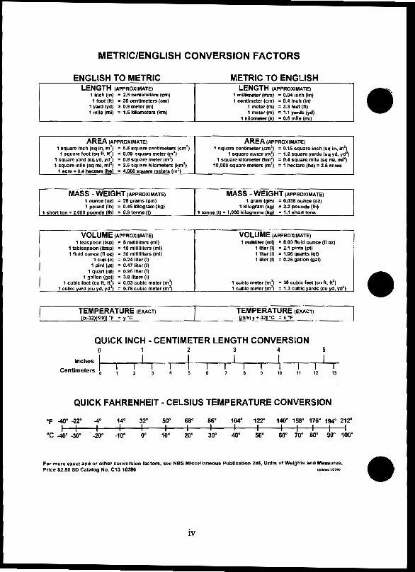
METRIC/ENGLISH CONVERSION FACTORS
ENGLISH TO METRIC LENGTH (APPROXIMATE)
1 Inch {in) = 2.5 centimeters (em) 1 foot (ft) = 30 centimeters {em)
1 yard (yd) s 0.9 meter (m} 1 mile (mi) = 1.6 kilometers (km)
AREA (APPROXIMATE) 1 square inch (sQ in, in2
) = 6.5 square centimeters (cm2)
1 square foot (sq ft, ff) = 0.09 square meter (m2)
1 square yard (sq yd, yd2) = 0.8 square meter (m2
)
1 square mile (sq mi, mi2) = 2.6 square kilometers (km2
)
" 1 acre= 0.4 hectare {he) = 4,000 square meters (m2)
MASS -WEIGHT (APPROXIMATE)
VOLUME (APPROXIMATE) 1 teaspoon (tsp) • 5 milliliters (ml}
1 tablespoon (tbsp) = 15 milliliters (ml) 1 fluid ounce (H oz) = 30 milliliters (ml)
1 cup (c) = 0.24 liter (1) 1 pint (pt) = 0.47 liter (I)
1 quart (qt) = 0.96 liter (I) 1 gallon (gal) = 3.8 liters (I)
1 cubic foot (cu ft, ft3) = 0.03 cubic meter (m3
)
1 cubic yard (cu yd, yd3) = 0.76 cubic meter (m3
)
METRIC TO ENGLISH LENGTH (APPROXIMATE)
1 millimeter (mm) = 0.04 inch (In) 1 centimeter (em) = 0.4 Inch (in) '
1 meter (m) = 3.3 feet (It) 1 meter (m) 11:: 1.1 yards (yd)
1 kilometer {k) = 0.6 mile (mi)
AREA (APPROXIMATE) 1 squal"e centimeter (cm 2
) = 0.16 square inch (sq in, tn2~ 1 square meter (m2
) = 1.2 square yards (aq yd, yd } 1 square kilometer (km2
} a 0.4 square mile (sq ml, mi2)
10,000 square meters (m2) = 1 hectare (he)= 2.5 acres
VOLUME (APPROXIMATE) 1 milliliter (ml) = 0.03 fluid ounce (fl oz)
1 liter (I) • 2.1 pints (pi) 1 liter (I) • 1.06 quarts (qt) 1 liter (I) = 0.26 gallon (gal}
1 cubic meter (ml) • 36 cubic feet (cu ft, ft3) 1 cubic meter (m3
) = 1.3 cubic;_y_M_(IS (cu yd, yd3)
QUICK INCH - CENTIMETER LENGTH CONVERSION 0 1 2 3 4
Inches I I I I I I centimeters I I I I I I I I 1 I I I
0 10 11 12 13
QUICK FAHRENHEIT- CELSIUS TEMPERATURE CONVERSION
"F -40" -22" -4" 14" 32° so• 68" 86" 104" 122" 140" 158" 176° 194" 212"
•c -40" -30" · -2o· -10" o· 10" 20" 30" 40" so· so· 70" so• so· 100"
For more exact and or other convc~lon factors, see NBS Miscellaneous Publication 286, Units of Weights and Measures. Price $2.50 SO Catalog No. C13 10286 ~ 112liN
iv
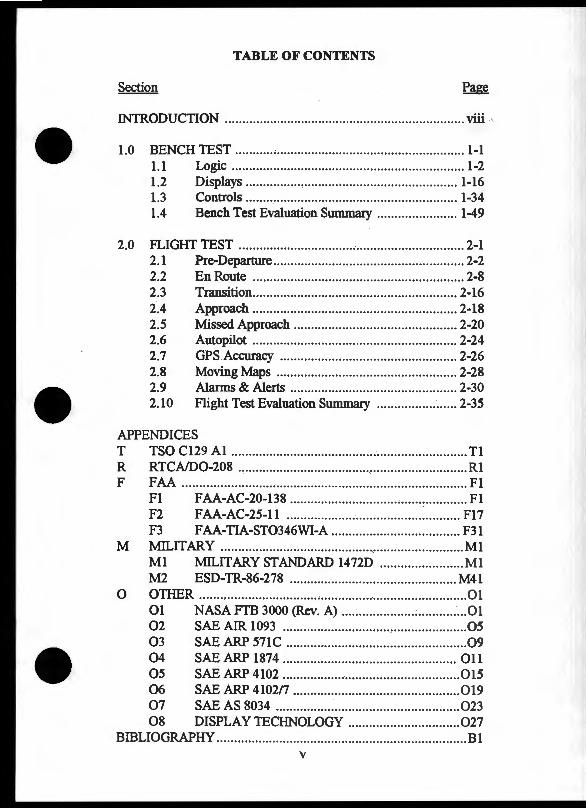
TABLE OF CONTENTS
Section Page
INI'R.ODUCTION .... ....... ..... .. ........... .. ... ..... ....... .. ...... ............. .. viii
1.0 BENCH TEST ............................... .. ........................... .. ... . 1-1 1.1 Logic ....... .................. ...... ...... ................... ........... 1-2 1.2 Displays ....... .... ......... ...... .. .... .... .. ................. ...... 1-16 1.3 Controls ................................. ......... .. .. .. ............. 1-34 1.4 Bench Test Evaluation Summary ...... .... ... ....... ... 1-49
2.0 FLIGHT TEST ....... ................... .. ... ........... ... ... .. ............... 2-1 2.1 Pre-Departure ..... .... ......... .. .... ............ ... .. .............. 2-2 2.2 En Route ...................... ... ..... ..................... .. ..... .. . 2-8 2.3 Transition ...... ...... ... .. ... .... .............................. .. ... 2-16 2.4 Approach ................ ........ .. ......................... ........ 2-18 2.5 Missed Approach ..... ... ........... ..... ... .. ... .. .. .. ...... ... 2-20 2.6 Autopilot ..... .. ................................... ................. 2-24 2. 7 GPS Accuracy ...... ...... ....... .. .... .......................... 2-26 2.8 Moving Maps ........ .. ... ....... ... ............. .. .............. 2-28 2.9 Alarms & Alerts .................... .. ... ..... ............... .. . 2-30 2.10 Flight Test Evaluation Summary ....... .. .. .......... .. 2-35
APPENDICES T TSO C129 AI ...... ..................... ..... ..... ................... ............ Tl R RTCA/D0-208 ................... ........... ... .. .............. ............ ..... Rl F FAA .............................................. ..... ... ... ....... .. ................ Fl
Fl FAA-AC-20-138 .................. ... .. .. ... ... •.................. . Fl F2 FAA-AC-25-11 ........... .. .. ...... .. ........................... F17 F3 FAA-TIA-ST0346WI-A .. .. ..... ... .. .............. ......... F31
M l'v1ILIT ARY ......... .... ...................... .................. .... .. ........... Ml Ml l'v1ILITARY STANDARD 1472D .................... ... . Ml M2 ESD-TR-86-278 .. ....... ...... ......... ...... .... ....... .. .. ... M41
0 OTHER ........... ............. ......... .. ... ................. ... ............. ...... 01 01 NASA FTB 3000 (Rev. A) ......... .. ............. ............ 01 02 SAE AIR 1093 ... ......... ....................... .. ................ 05 03 SAE ARP 571C ............ .................................... .. .. 09 04 SAE ARP 1874 .......... ............. ...... .................. ... 011 05 SAE ARP 4102 ................. ................. ................. 015 06 SAE ARP 4102n .. .... .. .... .. .... ........................ .. ... . 019 07 SAE AS 8034 ........ .... ...... ............. .. ...... ... ........ ... 023 08 DISPLAYTECHNOLOGY ..... ............ ......... .. .. .. 027
BffiLIOGRAPHY ..... .. ... .... .... ...... .. ... .. ....... ... ...................... ... .... .. Bl v
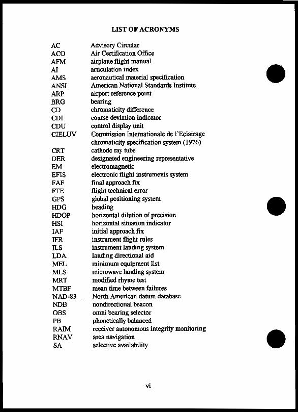
AC ACO AFM AI AMS ANSI ARP BRG CD CDI CDU CIELUV
CRT DER EM EFIS FAF fTE GPS HOG HOOP HSI IAF IFR as LOA MEL MLS MRT MTBF NAD-83 NDB OBS PB RAIM RNAV SA
LIST OF ACRONYMS
Advisory Circular Air Certification Office airplane flight manual articulation index aeronautical material specification American National Standards Institute airport reference point bearing chromaticity difference course deviation indicator control display unit Commission Internationale de I 'Eclairage chromaticity specification system (1976) cathode ray tube designated engineering representative electromagnetic electronic flight instruments system final approach fix flight technical error global positioning system heading horizontal dilution of precision horizontal situation indicator initial approach fix instrument flight rules instrument landing system landing directional aid minimum equipment list microwave landing system modified rhyme test mean time between failures North American datum database nondirectional beacon omni bearing selector phonetically balanced receiver autonomous integrity monitoring area navigation selective availability
vi
SAE SDF SID STAR STC TACAN TAE TC TSO VFR VNAV VOR VORTAC WGS-84 XTE
LIST OF ACRONYMS (€ontinued)
Society of Automotive Engineers standiford field standard instrument departure standard terminal arrival route supplemental type certificate tactical aircraft control and navigation track angle error type certificate Technical Standard Order visual flight rules vertical navigation very high frequency omni-directional radio range combined VOR and T ACAN navigational facility world geodetic survey database cross track error
vii
FAA AIRCRAFT CERTIFICATION HUMAN FACTORS AND OPERATIONS CHECKLIST FOR STANDALONE
GPS RECEIVERS (TSO-C129 CLASS A)
INTRODUCTION
This checklist is designed to assist FAA certification personnel and GPS receiver manufacturers in the evaluation of the pilot-system interface characteristics of GPS receivers to be certified according to TSO Cl29 Al, RTCA/D0-208, and AC 20-138. Controls, displays, and operating characteristics are the main focus of this checklist. Presently the checklist does not address receiver hardware and functional characteristics that do not require direct pilot involvment, such as data reliability, failure protection, and data continuity during aircraft maneuvering.
This checklist is arranged in three major sections: Bench Test, Flight Test, and Appendices. The Bench Test is designed to evaluate GPS receiver design characteristics that do not require aircraft installation and flight. Three topic areas are covered in the Bench Test: Logic, Displays, and Controls. The Logic section focuses on waypoint entry and flight planning functions. The Display section covers alarms and alerts, moving maps, and general display characteristics. The Controls section covers knob, button, keyboard, coding, and labeling design characteristics.
The Flight Test is designed to evaluate receiver design characteristics and functions under actual flight conditions (e.g., Waypoint Sequencing & Turn Anticipation). The Flight Test is provided in the context of Departure, En Route, Transition, Approach and Missed Approach flight segments. In addition, Autopilot, GPS Accuracy, Moving Map, Alarms, and Alerts are covered.
The Appendices are designed to provide reference material for the specific topics covered in the checklist. It should be noted that the reference materials (including the TSO Cl29 Al and the RTCA/D0-208) are not complete, but contain only the extracted portions from the original documents which are directly relevant to the specific checklist items.
viii
INSTRUCTIONS
Evaluation material. Evaluation topics are presented as a set of facing pages. The left-hand page lists the section, evaluation title, purpose, test procedure, and evaluation considerations. The Purpose describes what the evaluation topic covers. The Test Procedure provides the user with a suggested method of examining a particular function or characteristic of the receiver. Evaluation Considerations are given to assist in decision making.
Scoring. comments. and references. On the right-hand page, an evaluation box is given that corresponds to the letter of the evaluation consideration (e.g. A, E, or EM). Each evaluation box contains a space to indicate either a "fail", "pass with exception", or "pass" score. The particular rating chosen is dependent upon the requirements ~ified in the TSO C129 AI, AC 20-138, and RTCA/D0-208 documents and sound engineering judgment as determined by the certification specialist. In addition, a space is provided for comments, concerns, or notes.
The lower portion of the right-hand page contains a listing of information that was used to develop the evaluation material on the left-hand page. Information relevant to the TSO C129 AI and/or the RTCA/D0-208 is listed under the Requirements header. Military, FAA (e.g., AC 20-138), and other human factors related information sources are listed under the Guidelines header. All referenced material is provided in the appendices. Additional discussions can be found in McAnulty (1994) "A Review of Principles and Guidelines for the Design of Controls and Displays for Standalone GPS and LORAN Receivers."
Requirements and guidelines are cross-referenced in bold with the information contained on the left-hand page. For each requirement or guideline listed, three pieces of information are provided to assist the user during the evaluation. First, a cross-reference number is provided that corresponds with the evaluation material on the left-hand page. Second, the page number where the requirement or guideline information can be found in the appendix is given. Lastly, the appendix and section are listed.
ix
Example of Cross Referencing:
"(1) (p. R3), R 2.2.1.4" refers to cross referenced item number one, page R3, section 2.2.1.4, of appendix R. If the user wants direct access to the reference material cross referenced with a (1), the page number and section of the appendix are readily available.
SUIIlliUlty scoring sheet. A summary scoring sheet is provided at the end of each test section. The summary scoring sheet lists the TSO Cl29 AI and RTCA/D0-208 requirements that were addressed and cross-references them with the corresponding checklist evaluation topic and page number. In addition, "fail", "pass with exception", and "pass" score boxes are given to provide the user with an overall perspective of the evaluation scores. Any areas of concern will quickly be noticeable because the scores would not line up in the rightmost column (i.e., pass).
X

t; w 1-:::1: (.) z w £ll
.,...

1.0 BENCH TEST ....... ......... ............................ .. .... ....... .... ..... 1-1
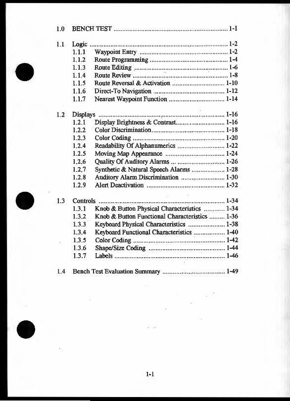
1.1 Logic .......... .......... .. .... ...... ........ ... ...... ..... ........................ .. 1-2 1.1.1 Waypoint Entry .... ............................ .. ........ ......... 1-2 1.1.2 Route Programming .......................... .. ... ...... ...... .. 1-4 1.1.3 Route Editing .... ........ ........ ..... ...... .. ................... .. 1-6 1.1.4 Route Review ....... .... .. ............. ..... ..... ........ .... ....... 1-8 1.1.5 Route Reversal & Activation .. ........ .......... .. ....... . 1-10 1.1.6 Direct-To Navigation .. ...... .. ....... .... ........ .. ..... ..... 1-12 1.1. 7 Nearest Waypoint Function ....... ...... ..... ......... ..... 1-14
1.2 Displays ........ .. ...... ... ...... ... ..... ..... .... .. ...... ....... .. .. ............ 1-16 1.2.1 Display Brightness & Contrast .. .. ....... ... .. ........ .... 1-16 1.2.2 · Color Discrimination ... ..... ... .... ........ ..... ..... ......... 1-18 1.2.3 Color Coding .. ... ... ... .. .. .. ...... ...... .. .... .... ..... .. ....... 1-20 1.2.4 Readability Of Alphanumerics ....... .... ... ...... ... ... . 1-22 1.2.5 Moving Map Appearance ...... ..... ... .. ....... ........... 1-24 1.2.6 Quality Of Auditory Alanns .... ......................... . 1-26 1.2.7 Synthetic & Natural Speech Alanns ... ......... ...... . 1-28 1.2.8 Auditory Alarm Discrimination ....... , ... .. .......... .. 1-30 1.2.9 Alert Deactivation ............... ..... ........ .......... ..... .. 1.-32
1.3 Controls ......... ... ....... .. ............ .. .... ..... .......... .... ..... ......... . 1-34 1.3.1 Knob & Button Physical Characteristics ............ 1-34 1.3.2 Knob & Button Functional Characteristics .. .... .. . 1-36 1.3.3 Keyboard Physical Characteristics ... .... ... ........... 1-38 1.3.4 Keyboard Functional Characteristics ... ........ .. ..... 1-40 1.3.5 Color Coding ..... .. ... .. .. .... ... ........... ... : .. .... .. .... ... .. 1-42 1.3.6 Shape/Size Coding .. ... ................. .... ...... ..... ... .... 1-44 1.3.7 Labels ... ............ .. ... ...... .... ...... .... ... : ... .. . : .. ...... ... .. 1-46
1.4 Bench Test Evaluation Summary .. ... .... .. .... ....... ... .... ....... 1-49
1-1
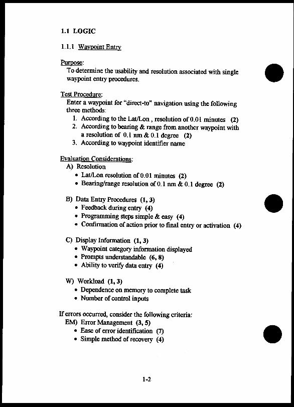
1.1 LOGIC
1.1.1 Waypoint Entry
Purpose: To determine the usability and resolution associated with single waypoint entcy procedures.
Test Procedure: Enter a waypoint for "direct-to" navigation using the following three methods:
1. According to the Lat/Lon, resolution ofO.Ol minutes (2) 2. According to bearing & range from another waypoint with
a resolution of 0.1 nm & 0.1 degree (2) 3. According to waypoint identifier name
Evaluation Considerations: A) Resolution
• Lat/Lon resolution ofO.Ol minutes (2) • Bearing/range resolution of 0.1 nm & 0.1 degree (2)
B) Data Entcy Procedures (1, 3) • Feedback during entcy (4) • Programming steps simple & easy (4) • Confirmation of action prior to final entcy or activation (4)
C) Display Information (1, 3) • Waypoint category information displayed • Prompts understandable (6, 8) • Ability to verify data entcy (4)
W) Workload (1,3) • Dependence on memory to complete task • Number of control inputs
If errors occurred, consider the following criteria: EM) Error Management (3, 5)
• Ease of error identification (7) • Simple method of recovery (4)
1-2
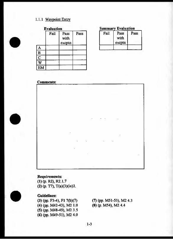
1.1.1 Waypoint Entry
Evaluation Fail Pass
with excptn
A B c w EM
Comments:
Requirements: (1) (p. R2), R2.1.7 (2) (p. T7), T(a)(3)(ix)2.
Guidelines:
Pass
(3) (pp. F3-4), Fl 7(b)(7) (4) (pp. M42-43), M2 1.0 (5) (pp. M48-49), M2 3.5 (6) (pp. M49-51), M2 4.0
1-3
s Evatuauon Pass Pass with
excptn
(7) (pp. MSI-53), M2 4.3 (8) (p. MS4), M2 4.4
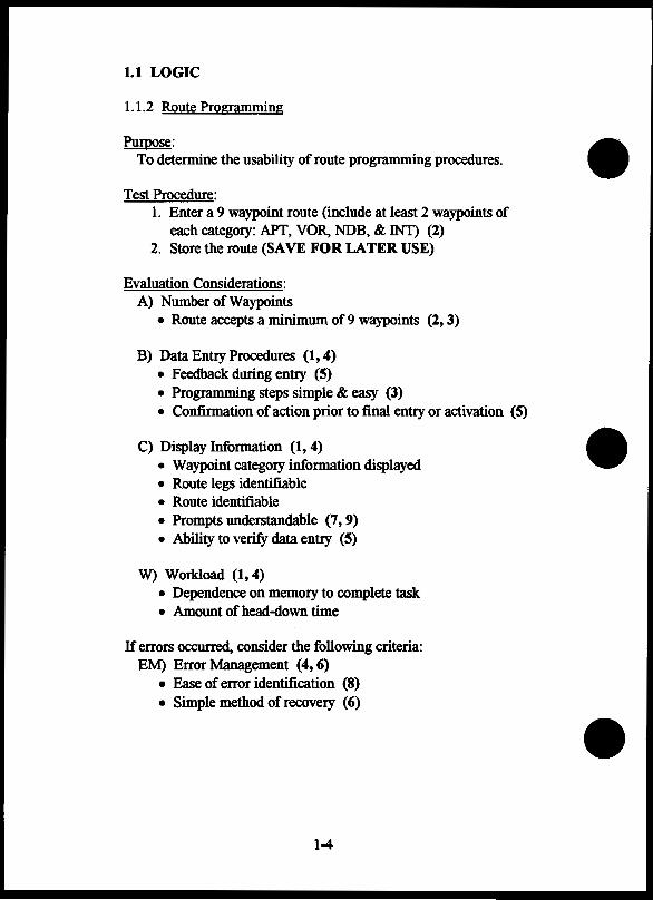
1.1 LOGIC
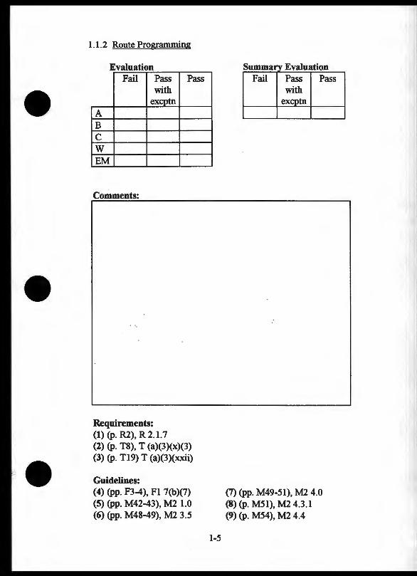
1.1.2 Route Programming
Purpose: To determine the usability of route programming procedures.
Test Procedure: 1. Enter a 9 waypoint route (include at least 2 waypoints of
each category: APT, VOR. NDB, & INT) (2) 2. Store the route (SAVE FOR LATER USE)
Evaluation Considerations: A) Number ofWaypoints
• Route accepts a minimum of 9 waypoints (2, 3)
B) Data Entry Procedures (1, 4) • Feedback during entry (5) • Programming steps simple & easy (3) • Confirmation of action prior to final entry or activation (5)
C) Display Information (1, 4) • Waypoint category information displayed • Route legs identifiable • Route identifiable • Prompts understandable (7, 9) • Ability to verify data entry (5)
W) Workload (1, 4) • Dependence on memory to complete task • Amount of head-down time
If errors occurred, consider the following criteria: EM) Error Management (4, 6)
• Ease of error identification (8) • Simple method of recovery (6)
1-4
1.1.2 Route Programming
Evaluation Fail Pass Pass
with excptn
A B c w EM
Comments:
Requirements: (1) (p. R2), R2.1.7 (2) (p. T8), T (a)(3)(x)(3) (3) (p. T19) T (a)(3)(xxii)
Guidelines: (4) (pp. F3-4), F1 7(b)(7) (5) (pp. M42-43), M2 1.0 (6) (pp. M48-49), M2 3.5
1-5
--~--- -·------...... -Fail Pass Pass
with exeptn
(7) (pp. M49-51), M2 4.0 (8) (p. M51), M2 4.3.1 (9) (p. M54), M2 4.4
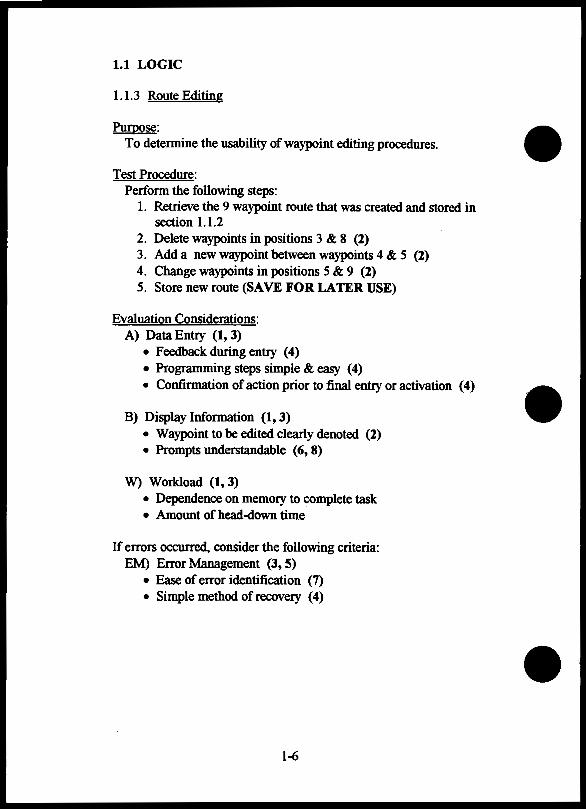
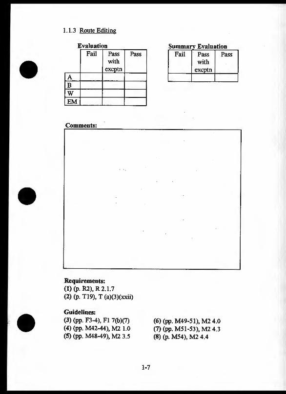
1.1 LOGIC
1.1.3 Route Editing
Put:pose: To determine the usability ofwaypoint editing procedures.
Test Procedure: Perform the following steps:
1. Retrieve the 9 waypoint route that was created and stored in section 1.1.2
2. Delete waypoints in positions 3 & 8 (2) 3. Add a new waypoint between waypoints 4 & 5 (2) 4. Change waypoints in positions 5 & 9 (2) 5. Store new route (SAVE FOR LATER USE)
Evaluation Considerations: A) Data Entry (1, 3)
• Feedback during entry (4) • Programming steps simple & easy (4) • Confirmation of action prior to final entry or activation (4)
B) Display Information (1, 3) • Waypoint to be edited clearly denoted (2) • Prompts understandable (6, 8)
W) Workload (1, 3) • Dependence on memory to complete task • Amount of head-down time
If errors occurred, consider the following criteria: EM) Error Management (3, 5)
• Ease of error identification (7) • Simple method ofrecovery (4)
1-6
1.1.3 Route Editing
Evaluation Fail Pass Pass
with excptn
A B w EM
Comments:
Requirements: (1) (p. R2), R 2.1. 7 (2) (p. T19), T (a)(3)(xxii)
Guidelines: (3) (pp. F3-4), Fl 7(b)(7) (4) (pp. M42-44), M2 1.0 (5) (pp. M48-49), M2 3.5
1-7
-- -- ----"""'--Fail Pass Pass
with exCQ!!!_ ---- - u -
(6) (pp. M49-51), M2 4.0 (7) (pp. M51-53), M2 4.3 (8) (p. M54), M2 4.4
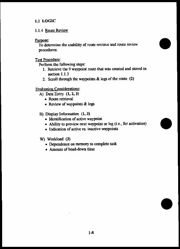
1.1 LOGIC
1.1.4 Route Review
Purpose: To determine the usability of route retrieve and route review procedures.
Test Procedure: Perform the following steps:
1. Retrieve the 9 waypoint route that was created and stored in section 1.1.3
2. Scroll through the waypoints & legs of the route (2)
Evaluation Considerations: A) Data Entry (1, 2, 3)
• Route retrieval • Review of waypoints & legs
B) Display Information (1, 3) • Identification of active waypoint • Ability to preview next waypoint or leg (i.e., for activation) • Indication of active vs. inactive waypoints
W) Workload (3) • Dependence on memory to complete task • Amount of head-down time
1-8

1.1.4 Route Review
Evaluation -------- _., ___ .,_""_
Fail Pass Pass Fail Pass Pass with with
excptn excptn A B w
Comments:
Requirements: (1) (p. R4), R2.2.1.7 (2) (p. Tl9), T (a)(3)(xxii)
Guidelines: (3) (pp. F3-4), Fl 7(b)(7)
1-9
1.1 LOGIC
1.1.5 Route Reversal & Activation
Purpose: To determine the usability of route reversal and route activation procedures.
Test Procedure: Perform the following steps:
1. Retrieve the 9 waypoint route that was created and stored in section 1.1.3
2. Reverse the route (if possible) 3. Activate the route
Evaluation Considerations: A) Data Entry {2, 3)
• Route reversal function • Route activation • Ability to confirm route prior to route activation (4)
B) Display Information (3) • Distinction between "old" & "new" routes • Identification of active waypoint • Bearing to active waypoint • Distance to active waypoint • Display of CDI information
W) Workload (1, 2, 3) • Dependence on memory to complete task • Amount of head-down time
1-10
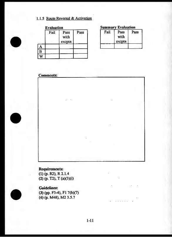
1.1.5 Route Reversal & Activation
Evaluation Fail Pass
with exeptn
A B w
Comments:
Requirements: (1) (p. R2), R 2.1.4 (2) (p. T2), T (a)(3)(i)
Guidelines:
Pass
(3) (pp. F3-4), Fl 7(b)(7) (4) (p. M48), M2 3.5.7
1-11
-------- _,. ___ ., ___ Fail Pass Pass
with excptn
1.1 LOGIC
1.1.6 Direct-To Navigation
Purpose: To detennine the usability of the Direct-To function.
Test Procedure: Perform the following steps:
1. Enter a waypoint to navigate to 2. Activate Direct-To function
Evaluation Considerations: A) Data Entry (1, 3)
• Direct-To function activated with a single control action (2)
• Waypoint entry • Ability to confirm waypoint prior to activation (4)
B) Display Information (1, 3) • Identification of active waypoint • Bearing to active waypoint • Distance to active waypoint • CDI information display
W) Workload (3) • Dependence on memory to complete task • Amount of head-down time
1-12
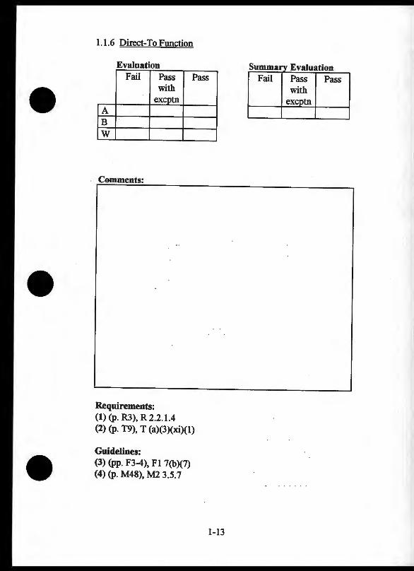
1.1.6 Direct-To Function
Evaluation Fail Pass Pass
with excptn
A B w
Comments:
Requirements: (1) {p. R3), R 2.2.1.4 (2) {p. T9), T (a)(3)(xi)(l)
Guidelines: (3) {pp. F3-4), Fl 7(b)(7) (4) {p. M48), M2 3.5.7
1-13
~ummarv Evaluation Fail Pass Pass
with '-------1 excptn
1.1 LOGIC
1.1.7 Nearest Waypoint Function
Purpose: To determine the usability of the nearest waypoint function.
Test Procedure: Perform the following steps:
1. Activate the nearest waypoint function and select a waypoint from each category (e.g., APT, VOR, NDB, & INT)
Evaluation Considerations: A) Data Entry (1, 2, 3)
• Nearest waypoint activation function • Selectability of waypoints • Waypoint confirmation prior to activation (4)
B) Display Information (3) • Identification of active/selected waypoint • Identification of waypoint category • Critical information displayed (e.g., additional runways,
communication frequencies, etc.)
W) Workload (1, 2, 3) • Dependence on memory to complete task • Amount of head-down time
1-14
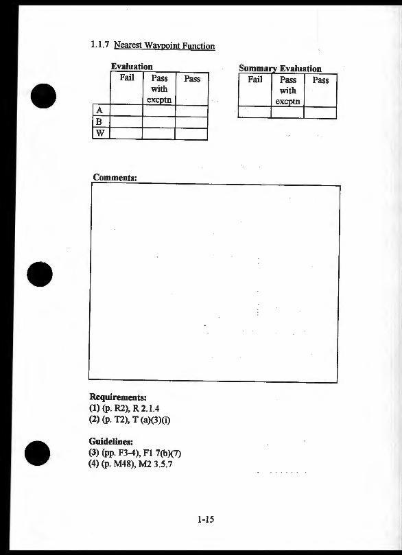
1.1.7 Nearest Wavooint Function
Evaluation Fail Pass
with exeptn
A B w
Comments:
Requirements: (1) (p. R2), R 2.1.4 (2) (p. T2), T (a)(3)(i)
Guidelines: (3) (pp. F3-4), Fl 7(b)(7) (4) (p. M48), M2 3.5.7
Pass
1-15
~umma Evaluation Fail Pass Pass
with excptn
1.2 DISPLAYS
1.2.1 Display Brightness & Contrast
Purpose: To evaluate display brightness and contrast under various ambient lighting conditions.
Test Procedure: (3, 4) Examine the display information under the following conditions:
1. Dark room (no lights, curtains closed) 2. Room lighting & reflections (lights on, curtains open,
observer facing window) 3: Room lighting & a glare source (lights on, curtains open,
and sunlight shining on display)
Evaluation Considerations: A) Brightness & Contrast Adjustments for: (1, 2, 3, 4, 6, 8)
• Darkroom • Lighting with reflections • Lighting with glare source
B) Automatic Brightness Control (6, 8) • Rapid changes when ambient light is increased • Slow changes when ambient light is decreased
C) Reflection Level (3, 4, 5, 7, 9) • No distraction • No interference with displayed information
1-16
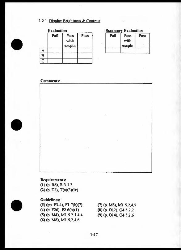
1.2.1 Disolay Brightness & Contrast
Evaluation --- - - - - ---
Fail Pass Pass with
excptn A B c
Comments:
Requirements: (I) (p. R8), R 3 .1.2 (2) (p. T2), T(a)(3)(iv)
Guidelines: (3) (pp. F3-4), Fl 7(b)(7) (4) (p. F26), F2 6(b)(1) (5) (p. M4), M1 5.2.1.4.4 (6) (p. M8), Ml 5.2.4.6
1-17
:summa Evaluation Fail Pass
with excptn
(7) (p. M8), Ml 5.2.4.7 (8) (p. 012), 04 5.2.2 (9) (p. 014), 04 5.2.6
Pass

1.2 DISPLAYS
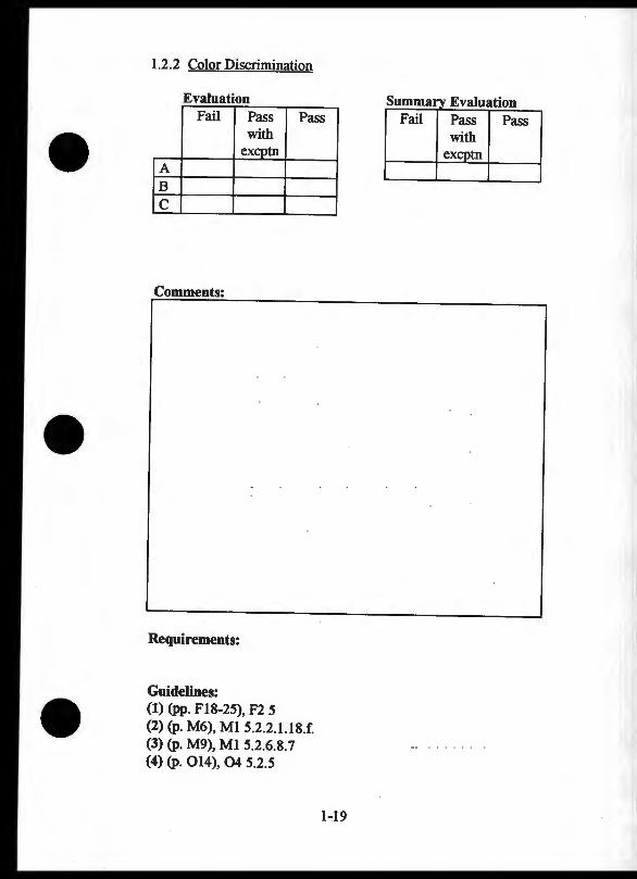
1.2.2 Color Discrimination
Purpose: To determine if colors on the display are discriminable.
Test Procedure: If possible, simulate a flight along a route and scan through the pages of the route, waypoint, navigation, and system modes. Evaluate the differences between the colors used on the display.
Evaluation Considerations: A) Color Differences (1)
• Colors appear different from each other (e.g., does yellow look different from green) (4)
B) Coding (1) • Small symbol discriminability • Small alphanumeric discriminability
C) Safety Critical Features (1) • Color coding discriminability (Note: Some older pilots
report difficulty seeing blue- and magenta- coded features on displays) (2, 3)
1-J8
1.2.2 Color Discrimination
Evaluation Fail Pass Pass
with excptn
A B c
Comments:
Requirements:
Guidelines: (1) (pp. F18-25), F2 5 (2) (p. M6), Ml 5.2.2.1.18.f. (3) (p. M9), Ml 5.2.6.8.7 (4) (p. 014), 04 5.2.5
1-19
s Eval ummarv ~- - -- - -
Fail Pass Pass with
excptn
I
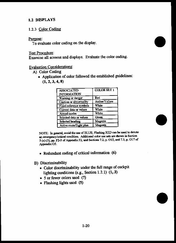
1.2 DISPLAYS
1.2.3 Color Coding
Puroose: To evaluate color coding on the display.
Test Procedure: Examine all screens and displays. Evaluate the color coding.
Evaluation Considerations: A) Color Coding
• Application of color followed the established guidelines: (1, 2, 3, 4, 8)
ASSOCIATED COLOR SET 1 INFORMATION Warning or dan11:er Red Caution or abnonnalitv Arnber/Y ell ow Fixed reference symbols White Current data or values White
Armed modes White Selected data or values Green
Selected heading Ma11:enta Active route/flight plan Ma11:enta
NOTE: In general, avoid the use of BLUE; Flashing RED can be used to denote an emergency/critical condition. Additional color use sets are shown in Section S (a) (3), pp. Fl-3 of Appendix F2, and Sections 7.2, p. 01!1, and 7.3, p. 017 of Appendix OS.
• Redundant coding of critical information (6)
B) Discriminability • Color discriminability under the full range of cockpit
lighting conditions (e.g., Section 1.2.1) (1, 3) • 5 or fewer colors used (7) • Flashing lights used (5)
1-20

1.2.3 Color Coding
Evaluation Fail Pass Pass
with excotn
lA IB
Comments:
Requirements:
Guidelines: (1) (pp. F3-4), F1 7(b)(7) (2) (pp. F18-19), F2 5(a)(2-3) (3) (p. F26), F2 6(b)(l) (4) (p. M5), M1 5.2.2.1.18
1-21
:summa Eval - ~ ~- - - -- -- - -
Fail Pass Pass with
(5) (p. M6), M1 5.2.2.1.19 (6) (p. 016), 05 7.1.2 (7) (p. 016), 05 7.1.3 (8) (p. 016), 05 7.2

1.2 DISPLAYS
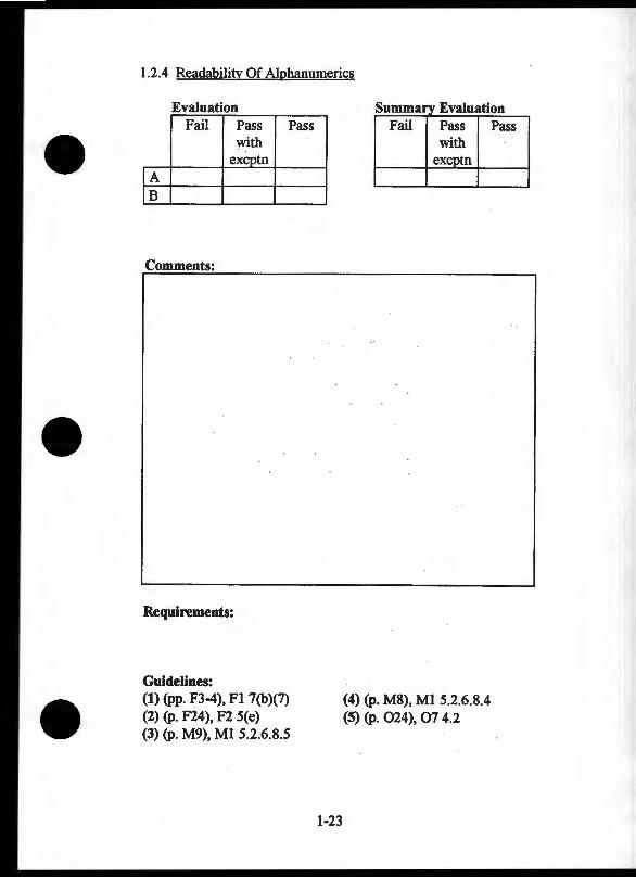
1.2.4 Readability Of Alphanumerics
Purpose: To evaluate the readability of display characters.
Test Procedure: View each screen or display. Read the display characters at a distance equal to the likely cockpit installation.
Evaluation Considerations: A) Character Identification (1, 2, 4, 5)
• Characters embedded in text • Upper and lower case (3)
B) Coding • Small symbol discriminability • Small alphanumeric discriminability
1-22
1.2.4 Readability Of Alphanumerics
Evaluation Fail Pass Pass
with exeptn
lA IB
Comments:
Requirements:
Guidelines: (1) (pp. F3-4), Fl 7(b)(7) (2) (p. F24), F2 5(e) (3) (p. M9), Ml 5.2.6.8.5
1-23
:summa Evaluation Fail Pass
with
(4) (p. M8), Ml 5.2.6.8.4 (S) (p. 024), 07 4.2
Pass
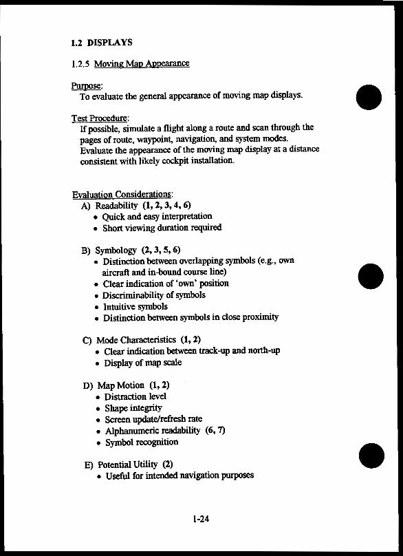
1.2 DISPLAYS
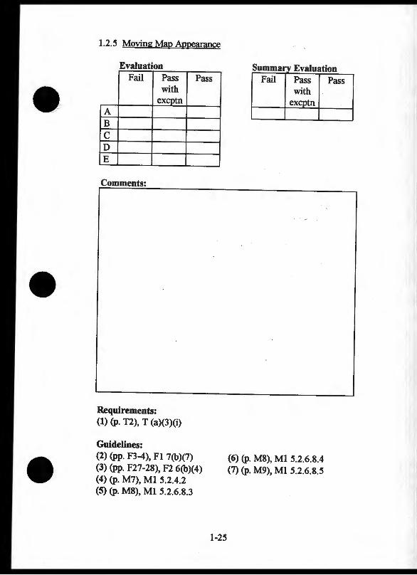
1.2.5 Moving Map Appearance
Purpose: To evaluate the general appearance of moving map displays.
Test Procedure: If possible, simulate a flight along a route and scan through the pages of route, waypoint, navigation, and system modes. Evaluate the appearance of the moving map display at a distance consistent with likely cockpit installation.
Evaluation Considerations: A) Readability (1, 2, 3, 4, 6)
• Quick and easy interpretation • Short viewing duration required
B) Symbology (2, 3, 5, 6) • Distinction between overlapping symbols (e.g., own
aircraft and in-bound course line) • Clear indication of 'own' position • Discriminability of symbols • Intuitive symbols • Distinction between symbols in close proximity
C) Mode Characteristics (1, 2) • Clear indication between track-up and north-up • Display of map scale
D) Map Motion (1, 2) • Distraction level • Shape integrity • Screen update/refresh rate • Alphanumeric readability (6, 7) • Symbol recognition
E) Potential Utility (2) • Useful for intended navigation purposes
1-24
1.2.5 Moving Map Appearance
Evaluation --
Fail Pass Pass with
ex:g>tn A B c D E
Comments:
Requirements: (1) (p. T2), T (a)(3)(i)
Guidelines: (2) (pp. F3-4), Fl 7(b)(7) (3) (pp. F27-28), F2 6(b)(4) (4) (p. M7), Ml 5.2.4.2 (5) (p. M8), Ml 5.2.6.8.3
1-25
Summa Evaluation Fail Pass
with ex tn
(6) (p. M8), Ml 5.2.6.8.4 (7) (p. M9), Ml 5.2.6.8.5
Pass
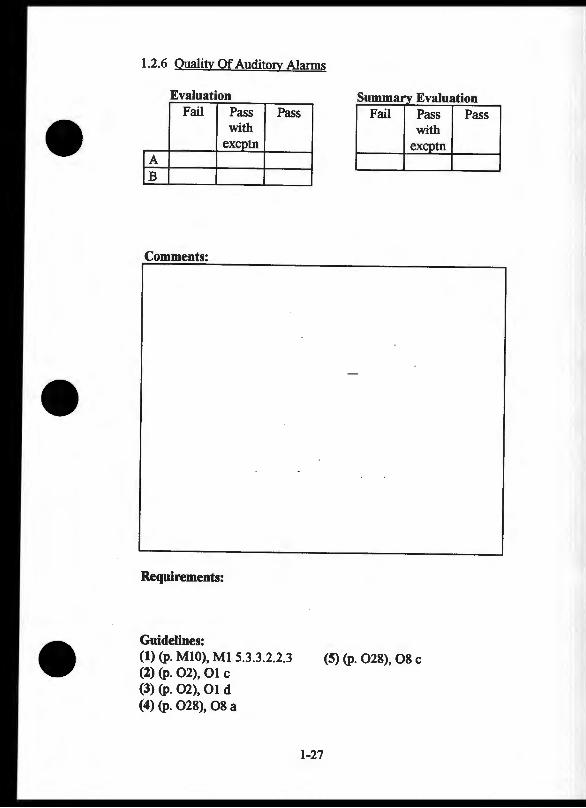
1.2 DISPLAYS
1.2.6 Quality Of Auditory Alarms
Purpose: To evaluate the quality of auditory alarms.
Test Procedure: Activate all possible auditory alarms. Pay attention to the quality of the alarms.
Evaluation Considerations: A) Audibility (5)
• Loudness • Pitch • Duration
B) Distraction Level (1, 2, 3, 4) • Loudness • Pitch • Duration
1-26
1.2.6 Quality Of Auditocy Alarms
Evaluation Fail Pass Pass
with excptn
[A [B
Comments:
Requirements:
Guidelines: (1) (p. MlO), Ml 5.3.3.2.2.3 (2) (p. 02), 01 c (3) (p. 02), 01 d (4) (p. 028), 08 a
1-27
s - Eval Fail Pass
with exg>tn
(5) (p. 028), 08 c
Pass
1.2 DISPLAYS
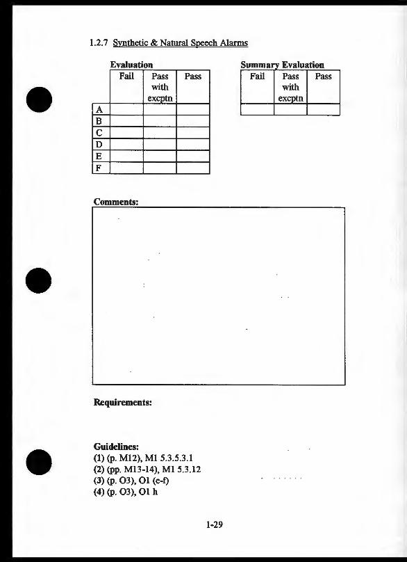
1.2. 7 Synthetic & Natural Speech Alarms
Purpose: To evaluate the quality of synthetic and natural speech displays.
Test Procedure: Activate all possible speech alarms. Pay attention to the quality of speech.
Evaluation Considerations: A) Audibility (1, 4)
B) Duration (1, 4) • Short duration • Non-distracting
C) Speech Rate (1, 4)
D) Accent/Dialect (1, 4)
E) Message Content Intelligibility (1, 2, 3, 4)
F) Ability to Distinguish from Controllers (1, 4)
1-28
1.2.7 Svnthetic & Natural Speech Alarms
Evaluation Fail Pass Pass
with excptn
A B c D E F
Comments:
Requirements:
Guidelines: (1) (p. M12), M1 5.3.5.3.1 (2) (pp. M13-14), M1 5.3.12 (3) (p. 03), 01 (e-f) (4) (p. 03), 01 h
Summary Evaluation Fail Pass Pass
with excptn
1-29
1.2 DISPLAYS
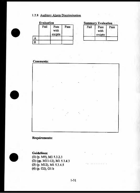
1.2.8 Auditory Alarm Discrimination
Purpose: To evaluate the ability to discriminate between alarms.
Test Procedure: Activate all possible auditory alarms. Pay attention to alarm discriminability.
Evaluation Considerations: A) Alarm Discriminability (1, 2, 3, 4)
• Pitch • Loudness • Type or pattern (e.g., steady tone vs. synthetic speech)
B) Discriminability Between Critical and Non-Critical Alarms (1, 2, 3) • Loudness • Pitch • Duration or pattern (several short tones vs. one long tone) • Message (e.g., "Critical-airspace violation" alert)
1-30
1.2.8 Auditozy Alann Discrimination
Evaluation Fail Pass Pass
with excptn
[A IB
Comments:
Requirements:
Guidelines: (1) (p. M9), M1 5.3.2.3 (2) (pp. Mll-12), Ml 5.3.4.3 (3) (p. M12), Ml 5.3.4.5 (4) (p. 02), 01 b
1-31
--~--- - .. ----·---Fail Pass
1.2 DISPLAYS
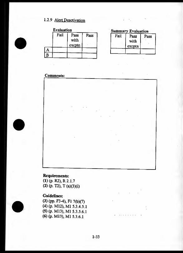
1.2.9 Alert Deactivation
Purpose: To evaluate the alert deactivation procedures.
Test Procedure: Activate and deactivate all possible alerts.
Evaluation Considerations: A) Pilot Controllability of Deactivation (1, 2, 5, 6)
• Alerts easily deactivated
B) Memory Requirements (1, 2, 3) • Alert status indicated redundantly (e.g., display text, light) • Additional warnings if problem not corrected when alert
has been deactivated (4, 5) • Low distraction caused by reoccurring alert ( 4, 5)
1-32
1.2.9 Alert Deactivation
Evaluation Fail Pass Pass
with excotn
rA (B
Comments:
Requirements: (1) (p. R2), R 2.1.7 (2) (p. T2), T (a)(3)(i)
Guidelines: (3) (pp. F3-4), F1 7(b)(7) (4) (p. M12), MI 5.3.4.5.1 (5) (p. Ml3), M1 5.3.5.6.1 (6) (p. M13), Ml 5.3.6.1
1-33
s Eval - ·-------Pass Pass with
ex tn
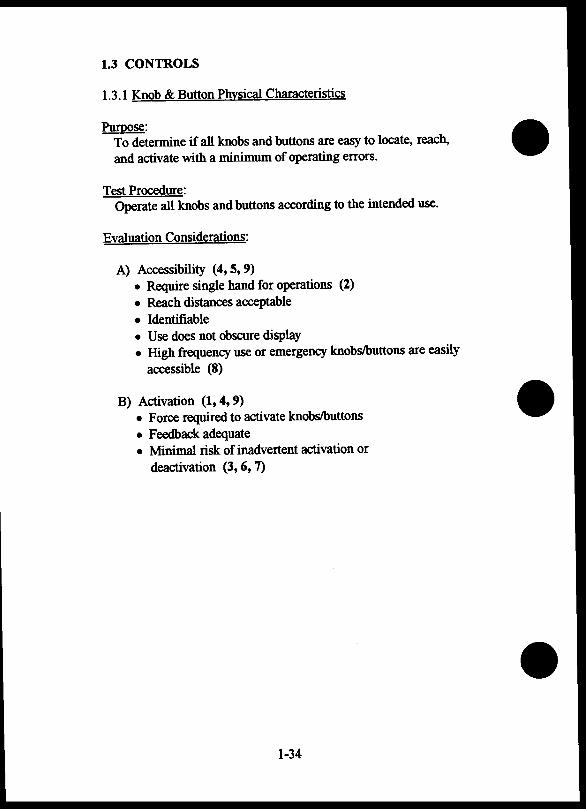
1.3 CONTROLS
1.3 .1 Knob & Button Physical Characteristics
Purpose: To determine if all knobs and buttons are easy to locate, reach, and activate with a minimum of operating errors.
Test Procedure: Operate all knobs and buttons according to the intended use.
Evaluation Considerations:
A) Accessibility (4, 5, 9) • Require single hand for operations (2) • Reach distances acceptable • Identifiable • Use does not obscure display • High frequency use or emergency knobs/buttons are easily
accessible (8)
B) Activation (1, 4, 9) • Force required to activate knobs/buttons • Feedback adequate • Minimal risk of inadvertent activation or
deactivation (3, 6, 7)
1-34
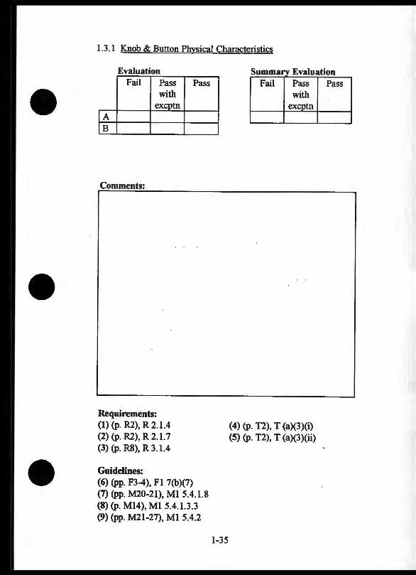
1.3 .1 Knob & Button Physical Characteristics
Evaluation Fail Pass
with exeptn
lA IB
Comments:
Requirements: (1) (p. R2), R 2.1.4 (2) (p. R2), R 2.1. 7 (3) (p. R8), R 3.1.4
Guidelines: (6) (pp. F3-4), Fl 7(b)(7)
Pass
(7) (pp. M20-21), Ml 5.4.1.8 (8) (p. Ml4), Ml 5.4.1.3.3 (9) (pp. M21-27), Ml 5.4.2
1-35
Summarv Evaluation Fail Pass
with exeptn
(4) (p. T2), T (a)(3)(i) (5) (p. T2), T (a)(3)(ii)
Pass
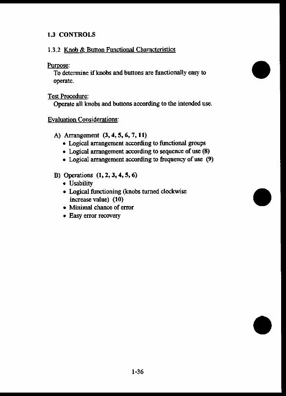
1.3 CONTROLS
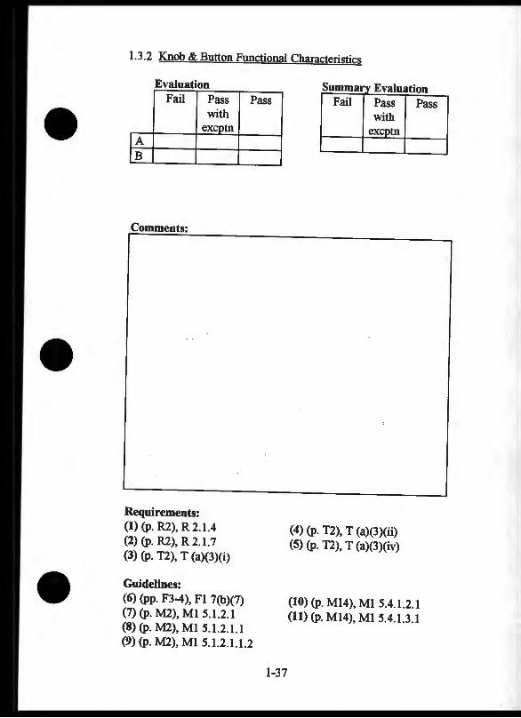
1.3.2 Knob & Button Functional Characteristics
Purpose: To determine if knobs and buttons are functionally easy to operate.
Test Procedure: Operate all knobs and buttons according to the intended use.
Evaluation Considerations:
A) Arrangement (3, 4, 5, 6, 7, 11) • Logical arrangement according to functional groups • Logical arrangement according to sequence of use (8) • Logical arrangement according to frequency of use (9)
B) Operations (1, 2, 3, 4, 5, 6) • Usability • Logical functioning (knobs turned clockwise
increase value) (10) • Minimal chance of error • Easy error recovery
1-36
1.3.2 Knob & Button Functional Characteristics
Evaluation Fail Pass Pass
with
rA excptn
[B
Comments:
Requirements: (1) (p. R2), R 2.1.4 (2) (p. R2), R 2.1. 7 (3) (p. T2), T (a)(3)(i)
Guidelines: (6) (pp. F3-4), Fl 7{b)(7) (7) (p. M2), Ml 5.1.2.1 (8) (p. M2), Ml 5.1.2.1.1 (9) (p. M2), Ml 5.1.2.1.1 .2
l-37
s _umma Eval --------- -Fail Pass
with ex tn
(4) (p. T2), T {a)(3)(ii) {5) (p. T2), T (a){3)(iv)
Pass I
(10) (p. M14), M1 5.4.1.2.1 (11) (p. M14), M1 5.4.1.3.1
1.3 CONTROLS
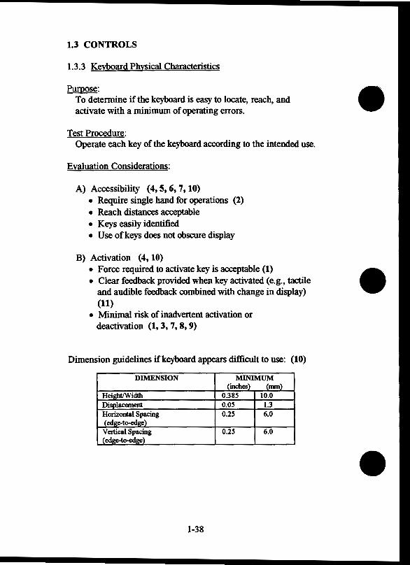
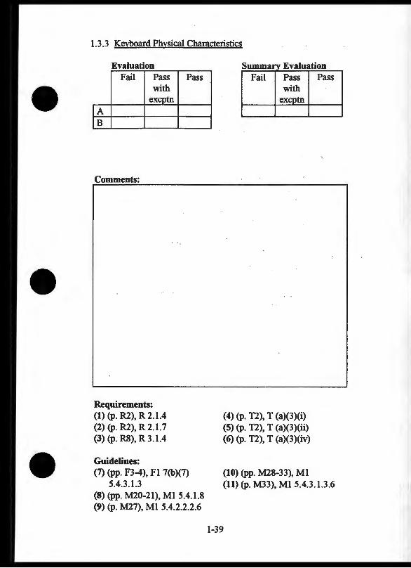
1.3.3 Keyboard Physical Characteristics
Purpose: To determine if the keyboard is easy to locate, reach, and activate with a minimum of operating errors.
Test Procedure: Operate each key of the keyboard according to the intended use.
Evaluation Considerations:
A) Accessibility (4, 5, 6, 7, 10) • Require single hand for operations (2) • Reach distances acceptable • Keys easily identified • Use of keys does not obscure display
B) Activation (4, 10) • Force required to activate key is acceptable (1) • Clear feedback provided when key activated (e.g., tactile
and audible feedback combined with change in display) (11)
• Minimal risk of inadvertent activation or deactivation (1,3,7,8,9)
Dimension guidelines if keyboard appears difficult to use: (10)
DIMENSION MINIMUM (inches) (nunl
Height/Width 0.38S 10.0 Displacement o.os 1.3 Horizontal Spacing 0.2S 6.0 ( edge-to-edie) Vertical Spacing 0.2S 6.0 (edge-to-edge)
-- -
1-38
1.3.3 Keyboard Physical Characteristics
Evaluation Fail Pass
with excptn
lA IB
Comments:
Requirements: (1) (p. R2), R 2.1.4 (2) (p. R2), R 2.1. 7 (3) (p. R8), R 3.1.4
Guidelines:
Pass
(7) (pp. F3-4), Fl 7(b)(7) 5.4.3.1.3
(8) (pp. M20-21), Ml 5.4.1.8 (9) (p. M27), Ml 5.4.2.2.2.6
Summaf Evaluation I Fail Pass I Pass
with exg>tn
(4) (p. T2), T (a)(3)(i) (5) (p. T2), T (a)(3)(ii) (6) (p. T2), T (a)(3)(iv)
(10) (pp. M28-33), Ml (11) (p. M33), Ml 5.4.3.1.3.6
l-39

1.3 CONTROLS
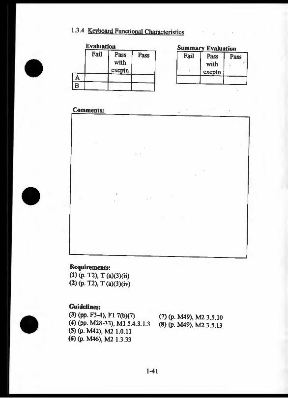
1.3.4 Keyboard Functional Characteristics
Purpose: To determine if keyboards are functionally easy to operate.
Test Procedure: Operate keyboard according to the intended use.
Evaluation Considerations:
A) Arrangement ( 4, 5, 6, 7) • Numeric keys arranged in a 3 x 3 + 1 matrix with zero
digit centered on bottom row • Alphabetic keys arranged in groups of 3 superimposed on
numeric keys in telephone keypad layout (e.g., 2 +ABC, 3 + DEF, etc.)
B) Operations (4, 6) • Key-press enters letter or character associated with label on
key • Clear, Backup, or Delete key to correct or reverse keyed
input (8, 9, 10, 11)
1-40
1.3 .4 Keyboard Functional Characteristics
Evaluation Fail Pass
with excptn
!A fB
Comments:
Requirements: (1) (p. T2), T {a)(3)(ii) (2) (p. T2), T (a)(3)(iv)
Guidelines: (3) (pp. F3-4), F1 7(b)(7)
Pass
(4) (pp. M28-33), M1 5.4.3.1.3 (5) (p. M42), M2 1.0.11 (6) (p. M46), M2 1.3.33
1-41
s Eval - ----_ _, - . - ------Fail Pass
with e~cptn
(7) (p. M49), M2 3.5.10 (8) (p. M49), M2 3.5.13
Pass

1.3 CONTROLS
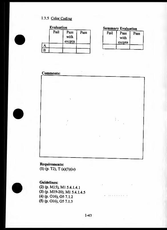
1.3.5 Color Coding
Purpose: To determine if color coding is designed to support usability.
Test Procedure: Examine the colors used to code all controls.
Evaluation Considerations:
A) General Use (1, 3, 4) • Colors used only when necessary to distinguish controls
(2) • Redundant coding of critical information (4)
B) Color Use (1, J, 4) • Colors discriminable under full range of cockpit lighting
conditions • Minimize the number of colors used (5) • Application should follow established conventions (e.g.,
RED for critical, emergency-specific controls)
1-42
1.3.5 Color Coding
Evaluation Fail Pass Pass
with excptn
lA IB
Comments:
Requirements: (1) (p. T2), T (a)(3)(iv)
Guidelines: (2) (p. M15), M1 5.4.1.4.1 (3) (p. M19-20), M1 5A.l.4.5 (4) (p. 016), 05 7.1.2 (5) (p. 016), 05 7.1.3
-
1-43
s _umma Evaluation Fail Pass Pass
with ex tn
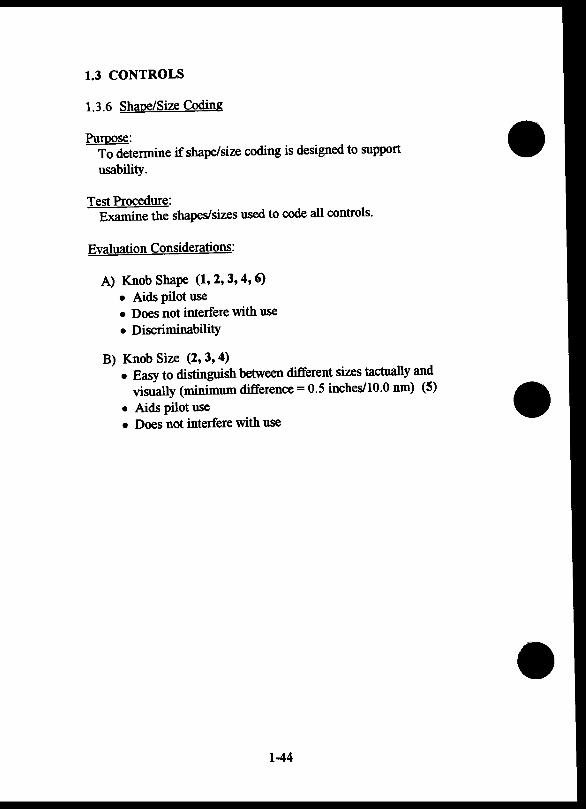
1.3 CONTROLS
1.3.6 Shape/Size Coding
Purpose: To determine if shape/size coding is designed to support
usability.
Test Procedure: Examine the shapes/sizes used to code all controls.
Evaluation Considerations:
A) Knob Shape (1, 2, 3, 4, 6) • Aids pilot use • Does not interfere with use • Discriminability
B) Knob Size (2, 3, 4) • Easy to distinguish between different sizes tactually and
visually (minimum difference= 0.5 inches/10.0 nm) (5)
• Aids pilot use • Does not interfere with use
1-44

1.3.6 Shape/Size Coding
Evaluation Fail Pass
with .
lA excptn
fB
Comments:
Requirements: (1) (p. R2), R 2.1.4 (2) (p. T2), T (a)(3)(iv)
Guidelines: (3) (pp. F3-4), Fl 7(b)(7) (4) (p. MIS), Ml S.4.1.4.1 (5) (p. MIS), MI S.4.1.4.3 (6) (p. MIS), MI S.4.1.4.4
Pass
l-4S
s E ummarv . _,.._...,._ Fail Pass Pass
with excptn I
I
1.3 CONTROLS
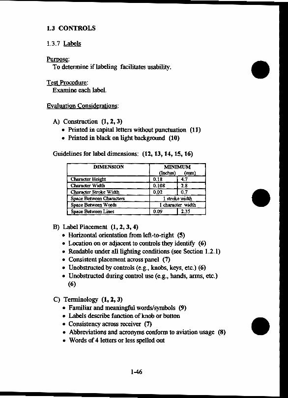
1.3.7 Labels
Purpose: To determine if labeling facilitates usability.
Test Procedure: Examine each label.
Evaluation Considerations:
A) Construction (1, 2, 3) • Printed in capital letters without punctuation (11) • Printed in black on light background (10)
Guidelines for label dimensions: (12, 13, 14, 15, 16)
DIMENSION MINIMUM (Inches) (mm)
Character Height 0.18 4.7 Character Width 0.108 2.8 Character Stroke Width 0.02 0.7 Space Between Characters 1 stroke width Space Between Words 1 character width Space Between Lines 0.09 I 2.35
B) Label Placement (1, 2, 3, 4) • Horizontal orientation from left-to-right (5) • Location on or adjacent to controls they identify (6) • Readable under all lighting conditions (see Section 1.2.1) • Consistent placement across panel (7) • Unobstructed by controls (e.g., knobs, keys, etc.) (6) • Unobstructed during control use (e.g., hands, arms, etc.)
(6)
C) Terminology (1, 2, 3) • Familiar and meaningful words/symbols (9) • Labels describe function of knob or button • Consistency across receiver (7) • Abbreviations and acronyms conform to aviation usage (8) • Words of 4 letters or less spelled out
1-46
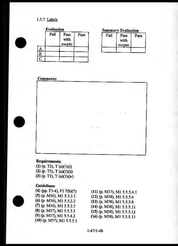
1.3. 7 Labels
Evaluation -- - - - ~
Fail Pass with
excptn A B c
Comments:
Requirements: (1) (p. T2), T (a)(3)(i) (2) (p. T2), T (a)(3)(ii) (3) (p. T2), T (a)(3)(iv)
Guidelines: (4) (pp. F3-4), F1 7(b)(7) (5) (p. M36), M1 5.5.2.1 (6) (p. M36), M1 5.5.2.2 (7) (p. M36), M1 5.5.2.3 (8) (p. M37), M1 5.5.3.2 (9) (p. M37), M1 5.5.4.2 (10) (p. M37), M1 5.5.5.1
Pass
I
Summaf Evaluation I Fail Pass I Pass
with excptn
(11) (p. M37), M1 5.5.5.4.1 (12) (p. M38), M1 5.5.5.6 (13) (p. M38), Ml 5.5.5.8 (14) (p. M38), Ml 5.5.5.11 (15) (p. M38), M1 5.5.5.12 (16) (p. M38), M1 5.5.5.13
1-47/1-48

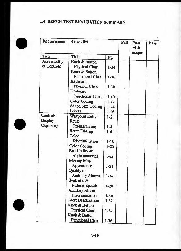
1.4 BENCH TEST EVALUATION SUMMARY
Requirement Checklist Fail Pass Pass with excptn
Title Title P2. Accessibility Knob & Button of Controls Physical Char. 1-34 1
Knob & Button Functional Char . . 1-36
Keyboard Physical Char. 1-38
Keybo~d Functional Char. 1-40
Color Coding 1-42 Shape/Size Coding 1-44 Labels 1-46
ControV Waypoint Entry 1-2 Display Route Capability Programming 1-4
Route Editing 1-6 Color
Discrimination 1-18 Color Coding 1-20 Readability of
Alphanumerics 1-22 Moving Map
Appearance 1-24 Quality of
Auditory Alarms 1-26 Synthetic &
Natural Speech 1-28 Auditory Alarm
Discrimination 1-30 Alert Deactivation 1-32 Knob & Button
Physical Char. 1-34 Knob & Button
Functional Char. 1-36
1-49
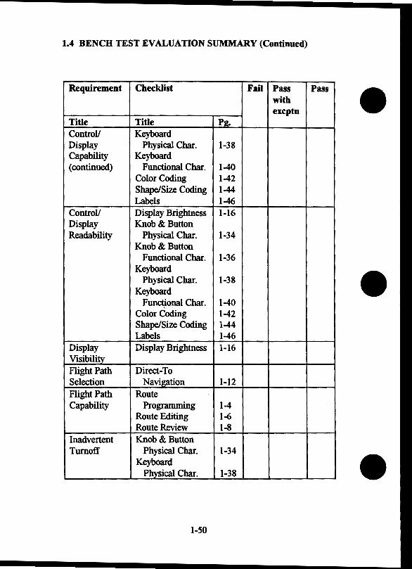
1.4 BENCH TEST EVALUATION SUMMARY (Continued)
Requirement Checklist Fail Pass Pass with excptn
Title Title Pg. ControV Keyboard Display Physical Char. 1-38 Capability Keyboard (continued) Functional Char. 1-40
Color Coding 1-42 Shape/Size Coding 1-44 Labels 1-46
ControV Display Brightness 1-16 Display Knob & Button Readability Physical Char. 1-34
Knob & Button Functional Char. 1-36
Keyboard Physical Char. 1-38
Keyboard Fun~onal Char. 1-40
Color Coding 1-42 Shape/Size Coding 1-44 Labels 1-46
Display Display Brightness 1-16 Visibility Flight Path Direct-To Selection Navigation 1-12 Flight Path Route Capability Programming 1-4
Route Editing 1-6 Route Review 1-8
Inadvertent Knob & Button Turnoff Physical Char. 1-34
Keyboard Physical Char. 1-38
1-50

1.4 BENCH TEST EVALUATION SUMMARY (Continued)
Requirement Checklist Fail Pass Pass with excptn
Title Title Pg. Operation of Route Reversal 1-10 Controls Nearest Waypoint 1-14
Color Discrimination 1-18
Color Coding 1-20 Readability of
Alphanumerics 1-22 Moving Map
Appearance 1-24 Quality of
Auditory Alanns 1-26 Synthetic &
Natural Speech 1-28 Auditory Alarm
Discrimination 1-30 Alert Deactivation 1-32 Knob & Button
Physical Char. 1-34 Knob & Button
Functional Char. 1-36 Keyboard
Physical Char. 1-38 Keyboard
Functional Char. 1-40 Labels 1-46
Waypoint Waypoint Entry 1-2 Entry
Waypoint Route Review 1-8 or Direct-To Leg Navigation 1-12 Sequencing Color
Discrimination 1-18 Waypoint Route Storage Pro 1-4
1-51
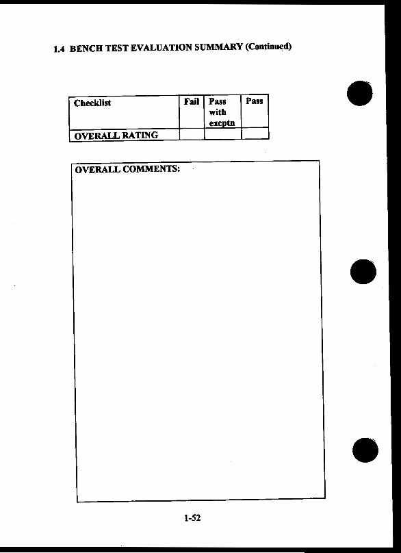
1.4 BENCH TEST EVALUATION SUMMARY (Continued)
Checklist Fail Pass Pass with excptn
OVERALL RATING
OVERALL COMMENTS:
1-52


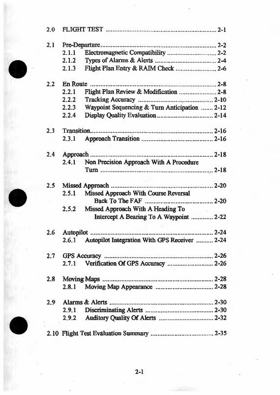
2.0 FLIGIIT TEST ............... ... ........... ............ ...... ........... .. ..... 2-1
2.1 Pre-Departure ........ ............. ........ ......... .. ........ ..... .. ... .... ..... .. 2-2 2.1.1 Electromagnetic Compatibility ..... .... ...... .............. 2-2 2.1.2 Types of Alarms & Alerts .... ........... ....... ...... .. ... ... 2-4 2.1.3 Flight Plan Entry & RAIM Check .... ...... ....... .. ..... 2-6
2.2 En Route ..... ......... .. .......... ... .. ............ ......................... ...... 2-8 2.2.1 Flight Plan Review & Modification ............. .... .. .. . 2-8 2.2.2 Tracking Accuracy ..... ... ... .... ....... : ... .......... .. ..... . 2-10 · 2.2.3 Waypoint Sequencing & Tum Anticipation .. ..... 2-12 2.2.4 Display Quality Evaluation ......................... .. ..... . 2-14
2.3 Transition .. .. .. .... ..... ... ...... .. .. ........... ... ...... ........ ... ..... .. ...... 2-16 2.3.1 Approach Transition ......... ............... .................. 2-16
2.4 Approach ..... .. ............. .. ................... ............................... 2-18 2.4.1 Non Precision Approach With A Procedure
Tum ........................ .. ..... .. .. ..... .. .. ... .... ....... .. .. .... 2-18
2.5 Missed Approach .... .. ...................................................... 2-20 2.5.1 Missed Approach With Course Reversal
Back To The F AF ..... ........... .. .................. .... 2-20 2.5.2 Missed Approach With A Heading To
Intercept A Bearing To A Waypoint ............. 2-22
2.6 Autopilot .. ...... .. ....... .. ....... .. .......... .................................. 2-24 2.6.1 Autopilot Integration With GPS Receiver .......... 2-24
2. 7 GPS Accuracy ....................... .... ............ .. ..................... .. 2-26 2.7.1 Verification OfGPS Accuracy ........................... 2-26
2.8 MovingMaps .... ........................... .................................. 2-28 2.8.1 Moving Map Appearance ........ .. ................ ........ 2-28
2.9 Alarms & Alerts ............. .. .............................................. 2-30 2.9.1 Discriminating Alerts .... : ................. .... .. ............ 2-30 2.9.2 Auditory Quality Of Alerts ..... .. ... ....... .. ............. 2-32
2.10 Flight Test Evaluation Summary ..................................... 2-35
2-1
2.1 PRE-DEPARTURE
2.2.1 Electromagnetic Compatibility
Purpose: Determine use of selective radio frequencies on GPS operations.
Note: Reevaluation of installed VHF transceiver performance is not necessary if the filter insertion loss is 2 dB or less.
Test Procedure: Fly direct to a waypoint:
1. While en route, tune each of the following frequencies for at least 20 seconds & activate mike repeatedly (Note: coordinate with ATC if local frequencies) (1):
121.125 Mhz 131.200 MHz 121.150 MHz 131.225 MHz 121.175 MHz 131.250 MHz 121.200 MHz 131.275 MHz 121.225 MHz 131.300 MHz 121.250 Mhz 131.325 MHz
131.350 MHz
Evaluation Considerations: A) Influence on: (2, 3)
CDI indication Display quality Digital cross track error Distance to waypoint Alerts and warnings
B) Influence on satellite HOOP value Sat (2, 3)
2-2
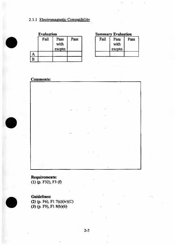
2 .1 .1 Electromagnetic Compatibility
Evaluation Fail Pass
with ex_g>tn
lA IB
Comments:
Requirements: (1) (p. F32), F3 (f)
Guidelines:
Pass
(2) (p. F6), F1 7(c)(iv)(C) (3) (p. F9), F1 8(b)(6)
Summa_ry Evaluation Fail Pass Pass
with excptn
2.1 PRE-DEPARTURE
2.1.2 Types Of Alanns & Alerts
Purpose: To ensure that alarms & alerts activate appropriately. (1)
Evaluation Considerations: Each of the following alanns & alerts shall be "timely" (shall take place within the specified time to alarm for the phase of flight in progress) and shall be as follows:
A) A navigation warning flag shall be displayed on the navigation display in the following cases: (2, 3) • The absence of power required for the navigation function • Loss of navigation function • Inadequate or invalid navigation data in the approach
mode detected in accordance with RTCA- DO- 208 • The loss of the RAIM detection function in the approach
mode at the final approach fix. • Loss of the RAIM detection function in the approach
mode, after passing the final approach fix. (Only if the RAIM detection function is lost for more than 5 minutes.)
B) RAIM alerts (1, 2, 3) • When RAIM is not available, inadequate navigation data
due to poor space vehicle geometry such that the probability that navigation error exceeds the position integrity performance requirements in RTCA/D0-208 is greater than or equal to 0.5
• The RAIM function detects a position error that exceeds the GPS position integrity performance requirements in RTCA/D0-208
• Loss of the RAIM function • Predicted unavailability of the RAIM detection function • When operating in the approach mode without RAIM and
navigation performance is degraded because HDOP exceeds 4.0
2-4
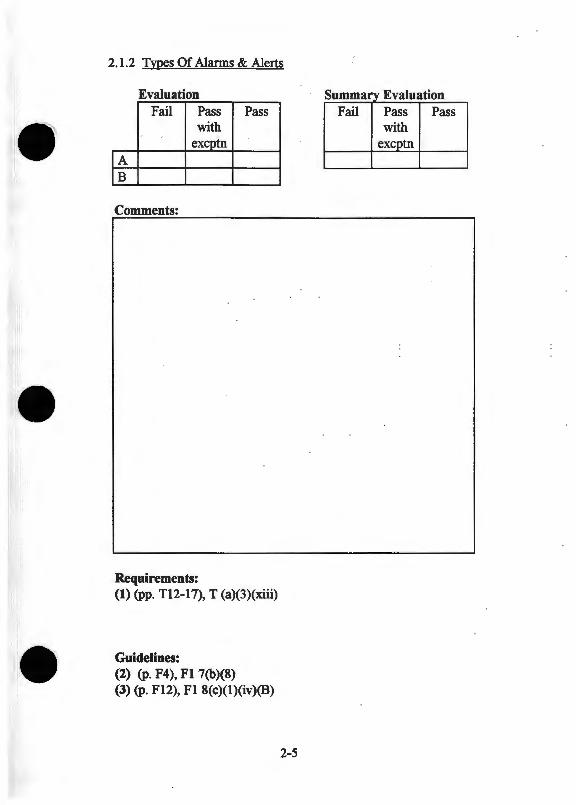
2.1.2 Tvoes Of Alarms & Alerts
Evaluation s Eal ummary v uat10n Fail Pass Pass Fail Pass Pass
with with exeptn excptn
fA fB
Comments:
Requirements: (1) (pp. Tl2-17), T (a)(3)(xiii)
Guidelines: (2) (p. F4), Fl 7(b)(8) (3) (p. F12), Fl 8(c)(l)(iv)(B)
2-5
2.1 PRE-DEPARTURE
2.1.3 Flight Plan Entry & RAIM Check
Purpose: To evaluate procedures required for flight plan entry & RAIM check.
Test Procedure: While on ground:
1. Enter a 9 waypoint flight plan ( 4, 6, 8) 2. Conduct RAIM check for ETA (5)
Evaluation Considerations: A) Control easy to access and identify (7)
• Reach distance • Identification of controls and control operation • Visibility of displays when using controls
B) Control use sequence requires minimal reliance on memory & promotes error free operation (1, 2, 3, 6, 7) • Number and combination of controls used • Number of control actions required • Probability of data entry errors • Ease of error detection • Ease of error recovery • Pilot knowledge of what to do next
C) Display output (6, 7) • Readability with acceptable change in body position (3) • Messages understandable
2-6
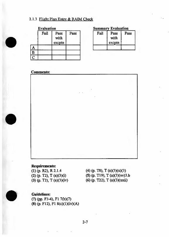
2.1.3 Flight Plan Entry & RAIM Check
Evaluation Fail Pass
with excptn
A B
c
Comments:
Requirements: (1) (p. R2), R 2.1.4 (2) (p. T2), T (a)(3)(i) (3) (p. T2), T (a)(3)(iv)
Guidelines:
Pass
(7) (pp. F3-4), Fl 7(b)(7) (8) (p. F12), F l 8(c)(l)(iv)(A)
s ummary Eal v uatlon Fail Pass Pass
with excptn
(4) (p. T8), T (a)(3)(x)(3) (5) (p. T19), T (a)(3)(xv)3.b (6) (p. T22), T (a)(3)(xxii)
2-7
2.2 ENROUTE
2.2.1 Flight Plan Review & Modification
Purpose: Evaluate ease of reviewing and modifying a flight plan while in flight.
Test Procedure: Fly several consecutive legs in the flight plan. While flying to a waypoint in the flight plan:
1. Review legs or segments of the flight plan (8) 2. Obtain distance, bearing & name of the active waypoint (8) 3. Change two consecutive intermediate waypoints (8)
Evaluation Considerations: A) Operation of waypoint sequencing ( 6)
B) Accessibility of flight critical information
C) Display readability ( 4, 5, 7)
D) Ease oflocating waypoints in database (1, 2, 4, 7)
E) Clarity of waypoint categories
W) Workload: (7) • Adequate situational awareness • Minimal mental effort • Minimal number of control actions
2-8
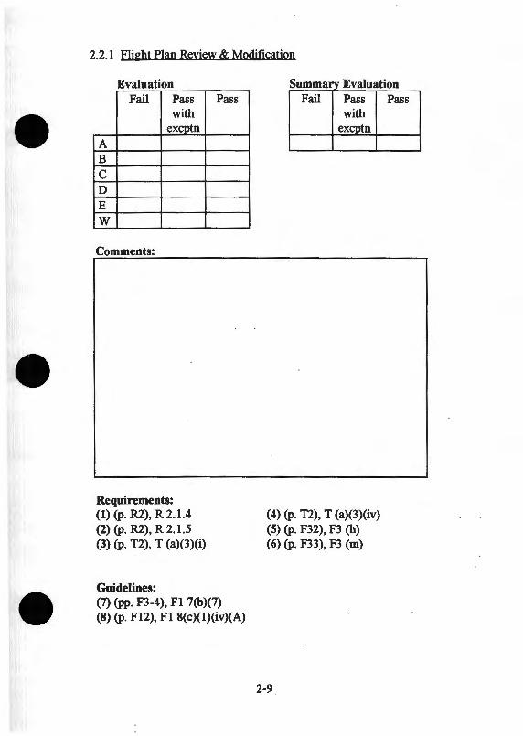
2.2.1 Flight Plan Review & Modification
Evaluation Fail Pass
with excptn
A B c D E w
Comments:
Requirements: (1) {p. R2), R 2.1.4 (2) {p. R2), R 2.1.5 (3) {p. T2), T (a)(3)(i)
Guidelines:
Pass
(7) {pp. F3-4), F1 7(b)(7) (8) {p. F12), F1 8(c)(l)(iv)(A)
s Eal ummary v uat10n Fail Pass
with excptn
(4) {p. T2), T (a)(3)(iv) (5) {p. F32), F3 (h) (6) {p. F33), F3 (m)
2-9
Pass
2.2 ENROUTE
2.2.2 Tracking Accuracy
Purpose: To evaluate ease of course intercept and tracking accuracy (with and without autopilot).
Test Procedure: Perfonn the following both with and without the autopilot:
1. Intercept a segment & fly to a waypoint in flight plan (4)
Evaluation Considerations: A) Utility of track angle error information and CDI for course
intercept (2)
B) Effort required to maintain FTE at less than 1.0 run (5)
C) Ability to intercept route segment (6)
D) Ability to adjust CDI sensitivity in flight (3)
2-10
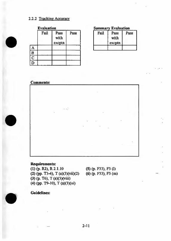
2.2.2 Tracking Accuracy
Evaluation Fail Pass Pass
with excptn
A B c D
Comments:
Requirements: (1) (p. R2}, R 2.1.10 (2) (pp. T3-4), T (a)(3)(vii)(2) (3) (p. T6}, T (a)(3)(viii) (4) (pp. T9-10), T (a)(3)(xi)
Guidelines:
Summary Evaluation Fail Pass Pass
with excptn
(5) (p. F33), F3 (l) (6) (p. F33), F3 (m)
2-11
2.2 ENROUTE
2.2.3 Waypoint Sequencing & Tum Anticipation
Purpose: To evaluate waypoint sequencing procedure, associated display indications, and tum anticipation.
Test Procedure: While in flight plan mode, fly to a waypoint and:
• Fly to the left and right of a "fly by" waypoint at the intersection of two flight plan segments defining a 900 tum. (7) This will require the following passes by the "corner'' waypoint: • Fly a course parallel with the approaching en route
segment with the CDI nearly pegged to the outside (left of course) and follow tum anticipation advisory
• Repeat with CDI nearly pegged to the inside (right of course)
• Repeat with CDI on center line • Repeat with CDI on center line using autopilot
Evaluation Considerations A) Waypoint alert visibility (7)
B) Tum anticipation facilitates smooth transition to next segment using not more than a standard rate tum (1, 6)
C) Information provided to pilot by CDI and message display not misleading (4)
D) Waypoint sequencing consistent and facilitates accurate tracking of airway (2, 3, 6, 7)
E) Verify full scale deflection of CDI +/- 5.0 nm (3)
F) Verify resolution of crosstrack error at least 0.10 nm (3)
2-12
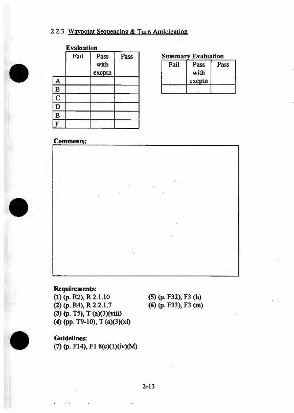
2.2.3 Waypoint Sequencing & Turn Anticipation
Evaluation Fail Pass
with excptn
A B c D E F
Comments:
Requirements: (1) (p. R2), R 2.1.1 0 (2) (p. R4), R2.2.1.7
Pass
(3) (p. T5), T (a)(3)(viii) (4) (pp. T9-10), T (a)(3)(xi)
Guidelines: (7) (p. F14), Fl 8(c)(l)(iv)(M)
Summary EvaluatiOn Fail Pass Pass
with excptn
(5) (p. F32), F3 (h) (6) (p. F33), F3 (m)
2-13
2.2 ENROUTE
2.2.4 Display Quality Evaluation
Purpose: Evaluate influences of sunlight on display readability.
Test Procedure: Exit flight plan & fly direct to waypoints which will position the aircraft in each of the following orientations: (3, 6)
• Directly into the sun • With the sunlight shining across the display from a side
window
Evaluation Considerations: A) Readability of symbols, letters, numbers, and graphics (7)
B) Visibility of CDI display (6, 7)
C) Range of brightness adjustment (2, 7) • Manual adjustment • Automatic adjustment
D) Display location (1)
E) Visibility of alerts & warnings ( 4, 5)
F) Color discriminability
2-14
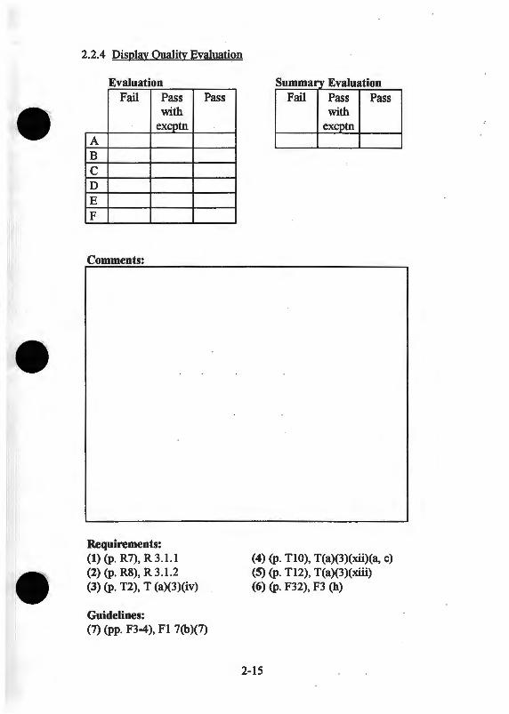
2.2.4 Display Quality Evaluation
Evaluation Fail Pass
with excptn
A B c D E F
Comments:
Requirements: (1) (p. R7), R 3.1.1 (2) (p. R8), R 3.1.2 (3) (p. T2), T (a)(3)(iv)
Guidelines:
Pass
(7) (pp. F3-4), Fl 7(b)(7)
s Eal ummary v uat10n Fail Pass Pass
with excptn
(4) (p. TIO), T(a)(3)(xii)(a, c) (5) (p. T12), T(a)(3)(xiii) (6) (p. F32), F3 (h)
2-15
2.3 TRANSITION
2.3.1 Approach Transition
Purpose: To evaluate receiver functions involved in transition from en route to approach mode.
Test Procedure: 1. Approach terminal area while in flight plan mode, from
beyond 30 miles from the airport 2. Select an IAF for an appropriate procedure which includes a
course reversal & fly to the IAF During this procedure: (2)
• Observe terminal area alert • Enable approach mode • Request RAIM check (6)
Evaluation Considerations: A) Clarity ofiAF options (1)
B) Ability to select one IAF option (1)
C) Action required to select approach mode (2, 4)
D) Smoothness of changes in CDI sensitivity (3)
E) Ease of understanding status of receiver mode (5)
F) Understandability of displayed messages
G) Approach enable alert • At a radial distance of 30 nm from the destination airport
(not distance along the flight plan route) (2, 5)
H) Barometric pressure alert (5, 7) • Informs the pilot of the need to manually insert the
barometric pressure setting (unless the automatic altitude input utilizes barometric corrected altitude data). (2)
2-16

2.3.1 Approach Transition
Evaluation s ummary EvaluatiOn Fail Pass Pass Fail Pass Pass
with with excptn excptn
A B c D E F G H
Comments:
Requirements: (1) (p. T8), T (a)(3)(x)b (5) (p. T17), T (a)(3)(xiii)4 (2) (p. TIO), T (a)(3)(xii)l.a (6) (p. T19), T (a)(3)(v)c (3) (pp. TI0-11), T (a)(3)(xii)l.b, 5.b (4) (p. Til), T (a)(3)(xii)l.c
Guidelines: (7) (p. Fll), F1 8(b)(10)
2-17
2.4 APPROACH
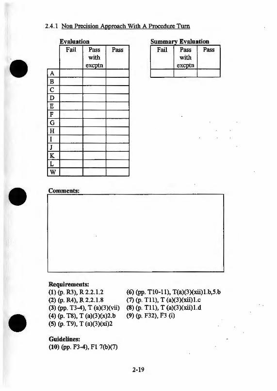
2.4.1 Non Precision Approach With A Procedure Turn
Purpose: To check receiver operations involved in transitioning from initial approach fix to final approach fix when a procedure turn is required.
Test Procedure: Fly from IAF, where IAF is on the airport or coincident with the F AF, fly the procedure turn, and fly inbound to the missed approach point.
Evaluation Considerations: A) Course guidance outbound & inbound (5) B) Message displays readable & understandable C) Receiver mode status indicator (7) D) Transitions between terminal & approach mode (8) E) Waypoint sequencing & timing of waypoint alerts (4) F) Procedures required to enable a course reversal procedure (5) G) Access to ground speed, distance, XTE, bearing & track
angle error information (1, 2, 3) H) CDI sensitivity changes smooth, and at appropriate
locations (6) I) Information on active waypoint (2) J) Operation consistent with pilot expectations K) Sensitivity change alert (7)
• At a distance of 3 nm inbound to the final approach fix an annunciation shall indicate that a change will occur in the sensitivity of the analog CDI.
L) Approach enable alert shall be repeated (7) • At 3nm from the F AF if the approach mode was not
previously activated. W) Workload: (9, 10)
• Pilot situational awareness • Mental effort • Number of control actions required
2-18
2.4.1 Non Precision Approach With A Procedure Turn
Evaluation Fail Pass
with excptn
A B c D E F G H I J K L w
Comments:
Requirements: (1) (p. R3), R2.2.1.2 (2) (p. R4), R 2.2.1.8
Pass
(3) (pp. T3-4), T (a)(3)(vii) (4) (p. T8), T (a)(3)(x)2.b (5) (p. T9), T (a)(3)(xi)2
Guidelines: (10) (pp. F3-4), F1 7(b)(7)
s E al f ummary v ua aon Fail Pass Pass
with excptn
(6) (pp. Tl0-11), T(a)(3)(xii)l.b,5.b (7) (p. Tl1), T (a)(3)(xii)l.c (8) (p. Tl1), T (a)(3)(xii)l.d (9) (p. F32), F3 (i)
2-19
2.5 MISSED APPROACH
2.5.1 Missed Approach With Course Reversal Back To The F AF
Purpose: Evaluate receiver function when missed approach requires a course reversal back to F AF using "DIRECT TO" function to enable course guidance to the hold point.
Test Procedure: (8) 1. Activate the "DIRECT TO" button while flying the runway
heading, reverse course and follow CDI guidance to the F AF 2. Fly the published hold at the F AF using the OBS function to
select inbound leg to the hold waypoint.
Evaluation Considerations: A) Receiver shift out of automatic waypoint sequencing at the
MAP (5)
B) Positive course guidance provided as an extension of the inbound track and distance from the MAP until manual selection of the next waypoint (5)
C) Actions required to return to the F AF (5)
D) OBS function use for the holding pattern (4)
E) Missed approach holding waypoint as "fly over'' waypoint (1, 2)
F) Course guidance to the F AF (2)
G) Sensitivity change for the missed approach (6)
W) Workload (7, 9) • Pilot situational awareness • Mental effort • Number of control actions required • Frequency of reference to receiver display required
2-20

2.5.1 Missed Approach With Course Reversal Back To The F AF
Evaluation Fail Pass Pass
with excptn
A B c D E F G w
Comments:
Requirements: (1) (p. T3), T (a)(3)(v) (2) (p. T8), T (a)(3)(x)b (3) (p. T9), T (a)(3)(x)(4) (4) (p. T9), T (a)(3)(xi)2.b
Guidelines: (9) (pp. F3-4), Fl 7(b)(7)
s Eal ummary v uatlon Fail Pass Pass
with excptn
(5) (p. TlO), T (a)(3)(xi)3 (6) (p. Tll), T (a)(3)(xii)5.b (7) (p. F32), F3 (i) (8) (p. F33), F3 (k)
2-21
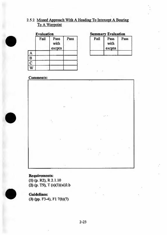
2.5 MISSED APPROACH
2.5.2 Missed Approach With A Heading To Intercept A Bearing To A Waypoint
Purpose: Evaluate receiver operation when intercepting a bearing to a holding point using the OBS function.
Test Procedure: 1. Fly the center line extension & select the bearing to the
waypoint using the OBS function. 2. Intercept the course and fly to the hold point.
Evaluation Considerations: A) Use of OBS function for course to hold waypoint (2)
B) The readability of the OBS setting (2)
C) Turn anticipation at point of intercept for course change to hold point (1)
W) Workload: (3) • Pilot situational awareness & mental effort • Number of control actions required • Required reference to receiver display
2-22
2.5.2 Missed Approach With A Heading To Intercept A Bearing To A Waypoint
Evaluation s umma_! Eal y v uation Fail Pass Pass Fail Pass Pass
with with excptn excptn
A B c w
Comments:
Requirements: (1) (p. R2), R 2.1.10 (2) (p. T9), T (a)(3)(xi)2.b
Guidelines: (3) (pp. F3-4), Fl 7(b)(7)
2-23
2.6 AUTOPILOT
2.6.1 Autopilot Integration With GPS Receiver
Purpose: To evaluate the function of the GPS receiver when used with an autopilot during en route, terminal, and approach operations.
Test Procedure: 1. Couple the GPS receiver to the autopilot (4) 2. Fly the following: (1, 5)
• Transition from en route to fly an approach • Fly a missed approach & hold
Evaluation Considerations: A) Course tracking smoothness & precision (2)
B) Performance: (1) • Direct to operations • Turn anticipation • Course reversals • Waypoint sequencing
C) Adequacy of information necessary for pilot situation awareness regarding system status & operation.
D) Operation consistent with pilot expectations
W) Workload (3) • Mental effort required • Number of control actions required • Required reference to receiver display
2-24

2.6.1 Autopilot Integration With GPS Receiver
Evaluation Fail Pass
with excptn
A B c D w
Comments:
Requirements: (1) (p. F32), F3 (c) (2) (p. F33), F3 (1)
Guidelines:
Pass
(3) (pp. F3-4), Fl 7(b)(7) (4) (p. F4), Fl 7(b)(9) (5) (p. F6), Fl 7(c)(l)(iv)(B)
s ummary E al f v ua tOn
Fail Pass Pass with
excptn
2-25

2. 7 GPS ACCURACY
2.7.1 Verification OfGPS Accuracy
Purpose: Verify the GPS accuracy over a surveyed position on the ground.
Test Procedure: 1. In the en route. tenninal. and approach modes: (1)
• Conduct at least 5 low altitude (<100ft AGL) passes of one or more surveyed locations (survey location data must be in either the WGS-84 or NAD-83 coordinate datum; e.g., waypoint at the runway threshold). (3)
• Push the "save position" button that will record Lat/Lon when the aircraft crosses the designated location and compare with known survey coordinates.
Evaluation Considerations: A) Recorded Lat/Lon measurements (1)
Box Mode: En Route Tenninal Approach Accuracy Required 0.124 nm 0.124nm 0.056nm Known Lat/Lon
Recorded Lat/Lon 1
2
3
4
5
2-26

2.7.1 Verification OfGPS Accuracy
Evaluation Fail Pass
with excptn
lA
Comments:
Requirements: (1) (p. F33), F3 (j)
Guidelines: (2) (p. F3), Fl 7(b)
Pass
(3) (p. F6), Fl 7(c)(l)(iv)(D)
2-27
Summary Evaluation Fail Pass Pass
with excptn
2.8 MOVING MAPS
2.8.1 Moving Map Appearance
Purpose: To evaluate the appearance of the moving map display in flight. Observe the appearance of the map in en route and approach modes during straight flight and during changes in heading and course.
Test Procedure: Examine the appearance of the moving map display during straight flight and heading changes.
Evaluation Considerations: A) Apparent readability of display (1)
B) Appearance of small symbols and fine lines during map movement (1, 2, 3, 4, 5, 6)
C) Clarity of location and heading of aircraft symbol on plan & profile views (1, 2, 4, 5)
D) Map scale appropriate and clear (1)
E) Map update rate appropriate for en route and terminal operations (1, 7)
2-28

2.8.1 Moving Map Appearance
Evaluation Fail Pass Pass
with excptn
A B c D E
Comments:
Requirements:
Guidelines: (1) (pp. F3-4), Fl 7(b)(7) (2) (p. F27), F2 6(b )( 4) (3) (p. M7), M1 5.2.4.2 (4) (p. M8), Ml 5.2.6.8.3
s Eal ummary v uatlon Fail Pass Pass
with excptn
(5) (p. M8), Ml 5.2.6.8.4 (6) (p. M9), Ml 5.2.6.8.5 (7) (p. 012), 04 5.2.1
2-29
2.9 ALARMS & ALERTS
2. 9.1 Discriminating Alerts
Purpose: To ensure that all alerts can be discriminated from each other and from background noise. (1)
Test Procedure: For each alert evaluate the following:
Evaluation Considerations: A) Ability of alert to get pilot's attention
B) Ease of discriminating alert from background
C) Ease of discriminating critical alerts from other alerts
D) Clarity of alert message
E) Alert contribution to "noisy" cockpit • Distraction
F) Effort to deactivate alert
G) Alert reminders if alert turned off and situation not reconciled
2-30
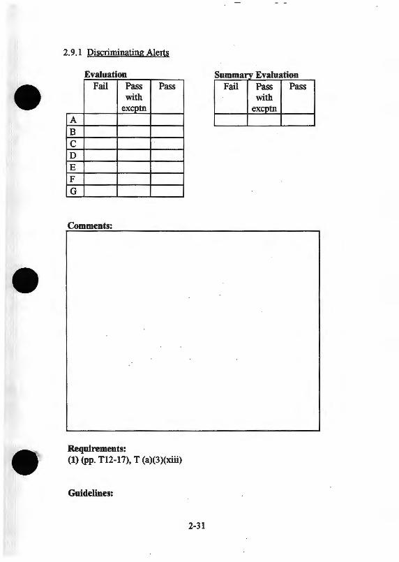
2. 9.1 Discriminating Alerts
Evaluation Summarv Evaluation Fail Pass Pass Fail Pass Pass
with with excptn excptn
A B c D E F G
Comments:
Requirements: (1) (pp. T12-17), T (a)(3)(xiii)
Guidelines:
2-31
2.9 ALARMS & ALERTS
2.9.2 Auditory Quality Of Alerts
Purpose: To ensure that auditory alarms are appropriate. (1)
Test Procedure: For each alarm & alert evaluate the following:
Evaluation Considerations: A) Clarity of alarm
• Loudness • Pitch • Duration
B) Synthetic or natural speech quality & intelligibility in te~ of: • Speech rate • Accent/dialect • Gender • Distinguishable from controllers
C) Length of auditory alarm • Minimal distraction • Minimal amount of attention to extract message
2-32
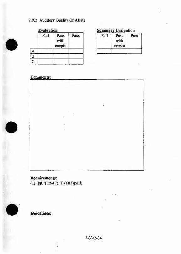
2.9.2 Auditory Quality Of Alerts
Evaluation s Eal ummary v uat10n Fail Pass Pass Fail Pass Pass
with with excptn excptn
A B c
Comments:
Requirements: (1) (pp. T12-17), T (a)(3)(xiii)
Guidelines:
2-33/2-34

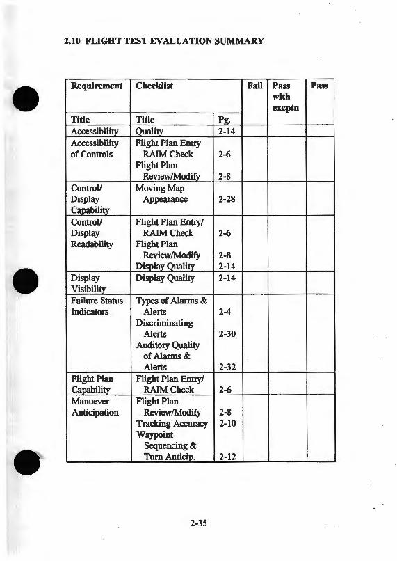
2.10 FLIGHT TEST EVALUATION SUMMARY
Requirement Checklist Fail Pass Pass with excptn
Title Title P!. Accessibility _Quality 2-14 Accessibility Flight Plan Entry of Controls RAIMCheck 2-6
Flight Plan Review/Modify 2-8
ControV Moving Map Display Appearance 2-28 Capability ControV Flight Plan Entry/ Display RAIMCheck 2-6 Readability Flight Plan
Review/Modify 2-8 Display Qualily 2-14
Display Display Quality 2-14 Visibility Failure Status Types of Alarms & Indicators Alerts 2-4
Discriminating Alerts 2-30
Auditory Quality of Alarms& Alerts 2-32
Flight Plan Flight Plan Entry/ Capability RAIMCheck 2-6 Manuever Flight Plan Anticipation Review/Modify 2-8
Tracking Accuracy 2-10 Waypoint
Sequencing & Turn Anticip. 2-12
2-35
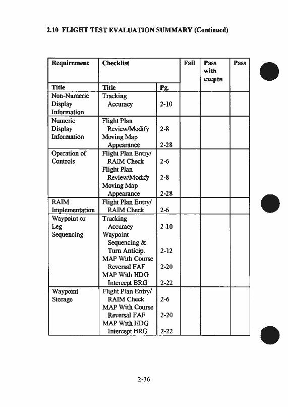
2.10 FLIGHT TEST EVALUATION SUMMARY (Continued)
Requirement Checklist Fail Pass Pass with excptn
Title Title Pg. Non-Numeric Tracking Display Accuracy 2-10 Information Numeric Flight Plan Display Review/Modify 2-8 Information Moving Map
A..,.,.......Cillce 2-28 Operation of Flight Plan Entry/ Controls RAIMCheck 2-6
Flight Plan Review/Modify 2-8
Moving Map Ayp<;<Uauce 2-28
RAIM Flight Plan Entry/ Implementation RAIMCheck 2-6 Waypointor Tracking Leg Accuracy 2-10 Sequencing Waypoint
Sequencing & Turn Anticip. 2-12
MAP With Course Reversal F AF 2-20
MAPWithHDG Intercept BRG 2-22
Waypoint Flight Plan Entry/ Storage RAIMCheck 2-6
MAP With Course Reversal F AF 2-20
MAPWithHDG Intercept BRG 2-22
2-36
2.10 FLIGHT TEST EVALUATION SUMMARY (Continued)
Checklist Fail Pass Pass with excptn
OVERALL RATING
OVERALL COMMENTS:
2-37/2-38

)> "'C "'C m z c 0 m en


APPENDIXT
TSO C129Al
Airborne Supplemental Navigation Equipment Using The Global Positioning System (GPS)
Tl
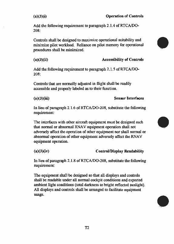
(a)(J)(i) Operation of Controls
Add the following requirement to paragraph 2.1.4 ofRTCA/D0-208:
Controls shall be designed to maximize operational suitability and minimize pilot workload. Reliance on pilot memory for operational procedures shall be minimized.
(a)(J)(ii) Accessibility of Controls
Add the following requirement to paragraph 2.1.5 of RTCA/D0-208:
Controls that are normally adjusted in flight shall be readily accessible and properly labeled as to their function.
(a)(J)(iii) Sensor Interfaces
In lieu of paragraph 2.1.6 ofRTCA/D0-208, substitute the following requirement:
The interfaces with other aircraft equipment must be designed such that normal or abnormal RNA V equipment operation shall not adversely affect the operation of other equipment nor shall normal or abnormal operation of other equipment adversely affect the RNA V equipment operation.
(a)(J)(iv) Control/Display Readability
In lieu of paragraph 2.1.8 of RTCA/D0-208, substitute the following requirement:
The equipment shall be designed so that all displays and controls shall be readable under all normal cockpit conditions and expected ambient light conditions (total darkness to bright reflected sunlight). All displays and controls shall be arranged to facilitate equipment usage.
T2
(a)(J)(v) Maneuver Anticipation
Add the following requirement to paragraph 2.1.1 0 of RTCA/D0-208:
For systems approved for non precision approaches (class AI equipment), maneuver anticipation (turning prior to the "to" waypoint) shall not be implemented at the missed approach fix or the missed approach holding fix.
(a)(J)(vi) Update Rate
In lieu of paragraph 2.1.11 of RTCA/D0-208, substitute the following requirement:
Navigation information used for display shall be updated at an interval of 1.0 second or less.
(a)(J)(vii) Numeric Display Information
In lieu of paragraph 2.2.1.1.1 ofRTCA/D0-208, substitute the following requirement:
1. Equipment certified to class A2 shall continuously provide either a display or electrical output with the following requirements:
a. The display shall be as accurate as the resolution required for the displayed full scale range, referenced to a centered CDI display (see table inparagraph (a)(3)(viii)).
b. The equipment shall provide a numeric display or electrical output of cross-track deviation to at least ± 20 nm (left and right). A minimum resolution ofO.l nm up to 9.9 nm and 1.0 nm beyond shall be provided. The display may be pilot selectable.
2. Equipment certified to class AI, shall, in addition to the requirements for class A2:
a. Provide a numeric (digital) display or electrical output of cross-track deviation to a resolution ofO.Ol nm for deviations less than 1.0 nm.
T3
(a)(J)(vii) Numeric Display Information (Continued)
b. Compute and display track angle error (T AE) to the nearest one degree. Track angle error is the difference between desired track and actual track (magnetic or true). In lieu of providing a numeric display of track angle error, non-numeric track angle error may be displayed in conjunction with the display required in paragraph (a)(3)(viii) of this TSO.
NOTE 1:
NOTE2:
While the numeric display need not be located with the non-numeric cross-track display (subparagraph 2. 2.1.1. 2) or in the pilot's primary field of view, flight technical e"or (FTE) can be reduced when the numeric display is integrated with the non-numeric display or is located within the pilot's primary field of view. Both digital cross track and track angle e"or have been shown to reduce FTE. This information should be displayed together (either within the CDU or remotely displayed near the non-numeric display) for better tracking performance.
The use of non-numeric cross track data integrated with non-numeric track angle e"or data into one display may provide the optimum of situation and control information for the best overall tracking performance.
T4
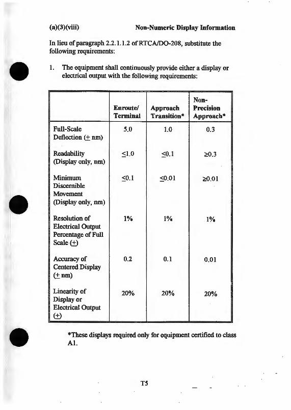
(a)(J)(viii) Non-Numeric Display Information
In lieu of paragraph 2.2.1.1.2 of RTCA/D0-208, substitute the following requirements:
1. The equipment shall continuously provide either a display or electrical output with the following requirements:
Non-En route/ Approach Precision Terminal Transition* Approach*
Full-Scale 5.0 1.0 0.3 Deflection (± nm)
Readability ~1.0 ~0.1 ~.3 (Display only, nm)
Minimum ~0.1 S0.01 ~.01 Discernible Movement (Display only, nm)
Resolution of 1% 1% 1% Electrical Output Percentage of Full Scale(±)
Accuracy of 0.2 0.1 0.01 Centered Display (±nm)
Linearity of 20% 20% 20% Display or Electrical Output (±)
*These displays required only for equipment certified to class AI.
T5
(a)(J)(viii) Non-Numeric Display Information (Continued)
2. The applicable non-numeric display information shall be automatically presented upon activation of the appropriate operating mode.
3. A means shall be provided for manual pilot selection of the available display sensitivities including those automatically selected by the system (overriding an automatically selected sensitivity, during an approach, shall cancel the approach mode annunciation). Additionally, the equipment shall display the non-numeric scale sensitivity.
4. In lieu of a linear lateral deviation scale for the final approach segment (final approach fix to missed approach point), an angular deviation display that emulates the nominal ILS localizer/MLS azimuth display resolution may be used, beginning with a full-scale cross-track deflection of ±().3 nm at the final approach fix decreasing to ±().0576 nm at the runway threshold.
(a)(J)(ix) Waypoint Entry
In lieu of paragraphs 2.2.1.5 and 2.2.1 . 9 of RTCA/D0-208, substitute the following requirements:
1. Equipment certified to class A2 shall at least provide the capability to manually enter and display (prior to its utilization in the flight plan) the coordinates of a waypoint in terms of latitude and longitude with a resolution ofO.l minute or better. If the equipment provides the ability to enter a waypoint as a range and bearing from another waypoint, the waypoint input resolution shall be 0.1 nm and 1 degree or better.
NOTE: Systems providing input resolution of only 0.1 minute may require modification in the future as changes to the National Airspace System occur.
T6
(a)(J)(ix) Waypoint Entry (Continued)
2. Equipment certified to class Al shall at least provide the capability to manually enter and display (prior to its utilization in the flight plan) the coordinates of a waypoint in terms of latitude and longitude with a resolution ofO.Ol minute or better. lfthe equipment provides the ability to enter a waypoint as a range and bearing from another waypoint, the waypoint input resolution shall be 0.1 nm and 0.1 degree or better.
(a)(J)(x) Waypoint Storage
In lieu of paragraph 2.2.1.6 of RTCA/00-208, substitute the following requirement:
1. The equipment shall provide an appropriately updatable navigational data base containing at least the following location information in terms of latitude and longitude with a resolution ofO.Ol minute or better for the area(s) in which IFR operations are to be approved: all airports, VORs (and VORT ACs), NDBs, and all named waypoints and intersections shown on route and terminal area charts, Standard Instrument Departures (SIDs), and Standard Terminal Arrival Routes (STARs).
NOTE: Manual entry/update of navigation data base data shall not be possible. (!'his requirement does not preclude the storage of "user defined data" within the equipment.)
2. Equipment certified to class Al, in addition to the requirements of paragraph (a) (3) (x)l., shall provide the following:
a. The equipment navigation data base shall also include all waypoints and intersections included in published nonprecision instrument approach (except localizer, LOA, and SDF) procedures.
T7
(a)(3)(x) Waypoint Storage (Continued)
b. The equipment shall store all waypoints, intersections, and/or navigation aids and present them in the correct order for a selected approach as depicted on published nonprecision instrument approach procedure charts. The sequence of waypoints shall consist of at least the following: selected initial approach fix (IAF), intermediate approach fix(es) (when applicable), final approach fix, missed approach point, and missed approach holding point. For procedures with multiple IAFs, the system shall present all IAFs and provide the capability for pilot selection of the desired IAF. Selection of the desired IAF shall automatically insert the remaining waypoints in the approach procedure in the proper sequence.
c. Waypoints utilized as a final approach fix or issued approach point in a non-precision approach procedure shall be uniquely identified as such to provide proper approach mode operation.
d. Modification of data associated with published instrument approach procedures by the user shall not be possible.
e. Waypoint data utilized in non-precision approach procedures shall be in terms of latitude and longitude and cannot be designated in terms of bearing (radial) and distance to/from a reference location.
f. When in the approach mode, except for holding patterns and procedure turns, the equipment must establish the desired flight path in terms of the path between defined endpoints up to the missed approach point
3. The equipment shall provide the capability for entering, storing, and designating as part of the active flight plan a minimum of nine discrete waypoints (including the active waypoint). In addition, for class AI equipment, it shall store and designate as part of the active flight plan the complete sequence of waypoints from the navigation data base necessary to complete the selected approach, including the missed approach.
T8
(a)(J)(x) Waypoint Storage (Continued)
4. Waypoints shall be coded in the navigation data base to identify them as "fly by" (turn anticipation pennitted) or "fly over" (turn anticipation not pennitted) as required by the instrument approach procedure, SID, or STAR. Waypoints which define the missed approach point and missed approach holding point in instrument approach procedures shall be coded as "fly over."
5. Navigation data bases shall meet the standards specified in sections 3, 4, and 5 ofRTCA/D0-200, "Preparation, Verification and Distribution of User Selectable Navigation Data Bases" and sections 2 through 7 ofRTCA/D0-201, "User Recommendations for Aeronautical Information Services."
(a)(J)(xi) Waypoint or Leg Sequencing
Add the following requirement to paragraph 2.2.1.7 ofRTCA/D0-208:
1. The equipment shall provide the capability to fly from the present position direct to any designated waypoint. Access to this feature shall be by means of a single action by the pilot. Selection of the desired "TO" waypoint may require additional actions.
2. The equipment shall provide the capability for accomplishment of holding patterns and procedure turns. Activation of this function shall at least:
a. Change automatic waypoint sequencing to manual.
b. Pennit the pilot to readily designate a waypoint and select a desired course (by means of a numerical keypad entry, HSI course pointer, CDI omni bearing selector, etc.) to or from the designated waypoint (TO/FROM mode operation is acceptable).
c. Retain all subsequent waypoints in the active flight plan in the same sequence.
T9
(a)(J)(xi) Waypoint or Leg Sequencing (Continued)
d. Permit the pilot to readily return to automatic waypoint sequencing at any time prior to the designated fix ("TO" waypoint) and continue with the existing flight plan.
3. Class Al equipment, unless incorporating or interfaced with an appropriate situational awareness display (i.e., an electronic map), shall be designed to prevent automatic waypoint sequencing from the missed approach waypoint to the missed approach holding waypoint. Except for equipment with an approved electronic map display, course guidance shall display an extension of the inbound track and distance from the missed approach waypoint until manual selection of the next desired waypoint.
(a)(J)(xii) Approach Mode Selection and Sequencing
Add the following requirement to RTCA/D0-208:
1. For accomplishment of non-precision approaches, when an · approach is included in the active flight plan, class Al equipment shall provide the following:
a. At a radial distance of 30 nm from the destination airport (not distance along the flight plan route), the equipment shall provide an approach enable alert. After display of this alert, a means shall be provided to enable the approach mode with a single action by the pilot. The approach mode shall not engage unless previously enabled by the pilot. Concurrent with the approach enable alert, a suitable means to alert the pilot of the need to manually insert the barometric pressure setting shall be provided (unless the automatic altitude input utilizes barometric corrected altitude data).
b. Upon activation of the approach mode, the equipment shall provide a smooth transition from 5 nm non-numeric display sensitivity to 1 nm sensitivity.
TlO

(a)(J)(xii) Approach Mode Selection and Sequencing (Continued)
c. At a distance of 3 run inbound to the final approach fix, the equipment shall provide an annunciation indicating an automatic non-numeric display sensitivity change will occur. If the approach mode was not previously activated, the approach enable alert shall be repeated.
d. At a distance of 2 run inbound to the final approach fix, the equipment shall:
i. Immediately transition from terminal integrity performance to approach integrity performance as specified in Table 2-l ofRTCND0-208.
ii. Provide a linear transition from 1 run nonnumeric display sensitivity to 0.3 run sensitivity at the final approach fix.
5. If the pilot manually sequences to the missed approach holding point, the equipment shall:
a. Transition from approach integrity performance to terminal integrity performance as specified in Table 2-1 of RTCA/D0-208.
b. Provide a smooth transition from 0.3 run non-numeric display sensitivity to 1 run sensitivity.
6. A means shall be provided for deselection of the approach mode with a single action by the pilot. Deselection of the approach mode shall:
a. Transition from RNA V (non-precision) approach integrity performance to terminal integrity performance as specified in Table 2-1 ofRTCA/D0-208.
b. Provide a smooth transition from 0.3 run non-numeric display sensitivity to 1 run sensitivity.
Til
(a)(J)(xii) Approach Mode Selection and Sequencing (Continued)
7. If the ability to perform DME arcs is provided, the equipment shall permit the pilot to readily accomplish such procedures in accordance with published non-precision approach procedures utilizing piloting techniques similar to those applicable to use of the reference DME facility.
(a)(J)(xiii) Failure/Status Indications
In lieu of paragraph 2.2.1.1 0 of RTCA/D0-208, substitute the following requirement:
The equipment shall indicate, independent of any operator action, the following:
1. By means of navigation warning flag on the navigation display:
a. The absence of power required for the navigation function.
b. Any probable equipment malfunction or failure affecting the navigation function.
c. Loss of navigation function.
d. For equipment certified to class Al, inadequate or invalid navigation data in the approach mode detected in accordance with RTCA D0-208 paragraph 2.2.1.13, Table 2-1, and paragraph (a) (3) (xv) of this TSO.
e. For equipment certified to class Al, the loss of the RAIM detection function in the approach mode at the final approach fix.
f. For equipment certified to class AI, loss of the RAIM detection function in the approach mode, after passing the final approach fix. However, the navigation warning flag shall not be displayed until the RAIM detection function is lost for more than five minutes.
Tl2
(a)(J)(xiii) Failure/Status Indications (Continued)
2. By means of an appropriately located annunciator:
a. When RAIM is not available, inadequate navigation data due to poor space vehicle geometry such that the probability that navigation error exceeds the position integrity performance requirements in RTCA/D0-208 (Table 2-1) is greater than or equal to .05.
b. The RAIM function detects a position error that exceeds the GPS position integrity performance requirements in RTCA/D0-208 (Table 2-l).c.
c. Loss of the RAIM function. Display of the integrity annunciation may be delayed for a period of time consistent with the requirements of paragraph (a) (3) (xiv) of this TSO.
d. For equipment certified to class AI, predicted unavailability of the RAIM detection function as specified in paragraph (a)(3)(xv)l.
e. For equipment certified to class AI, when operating in the approach mode without RAIM and navigation performance is degraded because HOOP exceeds 4.0.
T13
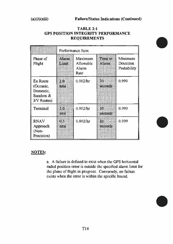
(a)(J)(xiii) Failure/Status Indications (Continued)
TABLE 2-1 GPS POSITION INTEGRITY PERFORMANCE
REQUIREMENTS
En Route (Oceanic, Domestic, Random& JNRoutes)
Tenninal
RNAV Approach (NonPrecision)
NOTES:
Minimum Detection Probability
0.999
0.999
0.999
a. A failure is defined to exist when the GPS horizontal radial position error is outside the specified alarm limit for the phase of flight in progress. Conversely, no failure exists when the error is within the specific bound.
T14
(a)(J)(xiii) Failure/Status Indications (Continued)
b. Maximum allowable alarm rate refers to the total alarm rate with the equipment in normal operation with no satellite malfunction. It is anticipated that most integrity alarms, even though rare, will be induced by the normal effects of selective availability, propagation uncertainties and receiver noise. Alarms due to unannounced satellite malfunctions are expected to be extremely rare. The alarm rate specified allows an average of only one alarm per 15,000 two-minute intervals. (Correlation times of selective availability are assumed to be approximately two minutes.) The specified alarm rate does not include those periods when the integrity system is declared inoperable due to poor detection geometry of the satellites. This alarm rate applies globally at all times regardless of the constellation at hand.
c. Time to alarm is defined to be the maximum allowable elapsed time from the onset of the failure, as defined in (a.) above, until the time that the integrity alarm is annunciated.
d. Detection probably is defined as 1 - miss probability. Miss probability is the conditional probability that the detection algorithm decides that a failure is not present when, in fact, a failure exists. The integrity system shall meet the specified detection probability globally at all times for single satellite failures, except for those conditions where integrity cannot be assured and the flag is displayed accordingly (see subparagraph 2.2.1.13.2 b). The specified detection probability shall apply regardless of the constellation at hand. This probability is such as to provide an undetected failure rate of 3.8E-8 per flying hour, provided that the rate of unannounced gradual satellite failures is no greater than one failure per nine months for the entire 24-satellite constellation. (This is the equivalent of an MTBF of 18 years for this type of failure for individual satellites.)
Tl5
(a)(J)(xiii) Failure/Status Indications (Continued)
e. Equipment manufacturers have the option of using more stringent requirements than those given in this table. For example, some manufacturers may choose to have only two levels of alarm limits, 0.3 nmi for non-precision approach and 1.0 nmi for all other phases of flight. Such a deviation is within the intent of this table.
f. All of the specifications given in this table must be met with selective availability in progress on all satellites being used. See subparagraph 2.5.2.5 for the assumptions about selective availability that are to be used for testing.
These failure/status indication(s) shall occur independently of any operator action.
NOTE: It is impractical for the operator to monitor, unaided, the changing parameters that affect accuracy. Therefore, the equipment should monitor those parameters for degraded performance that may result from propagation, reception, geometry, selective availability (SA) or other effects to the extent possible and be capable of automatic compensation, deselection or manual deselection following annunciation of degraded performance.
T16
(a)(3)(xiii) Failure/Status Indications (Continued)
3. Additional navigation data (such as distance to waypoint, time to waypoint, ground speed, etc.) shall be removed or flagged when the adequacy of navigation information upon which this data is based cannot be assured.
NOTE: Presentation of a failure/status annunciation does not require removal of navigation information from the navigation display. Consideration should be given to continue display of navigation information concu"ent with the failure/status annunciation when conditions wa"ant.
NOTE: It is impractical for the operator to monitor, unaided, the changing parameters that affect accuracy. Therefore, the equipment should monitor those parameters for degraded performance that may result from propagation, reception, geometry, selective availability (SA) or other effects to the extent possible and be capable of automatic compensation, deselection, or manual deselection following annunciation of degraded performance.
4. Approach mode status/annunciations. Equipment certified to class AI shall provide:
a. An annunciation that the approach mode is enabled.
b. An annunciation that the system is in the approach mode (RAIM in RNA V (non-precision) approach integrity performance and non-numeric display in approach sensitivity).
c. An annunciation of impending automatic non-numeric display sensitivity change to approach sensitivity.
d. An annunciation to alert the pilot of the need to manually insert the barometric pressure (unless automatic altitude input utilizing barometric corrected altitude data is available).
e. An annunciation to alert the pilot to enable the approach mode.
Tl7
(a)(J)(xiv) Annunciation of Integrity Alarm
Delete the second sentence of the opening paragraph 2.2.1.13 .2 of RTCA/D0-208 and replace with:
1. A separate and distinctive indication shall be raised in each of the following two circumstances.
Add the following requirement to paragraph 2.2.1.13.2 of RTCA/D0-208:
a. In order to minimize nuisance integrity alarms when system navigation accuracy is otherwise not in doubt, properly substantiated compensating features (such as clock coasting, inertial data, other sensors, etc.) may be incorporated into the system. The alarm under these conditions may be delayed for a period of time consistent with the worst cases of undetected clock drift or other failures that would cause the position error to exceed the accuracy required for that phase of flight. The applicant must develop appropriate test procedures to demonstrate that the proposed compensating features provide the required level of navigation accuracy and integrity.
(a)(J)(xv) RAIM Implementation
Add the following requirement to paragraph 2.2.1.13.3 of RTCA/D0-208:
1. The RAIM function shall provide terminal integrity performance as specified in Table 2-1 ofRTCA/D0-108 within 30 nm of the departure and destination points. In addition, approach mode (class A1 equipment) integrity performance shall be provided from 2 nm prior to the final approach fix to the missed approach point. En route integrity performance shall be provided during other conditions.
T18
(a)(J)(xv) RAIM Implementation (Continued)
2. The equipment shall automatically select the appropriate RAIM integrity performance requirements.
3. Equipment certified to class AI shall:
a. Upon transition to approach integrity, automatically verify (via the RAIM prediction function) that satellite vehicle geometry will be suitable during non-precision approaches to enable the RAIM function to be available upon arrival at the final approach fix and the missed approach point. Satellite vehicle failures (detected and deselected by the equipment) that occur after the final approach fix which prevent the RAIM detection function do not require annunciation for a period of 5 minutes.
b. Provide the pilot, upon request, a means to determine if RAIM will be available at the planned destination at the estimated time of arrival (ETA) (within at least ±15 minutes computed in intervals of 5 minutes or less). Once complete almanac data has been received, this capability shall be available at any time after the destination point and estimated time of arrival at that point are established. The availability of corrected barometric altitude (either by automatic or manual altimeter setting input) may be assumed for this purpose (for the purposes of this calculation, an acceptable value of sbaro is 50 meters).
c. Display, upon request, RAIM availability at the ETA and over an interval of at least ±15 minutes computed in intervals of 5 minutes or less about the ETA.
(a)(J)(uii) Flight Plan Capability
Add the following requirement to RTCA/D0-208:
The equipment shall provide the capability to create, display, and edit a flight plan consisting of a minimum of 9 waypoints. A means shall be provided to readily display each waypoint, individually or together, of the active flight plan (in sequence) for review.
T19ff20


:z:1 :::D
~ c 0
I
N 0 CXI

APPENDIXR
RTCA/D0-208
Minimum Operational Performance Standards For Airborne Supplemental Navigation
Equipment Using Global Positioning System (GPS)
Rl
2.0
2.1
Equipment Performance Requirements and Test Procedures
General Requirements
The following general requirements shall be met by all RNA V equipment.
2.1.4 Operation of Controls
Controls intended for use during flight shall be designed to minimize errors and, when operated in all possible combinations and sequences, shall result in a condition whose presence or continuation would not be detrimental to the continued performance of the equipment.
2.1.5 Accessibility of Controls
Controls that are not normally adjusted in flight shall not be readily accessible to the operator.
2.1.7 Control/Display Capability
A suitable interface shall be provided to allow data input, data output and control of equipment operation. It shall be possible for the operator to manually select waypoint(s). The control/display shall be operable with the use of only one hand.
2.1.10 Maneuver Anticipation
Maneuvers such as turns to intercept a new course; transitions to an established direct-to leg; changes in climb, descent, level-off or change of ascent/descent angle must be anticipated when operating in the airspace. This anticipation may be accomplished through computational techniques within the equipment, operational procedures or a combination ofboth. Regardless of the method chosen to implement maneuver anticipation, aircraft performance envelopes directly influence the effectiveness of this requirement (see Subsection 3.2 and Appendix H).
R2

2.2
2.2.1
2.2.1.2
2D RNA V Functional and Accuracy Requirements - Standard Conditions
Equipment Functional Requirements
Waypoint Distance Display
Distance to the waypoint shall be displayed on demand with a resolution of 0.1 nmi or better up to a range of 99.9 nmi from the waypoint, and it shall be 1.0 nmi or better at greater ranges. The equipment shall have the capability to display values of distance to waypoints of at least 150 nmi for TO-FROM equipment and at least 260 nmi for TO-TO equipment.
NOTE: For en route operation with random route clearance, a much greater distance between waypoints may be desirable.
2.2.1.3 TO-FROM Indication
For TO-FROM equipment, a continuous display or electrical output shall be provided to show whether the aircraft is behind or ahead of the active waypoint relative to an imaginary line perpendicular to the desired path and passing through the active waypoint.
For TO-TO equipment, which allows overflying of the active waypoint, a continuous display or electrical output shall be provided to show when the aircraft has passed an imaginary line perpendicular to the desired path and is passing through the active TO waypoint.
2.2.1.4 Flight Path Selection
The equipment shall provide a means of selecting and displaying a flight path defined by two waypoints. Additionally, if a TO-FROM mode is provided, the equipment shall provide a means of selecting and displaying an active waypoint and a desired course through the waypoint. The entry and display resolution of such a selected course shall be one degree or finer.
NOTE: It is assumed herein that the selected course is entered digitally. If analog techniques are used, it shall be demonstrated that the e"or in selecting the course does not exceed 0.5 degree.
R3
2.2.1.7 Waypoint or Leg Sequencing
Means shall be provided, either manually or automatically, to utilize a series of stored waypoints in any selected order. Provisions shall be made to display the identification of the active waypoint and to preview the next waypoint or leg available for activation. The active and stored waypoints need not be displayed simultaneously. Means shall be provided to indicate whether or not the displayed waypoint is the active waypoint.
2.2.1.8 Position Display
The computed aircraft position shall be available for display in terms of range and bearing to or from the active or parent waypoint. Resolution of range and bearing shall be at least 0.1 nmi and 1.0 degree up to 99.9 nmi, then at least 1.0 nmi and 1.0 degree beyond. Some equipment may also display this information in latitude/longitude. lf displayed, it shall have a resolution of at least 0.1 minute.
NOTE: The intent of this requirement is to permit the operator to provide this information to ATC upon request.
2.2.1.11 Satellite Selection and Indication
The equipment shall provide the capability to:
a. automatically select satellites for use in navigational computation.
b. determine suitability of each satellite for use by data content including all appropriate parameters such as "health" status, complete almanac data, correct ephemeris and correctness of parity.
c. remove satellite from use when it is not suitable.
d. provide a warning consistent with the integrity requirements for the intended phase of flight.
R4
2.2.1.12 Equipment Computational Response Time After Waypoint Entry
The time lag between time of waypoint data input and display of navigation guidance derived from the data shall not exceed five seconds.
NOTE: Equipment outputs may be filtered or "eased on" consistent with desired aircraft dynamics and operating conditions.
2.2.1.13 Integrity Alarm for GPS Receivers
2.2.1.13.1 General Integrity Requirements
The equipment shall provide integrity assurance. Regardless of the method used to ensure integrity, the integrity system shall meet the general specifications given in Table 2-1. The explanatory notes accompanying Table 2-1 are an essential part of the table.
2.2.1.13.2 Annunciation of Integrity Alarm
The GPS equipment must give a clear and timely annunciation of alarm for each phase of flight being conducted. The alarm shall be raised in either of the following two circumstances:
a. The integrity monitoring equipment indicates that the GPS horizontal radial position error is outside the specified alarm limit for the phase of flight in progress.
b. There exists an absence of a positive integrity check of the navigation solution for any reason, be it poor satellite geometry, inadequate satellite redundancy, potential equipment failure, etc.
The term "timely" means that the alarm annunciation shall take place within the specified time to alarm for the phase of flight in progress.
No special form for the alarm presentation is specified in this document, except that for non-precision approach there must be an annunciation on the primary navigation display that indicates invalid integrity verification for this phase of flight.
R5
2.2.1.13.3 RAIM Implementation
GPS equipment manufacturers have the option of using any RAIM technique that will meet the specifications given in Table 2-1 and other specifications stated in subparagraph 2.2.1.13.2 of this document. The equipment manufacturer shall be required to demonstrate compliance with these specifications (see subparagraph 2.5.2.5).
2.3
2.3.1
(VNA V) Functional and Accuracy Requirements - Standard Conditions
Equipment Functional Requirements
In addition to the 2D RNA V requirements listed in Subsection 2.2, the following set of functional requirements are those that VNA V equipment shall meet, as a minimum, to operate safely and efficiently. These are established to ensure acceptable operation in the vertical plane regardless of VNA V equipment type.
2.3.1.1 VVaypointAltitude
The equipment shall provide a manual means of entering and storing an altitude directly associated with the active waypoint. The resolution of waypoint altitude entry shall be 100 ft. or better for en route and terminal flight phases and 10 ft. or better for the approach phase. This requirement shall be met over the altitude range as specified by the equipment manufacturer.
2.3.1.2 Vertical Path Deviation
The equipment shall continuously provide an electrical output or other means for determination of the magnitude and direction of the vertical deviation from the desired vertical profile. Means of determining the vertical deviation shall provide not less than ±500 ft. range for en route and terminal, and ±150 ft. for approach, and with resolutions not greater than 100ft. and 30ft., respectively.
R6
2.3.1.3 Vertical Profile
· a. For ascents, if the capability is provided in the system, the equipment shall provide a reference vertical profile that aids in compliance with altitude constraints at waypoints.
3.0
3.1
b. For level flight segments, if the capability is provided in the system, the equipment shall provide a reference vertical profile that aids in compliance with the specified altitude.
c. For descent segments prior to the final approach fix waypoint, the equipment shall provide a reference vertical profile that aids in compliance with altitude constraints at waypoints. Straight line profiles may be used but are not required.
d. In the approach phase starting with the final approach fix waypoint, the equipment shall provide a means of specifying a constant altitude rate (linear variation of along-track distance with altitude vertical profile) to be followed. This profile may take the form of a line connecting two waypoints with their associated altitudes or a line terminating at or emanating from a specified waypoint (with its associated altitude) at a specific gradient angle.
e. For equipment that specifies gradient angles, the angle resolution shall be 0.1 degree or better.
Installed Equipment Performance
Equipment Installation
3.1.1 Accessibility
Controls installed for in-flight operation shall be readily accessible from the pilot's seated position.
R7

3.1.2 Display Visibility
The appropriate flight crew member(s) shall have an unobstructed view of displayed data when in the seated position. Displays used for maneuver anticipation and for failure annunciation shall be located within the pilot's primary field of view. The brilliance of any display shall be adjustable to levels suitable for data interpretation under all cockpit ambient light conditions ranging from total darkness to reflected sunlight.
The approach mode annunciation and distance to waypoint in the approach mode shall be clearly visibfe to the pilot with the least practicable deviation from his normal position and from his line of vision when he is looking forward along the flight path.
NOTE: Visors, glareshields or filters may be an acceptable means of obtaining daylight visibility.
3.1.4 Inadvertent Turnoff
There shall be a minimal risk of inadvertent turnoff.
3.3.5 Warm-Up Period
Unless otherwise specified, all tests shall be conducted after the manufacturer's specified warm-up (stabilization) period. This period shall not exceed 15 minutes.
4.0 Operational Characteristics
4.1 Required Operational Characteristics
4.1.2 Navigation Displays
Each of the required displays for determining position and relationship of the airplane to the desired course shall be available for use.
4.1.3 Navigation Controls
Each cockpit control required for proper operation of the equipment shall be available for use.
R8

APPENDIXFl
FAA-AC-20-138
Airworthiness Approval Of Global Positioning System (GPS) Navigation
Equipment For Use As A VFR and IFR Supplemental Navigation System
Fl
4.
6.
7.
BACKGROUND
g. General Operational Limitations.
(3) IFR Navigation Equipment. GPS equipment for IFR navigation is for use as a supplemental navigation system. The installation of GPS equipment does not affect the requirement for primary means of navigation appropriate to the route intended to be flown. Within the contiguous United States, Alaska, Hawaii, and surrounding coastal waters, this requirement can be met with an operational, independent VOR receiver. Additional navigation equipment redundancy may be required for operation in oceanic and remote airspace.
SYSTEM ACCURACY
b. Flight Technical Error {FTE). Since FfE factors are normally beyond the control of equipment manufacturers or installers, these error sources are not included in the accuracy specifications in paragraph 6a(l ). The FAA has determined that when properly installed in an aircraft, Class A equipment meeting the operational and display characteristics contained in this AC and TSO-C129 provided for acceptable values of FTE. FTE should not exceed 1.0 nmi for en route, 1.0 nmi for approach transition, or 0.25 nmi for approach operating modes on a 95 percent basis.
AIRWORTHINESS CRITERIA FOR GPS INSTALLATIONS USED AS A
SUPPLEMENTAL NAVIGATION SYSTEM LIMITED TO VISUAL
FLIGHT RULES (VFR) ONLY
a. Application Process.
(1) The initial (first-time airworthiness approval) certification of a GPS navigation system should be accomplished via the TC or STC approval process.
F2
(2) Subsequent (follow-on) installations of the same GPS navigation system (hardware and software) in other aircraft are approved using a less extensive evaluation process since the basic engineering design of the GPS equipment has already been evaluated. Approval of follow-on installations may be accomplished via the TC, STC, or FAA Form 337 process. The extent of required regulations depends upon the degree of integration of the GPS system with other aircraft systems, the similarity between the initial and follow-on aircraft models, and other changes that may have been incorporated in the GPS navigation system. The decision to allow an applicant to use FAA approved engineering data in support of an FAA Form 337 approval is left to the field inspector's judgement. The FAA Airworthiness Inspector's Handbook (FAA Order 8300.10) provides guidance applicable to GPS equipment installations.
b. Airworthiness Considerations. GPS equipment approved for VFR use only does not require TSO-Cl29 authorization, however it must at least meet the en route/terminal system accuracy criteria (0.124 nmi, 95 percent probability) contained in paragraph 6a of this AC. Airworthiness considerations should include the following.
(4) Navigation Source Annunciator. A navigation source annunciator is provided on or near each affected display if the GPS installation supplies any information to displays such as a horizontal situation indicator (HSI), course deviation indicator (CD I), distance display, electronic map, etc., which can also display information from other systems normally used for aircraft navigation.
(7) System Controls. Displays and Annunciators. All displays, controls, and annunciators must be easily readable under all normal cockpit conditions and expected ambient light conditions (total darkness to bright reflected sunlight). Night lighting provisions must be consistent with other cockpit lighting. All displays and controls should be arranged to facilitate equipment usage. Controls that are normally adjusted in flight shall
F3
be accessible and properly labeled as to their function. System controls and displays should be designed to maximize operational suitability and minimize pilot workload. System controls should be arranged to provide adequate protection against inadvertent system turnoff. Reliance on pilot memory for operational procedures shall be minimized.
(8) Navigation/Integrity Annunciation. The GPS equipment should indicate, independent of any operation action:
(i) The following conditions by means of a navigation warning flag on the navigation display:
(A) The absence of power necessary for the navigation function.
(B) Probable equipment malfunctions or failures affecting the navigation function.
(C) Loss of navigation function.
(ii) If an integrity monitoring function such as RAIM is provided, an appropriately located annunciator shall be provided to indicate loss of the integrity monitoring function.
Note 1: For equipment not incorporating an external navigation display (CDI, HSI, etc.) complete blanking of the Control Display Unit (CDU) display is acceptable.
Note 2: Presentation of a failure/status annunciation (flag or integrity annunciation) does not require removal of navigation information from the navigation display.
(9) Autopilot/Flight Director Coupling. The GPS navigation system may be coupled to autopilot and/or . flight director system, if a deviation or steering output that is compatible with the copilot/flight director system is provided and no unusual interface is required.
F4
(10) VFR Limitation Placard. A placard stating "GPS limited to VFR use only" must be installed in clear view of, and readable by, the pilot.
c. VFR Airworthiness Approval. There are two types of VFR airworthiness approvals which refer significantly as to test requirements and data analysis . .
(1) First-Time VFR Airworthiness Approval Criteria (for a Particular Type of GPS Equipment). This type of approval refers to the very first time an applicant presents a particular (hardware and software configuration) model GPS navigation system for FAA airworthiness installation approval and certification for VFR navigation use. The first approval of a particular GPS navigation system must be accomplished through the TC or STC process. Each new model of GPS equipment or significant changes (hardware or software) to existing equipment shall undergo the same approval process as the original equipment unless it can be shown by analysis and tests acceptable to the administrator that the new model will function as well or better than the approved equipment. The first-time approval is conducted in four phases:
(i) Lab/Bench Tests and Equipment Data Evaluation. This phase consists of the following:
(A) Review of the manufacturer's procedures for development of software and review of supporting documentation in accordance with the guidelines of paragraph 7b(5) ofthis AC.
(B) Analysis of failure modes and annunciations.
(C) Review of reliability data to establish that all probable failures affecting the navigation function are detected.
(D) Review of installation and maintenance manuals.
(E) Evaluation of the operator's manual (pilot's guide).
FS
(iv) Flight Test Evaluations. Flight tests are conducted to verify proper operation and accuracy of the GPS equipment as installed in the aircraft. Flight tests should include at least the following:
Note: Required flight evaluations for the first-time airworthiness approval of a particular GPS system are accomplished by the cognizant Aircraft Certification Office (ACO) unless specific tests are delegated by the ACO to a flight test pilot designated engineering representative (DER).
(A) Evaluation of installed GPS navigation system to verify that it is functioning properly, safely, and operates in accordance with the manufacturer's specifications.
(B) Evaluation of steering response while the autopilot and/or flight director coupled to the GPS equipment during a variety of different track and mode changes. All available display sensitivities should be evaluated.
(C) Evaluation to verify the GPS installation does not adversely affect other onboard equipment (this test may be partially accomplished as a ground test).
(D) Validate GPS navigation system accuracy by at least 5 low altitude overflights of one or more surveyed locations (ensure survey point coordinates are relative to WGS-84/NAD-83). An acceptable method of conducting this accuracy demonstration is to accomplish low altitude (less than 100 feet AGL) overflight of a runway threshold and record the GPS position as the aircraft crosses the threshold. The system accuracy is the distance between the coordinate position of the surveyed location (runway threshold). Runway threshold coordinates may be obtained from the airport operator. If coordinate data conversion WGS-84/NAD-83 is necessary, contact the National Flight Data Center at (202) 267-9277.
F6

8.
(E) Evaluation of the accessibility of all controls pertaining to the GPS installation.
(F) Evaluation of the visibility of the controls, displays, and annunciators relating to the GPS installation during day and night lighting conditions. No distracting cockpit glare or reflections may be introduced and all controls must be illuminated for identification and ease of use. Flight lighting shall be consistent with other cockpit lighting.
a. Application Process.
AIRWORTHINESS CRITERIA FOR GPS INSTALLATIONS USED AS A
SUPPLEMENTAL NAVIGATION SYSTEM UNDER INSTRUMENT
FLIGHT RULES (IFR)
(1) The initial (first-time airworthiness approval) certification of a GPS navigation or sensor system requires extensive engineering and flight test evaluations and must be accomplished via the TC or STC approval process.
(2) Subsequent (follow-on) installations of the same GPS navigation system (hardware and software) in other aircraft are approved using a less extensive evaluation process since the basic engineering design of the GPS equipment has already been evaluated. Approval of follow-on installations may be accomplished via the TC, STC, or FAA Form 337 process. The extent of required evaluations depends upon the degree of integration of the GPS system with other aircraft systems, the similarity between the initial and follow-on aircraft models, and other changes that may have been incorporated in the GPS navigation system. The decision to allow an applicant to use FAA approved engineering data in support of an FAA Form 337 approval is left to the field inspector's judgment. The FAA Airworthiness Inspector's Handbook (FAA Order 8300.10) provides
F7
guidance applicable to GPS equipment installations. Changes to software accomplishing navigation, integrity, or availability functions or significant changes to operating limitations cannot be accomplished using the FAA Form 337 process.
b. Airworthiness Considerations. GPS navigation equipment approved as a supplemental navigation system for oceanic and remote en route, domestic en route, terminal, and nonprecision instrument approach (except localizer, LOA, and SDF) operations does not require TSO-Cl29 authorization, however it must meet the minimum navigation performance and operation standards of Class A1 or A2 equipment, as applicable, specified in TSO-C129 and this AC. Airworthiness considerations should include the following:
(1) System Integrity and Software Development. Loss of navigation information is considered to be a major failure condition for the aircraft as defined in AC 25.1309-IA; AC 23.1309-A; AC 27-1; or AC 29-2A, as applicable to the aircraft. Providing/presenting hazardously misleading information to the flight crew is also considered to be a major failure condition for the aircraft. GPS navigation data is considered to be hazardously misleading when unannunciated position errors exist that are greater than those specified by the GPS position integrity performance requirements in Table 2-1 ofRTCA/D0-208. The applicant should conduct a safety assessment of the GPS equipment installation to verify that design errors and failure modes that produce major failure conditions are improbable.
(2) Display Format/Operating Procedure Changes. Changes to navigational display formats and navigation/function operating procedures (implemented through hardware or software) may constitute major changes requiring additional evaluation.
(3) Location of the GPS Display. Each display element (i.e., the cross track deviation display (COl), horizontal situation indicator (HSI), map display, etc.), used as a primary flight instrument in the guidance and control of
F8
the aircraft, for maneuver anticipation. or for failure/status/integrity annunciation. shall be located where it is visible to the pilot (in the pilot's primary field of view) with the least practicable deviation from the pilot's normal position and line of vision when looking forward along the flight path.
Note 1: CDI displays contained in the CDU will most likely not be acceptable for IFR operations.
Note 2: Flight technical error (FfE) can be reduced when numeric display information is integrated with the nonnumeric display or is located within the pilot's primary field of view. Both digital cross track and track angle error have been shown to reduce FfE. This information should be displayed together (either within the CDU or remotely displayed near the non-numeric display) for better tracking performance. The use of non-numeric cross track data integrated with non-numeric track angle error data into one display may provide the optimum of situation and control information for the best overall tracking performance.
(4) Failure Protection. Any probable failure of the airborne GPS navigation system shall not degrade the normal operation of other required equipment or create a flight hazard. Likewise, normal operation of the GPS equipment installation shall not adversely affect the performance of other aircraft equipment. The interfaces with other aircraft equipment must be designed such that normal or abnormal GPS equipment operation shall not adversely affect the operation of other equipment nor shall normal or abnormal operation of other equipment adversely affect the GPS equipment operation.
(6) Electromagnetic Compatibility. The GPS navigation system should not be the source of objectionable electromagnetic interference, nor be adversely affected by electromagnetic interference from other equipment in the aircraft.
F9
(8) System Controls. Displays and Annunciators. All displays, controls, and annunciators must be readable under all normal cockpit conditions and expected ambient light conditions (total darkness to bright reflected sunlight). Night lighting provisions must be compatible with other cockpit lighting. All displays and controls must be arranged to facilitate equipment usage. Controls that are normally adjusted in flight shall be accessible and properly labeled as to their function. System controls and displays shall be designed to maximize operational suitability and minimize pilot workload. System controls shall be arranged to provide adequate protection against inadvertent system turnoff. Reliance on pilot memory for operational procedures shall be minimized.
(9) Navigation Data Base. The GPS equipment shall incorporate an appropriately updatable navigation data base (in the WGS-84 or NAD-8 coordinate datum) containing at least the following location information in terms oflatitude and longitude with a resolution ofO.Ol minute or better for the area(s) in which IFR operations are to be conducted: all airports, VORs (and VORTACs), NDBs, and all named waypoints and intersections shown on en route and terminal area charts, Standard Instrument Departures (SIDs) and Standard Terminal Arrival Routes (STARs). For Class AI equipment, the navigation data base must also include all waypoints and intersections included in published non-precision instrument approach (except localizer, LDA, and SDF) procedures. Instrument approaches must be conducted using a current data base. User entry or modification of navigation data base data shall not be possible. (This does not preclude the storage of "user defined data" within the equipment.) Additional data base coding, storage, and approach waypoint presentation requirements as specified in TSO-Cl29 must be provided. Navigation data bases shall meet the standards specified in sections 3, 4, and 5 ofRTCA/D0-200, "Preparation, Verification and Distribution of User Selectable Navigation Data Bases" and sections 2 through 7 ofRTCA/D0-201, "User Recommendations for Aeronautical Information Services."
FlO
(10) Pressure/Barometric Altitude Inputs. An appropriate input of pressure and/or barometric altitude must be provided to the GPS equipment.
c. IFR Airworthiness APProval. There are two types of IFR airworthiness approval which differ significantly as to test requirements and data analysis.
(1) First-Time IFR Airworthiness Approval (for a Particular Type of GPS Equipment). This type of approval refers to the very first time an applicant presents a particular (hardware and software configuration) model GPS navigation system for FAA airworthiness installation and approval and certification for IFR navigation use. The first approval for a particular GPS navigation system must be accomplished through the Type Certificate (TC) or Supplemental Type Certificate (STC) process. Each new model of GPS equipment or significant changes (hardware or software) to existing equipment shall undergo the same approval process as the original equipment unless it can be shown by analysis and tests acceptable to the administrator that the new model will function as well or better than the approved equipment. A first-time approval is conducted in four phases:
(i) Lab/Bench Tests and Equipment Data Evaluation. This phase consists of the following:
(C) Verification of compliance with the minimum performance and operation standards applicable to Class A equipment specified in TSO-C129.
(D) Analysis of failure modes and annunciations.
(F) Evaluation of the ease of use of the controls and of the viewing ease (e.g., brightness, contrast, intensity, dimming, etc.) of the displays and annunciations from a human factors point of view.
(H) Evaluation of the operator's manual (pilot's guide).
Fll
(ii) Aircraft Installation Data Evaluation. Normally the manufacturer of the GPS equipment will provide an aircraft as a test bed for the first time installation approval. This approval will serve as a basis for subsequent installation approvals regardless of aircraft type or model. The following assessments are to be made:
(B) Evaluation of the cockpit layout of the installed equipment with emphasis on equipment controls, applicable circuit breakers (labels and accessibility), switching arrangement, and related indicators, displays, annunciators, etc.
(iv) Flight Test Evaluations. The flight tests are conducted to verify proper operation and accuracy of the GPS system in the aircraft. Flight tests should include at least the following:
Note: Required flight evaluations for the first-time airworthiness approval of a particular GPS system are accomplished by the cognizant Aircraft Certification Office (ACO) unless specific tests are delegated by the ACO to a Flight Designated Engineering Representative (DER).
(A) Evaluation of the overall operation of the GPS equipment is to include at least the following: the ability to readily create and modify a flight plan, perform "DIRECT TO" functions, hold a designated waypoint, intercept and track to or from a waypoint on a selected course, turn anticipation, waypoint sequencing, and the general presentation of navigational data (depiction of the "TO" waypoint, distance to waypoint, estimated time of arrival, estimated time en route, ground speed, etc.).
(B) Review of various failure modes and associated annunciations, such as loss of electrical power, loss of signal reception, GPS equipment failure, autopilot/flight director response to GPS flags, etc.
Fl2
(C) Evaluation of steering response while autopilot and/or flight director is coupled to the GPS equipment during a variety of different track and mode changes. This evaluation shall include, as applicable, transition from en route to approach, transition to approach modes and vice-versa. Additionally, all available display sensitivities shall be evaluated.
(D) Evaluation of displayed GPS navigation parameters on interfaced cockpit instruments such as HSI, CDI, distance display, electronic flight instruments system (EFIS), moving maps, fuel management systems, etc.
(G) Evaluation of the accessibility of all controls pertaining to the GPS installation.
(H) Evaluation of the visibility of the controls, displays, and annunciators relating to the GPS installation during day and night lighting conditions. No distracting cockpit glare or reflections may be introduced and all controls must be illuminated for identification and ease of use. Night lighting shall be consistent with other cockpit lighting.
(I) Analysis of crew workload when operating the GPS equipment in association with other piloting requirements.
(J) Validate GPS accuracy in each operating mode by at least 5 low altitude overflights of one or more surveyed locations (ensure survey point coordinates are relative to WGS-84 or NAD-83). An acceptable method of conducting this accuracy demonstration is to accomplish low altitude (less than 100 feet AGL) overflight of a runway threshold and record the GPS position as the aircraft crosses the threshold. The system accuracy is the distance between the coordinate position determined by the GPS and the
Fl3
coordinate position of the surveyed location (runway threshold). Runway threshold coordinates may be obtained from the airport operator. If coordinate data conversion to WGS-84/NAD-83 is necessary, contact the National Flight Data Center at (202) 267-9277.
(K) Verify continuity of navigation data during normal aircraft maneuvering including holding patterns and turns at up to at least 30 degrees of bank for one minute.
(L) Verify that flight technical error (FfE) can be maintained at less than 1. 0 nmi for en route, 1. 0 nmi for approach transition, and 0.25 nmi for approach operating modes both with and without autopilot and /or flight director use, as applicable.
(M) For equipment approved for approach, conduct a sufficient number of approaches and transitions from en route to terminal to approach operations using the navigation data base to verify proper operation of the GPS navigation system in the approach environment. This evaluation should include at least: tum
anticipation, waypoint sequencing, display sensitivity changes, annunciations, procedure turns at the final approach fix (F AF), holding patterns at the missed approach holding fix, transitions from TO-FROM operation to TO-TO operation, heading legs after the initial approach fix (IAF) to intercept the final approach course both before and after the F AF, and DIRECf TO operation before and after the IAF.
(2) Follow-on IFR Airworthiness Installation Approvals. This type of approval refers to installation approvals after a first time airworthiness approval of the particular GPS equipment has been issued. Follow-on approvals may use the first time airworthiness approval, which was either a TC or an STC, as a basis for installation approval.
Fl4
(iii) Conduct a data evaluation similar to that outlined in paragraph 8c(l)(ii) of this AC.
(iv) Conduct a functional flight evaluation covering the following items:
(A) Overall operation of the installed GPS equipment, including interface from other equipment in the aircraft.
(C) If interfaced with an autopilot and/or flight director, steering response while the autopilot and/or flight director is coupled to the GPS equipment.
(D) Displayed GPS navigation parameters on all interfaced cockpit instruments.
(G) Accessibility and visibility (day and night conditions) of all controls pertaining to the GPS installation
(H) Validate GPS accuracy in each operating mode as specified in paragraph 8c(l)(iv)(J) of this AC.
(I) Verify continuity of navigation data during 360 degree left and right turns at 30 degrees of bank.
(J) Monitor displayed cross-track error during en route and, if applicable, approach transition and approach operations to verify FfE is less than 1.0 mi (en route and approach transition) and 0.25 nmi (approach), both with and without use of the autopilot and flight director (if installed).
(K) For equipment approved for approach, conduct at least three published instrument approaches (retrieved from the data base) to verify proper operation of the equipment in the approach environment.
F15
9.
Note: Required flight evaluations will be conducted by the cognizant Aircraft Certification Office (ACO) or, when authorized, by a flight test pilot designated engineering representative (DER) in accordance with the procedures used by the cognizant ACO. Depending upon the level of similarity between the initial and follow-on installations, including aircraft type, the ACO may accept flight evaluations conducted by the installer.
OPERATIONAL CONSIDERATIONS
c. Alternate Airport Reauirement. An alternate airport (if required by the applicable operating rules) must be served by an approved instrument approach procedure based on a navigation system other than GPS and the aircraft must be properly equipped to conduct that approach.
d. Operational Area. Operators and their flight crews must consult the approved flight manual supplement for their aircraft to determine approved operational areas that may apply to particular systems. Flight crews must be aware that operational areas for different systems may be different, and the appropriate operating area(s) for a particular system can only be determined by reference to the approved flight manual supplement or other FAA-approved documents.
F16


APPENDIXF2
FAA-AC-25-11
Transport Category Airplane Electronic Display Systems
F17
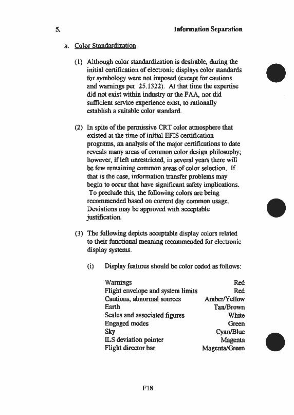
5. Information Separation
a. Color Standardization
(1) Although color standardization is desirable, during the initial certification of electronic displays color standards for symbology were not imposed (except for cautions and warnings per 25.1322). At that time the expertise did not exist within industry or the FAA, nor did sufficient service experience exist, to rationally establish a suitable color standard.
(2) In spite of the permissive CRT color atmosphere that existed at the time of initial EFIS certification programs, an analysis of the major certifications to date reveals many areas of common color design philosophy; however, if left unrestricted, in several years there will be few remaining common areas of color selection. If that is the case, information transfer problems may begin to occur that have significant safety implications. To preclude this, the following colors are being recommended based on current day common usage. Deviations may be approved with acceptable justification.
(3) The following depicts acceptable display colors related to their functional meaning recommended for electronic display systems.
(i) Display features should be color coded as follows:
Warnings Flight envelope and system limits Cautions, abnormal sources Earth Scales and associated figures Engaged modes Sky ILS deviation pointer Flight director bar
Fl8
Red Red
Amber/Yell ow Tan/Brown
White Green
Cyan/Blue Magenta
Magenta/Green
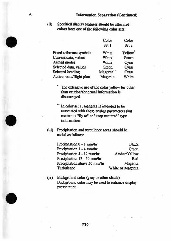
5. Information Separation (Continued)
(ii) Specified display features should be allocated colors from one of the following color sets:
Color Color Set 1 Set 2
Fixed reference symbols White Yellow Current data, values White Green Armed modes White Cyan Selected data, values Green Cyan Selected heading Magenta •• Cyan Active route/flight plan Magenta White
.
The extensive use of the color yellow for other than caution/abnormal information is discouraged.
•• In color set 1, magenta is intended to be associated with those analog parameters that constitute "fly to" or "keep centered" type information.
(iii) Precipitation and turbulence areas should be coded as follows:
Precipitation 0 - 1 mmlhr Precipitation 1 - 4 mmlhr Precipitation 4- 12 mmlhr Precipitation 12- 50 mmlhr Precipitation above 50 mmlhr Turbulence
Black Green
Amber/Yellow Red
Magenta White or Magenta
(iv) Background color (gray or other shade) Background color may be used to enhance display presentation.
Fl9
5. Information Separation (Continued)
( 4) When there is a deviation from any of the above symbol color assignments, the manufacturer should ensure that the chosen color set is not susceptible to confusion or color meaning transference problems due to dissimilarities with this standard. The FAA test pilot should be familiar with other systems in use and evaluate the system specifically for confusion in color meaning.
(5) The FAA does not intend to limit electronic displays to the above colors, although they have been shown to work well. The colors available from a symbol generator/display unit combination should be carefully selected on the basis of their chrominance separation. Research studies indicate that regions of relatively high color confusion exist between red and magenta, magenta and purple, cyan and green, and yellow and orange (amber). Colors should track with brightness so that chrominance and relative chrominance separation are maintained as much as possible over day-night operation. Requiring the flightcrew to discriminate between shades of the same color for symbol meaning in one display is not recommended.
(6) Chrominance uniformity should be in accordance with the guidance provided in SAE Document ARP 1874. As designs are finalized, the manufacturer should review his color selections to ensure the presence of color works to the advantage of separating logical electronic display functions or separation of types of displayed data. Color meanings should be consistent throughout the color CRT displays in the cockpit. In the past, no criteria existed requiring similar color schemes for left and right side installations using electromechanical instruments.
F20

5. Information Separation (Continued)
b. Color Perception vs. Workload
(1) When color displays are used, colors should be selected to minimize display interpretation workload. Symbol coloring should be related to the task or crew operation function. Improper color coding increases response times for display item recognition and selection, and increases the likelihood of errors in situations where response rate demands exceed response accuracy demands. Color assignments that differ from other displays in use, either electromechanical or electronic, or that differ from common usage (such as red, yellow, and green for stoplights), can potentially lead to confusion and information transferal problems.
(2) When symbology is configured such that symbol characterization is not based on color contrast alone, but on shape as well, then the color information is seen to add a desirable degree of redundancy to the displayed information. There are conditions in which pilots whose vision is color deficient can obtain waivers for medical qualifications under Part 61 of the FAR In addition, normal aging of the eye can reduce the ability to sharply focus on red objects, or discriminate blue/green. For pilots with such deficiency, display interpretation workload may be unacceptably increased unless symbology is coded in more dimensions than color alone. Each symbol that needs separation because of the criticality of its information content should be identified by at least two distinctive coding parameters (size, shape, color, location, etc.).
(3) Color diversity should be limited to as few colors as practical, to ensure adequate color contrast between symbols. Color grouping of symbols, annunciations, and flags should follow a logical scheme. The contribution of color to information density should not make the display interpretation times so long that the pilot perceives a cluttered display.
F21
5. Information Separation (Continued)
c. Standard Symbology. Many elements of electronic display formats lend themselves to standardization of symbology, which would shorten training and transition times when pilots change airplane types. At least one industry group (SAE) is working toward identifying these elements and proposing suitable standards. Future revisions of this advisory circular may incorporate the results of such industry efforts.
d. Symbol Position
(1) The position of a message or symbol within a display conveys meaning to the pilot. Without the consistent or repeatable location of a symbol in a specific area of the electronic display, interpretation errors and response times may increase. The following symbols and parameters should be position consistent:
(i) Autopilot and flight director modes of operation.
(ii) All warning/caution/advisory annunciation locations.
(iii) All sensor data: altitude, airspeed, glideslope, etc.
(iv) All sensor failure flags. (Where appropriate, flags should appear in the area where the data is normally placed.)
(v) Either the pointer or scale for analog quantities should be fixed. (Moving scale indicators that have a fixed present value may have variable limit markings.)
F22
5. Information Separation (Continued)
(2) An evaluation of the positions of the different types of alerting messages and annunciations available within the electronic display should be conducted, with particular attention given to differentiation of normal and abnormal indications. There should be no tendency to misinterpret or fail to discern a symbol, alert, or annunciation, due to an abnormal indication being displayed in the position of a normal indication, and having similar shape, size, or color.
(3) Pilot and copilot displays may have minor differences in format, but all such differences should be evaluated specifically to ensure that no potential for interpretation error exists when pilots make cross-side display comparisons.
(4) If the display incorporates slow rate "dithering" to reduce phosphor burn from stationary symbology, the entire display should be moved at a slow rate in order to not change the spatial relationships of the symbology collection as a whole.
F23
5. Information Separation (Continued)
e. Clutter. A clutter display is one which uses an excessive number and/or variety of symbols, colors, or small spatial relationships. This causes increased processing time for display interpretation. One of the goals of display format design is to convey information in a simple fashion in order to reduce display interpretation time. A related issue is the amount of information presented to the pilot. As this increases, tasks become more difficult as secondary information may detract from the interpretation of information necessary for the primary task. A second goal of display format design is to determine what information the pilot actually requires in order to perform the task at hand. This will serve to limit the amount of information that needs to be presented at any point in time. Addition of information by pilot selection may be desirable, particularly in the case of navigational displays, as long as the basic display modes remain uncluttered after pilot deselection of secondary data. Automatic deselection of data has been allowed in the past to enhance the pilot's performance in certain emergency conditions ( deselection of AFCS engaged mode annunciation and flight director in extreme attitudes).
F24
5. Information Separation (Continued)
g. Attention-Getting Requirements
(1) Some electronic display functions are intended to alert the pilot to changes: navigation sensor status changes (VOR flag), computed data status changes (flight director flag or commend cue removal), and flight control system normal mode changes (annunciator changes from armed to engaged) are a few examples. For the displayed information to be effective as an attention-getter, some easily noticeable change must be evident. A legend change by itself is inadequate to annunciate automatic or uncommanded mode changes. Color changes may seem adequate in low light levels or ambient light levels. Motion is an excellent attentiongetting device. Symbol shape changes are also effective, such as placing a box around freshly changed information. Short-term flashing symbols (approximately 10 seconds or flash until acknowledge) are effective attention-getters. A permanent or longterm flashing symbol that is noncancellable should not be used.
(2) In some operations, continued operation with inoperative equipment is allowed (under provisions of an MEL). The display designer should consider the applicant's MEL desires, because in some cases a continuous strong alert may be too distracting for continued dispatch.
h. Color Drive Failure. Following a single color drive failure, the remaining symbology should not present misleading information, although the display does not have to be usable. If the failure is obvious, it may be assumed that the pilot will not be susceptible to misleading information due to partial loss of symbology. To make this assumption valid, special cautions may have to be included in the AFM procedures that point out to the pilot that important information formed from a single primary color may be lost, such as red flags.
F25
6. Display Visual Characteristics
b. Chromaticity and Luminance.
(1) Readability of the displays should be satisfactory in all operating and environmental lighting conditions expected in service. Four light conditions known to be critical for testing are:
(i) Direct sunlight on the display through a side cockpit window (usually short term with conventional window arrangements).
(ii) Sunlight through a front window illuminating white shirts which are reflected in the CRT (a function of the CRT front plate filter).
(iii) Sun above the forward horizon and above a cloud deck in the pilot's eyes (usually a prolonged situation and the most critical of these four).
(iv) Night and/or dark environment. Brightness should be controllable to a dim enough setting such that outside vision is not impaired while maintaining an acceptable presentation.
(2) When displays are evaluated in these critical lighting situations, the display should be adjusted to a brightness level representative of that expected at the end of the CRT's normal useful life (5,000 to 20,000 hours), or adjusted to a brightness level selected by the manufacturer as the minimum acceptable output and measurable by some readily accomplishment maintenance tests. If the former method is used, adequate evaluations should be performed to ensure that the expected end of life brightness levels are met. Some manufacturers have found, and the FAA has accepted, that 50 percent of original brightness level is a realistic end of life value. If the latter method is used, procedures should be established to require periodic inspections, and these limits should then become part of the service life limits of the airplane system.
F26
6. Display Visual Characteristics (Continued)
(3) Large fields used in color displays as background (e.g., blue sky and brown earth for attitude) for primary flight control symbols need not be easily discriminated in these high ambient light levels, provided the proper sense of the flight control information is conveyed with a quick glance.
( 4) Electronic display systems should meet the luminance (photometric brightness) levels of SAE Document ARP 1874. A system designed to meet these standards should be readily visible in all the lighting conditions listed in paragraphs 6b(l) and 6b(2), and should not require specific flight testing for luminance if the system has been previously installed in another airplane with similar cockpit window arrangements. If the display evaluation team feels that some attributes are marginal under extreme lighting conditions, the following guidelines may be used:
(i) The symbols that convey quick-glance attitude and flight path control information (e.g., horizon line, pitch scale, fixed airplane symbol and/or flight path symbol, sky pointer and bank indices, flight director bars) should each have adequate brightness contrast with its respective background to allow it to be easily and clearly discernible.
(ii) The combination of color and brightness of any subset of these symbols which may, due to relative motion of a dynamic display, move adjacent to each other and use color as an aid for symbol separation (e.g., flight director bars and fixed airplane symbol), should render each symbol distinctly identifiable in the worst case juxtaposition.
F27
6. Display Visual Characteristics (Continued)
(iii) Flags and annunciations that may relate to events of a time critical nature (including warnings and cautions defined in paragraph 10 of this AC, as well as flight control system annunciations of mode reversions) should have a sufficient contrast with their background and immediate environment to achieve an adequate level of attensity (attention getting properties). Color discrimination in high brightness ambient levels may not be necessary if the symbol remains unambiguous and clearly distinct from adjacent normal state or alphanumeric characters.
(iv) Analog scale displays (heading, air data, engine data, CDis, or course lines) should each have adequate brightness with its respective background to allow it to be easily and clearly discernible. Colored warning and caution markings on scales should retain color discrimination. Symbols used as targets and present value pointers in juxtaposition to a scale should remain distinct. If color is required to convey the meaning of similar shaped targets or indices, the color should remain easily discernible.
(v) Flags and annunciations should still be visible at low display brightness when the display is adjusted to the lowest usable level for flight with normal symbology (day or night).
(vi) Raster fields conveying information such as weather radar displays should allow the raster to be independently adjustable in luminance from overlaid stroke symbology. The range of luminance control should allow detection of color difference between adjacent small raster areas no larger than 5 milliradians in principal dimension; while at this setting, overlying map symbology, if present, should be discernible.
F28
6. Display Visual Characteristics (Continued)
(5) Automatic brightness adjustment systems can be employed to decrease pilot workload and increase tube lifetime. Operation of these systems should be satisfactory over a wide range of ambient light conditions including the extreme cases of a forward low sun and a quartering rearward sun shining directly on the display. A measure of manual adjustment should be retained to provide for normal and abnormal operating differences. In the past it has been found that sensor location and field of view may be as significant as the tube brightness dynamics. Glareshield geometry and window location should be considered in the evaluation.
F29/F30


APPENDIXFJ
FAA-TIA-ST0346WI-A
Type Inspection Authorization
F31
18B. The Flight Test Pilot/Engineer are requested to:
c) Evaluate steering response while the autopilot is coupled to the GPS during a variety of different track and mode changes. This evaluation should include transition from en route to approach transition to approach modes and vice-versa. All available display sensitivities shall be evaluated.
f) Verify satisfactory electromagnetic compatibility between the GPS installation and other onboard equipment (can be partially accomplished as a ground test). Demonstrate satisfactory isolation from harmonic interference of VHF communication transceivers by tuning each VHF transmitter to the frequencies listed below for a period of 20 seconds while observing the signal status of each satellite being received. Degradation of individually received satellite signals below a point where navigation is no longer possible is not acceptable. This evaluation should be accomplished in each operating mode.
121.150 MHz 121.175 MHz 121.200 MHz
131.250 MHz 131.275 MHz 131.300 MHz
NOTE: Reevaluation of installed VHF transceiver performance is not necessary if the filter insertion loss is 2 dB or less.
h) Evaluate visibility of all controls, displays, and annunciators relating to the GPS 155 installation during day and night lighting conditions. No distracting cockpit glare or reflections may be introduced and all controls must be illuminated for identification and ease of use. Night lighting shall be consistent with other cockpit lighting.
i) Conduct an analysis of crew workload when operating the GPS 155 system in association with other piloting requirements. This evaluation should include all operating modes, transition between modes, instrument approaches, en route operations, accomplishment of SIDs and STARs, etc. The pilot workload subjective evaluation forms attached to this TIA should be used to complete this evaluation.
F32
18B. The Flight Test Pilot/Engineer are requested to: (Continued)
j) Validate GPS 155 accuracy in each operating mode by conducting at least 5low altitude passes (<100ft AGL) over one or more surveyed locations (survey location data must be in either the WGS-84 or NAD-83 coordinate datum). The displayed GPS 155 position shall be recorded when the aircraft crosses the designated location and compared to the known location coordinates. System accuracy is the difference between the coordinate position detennined by the GPS 155 and the coordinate position of the surveyed location. Accuracy requirements are 0; 124 nm in the en route and tenninal modes and 0.056 nm in the approach mode.
k) Verify continuity of navigation data during normal aircraft maneuvering, including holding patterns and turns at up to at least 30 degrees of bank for one minute.
1) Verify that flight technical error (FTE) can be maintained at less than 1.0 nm for en route, 1.0 nm for approach transition, and 0.25 nm for approach operating modes both with and without autopilot use.
m) Conduct a sufficient number of approaches and transitions from en route to tenninal to approach operations using the navigation system in the approach environment. A variety of approach geometries and general arrangements should be used. Operations should include air traffic vectoring and pilot navigation. This evaluation should include at least:
( 1) Turn anticipation (2) Waypoint sequencing (3) Display sensitivity changes (4) Annunciations (5) Procedure turns at the final approach fix (FAF) (6) Holding patterns at the missed approach holding fix (7) Transitions from TO-FROM operation to TO-TO operation (8) Heading legs after the initial approach fix (IAF) to intercept
the final approach course both before and after the F AF (9) DIRECT TO operation before and after the IAF
F33/F34


APPENDIXMl
MILITARY STANDARD 1472D
Human Engineering Design Criteria For Military Systems, Equipment And Facilities
Ml

5.1 ControVDisplay Integration
5.1.1.1 Relationship
The relationships of a control to its associated display and the display to the control shall be immediately apparent and unambiguous to the operator. Controls should be located adjacent to (normally under or to the right of) their associated displays and positioned so that neither the control nor the hand normally used for setting the control will obscure the display.
5.1.1.2 Design
Control-display relationships shall be apparent through proximity, similarity of groupings, coding, framing, labeling, and similar techniques.
5.1.2.1 Functional Grouping
Functionally related controls and displays shall be located in proximity to one another--arranged in functional groups (e.g., power, status, test).
5.1.2.1.1 Functional Group Arrangement
5.1.2.1.1.1 Sequence
Functional groups of controls and displays shall be located to provide for left-to-right (preferred) or top-to-bottom order of use, or both.
5.1.2.1.1.2 Access
Providing that the integrity of grouping by function and sequence is not compromised, the more frequently used groups and the most important groups should be located in areas of easiest access. Control-display groups required solely for maintenance purposes shall be located in positions providing a lesser degree of access relative to operating groups.
M2

5.1.2.1.1.3 Functional Group Marking
Functional groups may be set apart by outlining with contrasting lines which completely encompass the groups. Where such coding is specified by the procuring activity, and where gray panels are used, noncritical functional groups (i.e., those not associated with emergency operations) shall be outlined with a 1.5 mm (1116 in) black border (27038 ofFED-STD-595), and those involving emergency or extremely critical operations shall be outlined with a 5 mm (3/16 in) red border (21136 ofFED-STD-595). As an alternate method, contrasting color pads or patches may be used to designate both critical and noncritical functional areas, subject to prior approval by the procuring activity. When red compartment lighting is used, an orange-yellow (23538 ofFED-STD-595) and black (27038 ofFED-STD-595) striped border shall be used to outline functional groups involving emergency or extremely critical operations. Control-display areas in aircraft crew stations shall be delineated in accordance with MIL-M-18012.
5.1.2.1.1.4 Consistency
Location of recurring functional groups and individual items shall be similar from panel to panel. Mirror image arrangements shall not be used.
5.1.2.3 Arrangement Within Groups
Controls and displays within functional groups shall be located according to operational sequence or function, or both.
5.2 Visual Displays
5.2.1.1 Display IDumination
When the degree of dark adaptation required is not maximum, low brightness white light (preferably integral), adjustable as appropriate, shall be used; however, when complete dark adaptation is required, low luminance (0.07-0.34 cd/m2
) red light (greater than 620 nm) shall be provided.
M3
5.2.1.2 Light Distribution
Where multiple displays are grouped together, the displays shall appear of equal brightness across the range of full ON to full OFF. Light distribution for integrally illuminated instruments shall be sufficiently uniform such that the ratio of standard deviation of indicator element luminances to mean indicator luminance shall not be more than 0.25, using eight or more equally spaced test measurements.
5.2.1.4.4 Reflection
Displays shall be constructed, arranged, and mounted to prevent reduction of information transfer due to the reflection of the ambient illumination from the display cover. Reflection of instruments and consoles in windshields and other enclosures shall be avoided. If necessary, techniques (such as shields and filters) shall be employed to insure that system performance will not be degraded.
5.2.2 Transilluminated Displays
5.2.2.1.9 Luminance
The luminance of transilluminated displays shall be compatible with the expected ambient illuminance level, and shall be at least 10% greater than the surrounding luminance. Where glare must be reduced, the luminance of transilluminated displays should not exceed 300% of the surrounding luminance.
5.2.2.1.10 Luminance Control
When displays will be used under varied ambient illuminance, a dimming control shall be provided. The range of the control shall permit the displays to be legible under all expected ambient illuminance. The control shall be capable of providing multiple step or continuously variable illumination. Dimming to full OFF may be provided in non-critical operations, but shall not be used if inadvertent failure to turn on an indicator could lead to critical operator failures (i.e., failure to detect or perform a critical step in an operation).
M4

5.2.2.1.11 False Indication or Obscuration Provision shall be made to prevent direct or reflected light from making indicators appear illuminated when they are not, or to appear extinguished when they are illuminated. Self-reflection shall be minimized by proper orientation of the display with respect to the observer.
5.2.2.1.12 Contrast Within the Indicator
The luminance contrast (see 3.17) within the indicator shall be at least 50%. This 50% luminance contrast requirement does not apply to special displays specifically designed for legibility in sunlight or where legibility is obtained through color contrast (and other techniques) rather than luminance contrast. For low ambient illumination applications (e.g., MIL-L-25467), this ratio should be at least 90% (see 3 .17), with the background luminance less than the figure luminance.
5.2.2.1.18 Color Coding
With the exception of aircrew station signals which shall conform to MIL-STD-411, and training equipment which shall conform to MIL-T-23991, transilluminated displays shall conform to the following color coding scheme, in accordance with Type I -Aviation colors ofMIL-C-25050.
a. RED shall be used to alert an operator that the system or any portion of the system is inoperative, or that a successful mission is not possible until appropriate corrective or override action is taken. Examples of indicators which should be coded RED are those which display such information as "no-go", "error", "failure", "malfunction", etc.
b. FLASHING RED shall be used only to denote emergency conditions which require operator action to be taken without undue delay, or to avert impending personnel injury, equipment damage, or both.
c. YELLOW shall be used to advise an operator that a condition exists which is marginal. YELLOW shall also be used to alert the operator to situations where caution, recheck, or unexpected delay is necessary.
M5
5.2.2.1.18
5.2.2.1.19
Color Coding (Continued)
d. GREEN shall be used to indicate that the monitored equipment is in tolerance or a condition is satisfactory and that it is all right to proceed (e.g., "goahead", "in-tolerance", "ready", "function activated").
e. WlflTE shall be use to indicate system conditions that do not have "right" or "wrong" implications, such as alternative functions (e.g., Missile No. 1 selected for launch, etc.) or transitory conditions (e.g., action or test in progress, function available), provided such indication does not imply success or failure of operations.
f. BLUE may be used for an advisory light, but preferential use of BLUE should be avoided.
Flashing Lights
The use of flashing lights shall be minimized. Flashing lights should be used only when it is necessary to call the operator's attention to some condition requiring immediate action. The flash rate shall be within 3 to 5 flashes per second with approximately equal amounts of ON and OFF time. Flashing lights which could be simultaneously active should have synchronized flashes. If the indicator is energized and the flasher device fails, the light shall illuminate and burn steadily (see 5.3 .2.4).
5.2.2.2.3 Positive vs. Negative Legend
When the operator's dark adaptation must be maintained, or where legibility in high ambient illumination is critical, illumination label/opaque background format shall be used and illuminated background/opaque label format shall be used only for critical alerting indicators (e.g., master warning lights). Where operator dark adaptation is not required, illuminated background/opaque label format should be used; contrast reversal may be employed under these conditions to designate displays which have physical appearance similar to legend switches on the same panel.
M6

~.2.2.2.~ Visibility and Legibility
In other than aircrew stations, and with the exception of warning and caution indicators, the lettering on single-legend indicators shall be visible and legible whether or not the indicator is energized.
~.2.4 Cathod Ray Tube (CRT) Displays
~.2.4.1 Signal Size
When a target of complex shape is to be distinguished from a nontarget shape that is also complex, the target signal should subtend not less than 6 mrad (20 minutes) of visual angle and should subtend not less than 10 lines or resolution elements. Image quality shall be consistent with the operator's needs.
~.2.4.2 Viewing Distance
A 400 mm (16 in) viewing distance shall be provided whenever practicable. When periods of scope observation will be short, or when dim signals must be detected, the viewing distance may be reduced to 250 mm (10 in). Design should permit the observer to view the scope from as close as desired. Displays which must be placed at viewing distances greater than 400 mm (16 in) due to other considerations shall be appropriately modified in aspects such as display size, symbol size, brightness ranges, line-pair spacing, and resolution.
5.2.4.3 Screen Luminance
The ambient illuminance shall not contribute more than 25% of screen brightness through diffuse reflection and phosphor excitation. A control shall be provided to vary the CRT luminance from 10% of minimum ambient luminance to full CRT luminance. A control shall be provided to vary the luminous symbol/dark background or dark symbol/luminous background contrast ratio. Contrast adjustment shall not be included in flight deck displays because they are disallowed by FAA regulation.
M7
5.2.4.5 Luminance Range of Adjacent Surfaces
The luminance range of surfaces immediately adjacent to scopes shall be between 10% and 100% of screen background luminance. With the exception of emergency indicators, no light source in the immediate surrounding area shall be of a greater luminance than the CRT signal.
5.2.4.6 Ambient Dluminance
The ambient illuminance in the CRT area shall be appropriate for other visual functions (e.g., setting controls, reading instruments, maintenance) but shall not interfere with the visibility of signals on the CRT display. When a CRT display is used in variable ambient illuminance, illuminance controls shall be provided to dim all light sources, including illuminated panels, indicators and switches in the immediate surround. Automatic adjustment of CRT brightness may be used if the CRT brightness is automatically adjusted as a function of ambient illuminance and the range of automatic adjustment is adequate for the full range of ambient illuminance.
5.2.4.7 Reflected Glare
Reflected glare shall be minimized by proper placement of the scope relative to the light source, use of a hood or shield, or optical coatings on the CRT or filter control over the light source.
5.2.6 Other Displays
5.2.6.8.3 Symbol Definition
The smallest definition for a dot matrix shall be 5 by 7 dots, with 7 by 9 preferred. If system requirements call for symbol rotation, a minimum of 8 by 11 is required, with 15 by 21 preferred.
5.2.6.8.4 Alphanumeric Character and Symbol Sizes
Alphanumeric and symbolic characters shall not subtend less than 4.7 mrad (16 min) of visual angle. Flight display characters, which must be read under aircraft environmental conditions, shall not subtend less than 7 mrad (24 min) of visual angle.
M8
5.2.6.8.5 Use of Upper Case
Alphanumeric characters shall be upper case.
5.2.6.8.6 Viewing Angle
The optimum viewing angle is perpendicular to the display. Dot matrix or segmented displays should not be presented for viewing at an angle larger than 610 mrad (35°) off axis.
5.2.6.8.7 Emitter Color
Monochromatic displays shall use the following colors in order of preference: green (555nm), yellow (575nm), orange (585nm), and red (660nm). Blue emitters should be avoided.
5.2.6.8.8 Intensity Control
Dimming controls shall be provided where applicable to maintain appropriate legibility and operator dark adaptation level.
5.3 Audio Displays
5.3.2.2.2 Single Element Signal
When reaction time is critical, signals shall be of short duration. If a single element signal is permissible, all essential information shall be transmitted in the first 0.5 second.
5.3.2.3 Caution Signals
Caution signals shall be readily distinguishable from warning signals and shall be used to indicate conditions requiring awareness, but not necessarily immediate action.
M9

5.3.3.1 Frequency
5.3.3.1.1 Range
The frequency range shall be between 200 and 5,000 Hz and, if possible, between 500 and 3,000 Hz. When signals must travel over 300m (985ft), sounds with frequencies below 1,000 Hz should be used. Frequencies below 500 Hz should be used when signals must bend around obstacles or pass through partitions. The selected frequency band shall differ from the most intense background frequencies and shall be in accordance with other criteria in this section.
5.3.3.1.2 Spurious Signals
The frequency of a warning tone shall be different from that of the electric power employed in the system, to preclude the possibility that a minor equipment failure may generate a spurious signal.
5.3.3.2.2.3 Discomfort
Audio warning signals should not be of such intensity as to cause discomfort or "ringing" in the ears as an after-effect.
5.3.4.1 Audibility
A signal-to-noise ratio of at least 20 dB shall be provided in at least one octave band between 200 and 5,000 Hz at the operating position of the intended receiver.
5.3.4.2.4 Headset
When the operator is wearing earphones covering both ears during normal equipment operation, the audio warning signal shall be directed to the operator's headset as well as to the work area. Binaural headsets should not be used in any operational environment below 85 dB (A) when that environment may contain sounds that provide the operator with useful information when that information cannot be directed to the operator's headset. Such sounds may include voices, machine noise that indicates wear or malfunction, and other auditory indications of system performance/mission status.
MlO
5.3.4.3 Discriminability
5.3.4.3.1 Use of Different Characteristics
When several different audio signals are to be used to alert an operator to different types of conditions, discriminable difference in intensity pitch or use of beats and harmonics shall be provided. If absolute discrimination is required, the number of signals to be identified shall not exceed four.
5.3.4.3.2 Coding
Where discrimination of warning signals from each other will be critical to personnel safety or system performance, audio signals shall be appropriately coded. Alarms that are perceptibly different shall correlate with different conditions requiring critically different operator responses (e.g., maintenance, emergency conditions, and health hazards). Such signals shall be sufficiently different to minimize the operator's search of visual displays.
5.3.4.3.5 Differentiation from Routine Signals
Audio alarms intended to bring the operator's attention to a malfunction or failure shall be differentiated from routine signals, such as bells, buzzers, and normal operation noises.
5.3.4.3.6 Prohibited Types of Signals
The following types of signals shall not be used as warning devices where possible confusion might exist because of the operational environment
a. Modulated or interrupted tones that resemble navigation signals or coded radio transmissions.
b. Steady signals that resemble hisses, static, or sporadic radio signals.
c. Trains of impulses that resemble electrical interference whether regularly or irregularly spaced in time.
d. Simple watbles which may be confused with the type made by two carriers when one is being shifted in frequency (beat -frequency-oscillator effect).
Mll
5.3.4.3.6
5.3.4.5
5.3.4.5.1
Prohibited Types of Signals (Continued)
e. Scramble speech effects that may be confused with cross modulation signals from adjacent channels.
f. Signals that resemble random noise, periodic pulses, steady or frequency modulated simple tones, or any other signals generated by standard countermeasure devices (e.g., "bagpipes").
g. Signals similar to random noise generated by air conditioning or any other equipment.
Masking
Other Critical Channels
Audio warning signals shall not interfere with any other critical functions or warning signals, or mask any other critical audio signals.
5.3.5.2 Intensity
Verbal alarms for critical functions shall be at least 20 dB above the speech interference level at the operating position of the intended receiver.
5.3.5.3.1 Type of Voice
The voice used in recording verbal warning signals shall be distinctive and mature.
5.3.5.4 Speech Processing
Verbal warning signals shall be processed only when necessary to increase or preserve intelligibility, such as by increasing the strength of consonant sounds relative to vowel strength. Where a signal must be relatively intense because of high ambient noise, peak-clipping (see 3.24) may be used to protect the listener against auditory overload.
M12
5.3.5.5 Message Content
In selecting words to be used in audio warning signals, priority shall be given to intelligibility, aptness, and conciseness in that order.
5.3.5.6.1 Critical Warning Signals
Critical warning signals shall be repeated with not more than a 3-second pause between messages until the condition is corrected or overridden by the crew.
5.3.6.1 Automatic or Manual Shut-Off
When an audio signal is designed to persist as long as it contributes useful information, a shut-off switch controllable by the operator, the sensing mechanism, or both, shall be provided, depending on the operational situation and personnel safety factors.
5.3.6.5 Duration
Audio warning signal duration shall be at least 0.5 second, and may continue until the appropriate response is made. Completion of a corrective action by the operator or by other means shall automatically terminate the signal.
5.3.12 Speech Intelligibility
5.3.12.1 General
When information concerning the speech intelligibility of a system is required, three recommended methods are available, with the appropriate selection being dependent upon the requirements of the test.
a. The ANSI standard method of measurement of phonetically balanced (PB) monosyllabic word intelligibility, S3.2-1960, should be used when a high degree of test sensitivity and accuracy is required.
Ml3
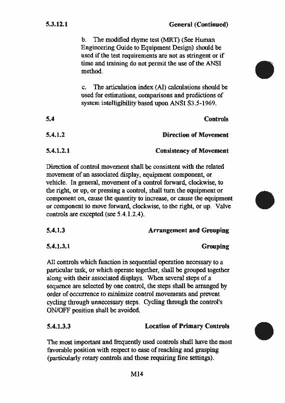
5.3.12.1
5.4
5.4.1.2
5.4.1.2.1
General (Continued)
b. The modified rhyme test (MR.T) (See Human Engineering Guide to Equipment Design) should be used if the test requirements are not as stringent or if time and training do not permit the use of the ANSI method.
c. The articulation index (AI) calculations should be used for estimations, comparisons and predictions of system intelligibility based upon ANSI S3.5-1969.
Controls
Direction of Movement
Consistency of Movement
Direction of control movement shall be consistent with the related movement of an associated display, equipment component, or vehicle. In general, movement of a control forward, clockwise, to the right, or up, or pressing a control, shall turn the equipment or component on, cause the quantity to increase, or cause the equipment or component to move forward, clockwise, to the right, or up. Valve controls are excepted (see 5.4.1.2.4).
5.4.1.3 Arrangement and Grouping
5.4.1.3.1 Grouping
All controls which function in sequential operation necessary to a particular task, or which operate together, shall be grouped together along with their associated displays. When several steps of a sequence are selected by one control, the steps shall be arranged by order of occurrence to minimize control movements and prevent cycling through unnecessary steps. Cycling through the control's ON/OFF position shall be avoided.
5.4.1.3.3 Location of Primary Controls
The most important and frequently used controls shall have the most favorable position with respect to ease of reaching and grasping (particularly rotary controls and those requiring fine settings).
Ml4

5.4.1.3.4 Consistency
The arrangement of functionally similar, or identical, primary controls shall be consistent from panel to panel throughout the system, equipment, or vehicle (e.g., a movement of a control to the right or left should result in a corresponding movement of a display element to the right or left).
5.4.1.4 Coding
5.4.1.4.1 Methods and Requirements
The use of a coding mode (e.g., size and color) for a particular application shall be governed by the relative advantages and disadvantages of each type of coding. Where coding is used to differentiate among controls, application of the code shall be uniform throughout the system. (See Table VIII for advantages and disadvantages).
5.4.1.4.3 Size Coding
No more than three different size of controls shall be used in coding controls for discrimination by absolute size. Controls used for performing the same function on different items of equipment shall be the same size. When knob diameter is used as the coding parameter, differences between diameters shall not be less than 13 mm (0.5"). When knob thickness is the coding parameter, differences between thickness shall not be less than 10 mm (0.4").
M15
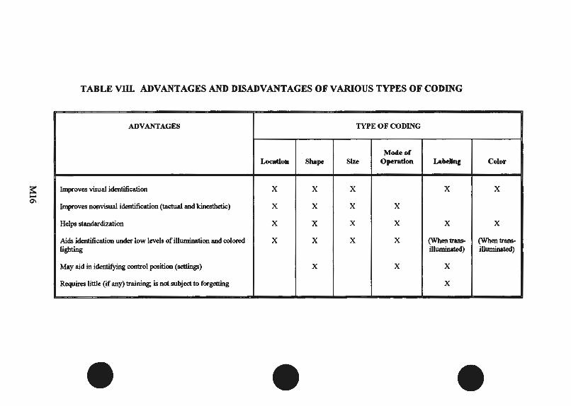
TABLE VIII. ADVANTAGES AND DISADVANTAGES OF V ARlO US TYPES OF CODING
ADVANTAGES TYPE OF CODING
Mocleor Location Shape Size Operation LabellnJ Color
s:: Improves visual identification X X X X X .... 0\
Improves nonvisual identification (tactual and kinesthetic) X X X X
Helps standardization X X X X X X
Aids identification under low levels of illumination and colored X X X X (When trans- (When trans-lighting illuminated) illuminated)
May aid in identifYing control position(~) X X X
Requires little (if any) training; is not subject to forgetting X
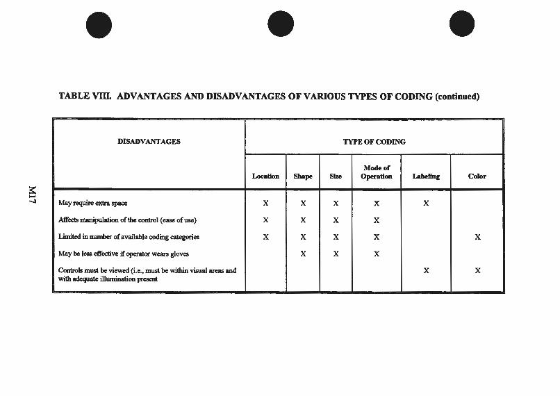
TABLE VIII. ADVANTAGES AND DISADVANTAGES OF V ARlO US TYPES OF CODING (continued)
DISADVANTAGES TYPE OF CODING
-Mode of
Location Shape Size Operation Labellnc Color
a: .... -..l May require extra space X X X X X
I
Affects manipulation ofthe control (ease of use) X X X X '
Limited in nwnber of available coding categories X X X X X
May be less effective if operator wears gloves X X X
Controls must be viewed (i.e., must be within visual areas and X X with adequate illumination present
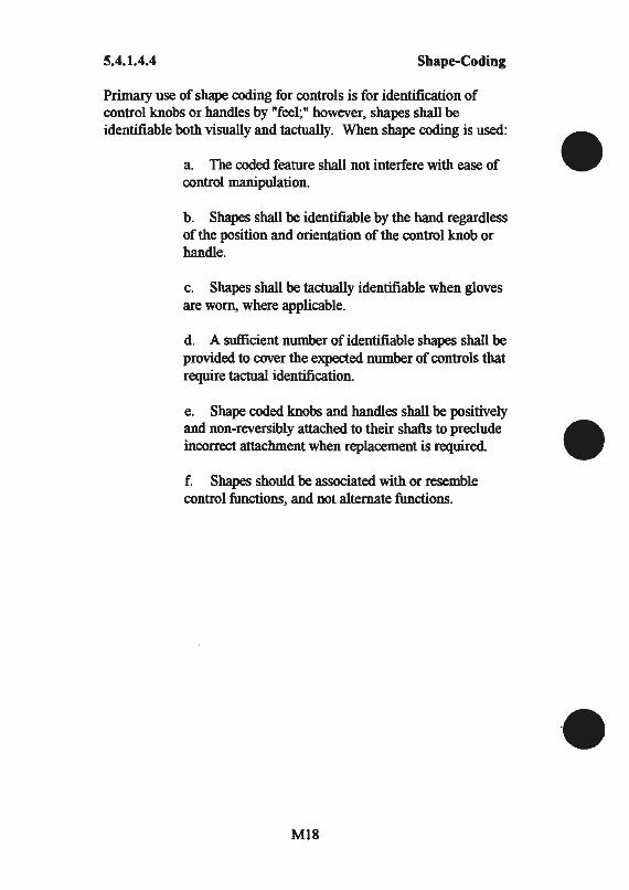
5.4.1.4.4 Shape-Coding
Primary use of shape coding for controls is for identification of control knobs or handles by "feel;" however, shapes shall be identifiable both visually and tactually. When shape coding is used:
a. The coded feature shall not interfere with ease of control manipulation.
b . Shapes shall be identifiable by the hand regardless of the position and orientation of the control knob or handle.
c. Shapes shall be tactually identifiable when gloves are worn, where applicable.
d. A sufficient number of identifiable shapes shall be provided to cover the expected number of controls that require tactual identification.
e. Shape coded knobs and handles shall be positively and non-reversibly attached to their shafts to preclude incorrect attachment when replacement is required.
f. Shapes should be associated with or resemble control functions, and not alternate functions.
MIS
5.4.1.4.5 Color-Coding
5.4.1.4.5.1 Choice of Colors
Controls shall be black (17038, 27038 or 37038) or gray (26231 or 36231 ). If color coding is required, only the following colors identified in FED-STD-595 shall be selected for control coding.
5.4.1.4.5.2
a. Red, 11105, 21105, 31105
b. Green, 14187
c. Orange-Yellow, 13538, 23538, 33538
d. White, 17875, 27875, 37875
e. Blue, 15123 shall be used if an additional color is absolutely necessary.
Immediate Action Controls
Color coding of immediate action controls for aircraft shall conform to MIL-M-18012.
5.4.1.4.5.3 Relation to Display
When color-coding must be used to relate a control to its corresponding display, the same color shall be used for both the control and the display.
5.4.1.4.5.4 Control Panel Contrast
The color of the control shall provide contrast between the panel background and the control.
M19
5.4.1.4.5.5 Ambient Lighting and Color-Coding Exclusion
Color coding shall be compatible with anticipated ambient lighting throughout the mission. Color-coding shall not be used as a primaiy identification medium if the spectral characteristics of ambient light during the mission, or the operator's adaptation to that light, varies as the result of such factors as solar glare, filtration of light, and variation from natural to artificial light. If red lighting is to be used during a portion of the mission, controls which would otherwise be coded red shall be coded by orange-yellow and black striping.
5.4.1.8 Prevention of Accidental Actuation
5.4.1.8.1 Location and Design
Controls shall be designed and located so that they are not susceptible to being moved accidentally, particularly critical controls whose inadvertent operation might cause damage to equipment, injury to personnel or degradation of system functions.
5.4.1.8.3 Rapid Operation
Any method of protecting a control from inadvertent operation shall not preclude operation within the time required.
5.4.1.8.4 Methods
For situations in which controls must be protected from accidental actuation, one or more of the following methods, as applicable, shall be used:
a. Locate and orient the controls so that the operator is not likely to strike or move them accidentally in the normal sequence of control movements.
b. Recess, shield, or otherwise surround the controls by physical barriers. The control shall be entirely contained within the envelope described by the recess or barrier.
c. Cover or guard the controls. Safety or lock wire shall not be used.
M20
5.4.1.8.4
5.4.2
5.4.2.1
5.4.2.2.1.2
Methods (Continued)
d. Provide the controls with interlocks so that extra movement (e.g., a side movement out of a detent position or a pull-to-engage clutch) or the prior operation of a related or locking control is required.
e. Provide the controls with resistance (i.e., viscous or coulomb friction, spring-loading, or inertia) so that definite or sustained effort is required for actuation.
f. Provide the controls with a lock to prevent the control from passing through a position without delay when strict sequential activation is necessary (i.e., the control moved only to the next position, then delayed).
g. Design the controls for operation by rotary action.
Rotary Controls
Discrete Rotary Controls
Dimensions, Torque and Separation
The dimensions of knobs shall be within the limits specified in Figure 7. Within these ranges, knob size is relatively unimportant, provided the resistance is low and the knob can be easily grasped and manipulated. When panel space is extremely limited, knobs should approximate the minimum values and should have resistance as low as possible without permitting the setting to be changed by vibration or merely touching the control. Resistance and separation between adjacent edges of knobs shall conform to Figure 7.
5.4.2.2.2 Ganged Control Knobs
5.4.2.2.2.1 Application
Ganged knob assemblies may be used in limited applications when panel space is at a premium. Two-knob assemblies are preferred. Three-knob configurations should be avoided. Ganged knob configurations should not be used under the following conditions:
M21
5.4.2.2.2.1
5.4.2.2.2.2
Application (Continued)
a. Extremely accurate or rapid operations are required.
b. Frequent changes are necessary.
c. Heavy gloves must be worn by the operator.
d. Equipment is exposed to the weather or used under field conditions.
Dimensions and Separation
Dimensions and separation should conform to Figure 8.
5.4.2.2.2.3 Resistance
Resistance shall conform to requirements in Figure 8. Knobs should be serrated. Fine serrations should be used on precise adjustment knobs; coarse serrations should be used on gross adjustment knobs.
5.4.2.2.2.4 Marking
An indexing mark or pointer shall be provided on each knob. Marks or pointers should differ sufficiently to make it apparent which knob indexing mark is being observed.
5.4.2.2.2.5 Knob/Display Relationship
When each knob of a ganged assembly must be related to an array of visual displays, the knob closest to the panel shall relate to the leftmost display in a horizontal array, or the uppermost display in a vertical array (see Figure 8).
M22
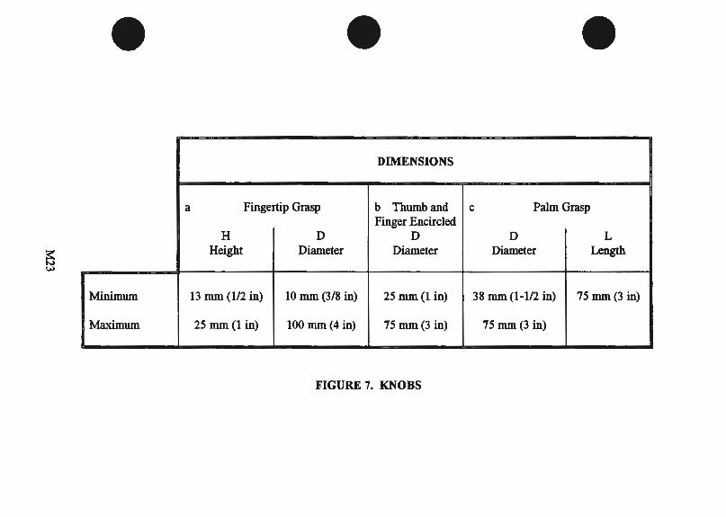
DIMENSIONS
a Fingertip Grasp b Thumb and c Palm Grasp Finger Encircled
H D D D L
~ Height Diameter Diameter Diameter Length
w
Minimum 13 mm (1/2 in) 10 mm (3/8 in) 25 mm(1 in) 38 mm (1-112 in) 75 mm(3 in)
Maximum 25 mm (1 in) 100 mm (4 in) 75 mm (3 in) 75 mm(3 in)
--- - --- - -~
FIGURE 7. KNOBS
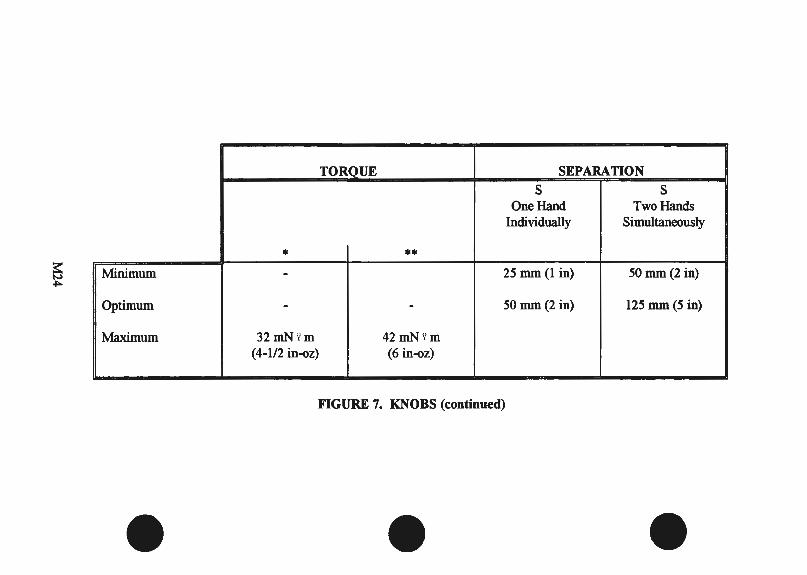
TORQUE SEPARATION
s s One Hand Two Hands
Individually Simultaneously
• •• ~ Minimum - 25 mm(l in) 50 mm(2 in) ~
Optimum - - 50 mm (2 in) 125 mm(5 in)
Maximum 32mNY.m 42mN Y. m (4-l/2 in-oz) (6 in-oz)
-- - - ------ L__ ------ · - -- · --·-
FIGURE 7. KNOBS (continued)
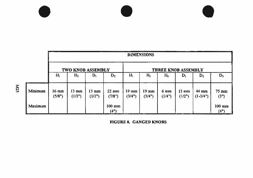
DIMENSIONS
TWO KNOB ASSEMBLY THREE KNOB ASSEMBLY HI H2 01 02 HI H2 H3 01 02 03
~ v. Minimum 16mm 13mm 13mm 22mm 19mm 19mm 6mm 13mm 44mm 75mm (5/8") (112") (1/2") (7/8") (3/4") (3/4") (1/4") (1/2") (1-3/4") (3")
Maximum 100mm 100mm (4") (4")
FIGURE 8. GANGED KNOBS
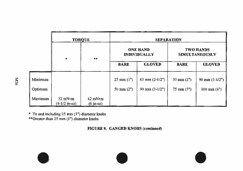
~ 01
TORQUE
* **
Minimum
Optimum
Maximum 32 mNtm 42 mNtm (4-1/2 in-oz) (6 in-oz)
* To and including 25 mm (1 ") diameter knobs **Greater than 25 mm (1 ") diameter knobs
- - --
SEPARATION
ONE HAND TWO HANDS INDIVIDUALLY SIMULTANEOUSLY
BARE GLOVED BARE GLOVED
25 mm (1") 63 mm (2-1/2") 50 mm (2") 90 mm (3-1/2")
50 mm (2") 90 mm (3-1/2") 75 mm (3") 100 mm (4")
'
FIGURE 8. GANGED KNOBS (continued)
5.4.2.2.2.6 Inadvertent Operation
When it is critical to prevent inadvertent activation of one knob as the other is being adjusted, a secondary knob control movement shall be required (e.g., pressing the top knob before it can be engaged with its control shaft). Where inadvertent movement is undesirable but not necessarily critical, knob diameter/depth relationships should be optimized as shown in Figure 8. Contrasting colors between knobs may also be used to improve individual knob identification.
5.4.3 Linear Control
5.4.3.1.1 Push Buttons (Finger or Hand Operated)
5.4.3.1.1.1 Use
Push buttons should be used when a control or an array of controls is needed for momentary contact or for activating a locking circuit, particularly in high-frequency-of-use situations. Push buttons should not be used for discrete control where the functions status is determined exclusively by position of the switch (i.e., an on-off push button that is pressed in and retained to turn a circuit on and pressed again to release the push button and turn the circuit off).
5.4.3.1.1.2 Shape
The push button surface should normally be concave (indented) to fit the finger. When this is impractical, the surface shall provide a high degree of frictional resistance to prevent slipping.
5.4.3.1.1.3 Positive Indication
A positive indication of control actuation shall be provided (e.g., snap feel, audible click, or integral light).
5.4.3.1.1.4 Channel or Cover Guard
A channel or cover guard shall be provided when it is imperative to prevent accidental actuation of the controls. When a cover guard is in the open position, it shall not interfere with operation of the protected device or adjacent controls.
M27
5.4.3.1.1.5 Dimensions, Resistance, Displacement, and Separation
Except for use of push buttons in keyboards, control dimensions, resistance, displacement, and separation between adjacent edges of finger or hand-Qperated push buttons shall conform to the criteria in Figures 11A and 11B.
5.4.3.1.1.6 Interlocks or Barriers
Mechanical interlocks or barriers may be used instead of the spacing required by Figure 11.
5.4.3.1.3 Keyboards
5.4.3.1.3.1 Use
Arrangements of push buttons in the form of keyboards should be used when alphabetic, numeric or special function information is to be entered into a system.
5.4.3.1.3.2 Layout and Configuration
The key configuration and the number of keys are dependent upon the predominant type of information to be entered into the system. The major forms that keyboards can take, which aid in the entry of such information, are given below:
a. Numeric Keyboard: The configuration of a keyboard used to enter solely numeric information should be a 3 x 3 + 1 matrix with the zero digit centered on the bottom row.
5.4.3.1.3.3 Dimension, Resistance, Displacement, and Separation
The control dimensions, resistance, displacement, and separation between adjacent edges of the push buttons which form keyboards shall conform to the criteria in Table 10. For a given keyboard these criteria shall be uniform for all individual keys. For those applications where operation while wearing (trigger fiilger) arctic mittens is required, the minimum key size shall be 19 mm (0.76 in). Other parameters are unchanged from those of bare-handed operation (see Table 10).
M28

DIMENSIONS RESISTANCE
DIAMETER D
Fingertip Thumb or Single Finger Different Thumb or Palm Fingers Palm
~Minimum 9.5 mm (3/8 in) 19 mm (3/4 in) 2.8 N (10 oz) 1.4 N (5 oz) 2.8 N (10 ,OZ)
Maximum 25 mm(l in) 19 mm 0/~_irt) _ __ l)_]'I{40 oz) 5.6 N (2Q_o~) _ 23 N (80 oz)
~ \0
DISPLACEMENT
A Fingertip Thumb or Palm I Minimum 2 mm (5/64 in) 3 mm (1/8 in)
Maximum 6 mm (1/4 in) 38 mm (1-112 in)
FIGURE llA. PUSH BUTTONS (FINGER OR HAND OPERATED)
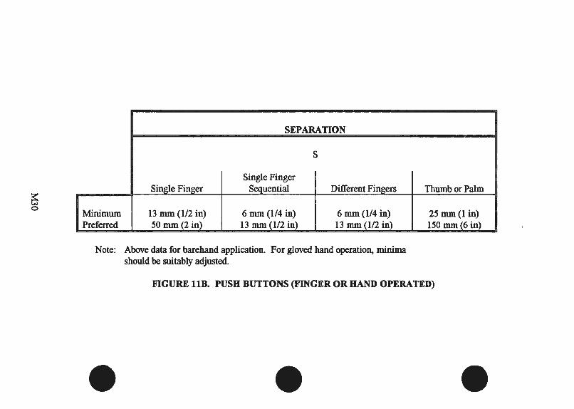
~ 0
SEPARATION
s
Single Finger Single Finger Sequential Different Fingers
Minimum l3 mm (112 in) 6 mm (114 in) 6 mm (114 in) Preferred 50 mm (2 in) 13 mm (112 in) l3 mm (112 in)
Note: Above data for barehand application. For gloved hand operation, minima should be suitably adjusted.
Thumb or Palm
25 mm(l in) 150 mm(6 in)
FIGURE llB. PUSH BUTTONS (FINGER OR HAND OPERATED)
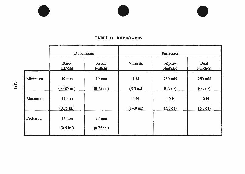
TABLE 10. KEYBOARDS
-
Dimensions Resistance
Bare- Arctic Numeric Alpha- Dual Handed Mittens Numeric Function
Minimum lOmm 19mm lN 250mN 250mN
~ (0.385 in.) {0.75 in.) - (3 .5 oz) (0.9 0~ {0.9 oz)
Maximum 19mm 4N 1.5 N 1.5 N
(0.75 in.) (14.0 oz) (5.3 oz) (5.3 oz)
Preferred 13mm 19mm
(0.5 in.) (0.75 in.)
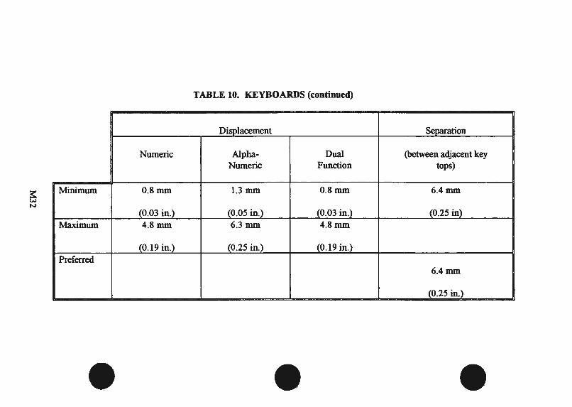
TABLE 10. KEYBOARDS (continued)
Displacement Separation
Numeric Alpha- Dual (between adjacent key Numeric Function tops)
~ Minimum 0.8mm 1.3 mm 0.8mm 6.4mm
N
(0.03 in.) (0.05 in.) (0.03 in.) (0.25 in) Maximum 4.8mm 6.3mm 4.8mm
(0.19 in.) (0.25 in.) (0.19 in.) Preferred
.. . 6.4mm
(0.25 in.)
5.4.3.1.3.6 Feedback
Feedback shall be provided to inform the operator whether:
a. the key was pressed, b. the intended key was pressed, and c. the next operation may be initiated, where applicable.
5.4.3.1.8 Discrete Push-Pull Controls
5.4.3.1.8.1 Applications
Push-pull controls may be used when two discrete functions are to be selected. However, such applications should be used sparingly and for applications in which such configurations are typically expected (e.g., vehicle headlight switch, choke, etc.). They may also be·used in certain cases where limited panel space suggests a miniaturized knob that may be used to serve two related, but distinct functions (e.g., an ON-OFFNolume switch for a T.V. monitor). A three-position push-pull control is acceptable in isolated instances where the criticality of inadvertent selection of the wrong position has no serious consequences (e.g., the typical vehicle headlight switch configuration that provides three "pull" positions-Off/Park/Headlight-plus a rotary panel light and dome light switch).
5.4.3.1.8.2 Handle Dimensions, Displacement and Clearances
Push-pull control handles shall conform to criteria in Table XI.
5.4.3.1.8.3 Rotation
Except for combination push-pull/rotate switch configurations, push-pull control handles shall be keyed to a non-rotating shaft, unless the control is to be used for a special application (e.g., the handle is rotated to disengage the brake setting). When the control system provides a combination push-pull/rotate functional operation, using a round style knob, the rim of the knob shall be serrated to denote (visually and tactually) that the knob can be rotated, and to facilitate a slip-free finger grip.
M33
5.4.3.1.8.4 Detents
Mechanical detents shall be incorporated into push-pull controls to provide tactile indication of positions.
5.4.3.1.8.5 Snagging and Inadvertent Contact
Use, location and operating axis of push-pull type controls shall preclude the possibility of the operator:
a. Bumping a control while getting into or out of position (as in a vehicle).
b. Snagging clothing, communication cables, or other equipment items on the control.
c. Inadvertently deactuating the control setting while reaching for another control.
M34

TABLE XL PUSH-PULL CONTROLS
APPLICATION DESIGN CRITERIA CRITERIA
DIMENSIONS DISPLACEMENT SEPARATION Push-pull control, low resistance, for two- D. MIN C. MIN 25 ±13 mm S,MINSPACE position mechanical DIAM: CLEARANCE: (l ±112") BETWEEN:
~ VI
and/or electrical 19 nun (3/4") 25 mm(l") 38 nun (1-112") systems.
Alternate three position Add 13 nun MIN BETWEEN Add 13 nun plus rotary function (112") PULLPOSNS: (1/2") acceptable for for gloved hand 13 nun (112") for gloved hand application such as vehicle headlight plus parking lights, panel and dome lights provide serrated rim. - -~

5.4.3.1.8.6 Direction of Control Motion
Control direction shall be as follows:
a. Pull towards the operator for ON or actuation; push away for OFF or deactuation.
b. Clockwise for actuation or increasing function of combination pulVrotaty switches.
5.4.3.1.8.7 Resistance
Force for pulling a panel control with fingers should be not more than 18 N (4lb), for pulling aT-bar with four fingers should be not more than 45 N (10 lb).
5.5 Labeling
5.5.2.1 Orientation
Labels and information thereon should be oriented horizontally so that they may be read quickly and easily from left to right. Vertical orientation may be used only when labels are not critical for personnel safety or performance and where space is limited. When used, vertical labels shall read from top to bottom.
5.5.2.2 Location
Labels shall be placed on or very near the items which they identify, so as to eliminate confusion with other items and labels. Labels shall be located so as not to obscure any other information needed by the operator. Controls should not obscure labels.
5.5.2.3 Standardization
Labels shall be located in a consistent manner throughout the equipment and system.
M36
5.5.3.2 Abbreviations
Standard abbreviations shall conform to MIL-STD-12, MIL-STD-411, or MIL-STD-783. If a new abbreviation is required, its meaning shall be obvious to the intended reader. Capital letters shall be used. Periods shall be omitted except when needed to preclude misinterpretation. The same abbreviation shall be used for all tenses and for both singular and plural forms of a word.
5.5.4.1 Brevity
Labels shall be as concise as possible without distorting the intended meaning or information and shall be unambiguous. Redundancy shall be minimized. Where the general function is obvious, only the specific function shall be identified (e.g., frequency as opposed to frequency factor).
5.5.4.2 Familiarity
Words shall be chosen on the basis of operator familiarity whenever possible, provided the words express exactly what is intended. Brevity shall not be stressed if the results will be unfamiliar to operating personnel. For particular users (e.g., maintenance technicians), common technical terms may be used even though they may be unfamiliar to nonusers. Abstract symbols (e.g., squares and Greek letters) shall be used only when they have an accepted meaning to all intended readers. Common, meaningful symbols (e.g.,% and+) maybe used as necessary.
5.5.5.1 Black Characters
Where the ambient illuminance will be above 10 lux (0.9 ft-c), black characters shall be provided on a light background.
5.5.5.4.1 Labels
Labels shall be printed in all capitals; period shall not be used after abbreviations.
M37

5.5.5.5 Letter Width
The width ofletters should be 3/5 of the height, except for "M" and "W", which shall be 4/5 of the height, and "1", which shall be one stroke wide.
5.5.5.6 Numeral Width
The width of numerals shall preferably be 3/5 of the height, except for the "4", which shall be one stroke width wider, and the "1 ", which shall be one stroke wide.
5.5.5.8 Stroke Width Normal
For black characters on a white (or light) background, the stroke width shall be 1/6 to 1/7 of the height.
5.5.5.11 Character Spacing
The minimum space between characters shall be one stroke width.
5.5.5.12 Word Spacing
The minimum space between words shall be the width of one character.
5.5.5.13 Line Spacing
The minimum space between lines shall be one-half character height.
M38
5.5.5.15 Character Height and Viewing Distance
For general dial and panel design, with the luminance nonnally above 3.5 cd/m2 (1 ft-L), character height should conform to the values given below for various distances:
Viewing Distance Minimum Height
a. less than 500 mm (19.7 in) 2.3 mm (0.09 in)
b. 0.5 - 1.0 m (19.7- 39.4 in) 4.7 mm(O.l8 in)
c. 1.0- 2.0 m (39.4 - 78.7 in) 9.4 mm (0.37 in)
d. 2.0- 4.0 m (78.7 - 157.5 in) 19 mm (0.75 in)
e. 4.0-8.0 m (157.4- 315.5 in) 38 mm (1.50 in)
5.5.6.2.4b Location
b. Labels should nonnally be placed above the controls and displays they describe. When the panel is above eye level, labels may be located below if label visibility will be enhanced thereby.
5.5.6.2.4e Location
Label location throughout a system and within panel groupings shall be uniform.
M39/M40


APPENDIXM2
ESD-TR-86-278
Guidelines For Designing User Interface Software
M41
1. Data Entry
1.0 General
1.0.9 Explicit ENTER Action
Always require a user to take an explicit ENTER action to initiate processing of entered data; do not initiate processing as a side effect of some other action.
EXAMPLE: As a negative example, returning to a menu of control options should not by itself result in computer processing of data just keyed onto a display.
EXCEPTION: In routine, repetitive data entry transactions, successful completion of one entry may automatically lead to initiation of the next, as in keying ZIP codes at an automated post office.
COMMENT: Deferring processing until after an explicit ENTER action will permit a user to review data and correct errors before computer processing. This is particularly helpful when data entry is complex and/or difficult to reverse.
1.0.11 Explicit CANCEL Action
Require a user to take an explicit action in order to cancel a data entry; data cancellation should not be accomplished as a side effect of some other action.
EXAMPLE: As a negative example, casual interruptions of a data entry sequence, such as paging through forms or detouring to HELP displays, should not have the effect of erasing partially completed data entries.
COMMENT: If a requested sequence control action implies a more definite interruption, such as LOG-OFF command or a command to return to a menu display, then the user should be asked to confirm that action and alerted to the loss of any data entries that would result.
· M42
1.0.12 Feedback for Completion of Data Entry
Ensure that the computer will acknowledge completion of a data entry transaction with a confirmation message if data entry was successful, or else with an error message.
EXCEPTION: In a sequence of routine, repetitive data entry transactions, successful completion of one entry might result simply in regeneration of the initial (empty) data entry display, in order to speed the next entry in the sequence.
COMMENT: Successful data entry should not be signaled merely by automatic erasure of entered data from the display, except possibly in the case of repetitive data entries. For single data entry transactions, it may be better to leave entered data on the display until the user takes an explicit action to clear the display.
1.0.13 Feedback for Repetitive Data Entries
For a repetitive data entry task that is accomplished as a continuing series of transactions, indicate successful entry by regenerating the data entry display, automatically removing the just-entered data in preparation for the next entry.
COMMENT: Automatic erasure of entered data represents an exception to the general principle of control by explicit user action. The interface designer may adopt this approach, in the interest of efficiency, for data entry transactions that task analysis indicates will be performed repetitively.
COMMENT: In addition to erasure of entered data, a message confirming successful data entry might be displayed. Such a message may reassure uncertain users, especially in system applications where computer performance is unreliable.
M43
1.0.14 Feedback when Changing Data
If a user requests change (or deletion) of a data item that is not currently being displayed, offer the user the option of displaying the old value before confirming the change.
EXCEPTION: Expert users may sometimes wish to implement data changes without displayed feedback. as in global replace transactions, accepting the attendant risk.
COMMENT: Displayed feedback will help prevent inadvertent data change, and is particularly useful in protecting delete actions. Like other recommendations intended to reduce error, it assumes that accuracy of data entry is worth extra effort by the user. For some tasks, that may not be true.
1.0.24 Prompting Data Entry
Provide prompting for the required formats and acceptable values for data entries.
EXAMPLE: {Good) Vehicle type: _ c=Car t=Truck b=Bus
(Bad) Vehicle type: _
EXCEPTION: Prompting may not be needed by skilled users and indeed may hinder rather than help their performance in situations where display output is slow (as with Teletype displays); for such users prompting might be provided as an optional aid.
COMMENT: Prompting is particularly needed for coded data entries. Menu selection may be appropriate for that purpose, because menu selection does not require the user to remember codes but merely to choose among displayed alternatives. Other methods of prompting include labeling data fields, such as: Vehicle type (cit/b):_ and/or providing optional guidance displays.
M44

1.3 Text
1.3.32 Confirming Actions in DELETE Mode
If a DELE1E mode is used, highlight any text specified by a user for deletion and require the user to confirm the DELE1E action before the computer will process it.
COMMENT: Requiring a user to confirm actions in DELE1E mode is particularly important when the control entries for cursor positioning (e.g., WORD, SENTENCE, PARAGRAPH, PAGE) are also used to specify text for deletion, which is often the case. Users will associate the specification of text units primarily with cursor positioning, which is the most frequent action in text editing. In a DELE1E mode, after specifying text units for deletion, a user may press a PARAGRAPH key intending to move to the next paragraph but accidentally delete the next paragraph. Confirmation of DELE1E actions will tend to prevent such errors.
COMMENT: An alternative approach to this problem is not to provide a continuing DELE1E mode, but instead require double keying to accomplish deletions. In a DELE1E mode, a user might press a DELE1E key followed by unlimited repetitions of a WORD key (or keys specifying other units of text). With double keying, the user would have to press DELE1E before each selection of a text unit to be deleted.
M45
1.3.33 Reversible Actions
Design text editing logic so that any user action is immediately reversible.
EXAMPLE: If a user centers a heading and then decides it would look better flush against the left margin, an UNDO action should reverse the centering and move the heading back to its original location.
EXAMPLE: If a user underlines a paragraph of text and then decides it should be in all capital letters instead, an UNDO action should reverse the underlining. The user should not be required to delete the paragraph and retype it just to erase the underscoring.
COMMENT: Reversible actions are particularly important in a text editing environment because text formatting often involves experimentation with features such as underscoring, holding, and spacing. If users know that they can reverse whatever they do, they will feel more free to delete text and experiment with formatting features.
COMMENT: An UNDO capability is currently available in some interface designs. In some applications, however, this capability is provided through the use of an UNDO key which can only reverse the most recent control action. For text editing, users must be able to reverse such formatting features as centering and holding at any time. Therefore, if control actions are to be made reversible, an UNDO action should be able to reverse more than the most recent command, perhaps by requiring the user to specify which command to undo, and/or to place the cursor at the location of the format feature that is to be reversed.
COMMENT: When text segments have been deleted, it should be possible to retrieve more than the most recent deletion. Some systems do this by storing all deletions in a special file. Deleted text which the user wishes to retrieve can then be moved from the deletion file to the file in which the user is presently working.
M46

1.3.34 User Confirmation of Editing Changes
When a user signals completion of document editing, allow the user to confirm that changes should be made to the original document, or else to choose alternative options.
3.
COMMENT: A user will generally wish to replace the original document with its edited version. However, sometimes a user may decide that editing mistakes have been made, and wish to discard the new version while saving the original. Or a user might wish to save the new version as a separate document, while saving the original unchanged. Such decisions can be made best at the end of an editing session, when the user knows what has been accomplished, rather than before a session is begun.
COMMENT: During text editing, the computer should always retain a copy of the original document until the user confirms that it should be changed. The original document should not be changed automatically as the user enters each editing change.
Sequence Control
3.0.1 Flexible Sequence Control
Provide flexible means of sequence control so that users can accomplish necessary transactions involving data entry, display, and transmission, or can obtain guidance as needed in connection with any transaction.
EXAMPLE: In scanning a multipage display the user should be able to go forward or back at will. If user interface design permits only forward steps, so that the user must cycle through an entire display series to reach a previous page, that design is deficient.
COMMENT: Necessary transactions should be defined in task analysis prior to software design.
M47
3.0.7 Logical Transaction Sequences
When designing a sequence of related transactions for some information handling task, employ task analysis to ensure that those transactions will constitute a logical unit or subtask from a user's viewpoint, and to determine what control options users will need at any point.
3.5
COMMENT: A logical unit to the user is not necessarily the same as a logical unit of the computer software that mediates the transaction sequence. It might be, for example, that a user should enter ten items of data in a single transaction, because those data all come from one particular paper form, even though the computer will use five of those items for one purpose and five items for another in its subsequent internal processing.
Error Management
3.5.7 User Confirmation of Destructive Entries
When a control entry will cause any extensive change in stored data, procedures and/or system operation, and particularly if that change cannot be easily reversed, notify the user and require confirmation of the action before implementing it.
3.5.9 Distinctive CONFIRM Action
Provide an explicitly labeled CONFIRM function key, different from the ENTER key, for user confirmation of questionable control and data entries.
COMMENT: Confirmation should not be accomplished by pushing some other key twice.
COMMENT: Some interface designers recommended that in special cases confirmation should be made more difficult still, (e.g., by keying the separate letters C-0-N-F-1-R-M). Even such extreme measures, however, cannot guarantee that users will not make errors.
M48
3.5.10 UNDO to Reverse Control Actions
Ensure that any user action can be immediately reversed by an UNDO command.
EXAMPLE: If a user is overhasty in confinning a destructive action, and realizes the mistake right away (i.e., before taking another action), then an UNDO action might be taken to reverse the damage.
COMMENT: UNDO itself should be reversible, so that a second UNDO action will do again whatever was just undone.
COMMENT: Such an UNDO capability is currently available in many interface designs, and should be provided more generally. Even with an UNDO capability, however, a user may make an irretrievable mistake, if succeeding actions intervene before a prior destructive action is noticed.
3.5.13 Flexible BACKUP for Error Correction
Allow users to BACKUP easily to previous steps in a transaction sequence in order to correct an error or make any other desired change.
4. User Guidance
4.0 General
4.0.16 Familiar Wording
When wording labels, prompts and user guidance messages, adopt terminology familiar to users.
EXAMPLE:
(Good)
(Bad)
Data requires special access code; call Data Base Admin, X 9999.
IMSNS DBMS private data; see DBSA, 0/99-99.
M49
4.0.17 Task-Oriented Wording
Adopt task-oriented wording for labels, prompts and user guidance messages, incorporating whatever special terms and technical jargon may be customarily employed in the users' tasks.
COMMENT: Jargon terms maybe helpful, ifthey represent the jargon of the user and not of the designer or programmer. The rule here should be to know the users and adapt interface
design to their vocabulary instead offorcing them to learn new wording.
4.0.18 Wording Consistent with Control Entry
Choose wording for user guidance that is consistent with the words used for control entries.
EXAMPLE:
(Good) To delete a paragraph, press DELETE and then PARAGRAPH.
(Bad) To erase a paragraph, press DELETE and then PARAGRAPH.
EXAMPLE: If a user must complete a control form to specify printer settings, the words used as labels on that form should also be used in any error messages and HELP displays which may guide that process.
COMMENT: When selecting or composing control entries, a user will tend to mimic the vocabulary, format, and word order used in computer displays, including labels, error messages, HELP displays, etc. If displayed wording is consistent with required entries, a user will be more likely to make a correct entry on the first try.
M50
4.0.18 Wording Consistent with Control Entry (Continued)
4.3
4.3.1
COMMENT: Consistent wording of user guidance will be particularly helpful for dialogues based on constrained natural _ language. If a designer begins by detennining which words and fonnats users are likely to choose naturally, and then reinforces that usage by incorporating such wording in user guidance, much of a user's interaction with the computer will be predictable. Therefore, the "natural language" need not accommodate the full range of possible entries, but only those entries which users are likely to make.
Error Feedback
Informative Error Messages
When the computer detects an entry error, display an error message to the user stating what is wrong and what can be done about it.
EXAMPLE:
(Good) Code fonnat not recognized; enter two letters, then three digits.
(Bad) Invalid input.
COMMENT: Users should not have to search through reference infonnation to translate error messages.
COMMENT: Error messages can be regarded as the most important form of system documentation. Well designed error messages will give help to users automatically, at the point where help is most needed.
M5-l
4.3.3 Task-Oriented Error Messages
Adopt wording for error messages which is appropriate to a user's task.
EXAMPLE:
(Good) Contract number not recognized; check the file and enter a current number.
4.3.~
(Bad) Entry blocked. Status Flag 4.
COMMENT: Error messages that can be understood only by experienced programmers (and interface designers) will have no value for ordinary users.
Brief Error Messages
Make error messages brief but informative.
EXAMPLE:
(Good) Entry must be a number.
(Bad) Alphabetic entries are not acceptable because this entry will be processed automatically.
COMMENT: Often a user will recognize that an error has been made, and the message will serve merely as a confirming reminder. In such instances, short error messages will be scanned and recognized more quickly.
COMMENT: For a user who is truly puzzled, and who needs more information than a short error message can provide, auxiliaty HELP can be provided either on-line or by reference to system documentation.
M52
4.3.5 Brief Error Messages (Continued)
COMMENT: If an on-line HELP explanation is not available, a user may have to refer to system documentation for a coded listing of possible errors. Under those circumstances, some designers display each error message with an identifying code, to facilitate rapid reference to documentation. That practice might help experienced users, who would gradually come to recognize the codes.
4.3.6 Neutral Wording for Error Messages
Adopt neutral wording for error messages; do not imply blame to the user, or personalize the computer, or attempt to make a message humorous.
EXAMPLE:
(Good) Entry must be a number.
(Bad) lllegal entry . .
(Bad) Don't be dumber, use a number
COMMENT: Error messages should reflect a consistent view that the computer is a tool, with certain limitations that a user must take into account in order to make the tool work properly. If error messages reflect an attitude that the computer (or its programmer) imposes rules, or establishes "legality", the user may feel resentful. If error messages reflect personalization of the computer, as if it were a friendly colleague, a naive user may be misled to expect human abilities the machine does not actually possess. If error messages are worded humorously, any joke will surely wear thin with repetition, and come to seem an intrusion on a user's concern with efficient task performance.
COMMENT: The same considerations apply for the wording of computer-generated prompts and other instructional material.
M53
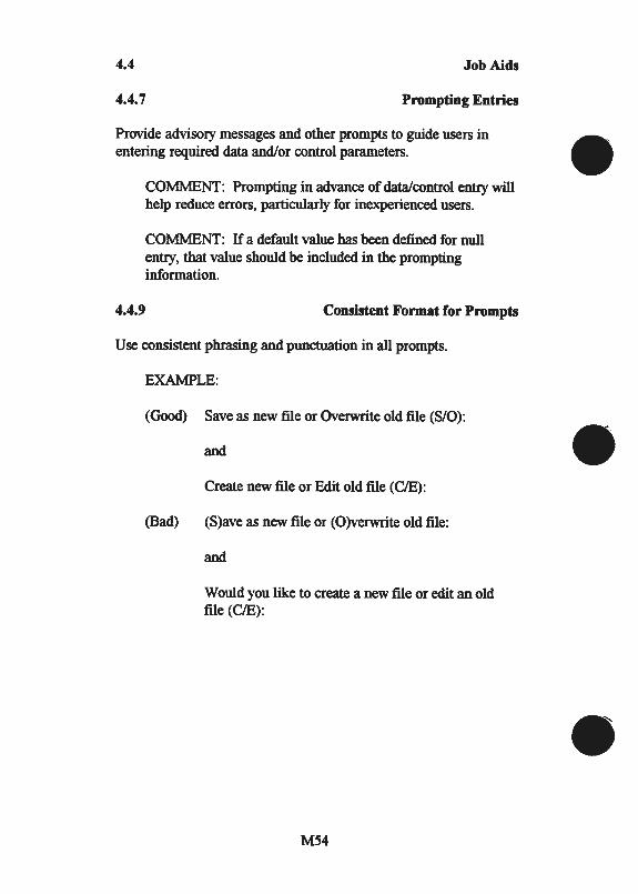
4.4 Job Aids
4.4.7 Prompting Entries
Provide advisory messages and other prompts to guide users in entering required data and/or control parameters.
COMMENT: Prompting in advance of data/control entry will help reduce errors, particularly for inexperienced users.
COMMENT: If a default value has been defined for null entry, that value should be included in the prompting information.
4.4.9 Consistent Format for Prompts
Use consistent phrasing and punctuation in all prompts.
EXAMPLE:
(Good) Save as new file or Overwrite old file (S/0):
and
Create new file or Edit old file (C/E):
(Bad) (S)ave as new file or (O)verwrite old file:
and
Would you like to create a new file or edit an old file (C/E):
M54

a: w :X:
b d

IO
sp.nrpUBJS UO!-J8.1~JUJ swa)SAS UV:W
(V • Aall) 000£ HJ...tl VSVN
10 XI<IN:FlddV
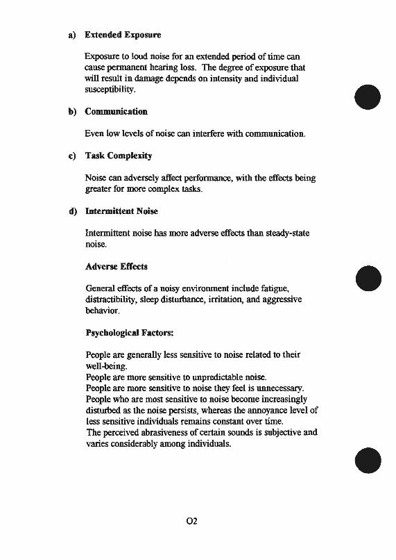
a) Extended Exposure
Exposure to loud noise for an extended period of time can cause permanent hearing loss. The degree of exposure that will result in damage depends on intensity and individual susceptibility.
b) Communication
Even low levels of noise can interfere with communication.
c) Task Complexity
Noise can adversely affect performance, with the effects being greater for more complex tasks.
d) Intermittent Noise
Intermittent noise has more adverse effects than steady-state noise.
Adverse Effects
General effects of a noisy environment include fatigue, distractibility, sleep disturbance, irritation, and aggressive behavior.
Psychological Factors:
People are generally less sensitive to noise related to their well-being. People are more sensitive to unpredictable noise. People are more sensitive to noise they feel is unnecessary. People who are most sensitive to noise become increasingly disturbed as the noise persists, whereas the annoyance level of less sensitive individuals remains constant over time. The perceived abrasiveness of certain sounds is subjective and varies considerably among individuals.
02
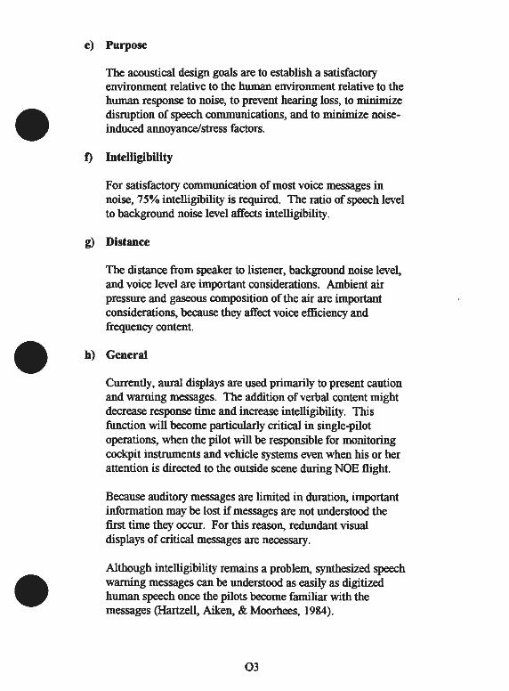
e) Purpose
The acoustical design goals are to establish a satisfactory environment relative to the human environment relative to the human response to noise, to prevent hearing loss, to minimize disruption of speech communications, and to minimize noiseinduced annoyance/stress factors.
f) Intelligibility
For satisfactory communication of most voice messages in noise, 75% intelligibility is required. The ratio of speech level to background noise level affects intelligibility.
g) Distance
The distance from speaker to listener, background noise level, and voice level are important considerations. Ambient air pressure and gaseous composition of the air are important considerations, because they affect voice efficiency and frequency content.
h) General
Currently, aural displays are used primarily to present caution and warning messages. The addition of verbal content might decrease response time and increase intelligibility. This function will become particularly critical in single-pilot operations, when the pilot will be responsible for monitoring cockpit instruments and vehicle systems even when his or her attention is directed to the outside scene during NOE flight.
Because auditory messages are limited in duration, important information may be lost if messages are not understood the first time they occur. For this reason, redundant visual displays of critical messages are necessary.
Although intelligibility remains a problem, synthesized speech warning messages can be understood as easily as digitized human speech once the pilots become familiar with the messages (Hartzell, Aiken, & Moorhees, 1984).
03
h) General (Continued)
Synthetic voice messages are attention getting because the voice quality is different than human communications. Synthetic speech places greater demands on short-term memory and does not have the same redundancy as human speech. Furthermore, there is a greater decrement in intelligibility for synthesized messages presented in a noisy background (Crittenden, 1986).
04


APPENDIX02
SAE/AIR 1093
Numeral, Letter and Symbol Dimensions For Aircraft Instrument Displays
05
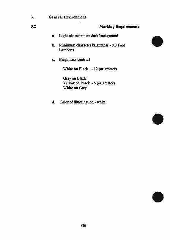
3. General Environment
3.2 Marking Requirements
a. Light characters on dark background
b. Minimum character brightness - 0.3 Foot Lamberts
c. Brightness contrast
White on Black - 12 (or greater)
Gray on Black Yellow on Black - 5 (or greater) White on Grey
d. Color of illumination - white
06
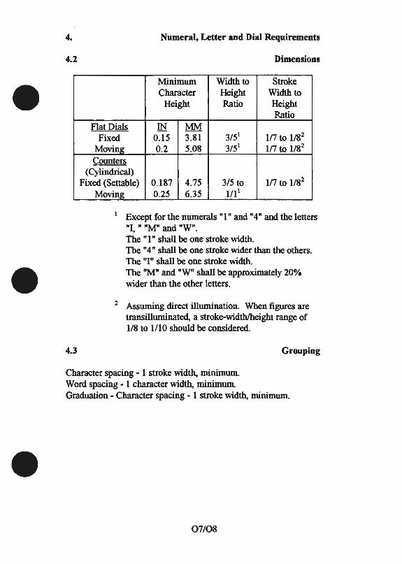
4.
4.2
4.3
Numeral, Letter and Dial Requirements
Dimensions
Minimum Width to Stroke Character Height Width to
Height Ratio Height Ratio
Flat Dials IN MM Fixed 0.15 3.81 3/51 1/7 to 1/82
Moving 0.2 5.08 3/51 1/7 to 1/82
Counters (Cylindrical)
Fixed (Settable) 0.187 4.75 3/5 to 117 to 1/82
Moving 0.25 6.35 1111
1 Except for the numerals "1" and "4" and the letters "I, " "M" and "W". The "1" shall be one stroke width. The "4" shall be one stroke wider than the others. The "I" shall be one stroke width. The "M" and "W" shall be approximately 20% wider than the other letters.
2 Assuming direct illumination. When figures are transilluminated, a stroke-width/height range of 1/8 to 1/10 should be considered.
Grouping
Character spacing - 1 stroke width, minimum. Word spacing - 1 character width, minimum. Graduation - Character spacing - 1 stroke width, minimum.
07/08


APPENDIX OJ
SAE/ARP 571C
Flight Deck Controls And Displays For Communication And Navigation Equipment
For Transport Aircraft
09
7. Displays
7.2 Display Devices
7.2.2 Character Size
Character styles and height-to-width ratio shall be 0.65 minimum with a height of no less than 20 arc minutes (0.006 Radians) of visual angle for the overhead panel and no less than 15 arc minutes (0.0045 Radians) of visual angle for all other applications.
7.2.3 Legibility
The display shall be legible under all normally encountered ambient lighting conditions. Means of display brightness adjustment shall be provided. Automatic adjustment after the crew's initial setting is desirable. The display shall be designed so that the flight crew will not be exposed to undue fatigue due to flickering, unfocused characters, etc.
7.3 Dedicated Displays
7.3.3 Navigation Equipment Displays
It is desirable that the Captain and First Officer each be provided with indication of all navigational information; however, it is permissible, as specified in this ARP, to provide a single display common to both pilots.
Where a display may be switched to provide information to the crew from more than one source, means must be provided to indicate clearly to which source the display is currently connected. Display of selected source must be in the direct vision of the respective crew member when looking at the relevant display, and shall give an indication consistent with navigation control selection.
If auto-tune is considered, station identification shall be displayed, and frequency may be displayed.
010


APPENDIX04
SAE/ARP 1874
Design Objectives For CRT Displays For Part 25 (Transport) Aircraft
011

5.1 Display Physical Characteristics
5.1.3 Symbol Alignment
Symbols which are interpreted relative to each other (that is, cursors on scales, command bars against reference points, etc.) shall be aligned at their midpoints to within 0. 7 mr from any point within the instrument's viewing envelope.
5.1.10 Symbol Quality
Symbols should have a high quality painted-on appearance with no bright spots, tails, squiggles, skews, or gaps; the distorted dimension should not exceed one half the local line width.
5.1.12 Symbol Motion
For those elements of the display that are normally in motion, any jitter, jerkiness or ratcheting effect shall not be distracting or objectionable.
5.2 Photo-Colormetric Characteristics
5.2.1 General
The display symbology should be clearly readable under all ambient lighting levels ranging from 1.1 1x (0.1 fc) to sunshafting illumination of 86 400 1x (8000 fc) at 45 deg incidence to the face of the display.
5.2.2 Luminance
The display luminance shall be sufficient to provide a comfortable level of viewing with rapid adaptation when transitioning from looking outside the cockpit. These recommendations were developed from tests in which symbology not only had to be readable in the extreme ambient conditions, but the color of the symbology had to be ascertained without regard to symbol shape.
012

5.2.2.1 Maximum Luminance
With manual and automatic luminance controls at a maximum, the display luminance of the primary colors when measured in a dark ambient should be at least the following for application in which symbols are single line construction (larger geometries need less luminance) and area subjects that present meaningful information (for example, weather radar) rather than just an aesthetic background. This luminance requirement (in units of candela per square meter and foot lamberts) shall apply over the normal useful life of the equipment including end-of-life.
Symbol Lines Area Subjects
Red 48 cd/m2 (14 fL) 9.3 cd/m2 (2.7 fL) Green 103 cd/m2 (30 fL) 20 cd/m2 (5.8 fL)
Blue 17 cd/m2 ( 5 fL) 3.9 cd/m2 (1.15 fL)
Based on subject with 0.67 mr line width
5.2.2.2 Minimum Luminance
To achieve acceptable viewing in dark conditions, the minimum display luminance of the primary colors under which the performance requirements of this ARP shall be met when measured in a dark ambient should be no greater than:
Symbol Lines Area Subjects
Red 0.192 cd/m2 (0.056 fL) 0.113 cd/m2 (0.033 fL) Green 0.420 cd/m2 (0.120 fL) 0.247 cd/m2 (0.072 fL)
Blue 0.068 cd/m2 (0.024 fL) 0.041 cd/m2 (0.012 fL)
Where applicable, the automatic brightness control shall be inhibited for these requirements.
NOTE: These minimum luminance values have been established for dark-adapted cockpits. These values may be increased for applications where the cockpit ambient lighting design precludes a high degree of night vision adaptation.
013
5.2.2.2 Minimum Luminance (Continued)
Under night lighting, with the display brightness set at the lowest usable level for flight with normal symbology, all flags and annunciators shall be adequately visible.
5.2.3 Color
Color definitions shall be based on the CIE 1976 Uniform Chromaticity Scale u', v' coordinates.
5.2.4 Color Uniformity
A symbol of a specified color shall have a chrominance which is uniform over the entire screen. The chromaticity difference (CD) between any two points on the screen of the same color shall not exceed 0.034.
5.2.5 Color Difference
Displayed symbology shall be distinguished from its background and from other symbols by means of luminance differences or chromaticity differences, or both, in all ambient conditions defined in 5.2.1.
The most credible color different system is CIELUV, which is described in Supplement 2 to CIE Publication No. 15; but it does not consider symbol size and does not offer criteria for perception. Except in cases where an absolute chromaticity is desired (for example, robin's egg blue for sky shading), colors should be selected which maximize color differences. Results should be analyzed using the CRITERIA system. There is no adequate basis for specifying a minimum acceptable difference at this time.
5.2.6 Reflections
The display surface should have a reflection-reducing coating with performance characteristics per AMS 2521A. Surfaces in the optical path should be treated appropriately to reduce specular reflections.
014


~10
lOlt dliV/'JIVS
SO XION'JlddV
7: Color
7.1 General
7.1.1
Color shall have the same operational significance throughout the flight deck for all mechanical, electromechanical, and electronic equipment.
7.1.2
Color coding shall be supported by a redundant means of coding (e.g., shape, position, function) for all operationally significant indications.
7.1.3
Color shall be used with the aim of enhancing the distinction between indications, symbols and annunciations, but the number of colors and extent of usage should be minimized to avoid loss of discrimination.
7.1.4
Colors shall maintain their discriminability over the full range of ambient light conditions (dark night to direct sunlight) and all brightness settings.
7.2 Color Set
7.2.1
Colors shall be selected from the following set of nine: Red, Tan/Brown, Amber, Yellow, Green, Cyan, Blue, Magenta, and White.
NOTE: Care must be taken to ensure that sufficient contrast is maintained where red, brown, or amber colors are superimposed or used in close proximity to each other.
016
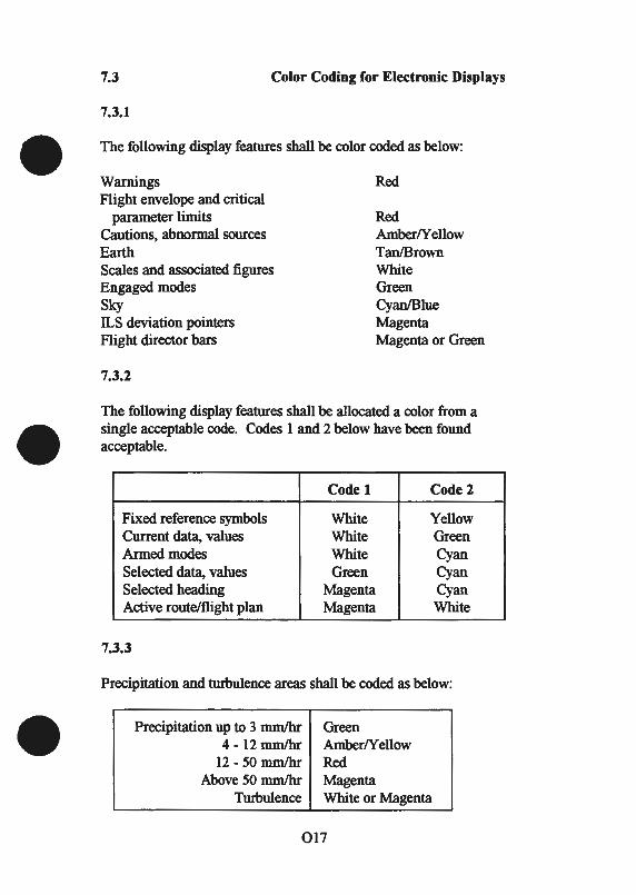
7.3 Color Coding for Electronic Displays
7.3.1
The following display features shall be color coded as below:
Warnings Flight envelope and critical
parameter limits Cautions, abnonnal sources Earth Scales and associated figures Engaged modes Sky ILS deviation pointers Flight director bars
7.3.2
Red
Red Amber/Yellow Tan/Brown White Green Cyan/Blue Magenta Magenta or Green
The following display features shall be allocated a color from a single acceptable code. Codes 1 and 2 below have been found acceptable.
Codel Codel
Fixed reference symbols White Yellow Current data, values White Green Armed modes White Cyan Selected data, values Green Cyan Selected heading Magenta Cyan Active route/flight plan Magenta White
7.3.3
Precipitation and turbulence areas shall be coded as below:
Precipitation up to 3 mm/hr 4-12 mm/hr
12-50 mm/hr Above 50 mm/hr
Turbulence
Green Amber/Yellow Red Magenta White or Magenta
017
7.3.4
Bearing pointers should be color coded to comply with paragraph 7.1.1.
7.3.5
Background color (grey or other shade) may be used to enhance display presentation and improve legibility.
018


610
LllOl t dliV/3VS
90 XIGN:iddV
6.3 Primary Flight Instruments-EHSI/ND
6.3.1
The instrument shall provide a clear and unmistakable display of aircraft position, heading the track relative to desired course/track. It shall require a minimum of pilot computation or interpretation.
6.3.2
In addition to the compass rose format EHSI/ND equipment shall generate a moving map format upon which weather radar data may be superimposed, and should provide a plan format for verification of stored flight plans.
6.3.3
The compass rose format when installed shall present the following information:
(i) Magnetic/true heading/track and scale (ii) Selected heading
(iii) Selected source/desired track (iv) Aircraft reference symbol (v) Vertical path deviation and scale
(vi) Lateral path deviation and scale (vii) Bearing pointer(s) (optional) (viii) To/from indication (ix) Distance to waypoint (x) Annunciation of manually selected navaids
(xi) Failure flags
020
6.3.4
The map format shall incorporate the following features:
(i) Data areas shall not degrade moving symbols or tracks (ii) Alphanumeric legends shall remain upright with map
rotation except compass numerals on the heading scale (iii) Waypoints, VORs, NDBs, airports, reporting points,
intersections, etc., shall be identified by conventional terminology and abbreviations
(iv) Symbols shall reflect accepted navigation chart usage (v) Courses and desired track lines shall remain in view when
their origin or termination is not visible (vi) Actual courses or projected track lines shall be clearly
distinguishable when coincident with planned courses or track angles
(vii) Movement of symbols and lines shall be smooth during map rotation and parameter selection
(viii) Automatic and/or manual de-clutter as a function of flight phase shall be provided
6.3.5
The map format shall present the following information:
Items (i), (ii), (iii), (iv), (ix), (x), (xi), of paragraph 6.3.3 and:
(xii) Lateral path deviation from desired track (xiii) Wind speed and direction (if available) (xiv) Range marks/scale (xv) Weather radar data identifying precipitation rates and/or
turbulence levels (xvi) Active flight plan (xvii) Waypoint/VOR/NDB/ Airport/Reporting point/Intersection
data
021
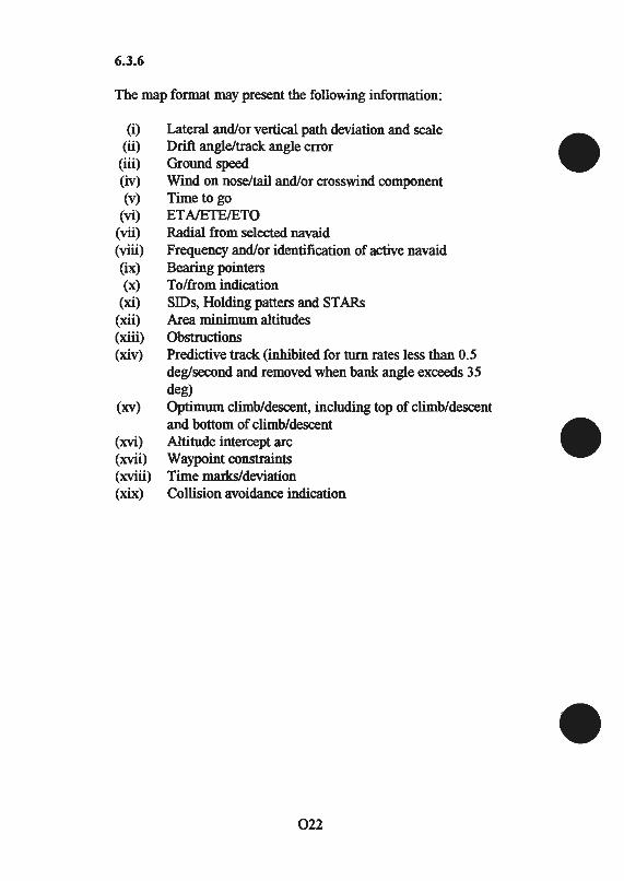
6.3.6
The map format may present the following information:
(i) Lateral and/or vertical path deviation and scale (ii) Drift angle/track angle error
(iii) Ground speed (iv) Wind on nose/tail and/or crosswind component (v) Time to go
(vi) ET NETEIETO (vii) Radial from selected navaid (viii) Frequency and/or identification of active navaid (ix) Bearing pointers (x) To/from indication
(xi) SIDs, Holding patters and STARs (xii) Area minimum altitudes (xiii) Obstructions (xiv) Predictive track (inhibited for turn rates less than 0.5
deg!second and removed when bank angle exceeds 35 de g)
(xv) Optimum climb/descent, including top of climb/descent and bottom of climb/descent
(xvi) Altitude intercept arc (xvii) Waypoint constraints (xviii) Time marks/deviation (xix) Collision avoidance indication
022


APPENDIX07
SAE/AS 8034
Minimum Performance Standard For Airborne Multipurpose Electronic Displays
023

3.1
3.1.1.6 Integral Lighting
4.2 Viewing Characteristics
4.2.2 Symbol Alignment
Symbols which are interpreted relative to each other, including mechanically produced symbols that are interpreted relative to electronically produced symbols, shall be aligned, including parallax misinterpretation of information.
4.2.3 Positional Accuracy
The display absolute positional accuracy shall be better than 5% of the maximum diagonal dimension of the display. In no case shall the absolute positional error cause erroneous data to be presented.
4.2.5 Line Width
Line widths shall be of sufficient size and sharpness to display the intended information with no distracting visual effects or ambiguities.
4.2.8 Symbol Quality
Lines, symbols, and characters shall have no tails, squiggles, skews, or gaps discernible from the design eye viewing envelope which cause erroneous interpretation.
4.3 Photocolorimetric Characteristics
4.3.2.1 Luminance
The display luminance shall be sufficient to provide a usable display under the maximum ambient illumination level appropriate to the display type (as defined in paragraph 2 of this AS) and application.
024
4.3.2.2 Luminance Uniformity
The luminance of a given symbol, line, character, or generated background shall not vary more than:
1) ±30% when located within the useful display area, or 2) ±2Q4'1o when located within the central80% of the
useful display area.
These requirements apply for any luminance control setting.
4.3.2.3 Manual Luminance Control
The display system shall have capability for manual luminance control.
4.3.2.4 Automatic Luminance Control
If the display system has automatic luminance compensation, the operation of this compensation shall function so that the system meets the requirements of paragraph 4.3.1 under changing cockpit ambient light levels. Manual luminance control shall not be adversely affected by failure of the automatic luminance control.
4.3.2.5 Luminance Tracking
When the luminance of the display is varied from maximum to minimum, the relative luminance of all displayed symbols, characters, lines, and generated backgrounds shall visually remain constant. In no case shall any symbols or characters become invisible at the minimum luminance setting while other characters or symbols are visible.
4.3.3 Color
Where multiple colors are used to enhance discrimination, the use of color shall not result in the erroneous ambiguous interpretation of the displayed information. In no case should colors be selected which conflict with the requirements of paragraph 4.3.1.
In general, color should not be used as the only coding dimension for critical information.
025

4.3.4 Color Uniformity
The color difference between any symbols of the same color located at any position within the useful display area shall not be sufficient to cause an ambiguity or an incorrect identification of an assigned color over the entire range of luminance control.
4.3.5 Convergence
When a display element is a composite of multiple traces (such as multiple guns of a shadow mask CRT, or alternate fields of a beam penetration CRn, the beam centers shall be converged. This convergence value at any point shall be within the average of the line widths of the respective traces at that point. This requirement applies over the useful display area for all symbol intensity settings.
026


ao
SJdOl~U03 s.IOJJ8.!{
UBWDH :..cloJouq~a.L ABJdS!G
80XIGN~ddV
a) While the use of auditory information may help to alleviate visual clutter, overuse can lead to auditory clutter (p. 48). Auditory displays are, by their very nature, intrusive and distracting. They may, under certain conditions, disrupt concentration. Simon and Marchionda-Frost (1984) point out that the listener typically does not comprehend the meaning of a speech message until transmission is nearly complete.
b) p. 4 9 - The use of speech is likely to be more effective in conditions of high workload and stress, when the meaning of coded signals may well be forgotten {Edman, 1982).
c) Nonspeech signals may be more easily comprehended by users who have hearing difficulties as well as by those who are not familiar with spoken English.
028


BffiLIOGRAPHY
Advisory Circular 25-11. Transport category airplane electronic display systems. Washington, DC: U.S. Department of Transportation's Federal Aviation Administration, July 1987.
Aerospace Information Report 1093. Numeral, letter and symbol dimensions for aircraft instrument displays. Warrendale, P A: Society of Automotive Engineers, December 1969.
Aerospace Recommended Practice 57 I C. Flight deck controls and displays for communication and navigation equipment for transport aircraft. Warrendale, PA: Society of Automotive Engineers, October 1985.
Aerospace Recommended Practice 1874. Design objectives for CRT displays for part 25 (transport) aircraft. Warrendale, PA: Society of Automotive Engineers, May 1988.
Aerospace Recommended Practice 4102. Flight deck panels, controls, and displays. Warrendale, PA: Society of Automotive Engineers, July 1988.
Aerospace Recommended Practice 4102/7. Electronic displays. Warrendale, PA: Society of Automotive Engineers, July 1988.
Aerospace Standard 8034. Minimum performance standard for airborne multipurpose electronic displays. Warrendale, PA: Society of Automotive Engineers, December 1982.
Federal Aviation Administration (FAA). Airborne supplemental navigation equipment using the global positioning system (GPS). (TSO-Cl29 AI). Washington, DC, December 1992.
Federal Aviation Administration (FAA). Airworthiness approval of global positioning system (GPS) navigation equipment for use as a VFR and IFR supplemental navigation system. (FAA-AC-20-138). Washington, DC, May 1994.
Bl

FAA Type Inspection Authorization. Installation of the GARMIN GPS 155 (First-time IFR en route, terminal, and non-precision approach approval) in the Mooney M2aJ. (Project No. ST0346WI-A). Washington, DC: U.S. DOT FAA, January 1994.
Military Standard 1472D. Human engineering design criteria for military systems, equipment and facilities. Washington, DC: U.S. Department of Defense, March 1989.
National Aeronautics and Space Administration. Man systems integration standards, vol. 1 (rev. A .). (NASA FTB 3000). August 1989.
Radio Technical Commission for Aeronautics. Minimum operational performance standards for airborne supplemental navigation equipment using global positioning system. (RTCA/D0-208). Washington, DC: RTCA, July 1991.
Smith, S. L. & Mosier, J. N. Guidelines for designing user interface software. (ESD-TR-86-278). Bedford, MA: Mitre, August 1986.
Stokes, A., Wickens, C. & Kite, K. Display technology: Human factors concepts. Warrendale, PA: Society of Automotive Engineers, 1990.
B2 @