FA1 Instruction Manual10 / 42 Instruction manual FA1... If our standard types do not correspond with...
42
Instruction manual FA1... NAN-KD-0006-en_V02.03 | 10/12/2014
Transcript of FA1 Instruction Manual10 / 42 Instruction manual FA1... If our standard types do not correspond with...

Instruction manual FA1...
NAN-KD-0006-en_V02.03 | 10/12/2014
| Issue NORIS Automation GmbH
2 / 42 Instruction manual FA1...
IssueInformation on issueDocument ID NAN-KD-0006-de/enIssue V02.03Date December 2014
Issued by© 2014 - NORIS Automation GmbH Muggenhofer Str. 95 90429 Nürnberg Tel: +49 911 3201 0 Fax: +49 911 3201 150 Email: [email protected]

NORIS Automation GmbH Table of contents
Instruction manual FA1... iii
Table of contents1 General information 5
2 General information on this instruction manual 72.1 Scope of validity 7
2.2 Subject of the operating instructions 7
2.3 Design and use of safety and warning notes 7
2.4 Scope of delivery 8
2.5 Accessories and spare parts 8
2.6 Type code 9Type code FAJ11 9Type code FAJ12 10Type code FAH11 11Type code FAH12 12
3 Product description 133.1 Scope of application 13
3.2 Measuring principle 13
3.3 Peculiarities and differences 13
3.4 Speed sensor design 143.4.1 General structure 143.4.2 Connection variants 153.4.3 Signal types and output level 153.4.4 Elementary circuit diagram 16
4 Technical data 174.1 Technical data type FAH11 (Extract) 17
4.2 Technical data type FAH12 (Extract) 18
4.3 Technical data type FAJ11 (Extract) 19
4.4 Technical data type FAJ12 (Extract) 20
5 Installation 215.1 Information on avoiding faults and damage 21
5.2 Preparing for installation 235.2.1 Dimensions 235.2.2 Checking the scanning object 235.2.3 Checking the installation holes 245.2.4 Preparing tools and ressources 24
5.3 Mounting speed sensors 245.3.1 Mounting speed sensors with inductive-magnetic principle, type FAJxx 245.3.2 Mounting speed sensors with differential Hall principle, type FAHxx 27
5.4 Connection and cable laying 295.4.1 Connection concept 295.4.2 Important information on connection and cable installation 305.4.3 Connection variants 31
6 Commissioning 35

Table of contents NORIS Automation GmbH
iv Instruction manual FA1...
6.1 Tools and equipment 35
6.2 Checking the operating voltage 35
6.3 Checking the power consumption 36
6.4 Checking operation 36
6.5 Checking the phase angle 37
6.6 Checking the shielding 37
7 Maintenance 38
8 De-installation and disposal 39
9 Troubleshooting 409.1 Recommended procedure 40
9.2 Considerations for troubleshooting 40
9.3 Frequent causes of fault 41
10 Service 42

NORIS Automation GmbH General information | 1
Instruction manual FA1... 5 / 42
General informationUse for intended purpose Theproductmayonlybeusedfortheapplicationsspecifiedinthisdocu-
ment and in the technical documentation. Transportation with due care and attention, correct storage and installation as well as careful use and mainte-nance during operation of the product must be ensured to guarantee trou-ble-free and safe operation.
Theproductmustbeusedatalltimesinagreementwiththetechnicalspeci-fications. In particular, compliance with the ambient conditions recommend-ed in the technical documentation must be ensured.
Installation, assembly, repair and maintenance work Installation,assembly,repairandmaintenanceworkmustbecarriedoutex-
actly according to the installation and maintenance instructions applicable to the individual products in order to guarantee their functional reliability and avoid installation errors and damage.
Installation,assembly,repairandmaintenanceworkmustonlybeperformedby qualified and authorised technical personnel in accordance with the rele-vant documentation, especially the safety and warning information contained therein.
Makesurethatnoexcessparts(screws,tools,etc)areleftbehindinoronproducts after performing installation, assembly, repair or maintenance work. Non-compliance with this requirement may cause malfunctions and/or damage to the products or the system.
Makesureafunctiontestiscarriedoutoncompletionofinstallation,assem-bly, repair and maintenance work to ensure trouble-free operation of the products.
Suitable tools and equipmentOnly suitable tools and equipment, especially materials provided by NORIS, are to be used for installation, assembly, repair and maintenance work. Damaged products or components are to be replaced only by genuine NORIS components or parts. NORIS shall accept no liability whatsoever for any damage incurred as the result of using unauthorised spare parts. This will invalidate the warranty.
Modification of productsNORIS shall accept no liability whatsoever if unauthorised modifications have been made to the products. This will also invalidate the warranty. Therefore, con-sult our technical staff before undertaking any modifications.
Appropriate storage and packagingProducts that are sent in for repair must be appropriately packaged to prevent damage (from impacts, moisture, static charge, etc). Make sure that all spare parts are stored correctly. Refer to the corresponding technical information for further information.
1

1 | General information NORIS Automation GmbH
6 / 42 Instruction manual FA1...
DisclaimerWe review the contents of our technical documentation at regular intervals to en-sure it agrees with our products. Nevertheless, variations cannot be completely ruled out. NORIS therefore cannot guarantee complete agreement of the docu-mentation contents with the hardware and software. Changes and corrections will be included in subsequent issues of the technical documentation.

NORIS Automation GmbH General information on this instruction manual | 2
Instruction manual FA1... 7 / 42
General information on this instruction manual
Scope of validityThis instruction manual applies to the Series 11 and 12 sensors listed below:
Sensor type Product revisionFAH11 B FAH12 B FAJ11 C FAJ12 C
Important information on the use of this instruction manual and supplementary informationPlease note that the sensors are often adapted to customer-specific require-ments. The connection cables, cable lengths, connectors etc. described in this in-struction manual may vary in terms of the features on your specific product. Therefore always first refer to the information in the customer-specific drawing for installation, commissioning and operation.
Subject of the operating instructionsThe subject of these operating instructions is the installation, commissioning, op-eration and maintenance of Series 11 and 12 speed sensors. This manual also contains important troubleshooting information.
Design and use of safety and warning notes
Warning about the type and source of danger that lead to serious inju-ries or even to death when disregarding the given precautions.Folgen
Warning about the type and source of danger that lead to minor physi-cal injury when disregarding the given precautions.Folgen
2
2.1
2.2
2.3
DANGER
CAUTION

2 | General information on this instruction manual NORIS Automation GmbH
8 / 42 Instruction manual FA1...
Warning about the type and source of danger that lead to material dam-ages when disregarding the given precautions.Folgen
Scope of deliveryThe scope of delivery of your product may vary from the specifications below.
The scope of delivery is individually adapted to your specific requirements. In ad-dition certain items are dependent on other factors, e.g. the number of retaining clips on the cable length, the size of the retaining clips on the calve diameter. Re-fer to the corresponding parts list for a detailed overview of the scope of delivery for your product.
The standard scope of delivery contains: Speedsensor,packedinanpolyethylenebag.
2nutsforfixingthesensor
Threadprotection
Accessories and spare partsIn addition to the installation material, no further accessories are available for Se-ries 11 and 12 speed sensors.
Available spare parts include installation material and connectors. For detailed in-formation please contact our Service department or marketing team at [email protected].
NOTICE
2.4Note on customer-spe-cific scope of delivery
2.5Available accessories
Available spare parts

NORIS Automation GmbH General information on this instruction manual | 2
Instruction manual FA1... 9 / 42
Type code
Type code FAJ11Type code structure
FAJ11- 02 15- -A -S0 Example: FAJ11-0215-A-S0Nominal length L1 and L2 of the sensor tube
Thread typeElectrical connection
Shielding
Type code FAJ11-…Nominal length 02 L1 = 60 mm, L2 = 5 mm
03 L1 = 80 mm, L2 = 5 mm
04 L1 = 100 mm, L2 = 20 mm05 L1 = 120 mm, L2 = 40 mm
Thread type 13 M14x122 M16x1.515 M18x1
23 M18x1.5
88- 5/8“ – 18 UNFElectrical con-nection
-A DIN43650-A, pin connector, 3 terminals + PE (solenoid valve30x30)
-C MIL 14-5PN VG95234, pin connector, 5 terminals-E Euro M12x1, pin connector, 5 terminals, contact gold plated
-H1 DIN72585 Bajonette, pin connector, 4 terminals, Coding 1(BK)-X03 Cable end with sheath length 0.5 m-X05 Cable end with sheath length 2.0 m
-X06 Cable end with sheath length 3.0 m-X07 Cable end with sheath length 5.0 m-X08 Cable end with sheath length 7.5 m-X09 Cable end with sheath length 10.0 m
Shielding Without code: Shielding is attached to the sensor housing
-S0 Shielding is not attached to the sensor housingFAJ11- _ _ _ _ -_ _ -_ Example: FAJ11-0215-A (preferred type)
Preferred types
Features marked with a symbol at the end of the line (see previous table) are preferred features. If you select a preferred feature for each placeholder, the de-vice is specified as preferred type. Preferred types are available quickly from stock. Other types will be delivered according to scheduled appointments.
Special types
2.6

2 | General information on this instruction manual NORIS Automation GmbH
10 / 42 Instruction manual FA1...
If our standard types do not correspond with your expectation, we are pleased to develop a special solution together with you.
Type code FAJ12Type code structure
FAJ12- 02 15 -A -S0 Example: FAJ12-0215-A-S0Nominal length L1 and L2 of the sensor tube
Thread typeElectrical connection
Shielding
Type code FAJ12-…Nominal length 02 L1 = 60 mm, L2 = 5 mm
03 L1 = 80 mm, L2 = 5 mm04 L1 = 100 mm, L2 = 20 mm05 L1 = 120 mm, L2 = 40 mm
Thread type 13 M14x122 M16x1.515 M18x123 M18x1.588 5/8“ – 18 UNF
Electrical con-nection
-A DIN43650-A, pin connector, 3 terminals + PE (solenoid valve30x30)
-C MIL 14-5PN VG95234, pin connector, 5 terminals-E Euro M12x1, pin connector, 5 terminals, contact gold plated-H1 DIN72585 Bajonette, pin connector, 4 terminals, Coding 1(BK)-X03 Cable end with sheath length 0.5 m-X05 Cable end with sheath length 2.0 m-X06 Cable end with sheath length 3.0 m-X07 Cable end with sheath length 5.0 m-X08 Cable end with sheath length 7.5 m-X09 Cable end with sheath length 10.0 m
Shielding Without code: Shielding is attached to the sensor housing-S0 Shielding is not attached to the sensor housing
FAJ12- _ _ _ _ -_ _ -_ Example: FAJ12-0215-A
NORIS Automation GmbH General information on this instruction manual | 2
Instruction manual FA1... 11 / 42
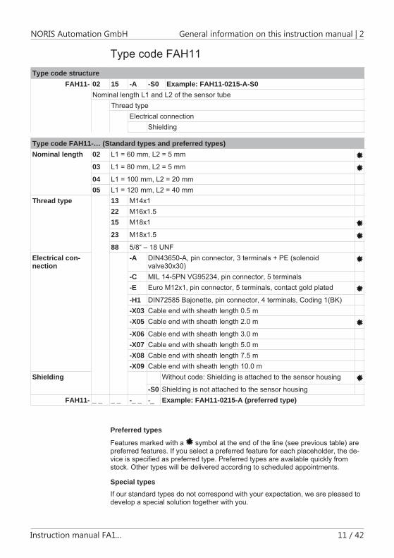
Type code FAH11Type code structure
FAH11- 02 15 -A -S0 Example: FAH11-0215-A-S0Nominal length L1 and L2 of the sensor tube
Thread typeElectrical connection
Shielding
Type code FAH11-… (Standard types and preferred types)Nominal length 02 L1 = 60 mm, L2 = 5 mm
03 L1 = 80 mm, L2 = 5 mm
04 L1 = 100 mm, L2 = 20 mm05 L1 = 120 mm, L2 = 40 mm
Thread type 13 M14x122 M16x1.515 M18x1
23 M18x1.5
88 5/8“ – 18 UNFElectrical con-nection
-A DIN43650-A, pin connector, 3 terminals + PE (solenoid valve30x30)
-C MIL 14-5PN VG95234, pin connector, 5 terminals-E Euro M12x1, pin connector, 5 terminals, contact gold plated
-H1 DIN72585 Bajonette, pin connector, 4 terminals, Coding 1(BK)-X03 Cable end with sheath length 0.5 m-X05 Cable end with sheath length 2.0 m
-X06 Cable end with sheath length 3.0 m-X07 Cable end with sheath length 5.0 m-X08 Cable end with sheath length 7.5 m-X09 Cable end with sheath length 10.0 m
Shielding Without code: Shielding is attached to the sensor housing
-S0 Shielding is not attached to the sensor housingFAH11- _ _ _ _ -_ _ -_ Example: FAH11-0215-A (preferred type)
Preferred types
Features marked with a symbol at the end of the line (see previous table) are preferred features. If you select a preferred feature for each placeholder, the de-vice is specified as preferred type. Preferred types are available quickly from stock. Other types will be delivered according to scheduled appointments.
Special typesIf our standard types do not correspond with your expectation, we are pleased to develop a special solution together with you.

2 | General information on this instruction manual NORIS Automation GmbH
12 / 42 Instruction manual FA1...
Type code FAH12Type code structure
FAH12- 02 15- -A -S0 Example: FAH12-0215-A-S0Nominal length L1 and L2 of the sensor tube
Thread typeElectrical connection
Shielding
Type code FAH12-…Nominal length 02 L1 = 60 mm, L2 = 5 mm
03 L1 = 80 mm, L2 = 5 mm04 L1 = 100 mm, L2 = 20 mm05 L1 = 120 mm, L2 = 40 mm
Thread type 13 M14x122 M16x1.515 M18x123 M18x1.588 5/8“ – 18 UNF
Electrical con-nection
-A DIN43650-A, pin connector, 3 terminals + PE (solenoid valve30x30)
-C MIL 14-5PN VG95234, pin connector, 5 terminals-E Euro M12x1, pin connector, 5 terminals, contact gold plated-H1 DIN72585 Bajonette, pin connector, 4 terminals, Coding 1(BK)-X03 Cable end with sheath length 0.5 m-X05 Cable end with sheath length 2.0 m-X06 Cable end with sheath length 3.0 m-X07 Cable end with sheath length 5.0 m-X08 Cable end with sheath length 7.5 m-X09 Cable end with sheath length 10.0 m
Shielding Without code: Shielding is attached to the sensor housing-S0 Shielding is not attached to the sensor housing
FAH12- _ _ _ _ -_ _ -_ Example: FAH12-0215-A

NORIS Automation GmbH Product description | 3
Instruction manual FA1... 13 / 42
Product description
Scope of applicationSeries 11 and 12 speed sensors are mainly used in the following areas: Ship-building industry, transport technology and mechanical engineering. The sensors can be used for registering movements of any ferromagnetic components, such as
gearwheelswithvarioustoothshapes
screwheads
holes,apertures,grooves
pulsebandsonsmoothshafts(accessories)
Measuring principleSeries 11 and 12 speed sensors, Type FAH1x operate in accordance with the differential Hall principle:
Two closely spaced Hall elements are located on the sensor chip. The field of the magnet generates a constant voltage in the Hall elements. Ferromagnetic objects with an interrupted surface moving past the Hall elements cause the Hall voltage to change. When the moving part covers a Hall element and the other does not, a differential voltage is generated to provide a measuring signal. The frequency of this signal is proportional to the speed of movement (rotational speed). The differ-ence-hall-effect principle is direction sensitive.
Series 11 and 12 speed sensors, Type FAJ1x operate in accordance with the in-ductive-magnetic principle:
The measuring element consists of a sensing coil and an iron core with a perma-nent magnet mounted. Ferromagnetic objects with an interrupted surface as they pass the sensor cause the constant field of the magnet to be changed and induce a voltage in the sensing coil. The frequency of this signal is proportional to the speed of movement (rotational speed). The inductive-magnetic principle is direc-tion-insensitive.
Peculiarities and differencesThe next table shows the features and differences between the sensors of the construction type 11 and 12.
3
3.1
3.2
3.3

3 | Product description NORIS Automation GmbH
14 / 42 Instruction manual FA1...
FAH11 FAH12 Robust housing: IP66/67 Robust and high quality housing: IP68
pressure-tight and individually tested at 5 bar
Sensor tube: Brass Sensor tube: Stainless steel Measuring principle: Difference-hall-ef-fect principle
Installation mode Direction-sensitive
Measuring principle: Difference-hall-ef-fect principle
Installation mode Direction-sensitive
FAJ11 FAJ12 Robust housing: IP66/67 Robust and high quality housing: IP68
pressure-tight and individually tested at 5 bar
Sensor tube: Brass Sensor tube: Stainless Steel Measuring principle: Inductive magnetic
Installation mode Direction independent
Measuring principle: Inductive magnetic
Installation mode Direction independent
Speed sensor design
General structure
1: FAx1x Design
A Connecting plug (see connection variants)B Threaded tubeC Counter nut
3.4
3.4.1

NORIS Automation GmbH Product description | 3
Instruction manual FA1... 15 / 42
D Nut for fixationE Sensor head (measuring area)
Type series FAx11: Sensor tube: Brass Type series FAx12: Sensor tube: Stainless steel
Connection variantsSeries 11 and 12 speed sensors are available with different connections. The connection variants are defined by the type code of the appropriate sensor type. Refer to the customer drawing for your connection variant.
Standard: e. g. Euro M18x1 or cable end (see preferred types in type code).
Signal types and output levelSpeed sensors type FAx1x (e. g. FAH11, FAH12, FAJ11, FAJ12) have a square wave output signal.
2: Signal type FAx1x_Q1
Output level FAH11UHigh ≥UB-1.5V@24VDC,10mA,24°CULow ≤0.8V@24VDC,10mA,24°C
Output level FAH12UHigh ≥UB-1.5V@24VDC,10mA,24°CULow ≤0.8V@24VDC,10mA,24°C
Output level FAJ11UHigh ≥UB-1.5V@24VDC,10mA,24°CULow ≤0.8V@24VDC,10mA,24°C
Output level FAJ12UHigh ≥UB-1.5V@24VDC,10mA,24°CULow ≤0.8V@24VDC,10mA,24°C
3.4.2Information on cus-tomer-specific connec-tions
3.4.3

3 | Product description NORIS Automation GmbH
16 / 42 Instruction manual FA1...
Elementary circuit diagram
QnRi
+UB
-UB (0V)
Push-pull output stageNote: NPN- and PNP-inputs can be connected.
3.4.4

NORIS Automation GmbH Technical data | 4
Instruction manual FA1... 17 / 42
Technical data
Technical data type FAH11 (Extract)Electrical connection Supply voltage US 9...32 VDC Nominal voltage UNOM 24 VDC Current consumption IS < 10 mA (without output current PNP) Reverse voltage protection Yes Over voltage protection Yes Connection DIN 43650A, Mil14-5PN, Euro M12x1, DIN 72585
or cable end (see customer drawing) Recommended cable length < 100 m Used cable cross section 0.38 mm², shielded
Electrical output Output channels 1 Output signal Square wave signal Output stage Push-pull amplifier Galvanic separation One channel Output current (Sink) IL max. -50 mA Output PNP (Load) IL max. 50 mA Internal resistance 45Ω
Signal acquisition Measuring principle Difference-hall-effect principle Scan type Non-contacting Scan object - material Ferromagnetic materials
Tooth wheel: Module m1 to m3; tooth face > 7 mm (spur gear DIN867) ; Hole:Ø≥5mm,web≥2mm,depth≥4mm; Groove:Ø≥4mm,web≥2mm,depth≥4mm
Scan object - distance 0.2 ... 3 mm; recommended: 1.0 ± 0.5 mm Frequency range 0.2 ... 20,000 Hz
Environmental influencesOperating temperature -40...+120°C
4
4.1

4 | Technical data NORIS Automation GmbH
18 / 42 Instruction manual FA1...
Technical data type FAH12 (Extract)Electrical connection Supply voltage US 9...32 VDC Nominal voltage UNOM 24 VDC Current consumption IS < 15 mA (without output current PNP) Reverse voltage protection Yes Over voltage protection Yes Connection DIN 43650A, Mil14-5PN, Euro M12x1, DIN 72585
or cable end (see customer drawing) Recommended cable length < 100 m Used cable cross section 0.38 mm², shielded
Electrical output Output channels 1 Output signal Square wave signal Output stage Push-pull amplifier Galvanic separation One channel Output current (Sink) IL max. -50 mA Output PNP (Load) IL max. 50 mA Internal resistance 45Ω
Signal acquisition Measuring principle Difference-hall-effect principle Scan type Non-contacting Scan object - material Ferromagnetic materials
Tooth wheel: Module m1 to m3; tooth face > 7 mm (spur gear DIN867) ; Hole:Ø≥5mm,web≥2mm,depth≥4mm; Groove:Ø≥4mm,web≥2mm,depth≥4mm
Scan object - distance 0.2 ... 3 mm; recommended: 1.0 ± 0.5 mm Frequency range 0.2 ... 20,000 Hz
Environmental influences Operating temperature -40...+120°C(statusLEDnearcableconnection
upto100°C)
4.2
NORIS Automation GmbH Technical data | 4
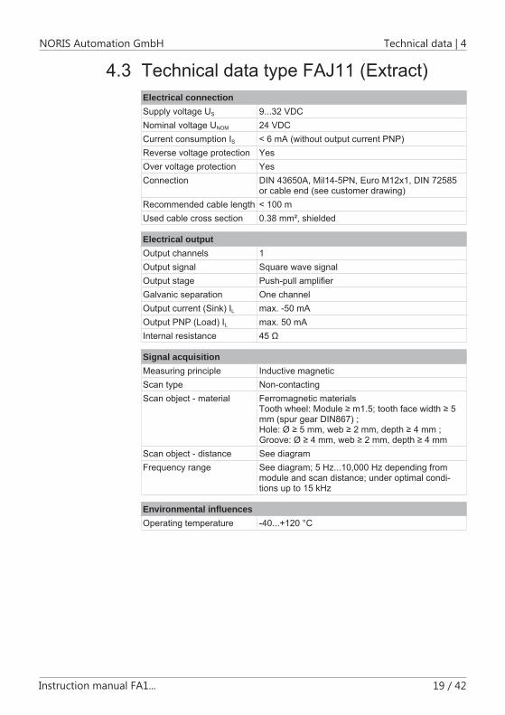
Instruction manual FA1... 19 / 42
Technical data type FAJ11 (Extract)Electrical connection Supply voltage US 9...32 VDC Nominal voltage UNOM 24 VDC Current consumption IS < 6 mA (without output current PNP) Reverse voltage protection Yes Over voltage protection Yes Connection DIN 43650A, Mil14-5PN, Euro M12x1, DIN 72585
or cable end (see customer drawing) Recommended cable length < 100 m Used cable cross section 0.38 mm², shielded
Electrical output Output channels 1 Output signal Square wave signal Output stage Push-pull amplifier Galvanic separation One channel Output current (Sink) IL max. -50 mA Output PNP (Load) IL max. 50 mA Internal resistance 45Ω
Signal acquisition Measuring principle Inductive magnetic Scan type Non-contacting Scan object - material Ferromagnetic materials
Toothwheel:Module≥m1.5;toothfacewidth≥5mm (spur gear DIN867) ; Hole:Ø≥5mm,web≥2mm,depth≥4mm; Groove:Ø≥4mm,web≥2mm,depth≥4mm
Scan object - distance See diagram Frequency range See diagram; 5 Hz...10,000 Hz depending from
module and scan distance; under optimal condi-tions up to 15 kHz
Environmental influences Operating temperature -40...+120°C
4.3
4 | Technical data NORIS Automation GmbH
20 / 42 Instruction manual FA1...
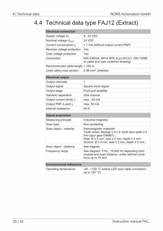
Technical data type FAJ12 (Extract)Electrical connection Supply voltage US 9...32 VDC Nominal voltage UNOM 24 VDC Current consumption IS < 7 mA (without output current PNP) Reverse voltage protection Yes Over voltage protection Yes Connection DIN 43650A, Mil14-5PN, Euro M12x1, DIN 72585
or cable end (see customer drawing) Recommended cable length < 100 m Used cable cross section 0.38 mm², shielded
Electrical output Output channels 1 Output signal Square wave signal Output stage Push-pull amplifier Galvanic separation One channel Output current (Sink) IL max. -50 mA Output PNP (Load) IL max. 50 mA Internal resistance 45Ω
Signal acquisition Measuring principle Inductive magnetic Scan type Non-contacting Scan object - material Ferromagnetic materials
Toothwheel:Module≥m1.5;toothfacewidth≥5mm (spur gear DIN867) ; Hole:Ø≥5mm,web≥2mm,depth≥4mm; Groove:Ø≥4mm,web≥2mm,depth≥4mm;
Scan object - distance See diagram Frequency range See diagram; 5 Hz...10,000 Hz depending from
module and scan distance; under optimal condi-tions up to 15 kHz
Environmental influences Operating temperature -40...+120°C(statusLEDnearcableconnection
upto100°C)
4.4
NORIS Automation GmbH Installation | 5
Instruction manual FA1... 21 / 42
Installation
Information on avoiding faults and damage
Protective Cap
Ensure that you remove the protective cap only when mounting the sensor. Otherwise the sensor may be damaged.At delivery the sensor is equipped with a protective cap to protect the meas-urement area and the electronic parts against mechanical and electrical haz-ard.
Ensure that the measurement area is not soiled.A soiled measurement area may lead to signal loss or even damage the sen-sor. Also note the recommendations in the maintenance section.
Sensor mountingWhen mounting the sensor make sure that the screw connections are tightened appropriately. Therefore note the instructions in section Installing the speed sen-sor [ 24].
Use appropriate tools and do not apply excessive force to secure the sensor.The sensor may otherwise be damaged.
Scanning distanceObserve the permissible scanning distance.
Make sure that the specified scanning distance is maintained.Signal distortion and signal loss may occur or the sensor or the scanning ob-ject may even be damaged if the scanning distance is too small. Signal dis-tortion and signal loss may also occur if the scanning distance is too great.
Connection and securing connectorsWhen installing the speed sensor, the data and information on the customer drawings always have priority over the information in this instruction manual.
5
5.1
NOTICE
NOTICE
NOTICE
NOTICE

5 | Installation NORIS Automation GmbH
22 / 42 Instruction manual FA1...
Do not touch electronical parts of the sensor (connector pins, open ca-ble end, etc.) without appropriate measures to ground your body (e. g. ESD wristband).Otherwise electrostatic discharge may damage the sensors’ electronic com-ponents.
Do not loosen the cable gland.Otherwise humidity and dust may damage the sensors’ electronic compo-nents.
The connections are to be made and connectors secured exactly as de-scribed on the technical drawings and in this manual.Incorrect wiring and incorrectly or inappropriately tightened screw connec-tions can result in signal loss or damage to the sensor or connection.
Cable installation
Make sure that the connection cable is installed correctly.Incorrectly installed connection cables can result in signal loss or damage to the sensor.
Note the minimum cable bending radius when laying the cable.Otherwise the connection cable may be damaged.
You will find further information on cable installation under Connection and cable Installation.
NOTICE
NOTICE
NOTICE
NOTICE
NOTICE
READ

NORIS Automation GmbH Installation | 5
Instruction manual FA1... 23 / 42
Preparing for installation
Dimensions
L1
L2
G1
Explanation to the illustration Please note the possible combination of L1 and L2 for the nominal length in the type code.
L1: 60, 80, 100, 120 mm L2: 5, 20, 40 mm G1: M18x1; M18x1.5; 5/8“ – 18 UNF
Checking the scanning object
To ensure trouble-free operation, the scanning object must not be dam-aged.Damaged scanning objects can result in signal distortion, signal loss or even damage to the sensor.
Make sure that the scanning object is in perfect condition.
A. Check that the scanning object is undamaged (e.g. no scratches, material unevenness, etc.).
Ifthisisnotthecase,youmustfirstrectifythesefaultsbeforeyoucontinuewiththeinstallationofthesensor.
Checking the installation holesCheck the hole before you install the sensor.
5.2
5.2.1
5.2.2
NOTICE
5.2.3

5 | Installation NORIS Automation GmbH
24 / 42 Instruction manual FA1...
A faulty hole can result in signal distortion, signal loss or even damage to the sensor.Therefore, carry out the following procedure:
A. Checktheinstallationtappedholeforthesensortube.
Theholemustbewithoutsharpedgesandtheremustbenorough-nessonthesurfaceofthehole.
B. Fitthesensorcarefullyintheinstallationholefortestingpurposes.
Thecheckisfinished.Youcannowcontinuewiththeinstallation.
Preparing tools and ressourcesFor installation prepare the following tools:
Properscrew-wrenchesaccordingtothethread
Torquewrench
Mounting speed sensors
Mounting speed sensors with inductive-magnetic principle, type FAJxxMount the sensor according to the following instructions:
Prerequisite:Thesystemisswitchedoff.
Prerequisite:Theboreholesandthescanningobjecthavebeencheckedbeforemountingthesensor.
A. Remove the thread protection.
B. Screwthesensorcarefullyintotheappropriatemountingboreholeandpo-sitionthesensorexactlytothescanningobject.
Themountingofthesensorisnotdirectionsensitive.
C. Maintain the distance to the scanning object.
D. Ifthescanningobjectisnotvisible:screwthespeedsensorclockwisetotheend stop (until the sensor touches the scanning object). NOTICE! Attention: The scanning object must stand still!!! Now screw the sensor anti-clock-wiseaccordingtoitsthreadtypetogetthecorrectscanningdistance(e.g.withthreadtypeM18x1onerotationcorrelates1mm,withthreadtypeM18x1.5onerotationcorrelates1.5mm,etc.).
Thecoverrationofsensorandscanningobjectshouldamountmin.2:3.
NOTICE
5.2.4
5.3
5.3.1
NORIS Automation GmbH Installation | 5
Instruction manual FA1... 25 / 42
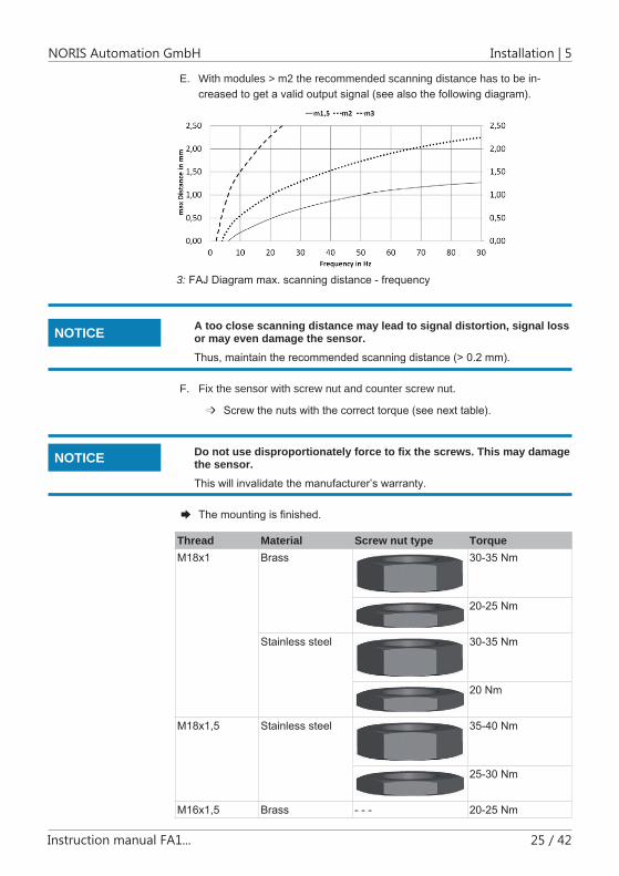
E. With modules > m2 the recommended scanning distance has to be in-creasedtogetavalidoutputsignal(seealsothefollowingdiagram).
3: FAJ Diagram max. scanning distance - frequency
A too close scanning distance may lead to signal distortion, signal loss or may even damage the sensor.Thus, maintain the recommended scanning distance (> 0.2 mm).
F. Fix the sensor with screw nut and counter screw nut.
Screwthenutswiththecorrecttorque(seenexttable).
Do not use disproportionately force to fix the screws. This may damage the sensor.This will invalidate the manufacturer’s warranty.
Themountingisfinished.
Thread Material Screw nut type TorqueM18x1 Brass 30-35 Nm
20-25 Nm
Stainless steel 30-35 Nm
20 Nm
M18x1,5 Stainless steel 35-40 Nm
25-30 Nm
M16x1,5 Brass - - - 20-25 Nm
NOTICE
NOTICE

5 | Installation NORIS Automation GmbH
26 / 42 Instruction manual FA1...
Thread Material Screw nut type TorqueM14x1 Brass - - - 20-25 NmM14x1,5 Stainless steel - - - 30-35 Nm5/8“-18UNF Brass - - - 25-30 Nm

NORIS Automation GmbH Installation | 5
Instruction manual FA1... 27 / 42
Mounting speed sensors with differential Hall principle, type FAHxxMount the sensor according to the following instructions:
Prerequisite:Thesystemisswitchedoff.
Prerequisite:Theboreholesandthescanningobjecthavebeencheckedbeforemountingthesensor.
A. Remove the thread protection.
B. Screwthesensorcarefullyintotheappropriatemountingboreholeandpo-sitionthesensorexactlytothescanningobject.
C. Maintain the recommended distance to the scanning object (see Section Technical Data) [ 17].
A too close scanning distance may lead to signal distortion, signal loss or may even damage the sensor.Thus, maintain the recommended scanning distance (> 0.2 mm).
D. Ifthescanningobjectisnotvisible:screwthespeedsensorclockwisetotheend stop (until the sensor touches the scanning object). NOTICE! Attention: The scanning object must stand still!!! Now screw the sensor anti-clock-wiseaccordingtoitsthreadtypetogetthecorrectscanningdistance(e.g.withthreadtypeM18x1onerotationcorrelates1mm,withthreadtypeM18x1.5onerotationcorrelates1.5mm,etc.).
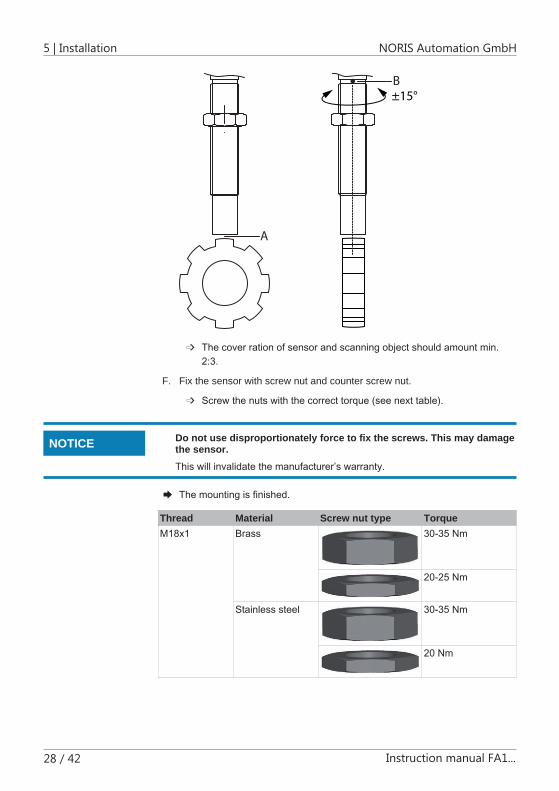
E. Themountingofthissensortypeisdirectionsensitive.Notethepositionofthe marking. Now screw the sensor clockwise or anti-clockwise (note the shortestscrewdirection)thatthemarkingofthesensorispositionedindi-rectionofrotationofthescanningobject(seenextFig.,Pos.B).
5.3.2
NOTICE
5 | Installation NORIS Automation GmbH
28 / 42 Instruction manual FA1...
A
±15°B
Thecoverrationofsensorandscanningobjectshouldamountmin.2:3.
F. Fix the sensor with screw nut and counter screw nut.
Screwthenutswiththecorrecttorque(seenexttable).
Do not use disproportionately force to fix the screws. This may damage the sensor.This will invalidate the manufacturer’s warranty.
Themountingisfinished.
Thread Material Screw nut type TorqueM18x1 Brass 30-35 Nm
20-25 Nm
Stainless steel 30-35 Nm
20 Nm
NOTICE

NORIS Automation GmbH Installation | 5
Instruction manual FA1... 29 / 42
Thread Material Screw nut type TorqueM18x1,5 Stainless steel 35-40 Nm
25-30 Nm
M16x1,5 Brass - - - 20-25 NmM14x1 Brass - - - 20-25 NmM14x1,5 Stainless steel - - - 30-35 Nm5/8“-18UNF Brass - - - 25-30 Nm
Connection and cable laying
Connection conceptIn general: The connection concepts mentioned in this section are recommenda-tions from the manufacturer. Variations for the individual application make quite sense and have to be discussed individually according to local environmental conditions. Thus, each connection concept can only be a reasonable compromise for the current conditions of the application.
Connection concept for strong electromagnetic fieldsThe signal inputs and the supply voltage of the sensor and the processing elec-tronic are galvanically isolated. The connections must be shielded to an adequate extent and conduct well.
+
Klemmkasten Elektronik /Terminal box electronics
Klemmkasten Motor /Terminal box motor
Elektronik /Electonics
+UB
Q1
0 VSchirmung / Shielding
-
+
-
Galvanisch getrennt / Galvanically isolated
4: Concept with connected shielding at both sides, type FAx1x
5.4
5.4.1
5.4.1.1

5 | Installation NORIS Automation GmbH
30 / 42 Instruction manual FA1...
Connection concept for weak electromagnetic fieldsThe signal inputs and the supply voltage of the sensor and the processing elec-tronic are not galvanically isolated. The shielding is not consistent and not con-nected to the sensor. This connection type has to be ordered separately (see type code [ 9]).
+
Klemmkasten Elektronik /Terminal box electronics
Schirmung / Shielding
Klemmkasten Motor /Terminal box motor
Elektronik /Electonics
+UB
Q1
0 V
Schirmung Shielding
-
5: Concept with connected shielding at one side, type FAx1x…-S0
Important information on connection and cable installation
Refer to the information on the customer drawings as well as the infor-mation and technical data on the corresponding sensor type as provid-ed in this instruction manual. The connection instructions provided in this section apply to speed sensors types mentioned in the Section “Scope of Application”. Make sure your body is correctly earthed (!electrostatic discharge!) before you touch the sensor connections.The cabling, connector or the sensor may otherwise be damaged.
Sensorsmustbeconnectedtothesystemwithnointerruptions.
Theconnectionsmustbeshieldedtoanadequateextentandconductwell.
Unshieldedwireshavetobekeptasshortaspossible.
Cableconnectionsmustbeuninterrupted,i.e.noterminalsbetweensensorand system.
Cableconnectionsmustbedirect,i.e.shortestroutewithoutcableloops.
Shieldedcablesmustbeused,asspecifiedinthecorrespondingtechnicaldrawings (see technical drawing for sensor).
Maintaintheminimumbendingradiustoavoiddamagingtheconnectingca-bles.
Observethemaximumpermissiblecablelength.
5.4.1.2
5.4.2
NOTICE
NORIS Automation GmbH Installation | 5
Instruction manual FA1... 31 / 42
Donotinstallthecableinthevicinityofelectromagneticfieldsorpowerlines. Signal and control lines have to be laid separately from each other to avoid coupling tracks (optimum is 20 cm or more). If the local separation of sensor and motor lines is not possible, then a plate or a metal tube has to be used for separation.
Inthecabinetthelineshastobelaidnearthecabinethousing(earth)oronthe mounting plates to avoid crosstalk of the signals.
Avoidtension,pressureandtorsionstressonthecables.
Makesurethatnosharp-edgedobjectscancomeincontactwiththecon-nection cables.
Extensivecableshieldingisrequired.
Thespeedsensorisalwaysapartofthemotorormachineunit.Thereforemake sure that the equipotential bonding or the sensor is part of the overall shielding concept.
Makesurethatnocompensatingcurrentflowsviathecableshieldingduetothe potential differences between the motor/machine and electrical ground connections. Therefore take suitable precautions, e. g. equipotential bond-ing lines with large cable cross section (minimum 10 mm2). Note that the shielding can be placed several times. Also in the switchgear cabinet it can be connected several times with the cabinet housing.
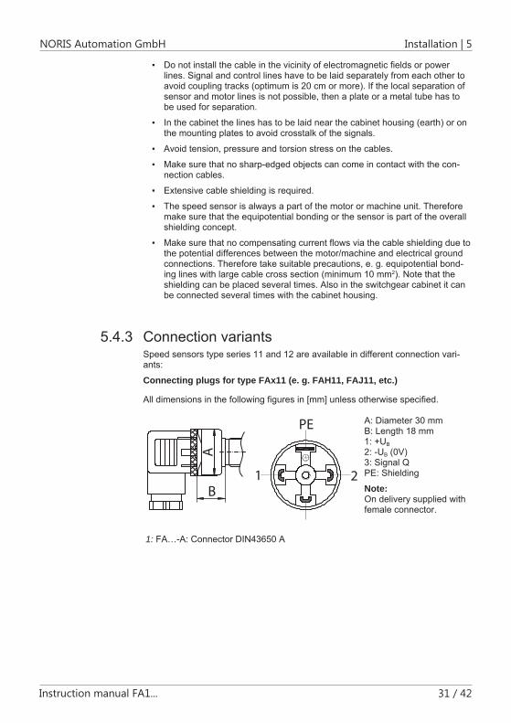
Connection variantsSpeed sensors type series 11 and 12 are available in different connection vari-ants:
Connecting plugs for type FAx11 (e. g. FAH11, FAJ11, etc.)
All dimensions in the following figures in [mm] unless otherwise specified.
A
B
PE
1 2
3
A: Diameter 30 mm B: Length 18 mm 1: +UB 2: -UB (0V) 3: Signal Q PE: Shielding
Note: On delivery supplied with female connector.
1: FA…-A: Connector DIN43650 A
5.4.3

5 | Installation NORIS Automation GmbH
32 / 42 Instruction manual FA1...
A
B
1
2
34
5
6A: Diameter 29 mm B: Length 26 mm 1: Shielding 2: -UB (0V) 3: Signal Q 4: Signal Q 5: +UB 6: Coding nib
Note: On delivery without any female connector (acces-sories set ZL4-1A)
2: FA…-C: Connector MIL 14-5PNA
B
6
3
5
1
2
4Optionally with degree of protection IP69K
A: Diameter 18 mm B: Length 16 mm 1: +UB 2: not used 3: -UB (0V) 4: Signal Q 5: Shielding 6: Coding nib
Note: On delivery without any female connector (acces-sories set ZL4-2A)
3: FA…-E: Connector Euro M12x1
A
B
4
2
1
3
5 A: Diameter 29 mm B: Length 26 mm 1: +UB 2: -UB (0V) 3: Signal Q 4: Shielding 5: Coding nib
Note: On delivery without any female connector (acces-sories set ZL4-5)
4: FA…-H: Connector DIN72585 Bajonette
AB
C D
A: Approx. 40 mm B: 80 ± 10 mm C: Ø 5 ± 0.5 mm D: 3 x 0.38 mm2 D1: Approx. 18 mm K1: Cable sheath ± 5 %
Brown: +UB Green: -UB (0V) White: Signal Q Shielding
5: FA…-X: Cable end
Connecting plugs for type FAx12 (e. g. FAH12, FAJ12)
All dimensions in the following figures in [mm] unless otherwise specified.

NORIS Automation GmbH Installation | 5
Instruction manual FA1... 33 / 42
C
A
B
PE
1 2
3
A: Diameter 30 mm B: Length 18 mm C: Status LED 1: +UB 2: -UB (0V) 3: Signal Q PE: Shielding
Note: On delivery supplied with female connector.
6: FA…-A: Connector DIN43650 AA
B
C 1
2
34
5
6A: Diameter 29 mm B: Length 26 mm C: Status LED 1: Shielding 2: -UB (0V) 3: Signal Q 4: Signal Q 5: +UB 6: Coding nib
Note: On delivery without any female connector (acces-sories set ZL4-1A).
7: FA…-C: Connector MIL 14-5PN
B
C
A
6
3
5
1
2
4Optionally with degree of protection IP69K
A: Diameter 18 mm B: Length 16 mm C: Status LED 1: +UB 2: not used 3: -UB (0V) 4: Signal Q 5: Shielding 6: Coding nib
Note: On delivery without any female connector (acces-sories set ZL4-2A)
8: FA…-E: Connector Euro M12x1
A
B
C4
2
1
3
5 A: Diameter 29 mm B: Length 26 mm C: Status LED 1: +UB 2: not used 3: -UB (0V) 4: Signal Q 5: Shielding 6: Coding nib
Note: On delivery without any female connector (acces-sories set ZL4-5)
5 | Installation NORIS Automation GmbH
34 / 42 Instruction manual FA1...
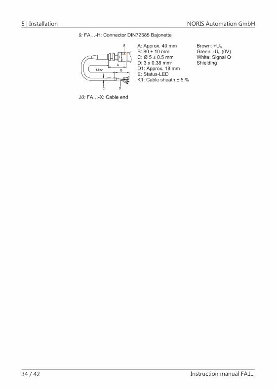
9: FA…-H: Connector DIN72585 Bajonette
AB
C
E
D
A: Approx. 40 mm B: 80 ± 10 mm C: Ø 5 ± 0.5 mm D: 3 x 0.38 mm2 D1: Approx. 18 mm E: Status-LED K1: Cable sheath ± 5 %
Brown: +UB Green: -UB (0V) White: Signal Q Shielding
10: FA…-X: Cable end

NORIS Automation GmbH Commissioning | 6
Instruction manual FA1... 35 / 42
Commissioning
Tools and equipmentHave the following tools and equipment ready for commissioning: Multimeter
2-channeloscilloscope
Make sure that the tools and equipment are in perfect working order.Otherwise the results of the measurements described below may be falsified.
Checking the operating voltageYou require the following tools and equipment:
Multimeter
Check that the operating voltage Unominal corresponds to specifications:
6: Checking operating voltage
A. Switchtothemeasuringrangefordirectvoltage.
B. Connect multimeter [+] to sensor [+] and multimeter [-] to sensor [-].
C. Switch on the operating voltage.
Result:ThemultimetershowsUnominal
Result:Unominaliswithinthepredefinedtolerance(seeTechnicalData)
Payattentiontoreversepolarity
6
6.1
NOTICE
6.2

6 | Commissioning NORIS Automation GmbH
36 / 42 Instruction manual FA1...
Checking the power consumptionYou require the following tools and equipment:
Multimeter
Simulator(load)
Check whether the power consumption IB is within the predefined tolerance:
7: Checking power consumption
Prerequisite:Yousimulatetheloadforthismeasurement.
A. Switch the measuring range to direct current.
B. Connectthemultimeterinseriesinthepowersupplyline[+].
C. Setto200mA,itmaybenecessarytoreducetherange.
Result:PowerconsumptionIBiswithinthepredefinedtolerance(seeTech-nicalData)
Checking operationYou require the following tools and equipment:
Oscilloscope
Check whether the output signal is a perfect square wave signal:
A. Connect oscilloscope [-] to sensor [-].
B. Connect oscilloscope [+] to sensor [Q].
C. Performthismeasurementwithoutandwiththeelectronicevaluatorcon-nected.
Result:Theoutputsignalisinbothcasesadistinctsquarewavesignalwithnointerference
6.3
6.4

NORIS Automation GmbH Commissioning | 6
Instruction manual FA1... 37 / 42
Pleasenote:Withoutconnectedevaluatorthepowerconsumptionisnotinthespecifiedtolerancerangewhiletestingwiththeoscilloscope.Ifthesen-sor is not connected to the electronic evaluator, the outlet lines Q[..] to the negativepolemustbeterminatedwitha2.2kΩresistorinordertoachieveadistinct output signal.
Electrical interference can often be reduced by increasing or decreasing the scanning distance. Therefore observe the minimum scanning frequency.
Checking the phase angleChecking the phase angle is relevant for sensors with 2 or more output signals.
You require the following tools and equipment:
2-channeloscilloscope
Check whether the measured phase angle of the signals agrees with the specification.
A. Connect oscilloscope [-] to sensor [-].
B. Connectoscilloscopechannel[-1]tosensor[Q1].
C. Connect oscilloscope channel [+2] to sensor [Q2].
Performthismeasurementwiththeelectronicevaluatorconnected.
Result:Theoutputsignalisadistinctsquarewavesignalwithphaseshiftasspecifiedonthecustomerdrawing
Checking the shieldingYou require the following tools and equipment:
Multimeter
Check whether the volume resistance is < 2 Ω:
A. Unplugthesensorconnector.
B. Connect multimeter [-] to the sensor housing. Connect multimeter [+] to the connector shielding connection (check against customer drawing) [-].
C. Startthecontinuitycheck.
Result:Volumeresistance<2Ω
6.5
6.6

7 | Maintenance NORIS Automation GmbH
38 / 42 Instruction manual FA1...
MaintenanceSpeed sensors contain no moving parts and are therefore classified as 'mainte-nance-free devices' by the manufacturer. Nevertheless, bear in mind that speed sensors are part of a system and are therefore subject to various ambient factors (heat, cold, motor abrasion, etc.). They are therefore included in the servicing concept as part of system maintenance. Connections and cabling. their installa-tion as well as downstream processing and evaluation components in particular are to be included in the maintenance concept.
The manufacturer recommends to check the speed sensors at regular intervals as part of system maintenance. The sensors should be cleaned if soiled. If on in-spection the speed sensors is found to be damaged, replacement is recommend-ed even if the damage does not directly cause failure or signal loss. Damaged connections and cabling should also be replaced immediately. Function tests should then be carried out to ensure trouble-free operation. This preventative maintenance avoids failures and consequential damage.
7

NORIS Automation GmbH De-installation and disposal | 8
Instruction manual FA1... 39 / 42
De-installation and disposalDe-installation of sensors
If the sensor is removed for maintenance purposes, the protective cap should be replaced on the sensor head immediately after removal.The sensor may otherwise be damaged.
Disposal of defective sensorsElectric devices should not be disposed of together with normal waste. Dispose of the sensors in accordance with local requirements for electronic equipment.
8
NOTICE

9 | Troubleshooting NORIS Automation GmbH
40 / 42 Instruction manual FA1...
Troubleshooting
Recommended procedureWhen troubleshooting the system, it is essential to precisely identify the source of faults. Faults are often suspected in the wrong place. Targeted fault localisation is therefore indispensable.
A reliable method is the exclusion procedure:
1. Temporarily replace suspect components by new components.
2. Temporarily interchange signal paths in order to locate the fault. If the fault migrates, the cause of the fault can be clearly determined in most cases.
Considerations for troubleshooting
Questions that can help you to quickly limit the scope of troubleshooting1. What kind of fault is it? Is no measuring signal applied?
Is the sensor defective?
Is the signal distorted, faulty or weak?
2. Can the sensor be clearly identified as the cause of the fault (continue with Question 4) or could the fault be attributed to conditions on site or in the system, e.g. faulty cabling (continue with Question 3)?
if possible, try replacing the sensor by a new fully functional sensor to rule out the sensor as the cause of fault.
3. Is the installation and/or cabling on site OK? (If so, continue with Question 4)
Further questions concerning installation and cabling: Have you checked whether the installation is correct (correct installation di-
rection, correct scanning distance, correct screw connection, operating volt-age supply, etc.)?
Is the cabling uninterrupted (no terminal connections, etc.)?
Are the cables damaged (abraded, breaks, kinks, etc.)?
Is the shielding correct? Is the system shielding concept coherent?
Is the connector OK (e.g. no pushed-in contact pins) or the plug connection OK?
Is the connector adequately sealed?
Is the sensor head clean (no metal chips)?
4. Are there signs of mechanical damage on the sensor? If so, what kind of damage is it? (If not, continue with Question 5)
9
9.1
9.2

NORIS Automation GmbH Troubleshooting | 9
Instruction manual FA1... 41 / 42
If there is external damage on the sensor, it is recommended to replace the sensor to ensure reliable operation of the system and to avoid subsequent failure or consequential damage.
5. Have you checked the sensor technically? A simple basic function test can already provide an indication as to whether
the sensor is functioning correctly or not. Such function tests are described in this instruction manual (see Commissioning [ 35]).
Frequent causes of fault
General causes of fault Isthecorrecttypeofsensorinstalled?Isitsuitablefortherotormodule?
Dothesensoroperatingconditionsconformtothespecification(environ-mental influences, scope of application)?
Electrical causes of fault Doesthepowersourcesupplysufficientcurrent?
Isthesensorconnectedcorrectly(cablebreak,loosescrews,etc.)?
Istheloadtoohigh(outputsignalunclear)?
Isthescanningfrequencyovershotorundershot?
Mechanical causes of faultCheck rotor:
Istherotormadefromferromagneticmaterial?
Istherotoringoodworkingorder(noburrs,nodeformation,notcovered)?
Istherotorrunningcorrectly(bearingplay)?
Doestherotorhavearadialrun-outerror?
Check sensor
Isthesensorinstalledinthecorrectposition?
Isthedistancefromthesensortotherotorcorrect?
Istheresonancewithinthepredefinedtolerance(fitoflocknut)?
9.3

10 | Service NORIS Automation GmbH
42 / 42 Instruction manual FA1...
ServiceDo you have any questions or do you required help with the installation, commis-sioning or maintenance? Contact our Service representatives:
Germany & Western EuropeNORIS Automation GmbH Muggenhofer Str. 95 90429 Nürnberg Tel.: +49 911 3201 0 Fax: +49 911 3201 150 Email: [email protected] Web: www.noris-group.com
ChinaNORIS-SIBO Automation Co. Ltd. G/F, No. 8 Building South No. 2716 Pingliang Road, Yangpu Shanghai (200090) Phone: +86 21-68761180 Fax +86 21-68758808 Email: [email protected]
10