F.24 · PDF file · 2018-03-09• Bentley MX 3D design files (to TD9 and to...
23
Appendix B – Alternative Eastern Access to SLR F.24.2
Transcript of F.24 · PDF file · 2018-03-09• Bentley MX 3D design files (to TD9 and to...

Appendix B – Alternative Eastern Access to SLR
F.24.2

NO
TE
S:
1.
All d
im
en
sio
ns a
re
in m
etres u
nle
ss othe
rw
ise sta
te
d.
2.
Do no
t sca
le fro
m th
is d
ra
win
g.
©Crown copyright and database rights [2018] Ordnance Survey [AL 100049047].
You are perm
itted to use this data solely to enable you to respond to, or interact
with, the organisation that provided you w
ith the data.
You are not perm
itted to copy, sub-licence, distribute or sell any of this data to
third parties in any form
.
Filenam
e: G
:\T
RF
EN
GN
EW
\LT
P3\E
DG
1453 LA
UN
CE
ST
ON
S
LR
- A
LIG
NM
EN
T R
EV
IE
W\3 D
ES
IG
N\3-3 D
RA
WIN
GS
\3.6.2 F
EA
SIB
ILIT
Y\E
DG
145
3_C
SL_
GE
N_S
X3
468
34
_D
R_
D_0
003
.D
WG
Plo
t D
ate
: 7
M
arch 2
018
PR
OJE
CT
M
AN
AG
ER
:
SC
AL
E:
CH
EC
KE
D:
AP
PR
OV
ED
:
DR
AW
N B
Y:
RE
VIS
IO
N:
DR
AW
IN
G T
IT
LE
:
PR
OJE
CT
T
IT
LE
:
SU
IT
AB
ILIT
Y:
PR
OJE
CT
R
EF
.:
DR
AW
IN
G S
TA
TU
S:
DR
AW
IN
G N
O:
PR
OJE
CT
OR
IG
IN
AT
OR
VO
LU
ME
LO
CA
TIO
N
TY
PE
RO
LE
NU
MB
ER
--
--
--
RE
VD
AT
EN
AT
UR
E O
F R
EV
IS
IO
N
First Issu
e
RE
VIS
IO
NS
RA
DN
OR
R
OA
D
SC
OR
RIE
R
CO
RN
WA
LL
T
R16
5
EH
ww
w.co
rm
acltd
.co
.u
k 01
87
2 3
23
3
13
SO
LU
TIO
NS
© T
his draw
ing
is C
op
yrigh
t. It sh
ou
ld
n
ot be
relie
d o
n
or used
in
circum
stan
ce
s o
th
er tha
n th
ose fo
r w
hich
it
wa
s origin
ally p
re
pa
re
d an
d fo
r w
hich C
orn
wall C
ou
ncil
wa
s origin
ally co
mm
issio
ned
. C
ornw
all C
ou
ncil acce
pts
no
respo
nsibility fo
r th
is d
ra
wing
to an
y pa
rty o
th
er th
an
th
e pe
rson
(s) b
y w
ho
m it w
as co
mm
issio
ned
.
||
|
||
Launceston S
LR
Alignm
ent O
ption
As S
how
n @
A
1
Int
In
t
In
tD
ate
Int
Date
ED
G1
45
3C
SL
GE
NS
X34
683
4
DR
D00
03
ED
G14
53
Fe
asibility
S3
P01
P0
1
D
R
A
F
T

Appendix B
Launceston SLR WSP Alignment and Model Design Review

Launceston SLR WSP Alignment and Model Design Review
EDG1453_RP_P0.1
CORMAC Consultancy CORMAC Western Region, Radnor Road, Scorrier, Redruth, Cornwall, TR16 5EH.


Issue & Revision Record
Revision Date Originator Checked Authorised Purpose of Issue Nature of Change
- 26.02.18 CB AO AJA First Issue -
This document has been prepared for the titled project or named part thereof and should not be relied upon or used for any other project without an independent check being carried out as to its suitability and prior
written authority of Cormac Solutions Ltd being obtained. Cormac Solutions Ltd accepts no responsibility or liability for the consequences of this document being used for a purpose other than the purposes for which it was commissioned. Any person using or relying on the document for such other purposes agrees, and will by
such use or reliance be taken to confirm his agreement to indemnify Cormac Solutions Ltd for all loss or damage resulting therefrom. Cormac Solutions Ltd accepts no responsibility or liability for this document to
any party other than the person by whom it was commissioned.
Prepared by Engineering Design Group
CORMAC Solutions Ltd Head Office, Higher Trenant Road, Wadebridge, Cornwall PL27 6TW
If you would like this report in another format, please contact CORMAC Solutions Ltd Head Office Higher Trenant Road Wadebridge Cornwall PL27 6TW Tel: 01872 323 313 Email: [email protected] www.cormacltd.co.uk/

- Page Left Intentionally Blank -

Contents
1 INTRODUCTION 1
1.1 Scope 1 1.2 Need for the SLR 2
2 EXISTING INFORMATION 3
3 DESIGN STANDARDS 5
3.1 Design Speed 5 3.2 Manual for Streets 2 (MfS2) 5 3.3 Design Manual for Roads and Bridges (DMRB) 5
4 ASSESSMENT 7
4.1 Outline 7 4.2 Topography 7 4.3 Horizontal Alignment 7 4.4 Vertical Alignment 8 4.5 Earthworks 9 4.6 Junctions 10 4.7 Housing 10
5 SUMMARY AND RECOMMENDATIONS 11
5.1 SLR Alignment 11 5.2 Eastern Junction to A388 11

Drawings
Drawing Title
70028324-0101 General Arrangement Sheet 1 of 3
70028324-0102 General Arrangement Sheet 2 of 3
70028324-0103 General Arrangement Sheet 3 of 3
70028324-0700 Highway Typical Cross Section
70028324-0701 Highway Long Section Sheet 1 of 4
70028324-0702 Highway Long Section Sheet 2 of 4
70028324-0703 Highway Long Section Sheet 3 of 4
70028324-0704 Highway Long Section Sheet 4 of 4
70028324-SK004 Land Ownership
EDG1453_CSL_GEN_SX346834_DR_D_0001 Cormac Solutions Ltd Proposed Junction Arrangement

EDG1453 – Launceston SLR Design Review 1 February 2018
1 INTRODUCTION
1.1 Scope
1.1.1 CORMAC Solutions’ Engineering Design Group (EDG) were commissioned by Cornwall Council to carry out a review of the existing preliminary design for the proposed Launceston Southern Loop Road (SLR).
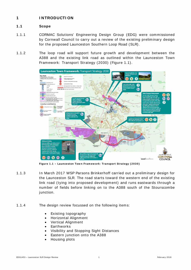
1.1.2 The loop road will support future growth and development between the A388 and the existing link road as outlined within the Launceston Town Framework: Transport Strategy (2030) (Figure 1.1).
Figure 1.1 – Launceston Town Framework: Transport Strategy (2030)
1.1.3 In March 2017 WSP Parsons Brinkerhoff carried out a preliminary design for
the Launceston SLR. The road starts toward the western end of the existing link road (tying into proposed development) and runs eastwards through a number of fields before linking on to the A388 south of the Stourscombe junction.
1.1.4 The design review focussed on the following items:
• Existing topography • Horizontal Alignment • Vertical Alignment • Earthworks • Visibility and Stopping Sight Distances • Eastern junction onto the A388 • Housing plots

EDG1453 – Launceston SLR Design Review 2 February 2018
1.2 Need for the SLR
1.2.1 The Launceston SLR was identified in the Launceston Transport Strategy, which supports the Local Plan Development Allocations for the town.
1.2.2 The transport modelling that informed the Transport Strategy identified considerable localised congestion in the town centre due to the historic road network, constrained widths and steep topography.
1.2.3 Development growth allocations for Launceston were therefore focussed to the south of the A30(T) where there is good access to the Trunk Road network.
1.2.4 Development history on land to the south of the A30(T) has focussed on individual developments that do not connect well with adjoining developments. There is limited permeability for walking, cycling and public transport.
1.2.5 The SLR will facilitate access to these developments and ensure that permeability and accessibility is maintained between developments. This is critical to enabling the transport strategy to achieve maximum benefit.
1.2.6 Further detail relating to the development of the Launceston Transport Strategy is included in the ‘Launceston Transport Strategy Development’ document, published by Cornwall Council in May 2017.

EDG1453 – Launceston SLR Design Review 3 February 2018
2 EXISTING INFORMATION
2.1.1 Cornwall Council provided the following information produced by WSP Parsons Brinkerhoff in March 2017:
• Site photographs • Existing topographical survey • Bentley MX 3D design files (to TD9 and to Manual for Streets 2
(MfS2)) • Autodesk AutoCAD 2D design drawings • Health and safety documents • Associated historic planning documentation
2.1.2 There are several constraints to take note of when assessing the proposed alignment.
2.1.3 The surrounding land to the south and east is designated as the Inny Valley & Lawhitton ‘Area of great landscape value’ (AGLV).
2.1.4 There are a number of small Cornish rivers and tributaries that run from North to South. They include a total of four unnamed tributaries that feed the Lowley Brook, which in turn feeds into the River Tamar. Works in relation to the ‘minor rivers’ will need consultation with the Lead Local Flood Authority (LLFA) and potentially consents will be required depending on the final scope of works.
2.1.5 As the proposed route is offline there are not many conflicts with existing utilities. However there are several locations where overhead 33kv WPD electrical lines pass over the alignment. Due to height requirements above highways it is likely that a number of alterations to the existing network will be required.
2.1.6 There are a number of land owners across the proposed routes. The land ownership sketch (Drawing Ref: 70028324-SK004) can be found in Appendix A.
2.1.7 A number of habitats have been identified through the Environmental Impact Assessment (EIA) carried out by WSP that will need to be considered when carrying out a detailed design for the scheme. It is recommended within the EIA that habitat surveys are carried out for the following (but not limited to):
• Bats • Breeding Birds • Badgers • Dormice • Otters


EDG1453 – Launceston SLR Design Review 5 February 2018
3 DESIGN STANDARDS
3.1 Design Speed
3.1.1 As the design will be providing a road for housing it is deemed to be acceptable to classify the alignment as a street. The client proposed design speed is set as 30mph (48kph).
3.1.2 It is noted that designing for higher design speeds will create an environment where drivers will tend to travel faster and as a result the design speeds should be kept at an appropriate level.
3.2 Manual for Streets 2 (MfS2)
3.2.1 The Manual for Streets is intended to be used for lightly-trafficked residential streets. Manual for Streets 1 (MfS1) forms the introduction to the design of streets and built up public spaces.
3.2.2 MfS2 builds on the guidance contained within MfS1, exploring in greater detail how and where its guidance can be applied to busier streets and non-trunk roads, thus helping to fill the perceived gap in the design guidance between MfS1 and Design Manual for Roads and Bridges (DMRB).
3.2.3 This being said it shall be noted that for a number of specific design criteria such as superelevation, the DMRB is referred to as being the appropriate design criteria. Having to refer to DMRB for specific criteria of the design can create a conflict by limiting what is achievable for a safe and suitable design under the Manual for Streets guidance.
3.3 Design Manual for Roads and Bridges (DMRB)
3.3.1 The DMRB provides advice and sets standards. Its intended purpose is for motorways and all-purpose trunk roads. It may also be applicable in part to other roads with similar characteristics. Where it is applied to local roads, it is for the local highway authority to decide on the extent to which these documents are appropriate in any given situation – GD01/15 (1.8).
3.3.2 While the requirements given in the DMRB may be used by local highway authorities, such authorities should ensure that their application to local roads does not increase safety risk, result in poor value for money, or have an unacceptable impact on the environment – GD01/15 (1.9).
3.3.3 MfS2 refers to the DMRB (TD9/93) for a number of specific design criteria. DMRB Volume 6 1 TD9/93 is the Design manual for Road Geometry: Highway Link Design.

EDG1453 – Launceston SLR Design Review 6 February 2018

EDG1453 – Launceston SLR Design Review 7 February 2018
4 ASSESSMENT
4.1 Outline
4.1.1 The client aspiration was to carry out an assessment of the existing WSP design to assess its viability, review standards against MfS2, highlight where potential issues may arise and identify where there is scope for improvements.
4.2 Topography
4.2.1 Using Autodesk Civil 3D the 3D topographical survey was merged with the
LiDAR data in order to produce a detailed ground model. The topographical survey was taken throughout the proposed loop road ‘corridor’ and therefore provided a more accurate surface than using solely LiDAR data.
4.2.2 This ground model was converted to contours and provided the detailed ground model for carrying out the assessment of the WSP design.
4.2.3 There are a number of features within the ground model that should be noted. To the east there is a depression striking in a North-South direction across the available land. The depression is approximately 13m in level difference across a 100m length down to 126mAOD. This will create a significant feature when designing the vertical geometry due to having a natural gradient of near to 14%.
4.2.4 The land immediately to the south-east of the existing industrial development shows a steep incline up to a height of 157mAOD. This high is located at the tightest point on the corridor within the available land and therefore is unavoidable.
4.2.5 The highest topographical point of the land within the corridor then falls to the east on a steep gradient down to a level of 114mAOD. This low point strikes North West – South East and again cuts through the entire designation of available land for the proposed loop road.
4.3 Horizontal Alignment
4.3.1 The route being assessed was produced by WSP in March 2017 and, as out
review has established, is already designed to Manual for streets standards with a design speed of 30mph (48kph).
4.3.2 The alignment ties into proposed development to the west and runs eastwards below the existing industrial units.
EDG1453 – Launceston SLR Design Review 8 February 2018
4.3.3 The WSP alignment follows the contours of the topography which in turn reduces the amount of cut required. As mentioned in sections 4.1.1 – 4.1.5 above there are a number of depressions in which minor unnamed tributaries run. These depressions cannot be avoided as they strike North – South across the extents of the available corridor. As a result there will be large areas of fill.
4.3.4 The location of the alignment was modelled in Civil 3D by Cormac Solutions Ltd and any change to the horizontal alignment was found to significantly alter the quantity of earthworks required as well as the footprint.
4.3.5 Curve radii range from 43m to 200m in line with MfS2 minimum curve radii criteria Table 8.1.
4.3.6 Due to low flows there is potential for removing the two roundabouts at Ch.520 and Ch.970 in place of simple T Junctions (Refer to 4.1.24).
4.3.7 Whilst the proposed alignment has been designed to maximise the land parcels for the housing developments to the east; it shall be noted that the proposed route cuts across fields. In some circumstances (Ch.0-700) this results in un-suitable land parcels and may be cause conflict with land owners.
4.4 Vertical Alignment
4.4.1 The vertical alignment contains maximum gradients of 8% as per MfS2.
4.4.2 Cycle routes shall be at 3% grade as per MfS2, however, this is not feasible for the whole route. Within MfS2 there is guidance that over short distances the gradient can be increased to 5% and in some circumstances 7% may be used. The WSP profile design does show sections of straights with a maximum gradient of 7.5%. However due to the topography of the area it is deemed to be unavoidable with the assembly proposed. In order to address this issue there may be leeway for taking the shared use path / footway offline so as to reduce gradients. This can be done by zig-zag cycle paths to climb the gradient however this would significantly increase the footprint and the earth works required.
4.4.3 MfS2 also notes that 8% shall be regarded as the maximum a manual wheelchair user can negotiate. This has been achieved with the WSP design.

EDG1453 – Launceston SLR Design Review 9 February 2018
4.4.4 Vertical curvature is described within section 8.5 of MfS2. The WSP design has K values ranging between 5 and 20. As the design speed is less than 50kph it is expected that drivers will reduce speed in response to changes of the alignment. MfS2 dictates that the SSD should be the basis of design. Whilst the Sag Curve is not dictated by DMRB it should be referred to for reference. TD9/93 states that for a 50kph design speed (>30mph) sag curves should have an absolute minimum K value of 9. However, TD 40/94 table 6.1 allows minimum sag curve K of 3.2. This therefore indicates that a sag curve K of 5 would be acceptable for the comfort of the driver at 48kph. The WSP design is deemed to be acceptable and fits within the requirements outlined in MfS2 based on SSD and driver comfort for the 48kph design speed.
4.5 Earthworks
4.5.1 Due to the complex topography of the designated corridor for the alignment
it is expected that there shall be significant quantities of earthworks.
4.5.2 The WSP design minimises the footprint of the earth works by designing to the contours (horizontal alignment) and by fitting a best fit profile (vertical alignment) that accords with the guidance of the MfS2.
4.5.3 A result of the best fit line is that there is minimal additional cut required for the design. However due to the four depressions containing minor tributaries there will be a significant quantity of fill. It should also be noted that culverts will be required in these areas of fill so as to not adversely affect the watercourse.
4.5.4 The result of the cut fill balance calculation highlights that the WSP design has a fill deficit of 58,000m3 (bulk factor of 1).
4.5.5 Cormac Solutions Ltd carried out a cut-fill analysis by altering the vertical profile in order to balance the ratio of cut to fill. In order to achieve a perfect balance the crest of the higher ground would need to be flattened off and this would result in a total cut quantity of 230,000m3 and a fill quantity of 230,000m3.
4.5.6 When adjusting the horizontal alignment it was noted that it results in the profile being taken off the best path to suit the contour ground model. This in turn creates a significantly larger area for earthworks and thus reduces the available land parcel space assigned for the housing development.
4.5.7 Cut and fill quantities for the housing development works are currently unknown however early indications from the ground model would suggest that there will likely be a large some cutting works required. This could help to offset a proportion of the 58,000m3 imported fill required for the WSP design if construction timescales allowed.

EDG1453 – Launceston SLR Design Review 10 February 2018
4.6 Junctions
4.6.1 The design provided by WSP contains roundabouts at Ch.520 and Ch.970.
Traffic modelling of the Landlake Road roundabout shows low predicted flows. It therefore can be suggested that the Landlake Road junction and the Hurdon Road junctions be designed as simple Major/Minor T-Junction. As the road will be designed as a 30mph the stopping sight distance (SSD) required by MfS2 of 43m can be achieved at both locations.
4.6.2 The WSP design has a four arm roundabout on the A388 on the eastern side of the scheme. The modelling data predicts low flows traffic exiting the loop road and the opposite arm towards Stourscombe.
4.6.3 The A388 is a national speed limit road lined with Cornish hedges (no verge space) and this combined with the geometry results in poor visibility at all points along the eastern end of the corridor. The road geometry in its current form is not appropriate for a ghost island T junction due to the lack of SSD for the A338 (215m for 100kph design speed). The verge clearance required to create an envelope of visibility large enough to meet design standards would take up a large proportion of the land designated for housing development.
4.6.4 It is there for thought that a roundabout is deemed to be the most appropriate junction for the road as the road geometry on the A388 can be altered in order to allow sufficient stopping sight distance.
4.6.5 It is also highly recommended that the speed limit be reviewed on the A388 between the Tavistock Road roundabout eastwards to approximately 300m south beyond the proposed roundabout.
4.7 Housing
4.7.1 There is no known detailed design information regarding the proposed land parcels for the housing developments. However the WSP design maximises the available land for housing development. The design to the east hugs the southern boundary close to the border with the AGLV, and then heads up north-eastwards to join the A388. This creates enough room to allow housing development on both the northern and southern sides of the alignment.

EDG1453 – Launceston SLR Design Review 11 February 2018
5 SUMMARY AND RECOMMENDATIONS
5.1 SLR Alignment
5.1.1 No change in horizontal alignment is recommended following a review on the WSP model. Drawing EDG1453_CSL_GEN_SX346834_DR_D_0001 shows a slight change in alignment from Ch.2100 in order to tie into the proposed CSL roundabout design.
5.1.2 No change in vertical alignment is recommended following the review of the 3D profile sections.
5.1.3 The layout of the Landlake Road roundabout and the Hurdon Road roundabout should be reviewed at the detailed design stage, as a simple T junction may be the most suitable and cost effective junction for the location.
5.1.4 At the detailed design stage it may be possible to explore opportunities to take the shared use cycle path offline where gradients exceed 5% for an extended length (>100m) in order to lessen the gradient for cyclists.
5.1.5 Vehicle speed data surveys for the A388 at the proposed junction location would allow for more detailed design of the proposed junction and allow a design speed to be calculated based on the 85th percentile of traffic speed as per DMRB TA22/81 without the need to reduce the speed limit. However it is anticipated that 85th percentile speeds will exceed the required 40mph.
5.2 Eastern Junction to A388
5.2.1 Due to the nature of the A388 and current vehicle speeds for the road it is recommended that the only suitable junction for this location is the roundabout.
5.2.2 Previous developer proposals to date are out of keeping for the area and due to the rural approach from the south and the signalised junction is not a feature that would be anticipated to be encountered by drivers on such a road.
5.2.3 Developer proposals presented to Cormac Solutions Ltd also do not meet the requirements of the forward visibility and stopping sight distance.
5.2.4 The WSP Alignment for the roundabout on to the A388 does not achieve the required visibility of 215m for the 100kph design speed.
5.2.5 Due to the location on the junction and the existing speed limit in place for the A388 resulting in high vehicle speeds it is not possible to achieve a junction with the required visibility. It is therefore proposed that the best action is to reduce the speed limit of the road on the approaches to 40mph. This in turn will reduce the required stopping sight distance to category 70A of 120m for 1.5 times the distance.

EDG1453 – Launceston SLR Design Review 12 February 2018
5.2.6 The WSP roundabout design meets the category 70A requirement of 120m visibility on the southern arm approach (A388) but not on the northern and eastern arms.
5.2.7 CSL carried out a remodelling exercise to relocate the roundabout in order to improve the visibility. The proposed CSL roundabout location (drawing EDG1453_CSL_GEN_SX346834_DR_D_0001) achieves the 120m visibility on both the northern and southern arms of the A388.
5.2.8 Further land take however would be required on the eastern arm in order to achieve required visibility and as with the WSP design also a departure would be required for the corner radius on the approach from the east. This has been highlighted on drawing EDG1453_CSL_GEN_SX346834_DR_D_0001. Full modelling will be carried out at detailed design stage and any potential departures will be raised.
5.2.9 The roundabout along with the change reduction in speed limit to 40mph will help to act as a speed control measure when transitioning into the 40mph on approach to Launceston.