F. Muir MASTER
19
SAN D--82-0078C DE82 006941 't:'" -- - ... . # ... . _,... • • C!J) "_yf -=:_ , 8 o .5J I o --> I .--------- DISCLAIMER ----- ---., This book was prepared as an account of work sponsored by an agency of the United States Government, NAithef the United States Government nor any aqency thereof, nor any of their employees. makes any warranty, express or implied, or assumes any legal liability or responsibility for the accuracy, completeness, or usefulness of any information, apparatus, product, or process disclosed, or represents that its use would not infringe privately owned rights. Reference herein to any specif ic commercial product, process, or service by trade name, trademark, manuf&Clurer, or otherwise, does not necessarily constitute or imply its endorsemenc. recommendation, or favoring by the United States Government or any agency thereof. The views and opinions of authors expressed herein do not necessarily state or reflect those of the United States Government or any agency thereof. _ .. -· ·-- - DOWNHOLE STEAM GENE RATION: MATERIAL STUDIES E. K. Beauchamp, L. J. Weirick, and J. F. Muir Sandia National Laboratories MASTER Albuquerque, New Mexico ABSTRACT One enhanced oil recovery tech- nique for extracting heavy crude from deep reservoirs by steam flooding involves generating steam at the bottom of an injection well. Development of a downhole steam generator that will produce steam and inject it into formations at depths greater than 2500 feet is one objective of a Department of Energy/Sandia National Laborator- ies development effort--Project ! DEEP STEAM. Extensive material I 1 studies have been performed in cup- ' 1 port of Project DEEP STEAM; current j efforts are devoted primarily to ; the selection and evaluation of I ' materials for use in downhole steam I generators. This paper presents 1 of the performance of I 1 candidate metals and refractory ceramics (combustor liners) during tests of two prototypic, high pres- sure, diesel/air co m bustion, This work supported by the U. s. , Department of Energy und er ____ _ contact, downhole steam generators. The first downhole test of such a generator provides data on the per- formance of various metals (304L, 310 and 316S stainless steels and ! plain carbon steel) exposed for I several weeks to a warm, aerated I environment. A number of 1 corros1on mechanisms acted to cause I severely degraded performance of some of the metals. Several refrac- 1 tory liner designs were evaluated I i during ground level tests of a ' ! generator having a ceramic-lined combustion chamber. Of the two refractories employed, alumina and silicon carbide, the alumina l ine rs exhibited more serious surface degradation and corrosion. 1. INTRODUCTION Efforts aimed at achieving greater energy self-sufficiency j have placed considerable em phasis on the development of alternative energy sources. Because of the time scales involved, however, these are not expected to ... significantly m .. ...... .. , 10H OF THIS oocuMr 1 T 1s !Jr; L::m·c
Transcript of F. Muir MASTER

SAND--82-0078C
DE82 006941
't:'" - -
Dr;,.-~ ... . # ... . _,... • •
C!J) "_yf-=:_, 8 ~ o .5J I o --> ~ I
.---------DISCLAIMER --------.,
This book was prepared as an account of work sponsored by an agency of the United States Government, NAithef the United States Government nor any aqency thereof, nor any of their employees. makes any warranty, express or implied, or assumes any legal liability or responsibility for the accuracy, completeness, or usefulness of any information, apparatus, product, or process disclosed, or represents that its use would not infringe privately owned rights. Reference herein to any specif ic commercial product, process, or service by trade name, trademark, manuf&Clurer, or otherwise, does not necessarily constitute or imply its endorsemenc. recommendation, or favoring by the United States Government or any agency thereof. The views and opinions of authors expressed herein do not necessarily state or reflect those of the United States Government or any agency thereof.
_ .. -· ·-- -DOWNHOLE STEAM GENERATION: MATERIAL STUDIES
E. K. Beauchamp, L. J. Weirick, and J. F. Muir Sandia National Laboratories
MASTER Albuquerque, New Mexico
ABSTRACT
One enhanced oil recovery tech
nique for extracting heavy crude
from deep reservoirs by steam
flooding involves generating steam
at the bottom of an injection well.
Development of a downhole steam
generator that will produce steam
and inject it into formations at
depths greater than 2500 feet is
one objective of a Department of
Energy/Sandia National Laborator-
ies development effort--Project
! DEEP STEAM. Extensive material I
1 studies have been performed in cup-' 1 port of Project DEEP STEAM; current
j efforts are devoted primarily to
; the selection and evaluation of I
' materials for use in downhole steam
I generators. This paper presents
1 obse~ations of the performance of I 1 candidate metals and refractory
ceramics (combustor liners) during
tests of two prototypic, high pres
sure, diesel/air combustion, dire~t
This work supported by the U. s. ,Department of Energy unde r ~nntrRrt
l~~:.- DE-AC~6-76DP00_~8~-· ____ _
contact, downhole steam generators.
The first downhole test of such a
generator provides data on the per
formance of various metals (304L,
310 and 316S stainless steels and
! plain carbon steel) exposed for
I several weeks to a warm, aerated
I saltwa~er environment. A number of
1 corros1on mechanisms acted to cause
I
severely degraded performance of
some of the metals. Several refrac-
1 tory liner designs were evaluated I i during ground level tests of a
'!generator having a ceramic-lined
combustion chamber. Of the two
refractories employed, alumina and
silicon carbide, the alumina l ine r s
exhibited more serious surface
degradation and corrosion.
1. INTRODUCTION
Efforts aimed at achieving
greater energy self-sufficiency
j have placed considerable emphasis
on the development of alternative
energy sources. Because of the time
scales involved, however, these are
not expected to ... :.:~;,r significantly ~ m .. ........ , 10H OF THIS oocuMr 1T 1s !Jr;L::m·c

DISCLAIMER
This report was prepared as an account of work sponsored by an agency of the United States Government. Neither the United States Government nor any agency Thereof, nor any of their employees, makes any warranty, express or implied, or assumes any legal liability or responsibility for the accuracy, completeness, or usefulness of any information, apparatus, product, or process disclosed, or represents that its use would not infringe privately owned rights. Reference herein to any specific commercial product, process, or service by trade name, trademark, manufacturer, or otherwise does not necessarily constitute or imply its endorsement, recommendation, or favoring by the United States Government or any agency thereof. The views and opinions of authors expressed herein do not necessarily state or reflect those of the United States Government or any agency thereof.

DISCLAIMER
Portions of this document may be illegible in electronic image products. Images are produced from the best available original document.

""~~;: .. ~-~· r •
the energy picture in the near-term.
; . ··. ~ . :
T ~ ·, -
Activities which promise a more im
mediate contribution toward reduced
reliance on imported petroleum in
clude the discovery and exploitation
of new domestic oil fields and the
development of advanced techniques
for extracting more oil from produc
ing fields. The application of
these improved recovery techniques
is referred to as enhanced oil re-
covery (EOR).
EOR includes a variety of tech-
niques which increase the recovery
of oil above that obtained through
primary recovery (pressure driven
or pumped). These are frequently
categorized as "secondary" and
"tertiary" recovery methods. Sec
ondary recovery techniques, such as
waterflooding and immiscible gas
.,. .. , injection, are aimed at maintaining :. ; '', :- . ~
reservoir pressure at levels ade
quate to extend production beyond
the natural cut-off point. Tertiary
recovery methods fall into two gen
eral categories: 1) chemical meth
ods in which an injected fluid
(e.g., hydro-carbons, carbon diox
ide, and micellar-polymer solu
tions) mixes with the oil effecting
miscible displacement; and 2) ther
mal methods which are priQarily
aimed· at reducing the viscosity of
the oil through the addition of
heat (e.g., cyclic and continuous
stean injection and in situ combus
tion).
Project DEEP STEAM addresses the
application of a thermal EOR tech
;nique, steam injection, to the
recovery of extremely viscous, low
API* gravity crude from deep reser
voirs. The project was initiated in
1977 as part of a 5-year Department
of Energy (DOE) EOR research,
development and demonstration pro
gram. (1) The objective of Project
DEEP STEAM is to develop the tech
nology required to economically
produce heavy oil from reservoirs
at depths greater than 2500 feet
using steam injection. Two separate
areas are being addressed: -1) modi
fication of injection well comple
tions to improve thermal efficiency
(including development of thermal
packers and evaluation of insulated
injection strings), and 2) develop
ment of a downhole steam generator
that will produce steam and inject
it into the formation at depth.
Extensive material studies have
been performed in support of
Project DEEP STEAJ1. Current efforts
are devoted to the selection and
evaluation of materials for thermal
packers and downhole steam genera
tors that are capable of surviving
the severe environments encountered
during steam injection in deep
wells. These studies include both
laboratory and field type experi
ments. This paper presents obser
vations on the performance of
several downhole steam generator
,materials during separate tests of
i two prototypic steam generators.
! Corrosion results are reported for ' )various metals, including 3041, 310
*American Petroleum Institute

~-., I •
/~-·· ..
and 316S stainless steels (SS) and
plain carbon steel, exposed for
several weeks to a warm, aerated
saltwater environment during the
first downhole test of a high pres
sure, direct contact steam ·genera
tor. Also discussed is the behavior
of two refractory materials, alumi-
na (Al2o3) and silicon carbide
(SiC), exposed to the high tempera
tures of air/ diesel fuel combus
tion during ground level tests of
a high pressure, direct contact,
downhole steam generator having a
ceramic-lined combustion chamber.
2. DOWNHOLE STEAM GENERATOR
DESIGNS
Two prototypic downhole steam
generators have been designed, fab
ricated and tested as part of
Project DEEP STEAM; one by Sandia
National Laboratories and the other
by Foster-Miller Associates, Inc.,
of Waltham, Mass.(2) Both designs
are of the high pressure combustion,
direct contact type. They are
cylindrical in shape and will fit
inside a 7-inch well casing. Each
contains a combustion chamber and
a steam generation zone as illus
trated schematically in Figure 1.
An air/diesel-fuel mixture is
injected into the combustion chamber where it burns as it flows
through the chamber. Water is in
jected directly into the combustion
products leaving the chamber. Vapor
ization of the wr~tP.r. i.n the steam
generation zone produces a mixture
of steam and combustion gases (pri-
~:~~~_! __ ~.?~nd_~.£~~..:_he -~~~~-=-~t~_: ---·
exit. The Sandia designed generator
operates at firing rates between 1
and 5 MBtu/hr at pressures up to
1500 psig. The Foster-Hiller de
signed generator is intended to
operate at firing rates from 1 to
20 MBtu/hr at pressures up to 3000
psig.
One of the principal differences
between the two generators is in
the design of the combustion cham
ber (see Figure 1). The Sandia
design employs a cold-wall combus
tion chamber consisting of a water
cooled stainless steel liner, while
the Foster-Miller design contains
a longer, hot-wall combustor having
a composite ceramic liner inside a
water-cooled sleeve.
3. METAL CORROSION STUDIES
3.1 Downhole Test of the Sandia
Designed Generator
The first test of a high pres
sure combustion, direct contact
downhole steam generator to be
carried out in a deep reservoir was
performed using the Sandia designed
prototype. The test was conducted
in the Wilmington Field, California,
and was a cooperative venture among
DOE, Sandia, the City of Long Beach,
and the Long Beach Oil Development
· Company. The generator assembly
(steam generator plus instrumenta
tion package) was located just
above the packer at a vertical
depth of about 2050 feet. Following
the initial start-up in June 1981
the generator ran without interrup
tion for almost 10 days. Generator
operation during this period was
very steady; the firing rate was
approximately 2.1 MBtu/hr at a pres
sure of about 1290 psig with a
steam production rate of approxi
mately 236 bbl/d. The next five
weeks were devoted mainly to resolv
ing a variety of system control,
hardware, and operation problems
with little or no successful opera
tion of the generator. This first
unit was pulled from the well in
August 1981 for examination and
analysis prior to completing fabri
cation of the second steam genera
tor assembly. The first unit,
therefore, was exposed to the down
hole environment for a total of 50
days. The metal corrosion results
presented below are based on obser~
vations made during post-test exam
ination of the first generator
assembly.
3.2 Design Environment and
Materials
The initial material selections
for the first Sandia designed down
hole steam generator tested at Long
Beach were made on the assumption
that the only portion of the unit
which would see a combination of warm temperatures and salt water
(reservoir water) was its external
surface. The steam generator was
fabricated entirely of 310 stain
less steel~ 304L and 316S stainless .
steels were used in abundance both
within and without the unit for
fuel, air, water, caustic, and elec
trical conduit lines. Also, API
grade J55 pipe, which is essential
ly plain carbon steel, was used for ---···------ ·---·· ---- ··-·----. -· --
the air and water supply lines.
These materials were cold formed
'and welded when necessary with no
stres~ relief steps. Thus, both
.residual and applied stresses were
,prevalent in the hardware through
out the generator assembly.
3.3 Actual Environment During the
Initial Test
A short time into the first run
a teflon sealing gasket on the
packer failed, allowing access of
air to the entire external surface
of the generator assembly. In addi
tion, it is believed that two Swage
lok fittings at the top of the
.assembly leaked, allowing access of ' i saltwater to the interior of the
!instrumentation package welded to
I the top of the steam generator.
!These events caused a breach in the I 1
1
air line inside the instrumentation
1 package resulting in the interior I ·being bathed in warm, aerated .salt-
·water.
3.4 Corrosion Observations
3.4.1 General Corrosion Photo
graph 2 shows the API grade pipe
above the generator assembly after
the first run. Extensive general
corrosion of the plain carbon steel
pipe is evident. This is not un
usual since carbon steels and
aerated saltwater are not compat
ible. The interiors of the API
grade air and water supply pipes
were corroded to such an extent
that corrosion scale clogged the
·filters repeatedly. The successful
performance of the 310 and 316
stainless steels used for the

{~~~/:~·; :: i: -.. .... ;, -·
' -~.
lt'1r...!;.:;. t~ .. : (::. !'- .. ' .....
;·---
generator and instrumentation
package housings, respectively, is
encouraging.
3.4.2 Galvanic Corrosion Examples
of galvanic corrosion which
occurred on hardware within the
instrumentation package are shown
in Photographs 3 and 4. Photograph
3 shows hose clamps which were
labeled "all stainless steel" but
·which show significant attack of
- the worm screw. The strap section
:of the clamp is 3041 SS, which per-' lformed adequately. However, the
:worm screw was made from a 400
:series, martensitic stainless which !
!_was significantly attacked. The
electrochemical potential differ
:ence between the "noble" 3041 SS
'strap and the "base" 400 SS worm
screw accelerated the corrosion of
:the latter.
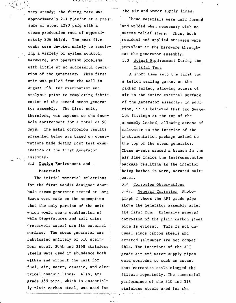
Photograph 4 shows the remains
of an aluminum spacer used as a
pipe holder and an electrical junc
jtion and ground. It was clamped to
ia steel pipe. Galvanic interaction I
jin the warm, aerated saltwater
!caused it to corrode to ·a point
/where electrical contact was broken: i ' iln this case, the potential differ-;
;ence between the aluminum and steel
itncreaied the corrooion rate of the ~ ; alumi.num. I 1
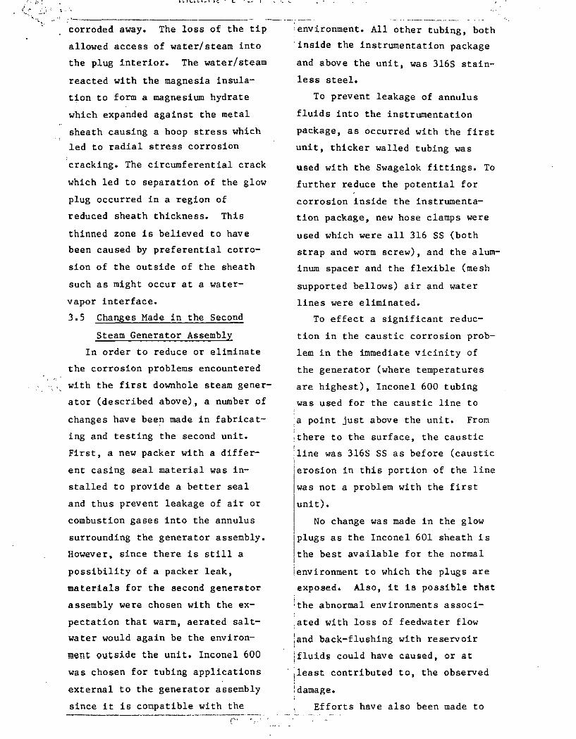
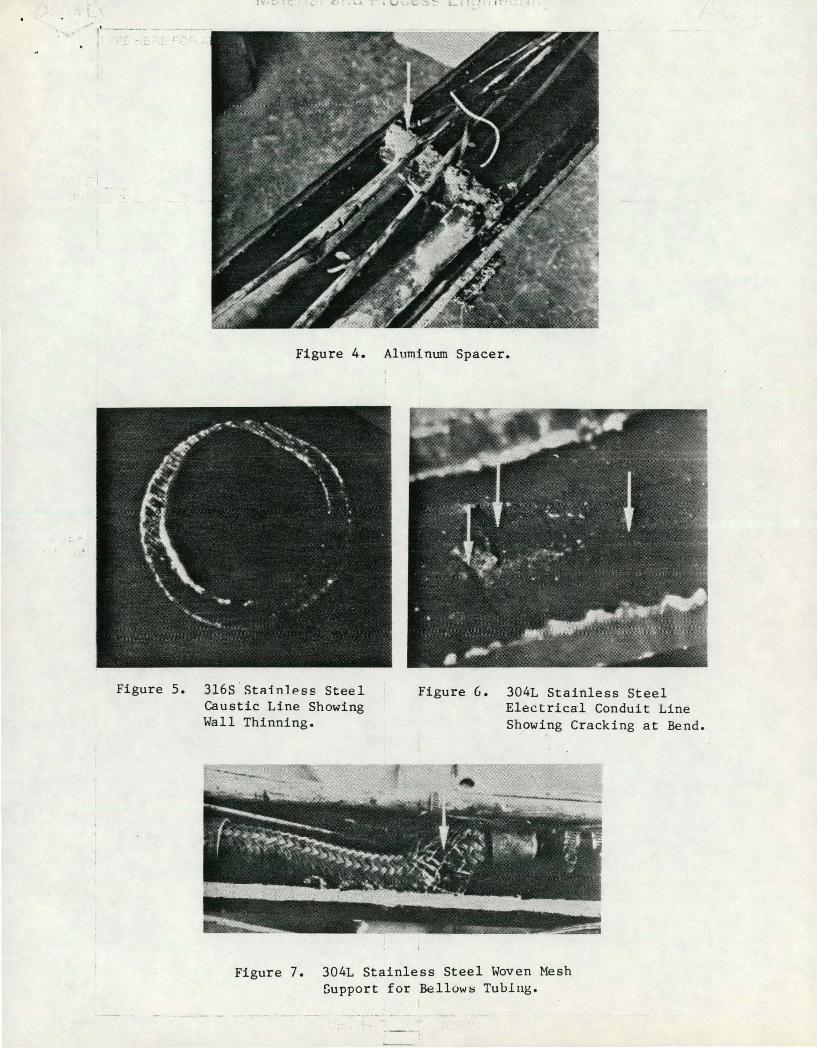
:3.4.3 Erosion-Corrosion Photograph'
·s shows an end view of a section ofi
!the 316S SS tubing used to carry
:caustic exterior to the generator.
The thinning evident in the photo-
.. . ~ ~ .• . ;
'by the caustic and erosion of the
·corrosion product by the flow.
3.4.4 Stress Corrosion Cracking
Two examples of stress corrosion
cracking of 3041 SS materials with
in the instrumentation package are
_presented in Photographs 6 and 7.
Photograph 6 is of a tubing cross
section at a bend. The residual
. stresses induced in the material,
due to cold working during bending,
·provided the driving force to cause
cracking in the warm, aerated salt
solution. Photograph 7 shows a
deteriorated woven mesh support for
· a bellows tube. The wires within
:this mesh are extensively cracked.
:There are approximately 30 frac-
tures per inch of wire in the
region of greatest deterioration.
3.4.5 Corrosion Fatigue When the
mesh support shown in Photograph 7
failed, it caused the pressure load
within the air line to transfer to
the inner stainless steel bellows.
Within a short time the bellows
cracked due to corrosion fatigue,
'a mechanism of corrosion caused by
attack of the environment coupled
with fatigue crack growth due to i
i pressure loads.
!3.4.6 Combined Corrosion Mechanisms ; i
.Photograph 8 shows three glow plugs:
the two outer plugs were uocd. in
the generator to ignite the diesel/
air mixture while the center plug
.is a new one shown for comparison.
·The used plugs failed due to a I
:combination of corrosion events. I
:First, the tip of the glow plug graph was caused by the combined
action of corrosion of the tubing I !
1 :(rnconel 601 sheath) eroded/ ' _____ j -~
".·,!.;,' .-..-j.{;~~,-;:1 ~c. l c.:: ........ (
:(; ~.-~ :, \ .. '
corroded away. The loss of the tip
allowed access of water/steam into
the plug interior. The water/steam
reacted with the magnesia insula
tion to form a magnesium hydrate
which expanded against the metal
sheath causing a hoop stress which
led to radial stress corrosion
cracking. The circumferential crack
which led to separation of the glow
plug occurred in a region of
reduced sheath thickness. This
thinned zone is believed to have
been caused by preferential corro
sion of the outside of the sheath
such as might occur at a water
vapor interface.
3.5 Changes Made in the Second
Steam Generator Assembly
In order to reduce or eliminate
the corrosion problems encountered
with the first downhole steam gener
ator (described above), a number of
changes have been made in fabricat
ing and testing the second unit.
First, a new packer with a differ
ent casing seal material was in
stalled to provide a better seal
and thus prevent leakage of air or
combustion gases into the annulus
surrounding the generator assembly.
However, since there is still a
possibility of a packer leak,
materials for the second generator
assembly were chosen with the ex
pectation that warm, aerated salt
water would again be the environ
ment outside the unit. Inconel 600
was chosen for tubing applications
external to the generator assembly
since it is conpatible with the -------- -------------- ----.
("
:environment. All other tubing, both
'inside the instrumentation package
and above the unit, was 316S stain
less steel.
To prevent leakage of annulus
fluids into the instrumentation
package, as occurred with the first
unit, thicker walled tubing was
used with the Swagelok fittings. To
further reduce the potential for
corrosion inside the instrumenta
tion package, new hose clamps were
used which were all 316 SS (both
strap and worm screw), and the alum
inum spacer and the flexible (mesh
supported bellows) air and water
lines were eliminated.
To effect a significant reduc
tion in the caustic corrosion prob
lem in the immediate vicinity of
the generator (where temperatures
are highest), Inconel 600 tubing
was used for the caustic line to
,a point just above the unit. From
;there to the surface, the caustic I
:line was 316S SS as before (caustic I ;erosion in this portion of the line
was not a problem with the first
unit).
No change was made in the glow
l
plugs as the Inconel 601 sheath is
the best available for the normal
!environment to which the plugs are
exposed. Also, it is possible that
:the abnormal environments associ
.ated with loss of feedwater flow
;and back-flushing with reservoir
ifluidi could have caused, or at
!least contributed to, the observed
!damage.
Efforts have also been made to

,s : 1··· .. ~ '-'.
;_,:.:· ~-- .. ;_ ~'\ ·, .
"'-.: · ........ ! • ----·--------"-'"""' -·-·--·--·-·---.... -_,__ ...... ----,.·-- ·-- --- ··- --- .. -· ··- -·-
!reduce general corrosion of the during steady-state operation.
l,~.~ • • --
!plain carbon steel air and water
:supply lines (both internal and
jexternal). Sodium sulfite has been I
ladded to the feedwater for chemical
'Scavenging of dissolved oxygen. In
:addition, the annulus water has
[been treated continuously with !
sodium sulfite and a filming inhib
itor. A refrigeration type air
dryer has been added to the air
supply system to further reduce the
moisture content of the compressed
air provided to the generator.
4. CERAMIC LINER PERFORMANCE
The ceramic shown schematically
as the combustion chamber liner of
the Foster-Miller steam generator
design in Figure 1 was actually
a composite structure consisting of
a sintered ceramic inner tube 3
feet long and 3 inches I.n.·with
an outer layer of either ceramic
felt or a castable ceramic. Table
1 includes sketches of the various
prototypic liners tested in the
Foster-Miller program.
The primary function of the
ceramic combustor liner is to pro
vide a thermally insulating barrier
which will permit a high tempera
ture to be maintained on the inner
surface (adjacent to the flame)
while· limiting the temperature on
the metal parts and minimizing heat
flow to the water jacket. The liner
must be able to survive the stress
es produced in rapid temperature
excursions during start-up and shut
down as well as those resulting
from radial and axial gradients > .
It
must also be thermally and chemic
ally stable in the combustor
environment.
From a thermal stability stand
point (resistance to thermal shock
and high melting point), the best
choices of commercially available
ceramics seem to be SiC and silicon
nitride (Si3N4).(3) On the other
hand, Al2o3 and zirconia (Zro2)
should be more stable chemically
than SiC and Si3N4 in the low
oxygen partial pressures that might
exist in the combustor.< 4) Not
enough was known about the com
bustor environment to validate a
selection among these candidates.
Instead, both Al2o3 and SiC, the
two materials readily available in
tubes of the proper size, were
tried in different combustor
designs.
Each of the combustor liner con
figurations was tested by Foster
Miller in a prototypic steam gener
ator that was operated inside a
pressure vessel capable of simulat
ing downhole conditions. Operating
parameters are given in Table 1.
In addition, the best performing
design, employing a SiC liner, was
operated in a 5-day test of the com
plete Foster-Miller downhole steam
generator system (Series 6). This
quasi-field test was conducted at
the DEEP STEAM test site at Sandia
National Laboratories. The genera
tor was mounted near the top of a
test well (120 feet deep) cased
with 7 inch diameter well casing.

t .
.. · r-' ----··--:--··-·~-- ------·------··-- ...................... ·- -·-
For the first 93 hours of th-e--t~s-t · · 1 stresses on the interior surface of
the firing rate was nominally 5
MBtu/hr. During the last 21 hours
this was increased to 7.5 MBtu/hr
and then to 10 MBtu/hr. The associ-
ated steam generation rates were
175-330, 430-550, and 695-725 bbl/d,
respectively. The total test time
'for this SiC liner (including Test
Series 5) was over 150 hours.
Performance of the ceramic
liners was evaluated primarily by
post-test examination of failure
;surfaces and microstructure. Frac-
tographic analysis of the failure
-surfaces permitted a determination
of the direction of local mechani
cal stresses during failure as well
as estimates of relative magnitudes.
This information was compared with
calculated stresses obtained from
. .. thermal and stress analysis of the
structures.
4.1 Alumina Combustor Liner
The first designs tested used
Norton AN498A porous alumina tubes
as liners. For Test Series 1,
Norton CA333 castable alumina was
cast between the alumina tube and
the water jacket to give rigid sup
port to the tube. No failure was
observed after the first run but,
in subsequent runs, fragments
spall~d off the inner surface of
the tube and were carried out of
the combustor. These fragments
were roughly lenticular in shape,
0.5 to 1.5 inches in diameter and
0.1 to 0.2 inch thick. The shape
suggested that failure had occurred
because of planar compressive . :- • ~·-: .= r.~ -
I
i the tube.
Examination of these spall frag
ments revealed that the alumina had
become very friable, so that it
crumbled under finger pressure. In
the Scanning Electron Microscope
(SEM), failure surfaces of the
alumina showed features like those
in Figure 9. These are apparently
growth features, probably a result
. of vapor phase transport involving
the more volatile suboxides of
Al2o3.< 5 ) In some areas, enhanced
growth features such as the whis
kers shown in Figure 10 were found.
These whiskers were almost certain
ly produced by vapor deposition.
X-ray emission analysis in the SEM
showed that these features are
essentially only alumina •
In the combustor tested in
_Series 2, the porous Norton tube
was separated from the water jacket
by a layer of Johns~Manville cera
blanket (ceramic felt) which per
mitted the tube nearly free expan-
i sion. During testing, the tube
!fractured into roughly rectangular
segments approximately two inches
on a side. Additional cracks
extended part way through these
segments. These partial cracks had
started at the inner surface of the I
'tube and extended toward the outer
'surface. Only modest force was l !required to complete these frac-1
itures and expose the failure sur-
ifaces for examination. In contrast
:with the first tube, the inner sur
·face remained hard and strong •

• f e f ,, "-' • ; ~ '
. I • :~' '•
---·~·- -----.. ·4------ ---·---·-·-··----.-....... __ ..., ________ , SEM examination of the failure
isurfaces revealed few grains with
1 surfaces characteristic of brittle
fracture. Most of these grains
~were in the region that was frac
;tured after the segment was removed
·from the combustor. Much of the i :failure surface near the inner sur-
face of the tube showed structural
features like those in Figure 9.
All the evidence--the propaga
tion of the cracks from the inner
surface toward the outer, the fact
that the incomplete cracks stayed
open after the tube had cooled down /
and the nature of the failure
surface--indicates that failure
occurred because of non-uniform
shrinkage of the alumina. The
porous alumina body sintered and
shrank, faster near the inner sur
face because of the higher tempera
tures there, giving an effect like
mud-flat cracking.
Although the types of failures
in the two Norton porous alumina
tubes were different, both were
associated with the presence of
open porosity. In the first tube,
failure occurred because of weaken
ing of the grain boundaries,
apparently a result of attack by
combustion gases through the pores.
In the second tube, the presence of
open pores provided the driving
force for sintering which fractured
the ceramic.
To eliminate the problems
associated with porosity, a high
density, high-purity McDanel
alumina tube was selected for the .. ! ~
I third prototype combustor. In an
I attempt to reduce the axial
I stresses which analysis indicated
I were high in a monolithic tube,
1 this tube was cut into axial seg-1 . ments two inches long and bonded
: into the combustor with Norton
· CA333 castable alumina. In this
combustor design, a stainless steel
sheath separated the alumina tube
and castable layer from the sur
rounding water jacket. It was
·expected that the higher compliance
of this design, compared with one
in which the ceramic was bonded
·directly to the water jacket, would
decrease thermal stress levels.
However, subsequent stress analysis i :showed that creep would probably
occur in the stainless steel sheath
in the first heating cycle, so that
tensile stresses would be generated
in cooling and in subsequent runs.
Four runs of about 0.9 hour dur
ation were made on this combustor
beginning with a low firing rate,
1.25 MBtu/hr, for the first run and
increasing incrementally to about
2.5 MBtu/hr in the final run (Test
Series 4). No cracking was ob
served after the first run. However,
after the second run some cracks
were observed, and in succeeding
runs they increased in number and
severity. During the fourth run,
some pieces of the end tubes broke
loose and were expelled from the
combustor.
Fractographic examination of
expelled fragments and others
removed from the tube after testing

....
L •.
revealed that most of the fractures
initiated at the inner surface of
the tube and propagated radially
outward. Orientation of the cracks
indicated both axial and circumfer
ential tension. Most surfaces were
blackened with carbon, indicating a -. reducing environment had been main-
tained, at least in the final run.
In some areas, at the inner surface
of the tube, a closely spaced net
work of shallow cracks ran into the
alumina. In those areas, the alum
ina was markedly weakened so that
grains and clusters of grains could
be removed from the surface. SEM
examination of the fracture sur
faces in these weakened regions
showed severe grain boundary ero
sion and some growth features like
those seen in the porous Norton
tubes (Figure 9).
On one fragment which had been
pried loose from the combustor
assembly after testing, some of the
castable ceramic remained as an
adherent layer. Crystallite morphol
ogy and Ca to Al ratio, as deter- ·
mined from X-ray emission and com
pared with observations by Givan et
al,(6) indicated crystals adjacent
to the outer surface of the McDanel
tube had been exposed to tempera
tures. of at least 2200°F, while
those 0.1 inch radially out from
that surface saw temperatures of
1450°F to 2200°F. These tempera
tures agree well with those
obtained in thermal analysis.
4.2 Silicon Carbide Liners
In the first design employing
-~ r·
. t• •
-- -; ------··- ... :SiC, a Norton CRYSTAR tube was held
·in the combustor with a layer of
1 refractory fiber felt. This tube
!fractured into irregular pieces
!during the first cycle (Test Series
'3) and fell apart in the second
cycle. A thick layer (.040 inch)
of glass (Si02 formed by oxidation
of the SiC) was found on the inner
surfaces.
The most successful Foster
Miller design featured a Carborun
dum REFRAX SiC tube bonded into a
thin-walled stainless steel liner
with Norton CA333 castable alumina
containing 25% iron powder. This
tube was examined after four cycles
of Test Series 5, again at the end
of Test Series 5, and finally at
the end of Test Series 6. In the
first examination, a few cracks
were found near the inlet and a
thin layer of glass was found on
the tube wall. At the end of Series
5, a network of cracks was visible
over the entire tube with cracks
spaced from about 1.0 inch apart at
the tube ends to 0.3 inch apart at
the center. However, except for a
few chips expelled from cracks, the
tube remained in place.
At the end of Series 6, examina
tion showed that a 2-3 inch section
of the SiC tube was missing from
the downstream end. In most of
this area the castable ceramic was
removed, and in a portion of the
area the stainless steel liner had
eroded away. The fracture surface
where the section of SiC was
removed was rough, irregular, and

.. '.> ~--)
r -----· -- - . - _r---. ----· ·-·-- ·- -·---gray-white in color suggesting that 5. SUMMARY
oxidation had weakened the grain
boundaries.
Even with the loss of the tube
end, the performance of the SiC was
clearly. much better than that of
any of the alumina tubes. Although
the SiC tube cracked extensively,
the mechanical constraint of the
castable ceramic, the stainless
steel sleeve, and probably the Si02 coating produced by oxidation, kept
it in place. Oxidation of the tube
to form Si02 glass was extensive.
However, the glass layer adhered,
maintaining a barrier against
further oxidation. There was no
evidence of spalling of the glass
layer which often occurs on SiC
heater elements when they undergo
similar thermal excursions; nor was
there evidence of substantial
erosion of the layer, which could
occur at temperatures high enough
and oxygen pressure low enough for
Sio2 to decompose to the volatile
monoxide.(?) The only real failure
occurred because the fragments at
the end were able to move axially
and separate from the tube. Some
form of axial constraint, perhaps a
metal collar, which would lock the
end of the tube in place, might
prevent that motion and substanti
ally extend the life of the tube.
Two high pressure combustion,
direct contact, downhole steam gen-
i erator designs have been fabricated
and tested in separate experiments
as part of Project DEEP STEAJ-1.
Post test observations have pro
vided information on the perform
ance of candidate metals and refrac-
tory ceramics exposed to the severe
environments encountered during
steam injection in deep wells. A
number of corrosion mechanisms
; acted on the first steam generator
tested downhole and caused severely
, degraded performance of some of the
. metals employed. These corrosion ;
: problems are understood and pre-' lventable, and the second unit to I ! be tested downhole incorporates
· changes design~d to eliminate them. 1 Alumina performed poorly as a com
' bustor liner material because of
: grain boundary attack by the com-
. bustion gases which resulted in
: loss of strength and eventual
disintegration. Although silicon
carbide tubes fractured, they gave
satisfactory performance provided
suitable mechanical constraint was
used to prevent fragments from
separating from the tube.
·-------------------;:--- -·· ·-··· "'• ~ I ·~ ,.._
~. :... ' • I ' ..

.·y_
;'·----··-··--·---· --·-·--4--·---· _R ___ _ . 6. REFERENCES
1. Dept. of Energy, "Technology Im
plementation Plan for Enhanced
Oil Recovery," Draft, June 1978.
2. Project DEEP STEAM Quarterly
Reports from Jan 1 - Mar 31,
1978 (SAND78-1023, August 1978)
through Oct 1 - Dec 31, 1980
(SAND81-1199, Sept. 1981).
3. R. N. Katz, "High Temperature
Structural Ceramics," Science
208, 841 (1980).
4. L. Y. Sadler et al, "Evaluation
of Refractory Liner Materials
for Use in Non-Slagging, High
Btu Coal-Gasifier Reactors,"
Ceramic Bull.~ (7), 705
(1979).
5. L. Brewer and A. W. Searcy,
"The Gaseous Species of the
Al-Al2o3 System," J. Am. Chern.
Soc. 21., 5308 (1951).
6. G. v. Givan et al, "Curing and
Firing High Purity Calcium
Aluminate-Bonded Tabular
Alumina Castables," Ceramic
Bull.~' (8), 710-13 (1975).
7. A. F. McLean et al, "Brittle
Materials Design, High Tempera-
ture Gas Turbine," AMMRC-CTR-
75-8, Interim Report, April
1975.
i ... ~------------·--------~- ·-· _____ .,· ... ~ ....

Table 1. Foster-Miller Ceramic Liner Configurations and Test Conditions
Total Firing Run Number
Test I Rate Pressure Time of Liner Liner Ceramic I Backing I Fabrication Series (HBtu/hr) (psig) (hr) Cycles Construction Configuration Material Material Method
1 I 1.25 I 175 1.6 6 ~'W:~ Monolithic A12o3 Castable: Cast to () :\ r-i ' . •
3" ID x 3/8" Norton Norton water wall AN498A CA333 jacket I 'l'"'t
... ... -
I I I ~i~~-'~Vbl I Monolithic I
"1 .. 2 I 1. 25 I 175 1.3 4 () -t\
A12°3 Blanket: Placed in ,, --.. 3" ID x 3/8" Norton Johns- water wall AK498A Manville jacket
cera blanket ~~;:1;-:f@J
3 1.25 175 0.9 2 ~'I~ u '.f.)\ .-.~ mt Monolithic SiC Blanket: Placed in
2-3/4" ID x Norton Johns- water 3/16" wall CRY STAR Manville jacket
cera blanket
Cast in 4 I 1.25-2.5 I 300 I 3.5 I 4 I ~~~~~t~~ I 2" cylinders Alt3 Castable: steel
3-1/8" ID x Me anel Norton sleeve 3/16" wall 998 CA333 0. 025 in.
air gap
cast- Cast 5 I 5.0 I 250-1000 I 40 I 16 I ~'t;~ ~~.~~ I Monolithic SiC able, 25% steel
3" ID X 1/2" Carborun- iron powd. sleeve wall dum Norton 0.025 in.
REFRAX 20 CA333/25 air gap 6 I 3.5-lo.o I 900-1300 I 115 I 19 I ~\~~-~1""~'t'f;f I I mesh

r· • ;. ,;·:. r.t-~~ .. - """~,r.- /.,.' ,.. - ~- - +
~- -.r-- .. ~ . ,.. . . ...
WATER WATER
t FUELAIR F1EL
~~~--~~Hl~ ~~ I
FUEL/AIR MIXTURE
' I COMBUSTION
~HAMBER
{
STAINLESS STEEL LINER
CERAMIC]. LINER
1DETAILS IN
TABLE 1
STEAM GENERATION ZONE
SANDIA DESIGN FOSTER-MILLER DESIGN
Figure 1. Schematic of Two Prototypic, High Pressure, Direct Contact, Downhole Steam Generators.
·--- ------ --

:_ ,; .
- -·-;-t
Figure 2. API Grade Pipe and Steam Generator Assembly.
Figure 3. Stainless Steel Hose Clamps.
c.r , .......
•' --' r.~
Figure 4. Aluminum Spacer.
Figure 5. 316S StRinlPss Steel Caustic Line Showing Wall Thinning.
Figure G. 304L Stainless Steel Electrical Conduit Line Showing Cracking at Bend.
Figure 7. 304L Stainless Steel Woven Mesh Support for B~llows Tuulug.

. '•
Figure 8. Glow Plug Ignitors with Inconel 601 Sheathing.
Figure 10. Whisker Growth on Failure Surface of Porous Alumina Combustor Liner. SEM Micrograph (5 ~w bar).
, __
Growth Features on Failure Surface of Porous Alumina Combustor Liner. SEM Micrograph (5 ~m bar).