F. Grasso - ecn.nl · there are several restrictions for BEM codes usage. By using full...
13
AWSM Ground and Wind Shear Effects in Aerodynamic Calculations F. Grasso ECN-E--10-016 FEBRUARY 2010
Transcript of F. Grasso - ecn.nl · there are several restrictions for BEM codes usage. By using full...
AWSM Ground and Wind Shear Effects in Aerodynamic
Calculations F. Grasso
ECN-E--10-016 FEBRUARY 2010
Abstract In order to design more advanced and efficient wind turbines, more accurate results coming from numerical predictions are mandatory. This need became more and more important in the last years due to the growth of wind turbines, especially for offshore scenarios. The diameter of a modern MW class wind turbine can easily be greater than 100m, on which the effect of wind shear and incoherent atmospheric structures on blade loads play a much more significant role. Most of the available codes are based on Blade Element Momentum (BEM) theory. The main advantage of this class of codes is the fact that they are very fast to calculate the loads and per-formance of a wind turbine. This makes BEM codes very convenient especially in the very ex-tensive wind turbine design and load calculations, but due to all the hypotheses of the theory, there are several restrictions for BEM codes usage. By using full Navier-Stokes based codes, for example, there are no limitations about the geome-try and no restrictive hypotheses related with the aerodynamics, so it is possible to perform both detailed fluid-dynamics studies and general performance-oriented analyses in very general con-ditions. The drawback is the big demand in terms of computational resources, computational time and expertise. A code, named Aerodynamic Windturbine Simulation Module (AWSM), has been developed at Energy research Centre of the Netherlands (ECN) by van Garrel [1]. The main scope was to keep the advantages of BEM codes in terms of calculation time and ease of use, but to obtain a superior quality, especially concerning wake and time dependent wake-related phenomena. The presence of the ground during the analyses, as well as the presence of a non uniform wind introduce sensitive effects in the numerical predictions. These effects regard both the response of the blade and the evolution of the wake. During UpWind project, part of the research was focused on these two effects and their inclusion in the calculations. The aim of the present report is to illustrate these two extensions and their implementation in AWSM code. Two separated sections are dedicated to describe these additions in terms of implementation, usage and numerical examples. Project information ECN project number: 7.9466.02.03
2 ECN-E--10-016
Contents
List of figures 4
1. Introduction 5
2. Ground Effect 6 2.1 Implementation of the ground effect in AWSM 6 2.2 Usage description 6 2.3 Numerical example 6
3. Wind Shear Effect 9 3.1 Implementation of the wind shear in AWSM 9 3.2 Usage description 9 3.3 Numerical example 10
4. Conclusions 13
References 13
ECN-E--10-016 3

List of figures
Figure 1 Side view of the wake. Comparison between ground (top) and no ground (bottom) conditions. ................................................................................................................. 7
Figure 2 Side view of the wake. Comparison between ground (top) and no ground (bottom) conditions. ................................................................................................................. 7
Figure 3 Front view of the wake. Comparison between ground (left) and no ground (right) conditions. ................................................................................................................. 8
Figure 4 Circulation along the blade. Comparison between ground and no ground conditions. ... 8 Figure 5 Side view of the wake. Comparison between no wind shear (top) and wind shear
(bottom) conditions. ................................................................................................ 10 Figure 6 front view of the wake. Comparison between no wind shear (left) and wind shear
(right) conditions..................................................................................................... 10 Figure 7 Front view of the wake. Tip vortex and root vortex. .................................................... 11 Figure 8 Top view of the wake. Tip vortex and root vortex. ....................................................... 11 Figure 9 Circulation along the blade. Wind shear - no wind shear comparison. ........................ 12
4 ECN-E--10-016
1. Introduction
In order to develop more advanced and efficient wind turbines, more accurate and realistic aerodynamic simulation tools are necessary. The aim of the AWSM code [1] is to have the advantages of BEM codes in terms of calculation time and easy-usage but obtain, at the same time, a superior quality, especially concerning wake and time dependent phenomena. In order to extend the versatility of AWSM, the opportunities to take into account the presence of the ground and incoming wind with large shear are added and described. The presence of the ground can sensibly modify the performance of the rotor and the response of the blades. The ground can also introduce modifications in the wake development. In the same way, the presence of large wind shear in the incoming flow introduces a spatial de-pendence in the loads along the blades. Because of the wind shear, the incoming velocity is lar-ger in the upper part of the rotor than on the lower part. This means that the response of the blade during the rotation is variable. So globally, analyses in presence of ground and wind shear effects can improve the accuracy and the realism of the numerical predictions. The next section is dedicated to describe the implementation of the ground effect. The succes-sive section is dedicated to the wind shear. In both cases, the implementation and the usage are illustrated, as well as numerical examples. The geometry used for the examples is the reference wind turbine (RWT) [2, 3] defined in UPWIND project [4].
ECN-E--10-016 5
2. Ground Effect
2.1 Implementation of the ground effect in AWSM In order to simulate the presence of the ground during the calculations, a “mirroring” approach is used. During the aerodynamic analysis, the induction in all the points, due to the other ones, is deter-mined. If the ground effect is involved in the analysis, there is an additional contribution con-nected to the fact that the ground is “virtually” taken into the problem by mirroring each “influ-encing” point. More in details, the location of each mirrored point is opposite to the original one compared to the location of the ground and the circulation is also inverted in sign. As consequence of the above mentioned approach, the calculation time is doubled with respect to calculation without ground effect. It should be also noted that, without ground effect, the hub height is not really relevant for the rotor performance itself. In presence of the ground, the hub height in the geometry file is a nec-essary parameter. In fact the actual hub height is the difference between the ground altitude and the hub altitude specified in the geometry file.
2.2 Usage description Two new variables are added to AWSM. The first one (zMirrorOn) is a flag indicating that the ground effect is active or not; the second parameter (z0) is the location, or altitude, of the ground. Both of them are assigned from the command line of AWSM at the beginning of the analysis.
variable Default type zMirrorOn No Logical z0 0. real
' Mirroring : ', zMirrorOn ' Mirror position : ', z0
2.3 Numerical example In order to evaluate the influence of the ground on AWSM results, two analyses have been per-formed. In the first one, the ground is not present; in the second one the ground is present and the hub height is 75m. In both cases, the incoming speed is uniform and equal to 8m/s.
6 ECN-E--10-016
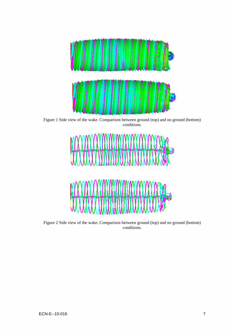
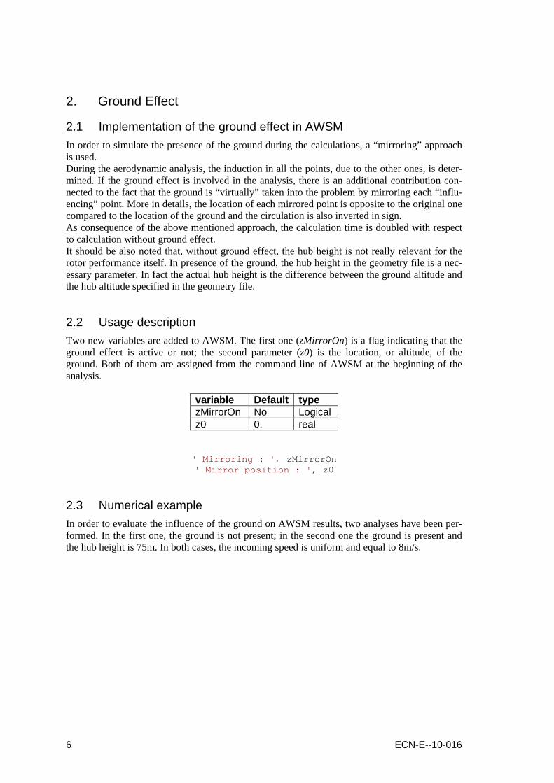
Figure 1 Side view of the wake. Comparison between ground (top) and no ground (bottom)
conditions.
Figure 2 Side view of the wake. Comparison between ground (top) and no ground (bottom)
conditions.
ECN-E--10-016 7
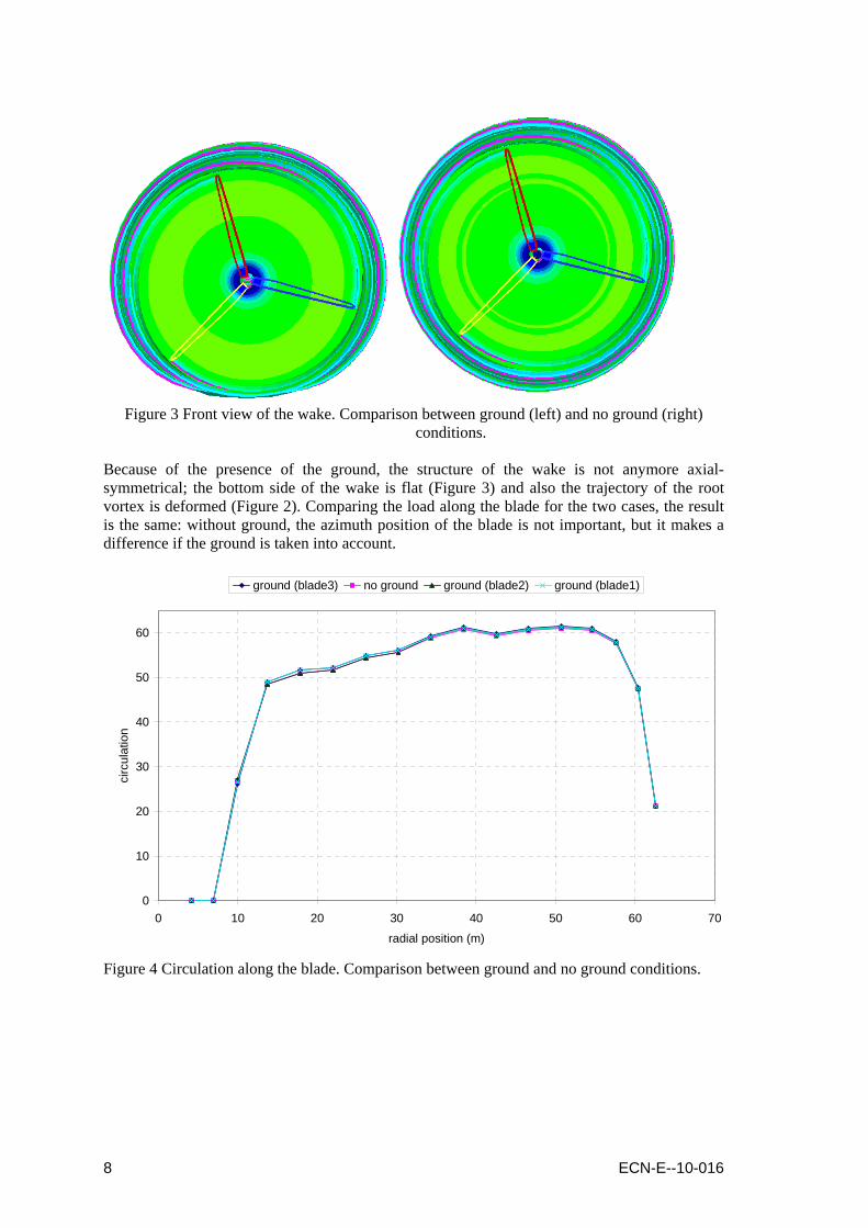
Figure 3 Front view of the wake. Comparison between ground (left) and no ground (right)
conditions. Because of the presence of the ground, the structure of the wake is not anymore axial-symmetrical; the bottom side of the wake is flat (Figure 3) and also the trajectory of the root vortex is deformed (Figure 2). Comparing the load along the blade for the two cases, the result is the same: without ground, the azimuth position of the blade is not important, but it makes a difference if the ground is taken into account.
0
10
20
30
40
50
60
0 10 20 30 40 50 60
radial position (m)
circ
ulat
ion
70
ground (blade3) no ground ground (blade2) ground (blade1)
Figure 4 Circulation along the blade. Comparison between ground and no ground conditions.
8 ECN-E--10-016
3. Wind Shear Effect
3.1 Implementation of the wind shear in AWSM AWSM has been extended to take into account the wind shear in the calculation. To do this, the equations that describe the three components of the wind speed have been modi-fied.
xzkuu x
α)10
(+= ∞ eq.1a
yzkvv yα)
10(+= ∞ eq.1b
zzkww z
α)10
(+= ∞ eq.1c
z is the altitude, κ and α, two parameters. α controls the shape of the shear and κ is an amplifier factor. The formulation is very similar to the one present in the IEC61400-1 International Stan-dard [5], so the analysis is conform to the certification rules. It is important to note that κ and α are independent parameters for each component. This means that it is possible also to assign a horizontal oriented wind profile. In AWSM, the wind conditions are assigned in “windscenario” file. In this file, it is possible to prescribe different wind speeds for different instants. Applied to the wind shear, this allows the user to simulate a time variant wind profile.
3.2 Usage description As mentioned in the previous paragraph, the data related to the wind are assigned in the “wind-scenario” file. In the previous version of AWSM, only the three components of a uniform wind were necessary and the tag <WindUVW> was used. <WindTimeInstance> <Time> 0.0 </Time> <WindUVW> 8.0 0.0 0.0 </WindUVW> </WindTimeInstance> After wind shear addition, other two tags are defined; <ShearExp>, in which α is defined and <ShearFactor> , in which κ is assigned. The default value for these variables is zero, so the user is not forced to use them if not necessary; this means also that the “windscenario” file created for the old version of AWSM doesn’t need modifications. <Time> 0.0 </Time> <WindUVW> 0.0 0.0 0.0 </WindUVW> <ShearExp> 0.55 0.0 0.0 </ShearExp> <ShearFactor> 2.38922256 0.0 0.0 </ShearFactor> </WindTimeInstance>
ECN-E--10-016 9

3.3 Numerical example In order to evaluate the influence of the wind shear on AWSM results, two analyses have been performed. In the first one, the wind shear is not present; in the second one the wind shear is present. In the first case, the incoming wind speed is uniform and equal to 8m/s; in the analysis with wind shear, the exponent α is 0.55 and the coefficient κ is 2.38922 in order to have 8m/s wind speed at hub height. In both cases the ground is not present.
Figure 5 Side view of the wake. Comparison between no wind shear (top) and wind shear
(bottom) conditions.
Figure 6 front view of the wake. Comparison between no wind shear (left) and wind shear
(right) conditions.
10 ECN-E--10-016
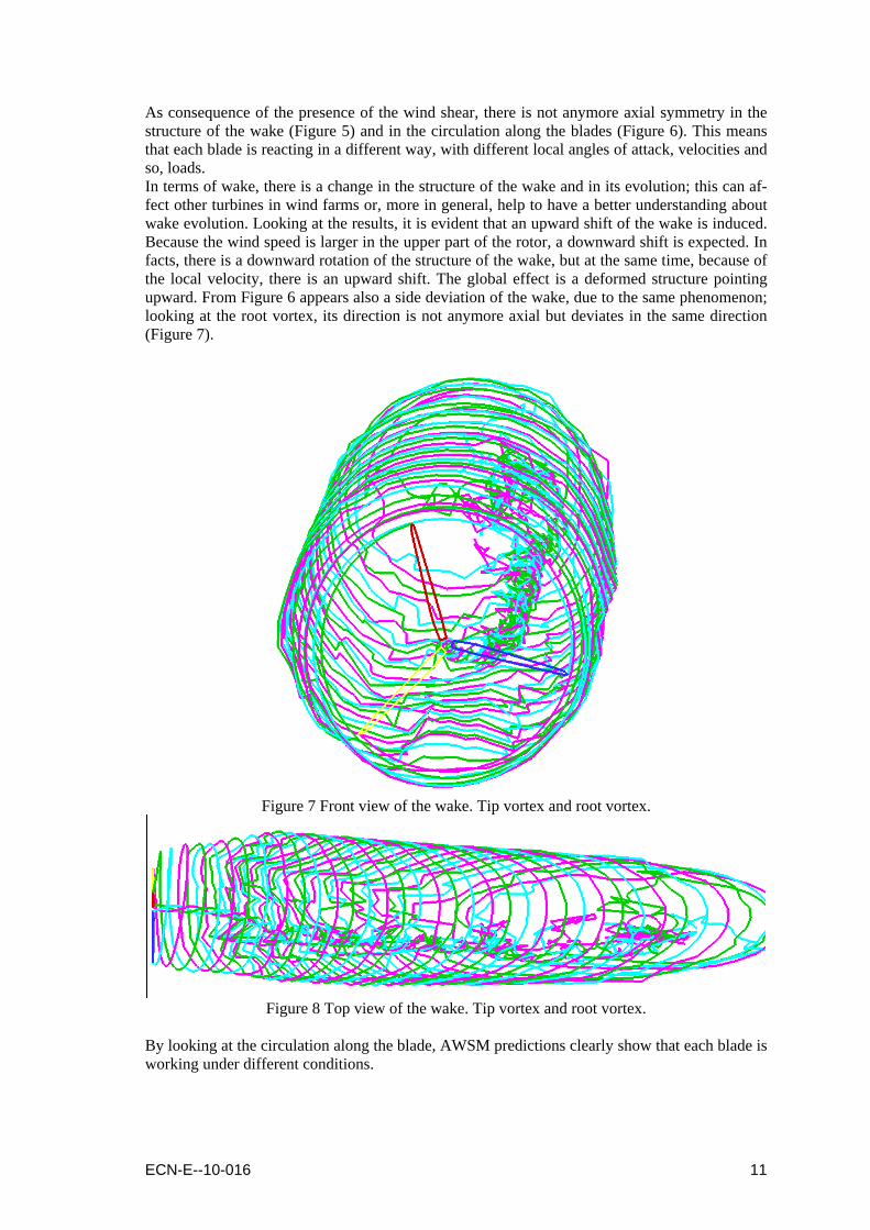
As consequence of the presence of the wind shear, there is not anymore axial symmetry in the structure of the wake (Figure 5) and in the circulation along the blades (Figure 6). This means that each blade is reacting in a different way, with different local angles of attack, velocities and so, loads. In terms of wake, there is a change in the structure of the wake and in its evolution; this can af-fect other turbines in wind farms or, more in general, help to have a better understanding about wake evolution. Looking at the results, it is evident that an upward shift of the wake is induced. Because the wind speed is larger in the upper part of the rotor, a downward shift is expected. In facts, there is a downward rotation of the structure of the wake, but at the same time, because of the local velocity, there is an upward shift. The global effect is a deformed structure pointing upward. From Figure 6 appears also a side deviation of the wake, due to the same phenomenon; looking at the root vortex, its direction is not anymore axial but deviates in the same direction (Figure 7).
Figure 7 Front view of the wake. Tip vortex and root vortex.
Figure 8 Top view of the wake. Tip vortex and root vortex.
By looking at the circulation along the blade, AWSM predictions clearly show that each blade is working under different conditions.
ECN-E--10-016 11

0
10
20
30
40
50
60
70
80
0 10 20 30 40 50 60
radial position (m)
circ
ulat
ion
70
no shear shear (blade1) shear (blade2) shear (blade3)
Figure 9 Circulation along the blade. Wind shear - no wind shear comparison.
12 ECN-E--10-016

ECN-E--10-016 13
4. Conclusions
The ground effect and wind shear effect have an important impact on wind turbine performance, aerodynamics and structural loads. Because of these two effects the response of the blades are different. Also in terms of wake, there is an influence due to these effects that changes the struc-ture of the wake and so, it has different impact on other turbines. In order to improve the accuracy of the numerical predictions, and having a more realistic model, both effects have been implemented in the ECN free vortex wake code AWSM. The us-ability of AWSM is also improved because effects due to real phenomena can be taken into ac-count and this allows the user to address important considerations connected with these aspects. For both extensions, the numerical examples show good results, consistent with physical expec-tations. More results, also in comparison with other models can be found in [6].
References
[1] A.Van Garrel, “Development of a Wind Turbine Aerodynamics Simulation Module”, ECN-C-03-079, August 2003.
[2] H.B. Hendriks, P.J. van Langen, and et al. Upwind reference wind turbine version 008.xls. Excel sheet (internal communication), February 16 2007.
[3] J. Jonkman, S. Butterfield, W. Musial, and G. Scott. Definition of a 5-mw reference wind turbine for offshore system development. Technical Report NREL/TP-500-38060, NREL, February 2009.
[4] www.upwind.eu [5] IEC61400-1 International Standard, Wind Turbine Generator Systems, Part1: Safety re-
quirements, IEC. [6] Madsen, A.H., Riziotis, V., Zahle, F., Larsen, T.J., Politis, E., Hanses, M.O.L., Snel, H.,
Grasso, F., “BEM modeling of inflow with shear in comparison with advanced model re-sults”, Torque 2010, EWEA, 28-30 june 2010, Crete, Greece. Also accepted for publication in Wiley&Sons, Wind Energy, special issue dedicated to UpWind project, 2011.


![[Louis Leithold] the Calculus, With Analytic Geome(BookFi.org)](https://static.fdocuments.net/doc/165x107/563dbcb5550346aa9ab0885d/louis-leithold-the-calculus-with-analytic-geomebookfiorg.jpg)