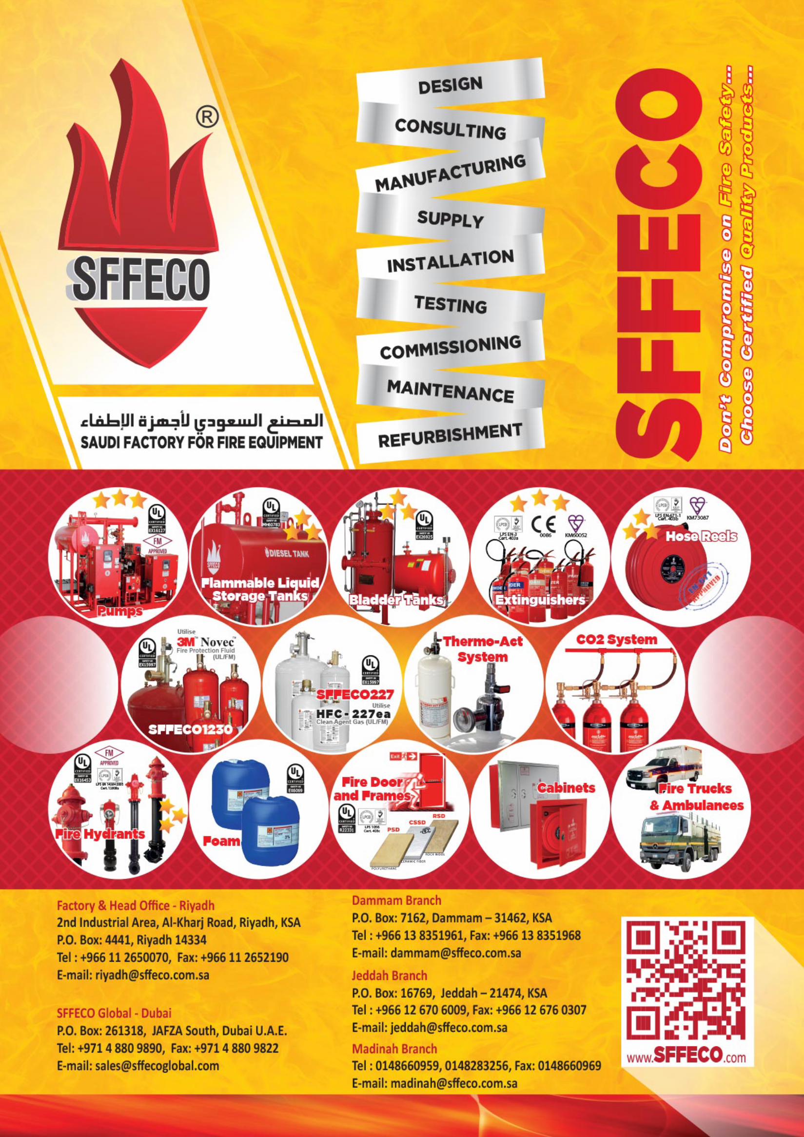
F Foam Systems - · PDF fileF Foam Systems F Deluge Systems F Hydrant Systems F Sprinkler...
24
F Foam Systems F Deluge Systems F Hydrant Systems F Sprinkler Systems F Hose Reel Systems F Hose Rack Systems
Transcript of F Foam Systems - · PDF fileF Foam Systems F Deluge Systems F Hydrant Systems F Sprinkler...
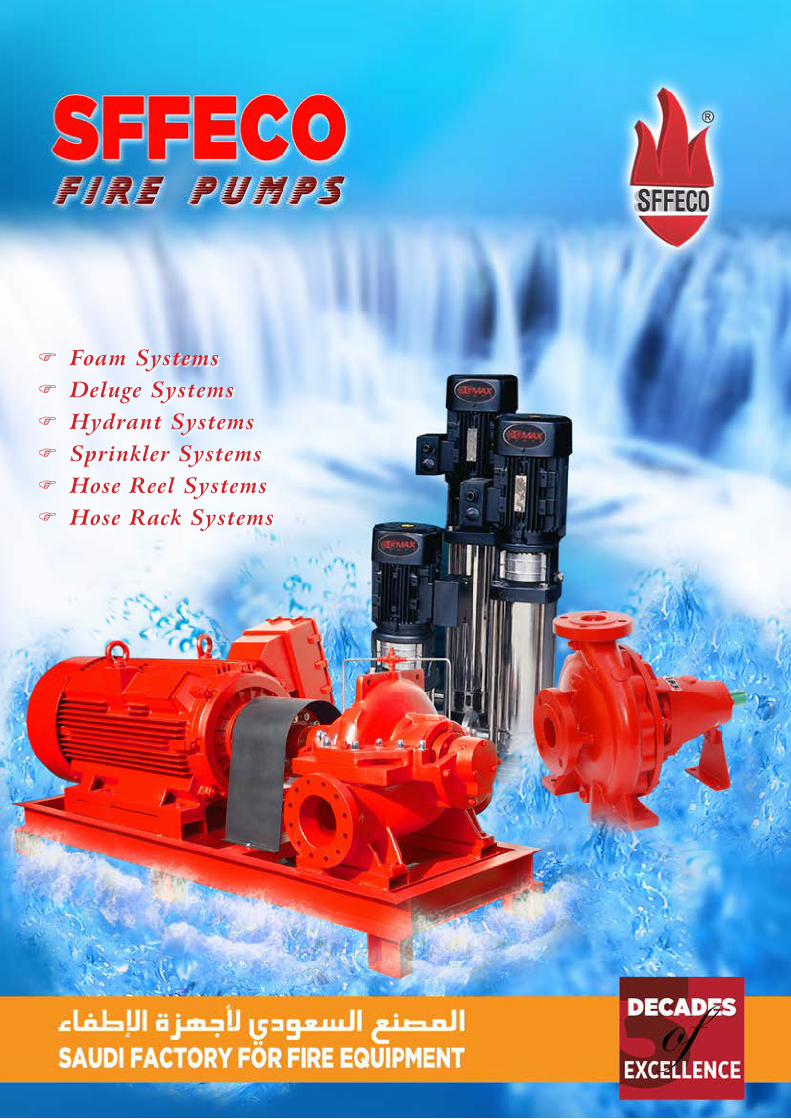
F Foam Systems F Deluge Systems F Hydrant Systems F Sprinkler Systems F Hose Reel Systems F Hose Rack Systems
www.SFFECO.com2
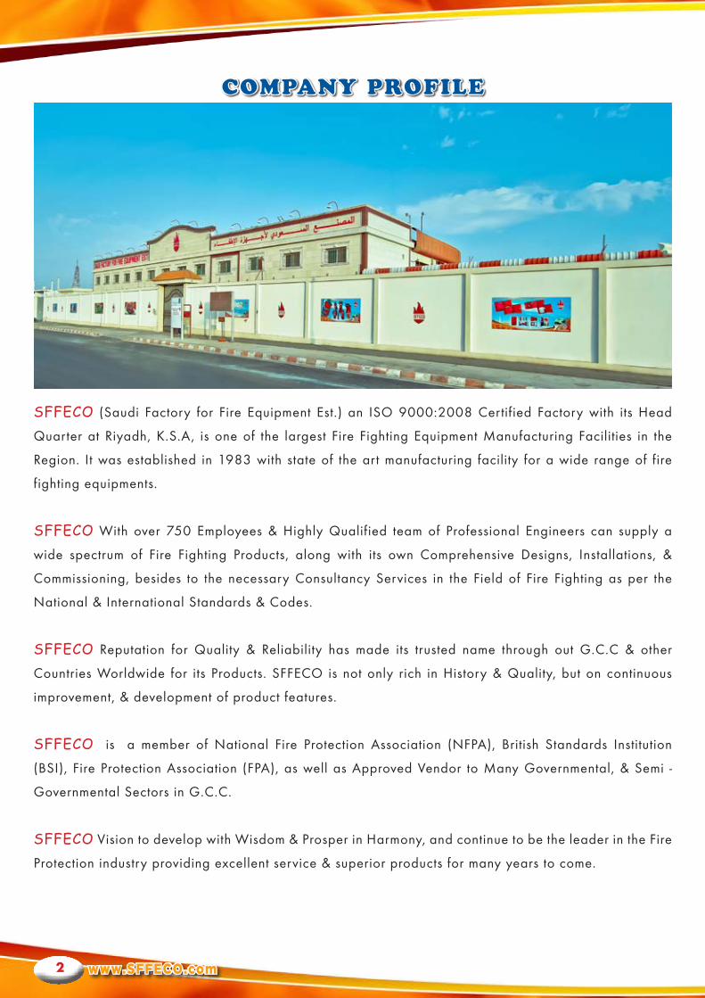
SFFECO (Saudi Factory for Fire Equipment Est.) an ISO 9000:2008 Certified Factory with its Head
Quarter at Riyadh, K.S.A, is one of the largest Fire Fighting Equipment Manufacturing Facilities in the
Region. It was established in 1983 with state of the art manufacturing facility for a wide range of fire
fighting equipments.
SFFECO With over 750 Employees & Highly Qualified team of Professional Engineers can supply a
wide spectrum of Fire Fighting Products, along with its own Comprehensive Designs, Installations, &
Commissioning, besides to the necessary Consultancy Services in the Field of Fire Fighting as per the
National & International Standards & Codes.
SFFECO Reputation for Quality & Reliability has made its trusted name through out G.C.C & other
Countries Worldwide for its Products. SFFECO is not only rich in History & Quality, but on continuous
improvement, & development of product features.
SFFECO is a member of National Fire Protection Association (NFPA), British Standards Institution
(BSI), Fire Protection Association (FPA), as well as Approved Vendor to Many Governmental, & Semi -
Governmental Sectors in G.C.C.
SFFECO Vision to develop with Wisdom & Prosper in Harmony, and continue to be the leader in the Fire
Protection industry providing excellent service & superior products for many years to come.
COMPANY PROFILE
S F F E C OFIRE PROTECTION ENGINEERS
3
Being Local Specialist Manufacture gives SFFECO the Opportunity and Privilege to Develop an Innovative
Pump Assembly Units, and Tailor Pump Packages to clients’ specific needs, Moreover SFFECO has assured
supplying Pump units comply with Local Authority Requirements, as well as NFPA - 20 Selection and
Operation Procedures.
SFFECO Highly Skilled Team has over 25 years Combined Experience in Design, Assembly, and Pump
Packages Testing…. Succeeded developing the “Excel SERIES” Pre- Fabricated Fire Pump Skids, where
this developed technology assure providing Compact Design Pump Sets, easily to Handle ,Install,&
Maintain ,where all Pumping Elements, Drivers, Controllers are all skid Mounted, Pre-piped, Wired, &
Factory tested .
Excel Series Standard Packages included wide variety of Fire Pump Units start from 50 GPM size
up to 1500 GPM, with pressure range from 6 bars up to 12 bars. This wide Range of Pumping &
Head Characteristics has Made Excel Series suitable in various market sectors such as; Government
Buildings, Commercial and Residential Towers, Ware houses, Factories etc.
Excel Series is the right Choice for most of the Fire Fighting Applications;
• FireHoseCabinetSystems.
•AutomaticSprinklerSystems.
•DelugeSystems.
•HydrantSystems.
• FoamSystems.
SFFECO Fire Pump System Technology
SYSTEM TECHNOLOGY
www.SFFECO.com4
“Excel Series” Packages Offers Completed Skid Mounted Unit including High quality Horizontal End
Suction / Split case Pumps that coupled with Heavy duty (Electrical/ Diesel) drivers that assembled with
full discharge line control Gate & Check Valves along with flexible joints. Pressure Switches & Gauge fitted
on well Supported Header, where all pre-piped, wired, & fabricated in Common Compact Skid is Fully
Automatic Operated through latest Design Control Panel.
“Excel Series” Innovated design has different Combinations & Models that suite different clients
requirements, as well as Hazard application needs.
The Standard Models of “Excel Series” are as Follows;
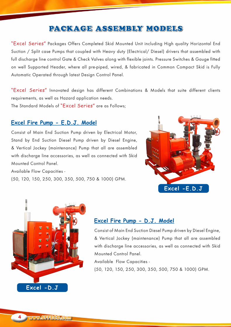
Consist of Main End Suction Pump driven by Electrical Motor,
Stand by End Suction Diesel Pump driven by Diesel Engine,
& Vertical Jockey (maintenance) Pump that all are assembled
with discharge line accessories, as well as connected with Skid
Mounted Control Panel.
Available Flow Capacities -
(50, 120, 150, 250, 300, 350, 500, 750 & 1000) GPM.
Consist of Main End Suction Diesel Pump driven by Diesel Engine,
& Vertical Jockey (maintenance) Pump that all are assembled
with discharge line accessories, as well as connected with Skid
Mounted Control Panel.
Available Flow Capacities -
(50, 120, 150, 250, 300, 350, 500, 750 & 1000) GPM.
PACKAGE ASSEMBLY MODELS
Excel Fire Pump - E.D.J. Model
Excel Fire Pump - D.J. Model
Excel -E.D.J
Excel -D.J
S F F E C OFIRE PROTECTION ENGINEERS
5
Consist of Main End Suction Pump driven by Electrical Motor,
& Vertical Jockey (maintenance) Pump that all are assembled
with discharge line accessories, as well as connected with Skid
Mounted Control Panel.
Available Flow Capacities -
(50, 120, 150,250, 300, 350, 500, 750 & 1000) GPM.
Consist of End Suction/Split Case Pump driven by Electrical Motor, (or /and) Split Case Diesel Pump
driven by Diesel Engine, (or /and) Vertical Jockey (maintenance) Pump, all are assembled on I-Beam base
separately ,where discharge line Accessories & Control Panel are supplied loosely .
Available in all Excel Series pumping flows (as per client request).
But this model is most in the following Conditions;
Note:
Optional Provision are also available in Excel Series can be Ordered up on Request such as;
- Different Combinations Double Electric (E.E.), or Double Diesel (D.D.) as Main & Stand by.
- Pressure Tank as additional on the skid or substitute to the Jockey Pump.
PACKAGE ASSEMBLY MODELS
Excel Fire Pump - E.J. Model
Horizontal Split Case Model
Excel -E.J
• Split Case Pump Bare Shaft.
• Flow Capacity above 750 GPM
(e.g. 1000, 1250, 1500) GPM.
• High Pumping Head above 9 Bar
www.SFFECO.com6
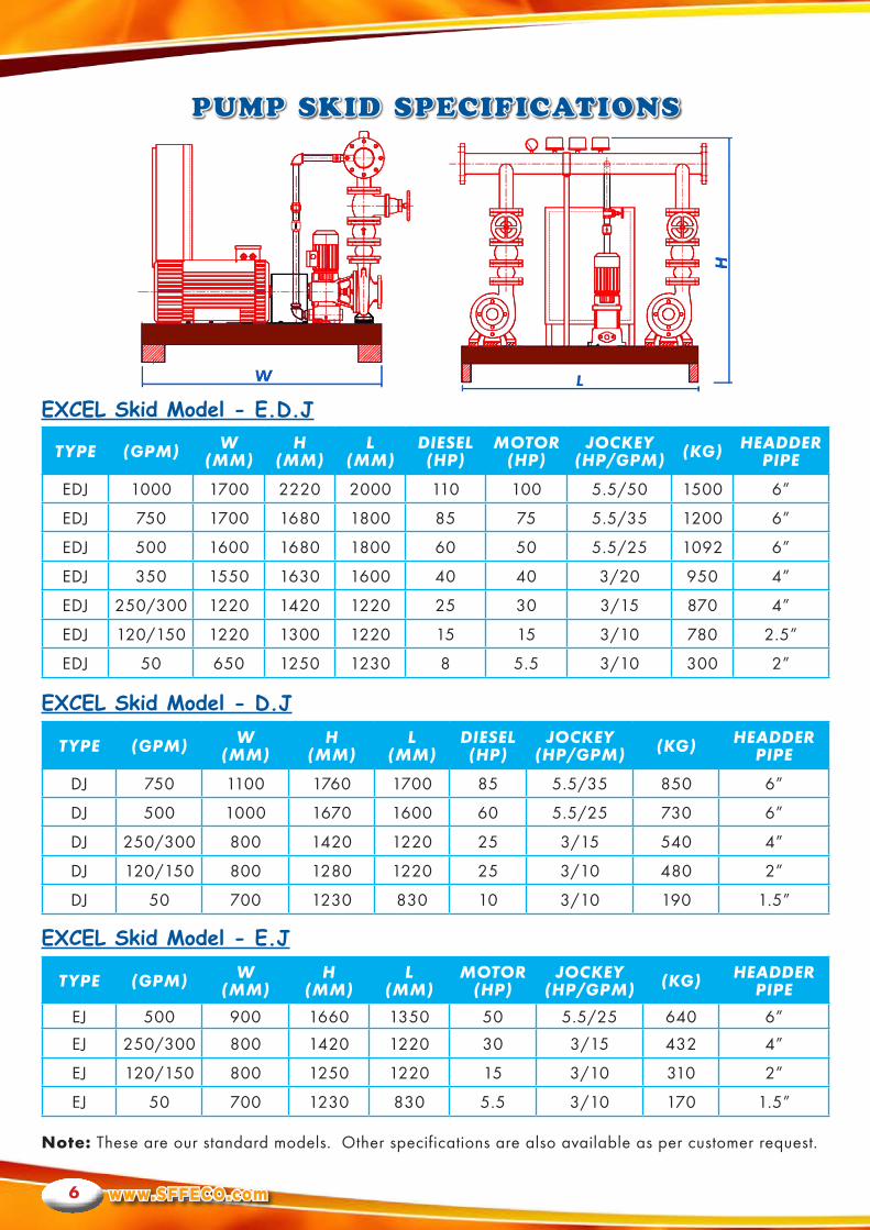
PUMP SKID SPECIFICATIONS
EXCEL Skid Model - E.D.J
EXCEL Skid Model - D.J
EXCEL Skid Model - E.J
TYPE (GPM) W(MM)
H(MM)
L(MM)
DIESEL(HP)
MOTOR(HP)
JOCKEY(HP/GPM) (KG) HEADDER
PIPE
EDJ 1000 1700 2220 2000 110 100 5.5/50 1500 6”
EDJ 750 1700 1680 1800 85 75 5.5/35 1200 6”
EDJ 500 1600 1680 1800 60 50 5.5/25 1092 6”
EDJ 350 1550 1630 1600 40 40 3/20 950 4”
EDJ 250/300 1220 1420 1220 25 30 3/15 870 4”
EDJ 120/150 1220 1300 1220 15 15 3/10 780 2.5”
EDJ 50 650 1250 1230 8 5.5 3/10 300 2”
TYPE (GPM) W(MM)
H(MM)
L(MM)
DIESEL(HP)
JOCKEY(HP/GPM) (KG) HEADDER
PIPE
DJ 750 1100 1760 1700 85 5.5/35 850 6”
DJ 500 1000 1670 1600 60 5.5/25 730 6”
DJ 250/300 800 1420 1220 25 3/15 540 4”
DJ 120/150 800 1280 1220 25 3/10 480 2”
DJ 50 700 1230 830 10 3/10 190 1.5”
TYPE (GPM) W(MM)
H(MM)
L(MM)
MOTOR(HP)
JOCKEY(HP/GPM) (KG) HEADDER
PIPE
EJ 500 900 1660 1350 50 5.5/25 640 6”
EJ 250/300 800 1420 1220 30 3/15 432 4”
EJ 120/150 800 1250 1220 15 3/10 310 2”
EJ 50 700 1230 830 5.5 3/10 170 1.5”
Note:These are our standard models. Other specifications are also available as per customer request.
S F F E C OFIRE PROTECTION ENGINEERS
7
SKID PACKAGE COMPONENTS
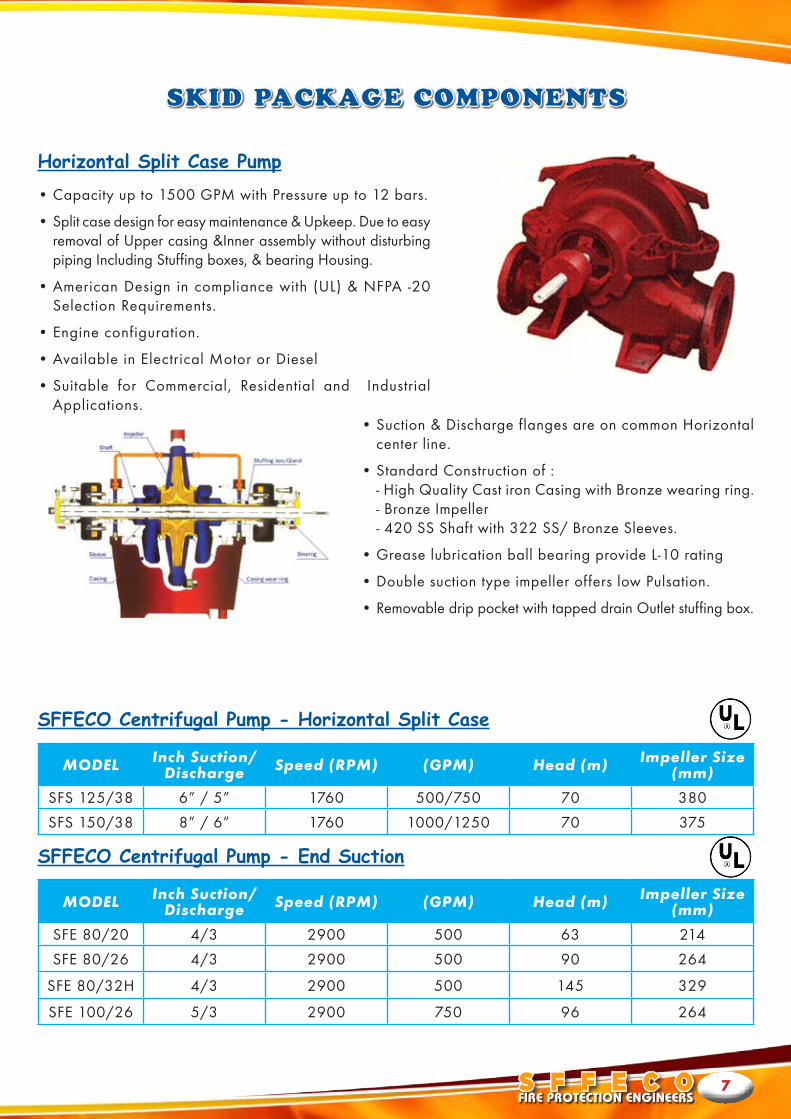
Horizontal Split Case Pump
SFFECO Centrifugal Pump - Horizontal Split Case
SFFECO Centrifugal Pump - End Suction
•Capacity up to 1500 GPM with Pressure up to 12 bars.
•Split case design for easy maintenance & Upkeep. Due to easy removal of Upper casing &Inner assembly without disturbing piping Including Stuffing boxes, & bearing Housing.
•American Design in compliance with (UL) & NFPA -20 Selection Requirements.
•Engine configuration.
•Available in Electrical Motor or Diesel
•Suitable for Commercial, Residential and Industrial Applications.
•Suction & Discharge flanges are on common Horizontal center line.
•Standard Construction of :- High Quality Cast iron Casing with Bronze wearing ring.- Bronze Impeller- 420 SS Shaft with 322 SS/ Bronze Sleeves.
•Grease lubrication ball bearing provide L-10 rating
•Double suction type impeller offers low Pulsation.
•Removable drip pocket with tapped drain Outlet stuffing box.
MODEL Inch Suction/ Discharge Speed (RPM) (GPM) Head (m) Impeller Size
(mm)
SFS 125/38 6” / 5” 1760 500/750 70 380
SFS 150/38 8” / 6” 1760 1000/1250 70 375
MODEL Inch Suction/ Discharge Speed (RPM) (GPM) Head (m) Impeller Size
(mm)
SFE 80/20 4/3 2900 500 63 214
SFE 80/26 4/3 2900 500 90 264
SFE 80/32H 4/3 2900 500 145 329
SFE 100/26 5/3 2900 750 96 264
www.SFFECO.com8
SKID PACKAGE COMPONENTS
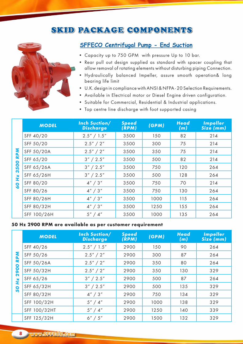
• Capacity up to 750 GPM with pressure Up to 10 bar.
• Rear pull out design supplied as standard with spacer coupling that allow removal of rotating elements without disturbing piping Connection.
• Hydraulically balanced Impeller, assure smooth operation& long bearing life limit
• U.K. design in compliance with ANSI & NFPA - 20 Selection Requirements.
• Available in Electrical motor or Diesel Engine driven configuration.
• Suitable for Commercial, Residential & Industrial applications.
• Top centre line discharge with foot supported casing
50Hz2900RPMareavailableaspercustomerrequirement
SFFECO Centrifugal Pump - End Suction
50
Hz
29
00
RP
M
MODEL Inch Suction/Discharge
Speed(RPM) (GPM) Head
(m)Impeller
Size (mm)
SFF 40/26 2.5” / 1.5” 2900 150 90 264
SFF 50/26 2.5” / 2” 2900 300 87 264
SFF 50/26A 2.5” / 2” 2900 350 80 264
SFF 50/32H 2.5” / 2” 2900 350 130 329
SFF 65/26 3” / 2.5” 2900 500 87 264
SFF 65/32H 3” / 2.5” 2900 500 135 329
SFF 80/32H 4” / 3” 2900 750 134 329
SFF 100/32H 5” / 4” 2900 1000 138 329
SFF 100/32HT 5” / 4” 2900 1250 140 339
SFF 125/32H 6” / 5” 2900 1500 132 329
60
Hz
35
00
RP
M
MODEL Inch Suction/Discharge
Speed(RPM) (GPM) Head
(m)Impeller
Size (mm)
SFF 40/20 2.5” / 1.5” 3500 150 82 214
SFF 50/20 2.5” / 2” 3500 300 75 214
SFF 50/20A 2.5” / 2” 3500 350 75 214
SFF 65/20 3” / 2.5” 3500 500 82 214
SFF 65/26A 3” / 2.5” 3500 750 120 264
SFF 65/26H 3” / 2.5” 3500 500 128 264
SFF 80/20 4” / 3” 3500 750 70 214
SFF 80/26 4” / 3” 3500 750 130 264
SFF 80/26H 4” / 3” 3500 1000 115 264
SFF 80/32H 4” / 3” 3500 1250 155 264
SFF 100/26H 5” / 4” 3500 1000 135 264

S F F E C OFIRE PROTECTION ENGINEERS
9
SKID PACKAGE COMPONENTS
Vertical In-line Pump
Electric Motor
Vertical In-line pump is designed such that motor may be removed without complete dissemble of the pump. The back pull out design is convenient when there is a need for inspection, repair or for changing the impeller without disturbing the piping system. the vertical in-line has a centre line suction and discharge with a space saving design. The enclosed impeller may be dynamically balanced and the renewable wearing maintains peak efficiency. Each impeller has back pull out vanes to provide a clear passage way against material build up behind the impeller. The impeller is designed to reduce end thrust. Larger pumps have an additional wearing in the rear to provide additional wear resistance.
HITEC motor plays a vital role in “Excel Series” Fire Pump Packages as it is Electrical Motor fire pump driver on both Main (or/and) Standby Operation, that arranged to allow power take-off through a flexible coupling directly from motor shaft “rotating element”, where this power is designed to allow the working space required for serving a fire pump when a pump is directly connected to a Motor.
HITEC Induction motors are U.K. designed motors, which have been designed according to the EIC standards, with special features & characteristics have made HITEC Motors Durable Motors & Components,
Centrifugal Vertical In-line
Item No.
Rated Head (PSI)
Rated Head (Bar)
Rated Speed (GPM)
Rated Capacity
(GPM)
Refer Bulletin
Suc/Dis.Dia
Maximum Working Pressure
Type
1 62~88 4.27~6.07 2900 200 KTG65/20II 2.5” 230 psi 2½x2½-8
2 45~54 3.1~3.72 1450 400 KTG125/32 5” 230 psi 5x5-13
3 51~83 3.52~5.7 1450 750 KTG150/40 6” 230 psi 6x6-16
4 48~80 3.31~5.52 1760 500 KTG125/32 5” 230 psi 5x5-13
5 80~120 5.52~8.27 1760 1000 KTG150/40 6” 230 psi 6x6-16
Low Vibration design “Silent Functioning”, Corrosion proof construction, & trouble free performance that easily to maintain. HITEC motors can handle load, & continue working reliably for long hours, also the precision balanced design ensures super performance with minimum energy consumption.
HITEC standard construction of the Motor Frame, & Shield Ends (Drive/Non-Drive) from Cast Iron, Cathode Copper Stator, & Aluminum Rotor, where both are insulated by low-carbon magnetic steel laminations. The Motor Shaft made of superior grade Steel, along with Ball Bearing fully sealed, & pre-packed with grease .Motor has IP55 Protection, and Fan Cooling with Steel Cover protection of IP 2 x, Moreover Class F insulation allows temperature rises up to 100K, & max. Temp. Of 155 °C at the machine spots.
www.SFFECO.com10
Model At 60 HzKW HP
Speed (R.P.M)
CurrentA
Efficiency%
FactorCos
TorqueNm
NoiseLwdB(A)
WeightKg.
MAINSSU
PPLY220-240,380-460V.60Hz,3PHASE,2POLE
HM 801 – 2 0.75 1 3400 1.8 75.0 0.83 2.54 67 16.5
HM 802 – 2 1.1 1.5 3400 2.6 77.0 0.84 3.72 67 17.5
HM 90S - 2 1.5 2 3420 3.4 79.0 0.84 5.04 72 21
HM 90L – 2 2.2 3 3450 4.9 81.0 0.85 7.40 72 25
HM 100L - 2 3 4 3450 6.3 83.0 0.87 9.95 76 33
HM 112M - 2 4 5.5 3455 8.1 85.0 0.88 13.22 77 41
HM 132S1 - 2 5.5 7.5 3490 11.0 86.0 0.88 18.11 80 63
HM 132S2 - 2 7.5 10 3550 14.9 87.0 0.87 24.70 80 70
HM 160M1 - 2 11 15 3485 21.3 88.0 0.89 35.85 86 110
HM 160M2 - 2 15 20 3550 28.8 89.0 0.89 48.89 86 120
HM 160L – 2 18.5 25 3490 34.7 90.0 0.90 60.30 86 135
HM 180M - 2 22 30 3545 41.0 90.5 0.90 71.46 89 165
HM 200L1 - 2 30 40 3545 55.5 91.2 0.90 97.12 92 218
HM 200L2 - 2 37 50 3550 67.9 92.0 0.90 119.78 92 230
HM 225M - 2 45 60 3560 82.3 92.3 0.90 144.70 92 280
HM 250M - 2 55 75 3555 100.4 92.5 0.90 176.85 93 365
HM 280S - 2 75 100 3560 134.4 93.2 0.91 241.16 94 495
HM 280M - 2 90 125 3575 160.2 93.8 0.91 289.39 94 565
HM 315S -2 110 150 3575 195.4 94.0 0.91 352.51 96 890
HM 315M - 2 132 180 3575 233.2 94.5 0.91 423.02 96 980
HM 315L1 - 2 160 220 3575 279.3 94.6 0.92 512.75 99 1055
HM 315L2 - 2 200 270 3575 348.4 94.8 0.92 640.94 99 1110
MAINSSU
PPLY220-380,380-660V.60Hz,3PHASE,2POLE HM 802 - 4 0.75 1 1730 2.0 73.0 0.77 5.15 58 16
HM 90S - 4 1.1 1.5 1710 2.9 75.0 0.77 7.50 61 23
HM 90L - 4 1.5 2 1715 3.7 78.0 0.79 10.23 61 25
HM 100L1 - 4 2.2 3 1710 5.2 80.0 0.81 14.80 64 33
HM 100L2 - 4 3 4 1730 6.8 82.0 0.82 20.18 64 35
HM 112M - 4 4 5.5 1730 8.8 84.0 0.82 26.53 65 41
HM 132S - 4 5.5 7.5 1730 11.8 85.0 0.83 36.48 71 65
HM 132M - 4 7.5 10 1760 15.6 87.0 0.84 49.74 71 76
HM 160M - 4 11 15 1755 22.3 88.0 0.85 71.59 75 118
HM 160L - 4 15 20 1760 30.1 89.0 0.85 98.12 75 132
HM 180M - 4 18.5 25 1760 36.5 90.5 0.85 120.19 76 164
HM 180L - 4 22 30 1765 43.2 91.0 0.85 142.93 76 182
HM 200L - 4 30 40 1770 57.6 92.0 0.86 160.96 79 245
HM 225S - 4 37 50 1775 69.9 92.5 0.87 198.51 81 258
HM 225M - 4 45 60 1775 84.7 92.8 0.87 290.37 81 290
HM 250M - 4 55 75 1775 103.3 93.0 0.87 354090 83 388
HM 250S - 4 75 100 1780 139.6 93.8 0.87 483.95 88 510
HM 280S - 4 90 125 1780 166.9 94.2 0.87 578.79 86 606
HM 315S - 4 110 150 1785 201.0 94.5 0.88 707.41 93 910
HM 315M - 4 132 175 1780 240.4 94.8 0.88 848.89 93 1000
HM 315L1 - 4 160 220 1780 287.8 94.9 0.89 1028.96 97 1055
HM 315L2 - 4 200 270 1785 359.4 95.0 0.89 1286.20 97 1128
S F F E C OFIRE PROTECTION ENGINEERS
11
SKID PACKAGE COMPONENTS
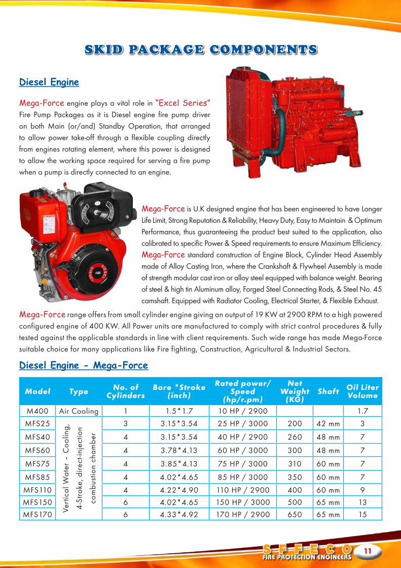
Mega-Force engine plays a vital role in “Excel Series” Fire Pump Packages as it is Diesel engine fire pump driver on both Main (or/and) Standby Operation, that arranged to allow power take-off through a flexible coupling directly from engines rotating element, where this power is designed to allow the working space required for serving a fire pump when a pump is directly connected to an engine.
Mega-Force is U.K designed engine that has been engineered to have Longer Life Limit, Strong Reputation & Reliability, Heavy Duty, Easy to Maintain & Optimum Performance, thus guaranteeing the product best suited to the application, also calibrated to specific Power & Speed requirements to ensure Maximum Efficiency.Mega-Force standard construction of Engine Block, Cylinder Head Assembly made of Alloy Casting Iron, where the Crankshaft & Flywheel Assembly is made of strength modular cast iron or alloy steel equipped with balance weight. Bearing of steel & high tin Aluminum alloy, Forged Steel Connecting Rods, & Steel No. 45 camshaft. Equipped with Radiator Cooling, Electrical Starter, & Flexible Exhaust.
Mega-Force range offers from small cylinder engine giving an output of 19 KW at 2900 RPM to a high powered configured engine of 400 KW. All Power units are manufactured to comply with strict control procedures & fully tested against the applicable standards in line with client requirements. Such wide range has made Mega-Force suitable choice for many applications like Fire fighting, Construction, Agricultural & Industrial Sectors.
Diesel Engine - Mega-Force
Diesel Engine
Model Type No. of Cylinders
Bore *Stroke(inch)
Rated power/Speed
(hp/r.pm)
NetWeight
(KG)Shaft Oil Liter
Volume
M400 Air Cooling 1 1.5*1.7 10 HP / 2900 1.7
MFS25
Vert
ical
Wat
er –
Coo
ling,
4-S
trok
e, d
irect
-inje
ctio
n
com
bust
ion
cham
ber
3 3.15*3.54 25 HP / 3000 200 42 mm 3
MFS40 4 3.15*3.54 40 HP / 2900 260 48 mm 7
MFS60 4 3.78*4.13 60 HP / 3000 300 48 mm 7
MFS75 4 3.85*4.13 75 HP / 3000 310 60 mm 7
MFS85 4 4.02*4.65 85 HP / 3000 350 60 mm 7
MFS110 4 4.22*4.90 110 HP / 2900 400 60 mm 9
MFS150 6 4.02*4.65 150 HP / 3000 500 65 mm 13
MFS170 6 4.33*4.92 170 HP / 2900 650 65 mm 15
www.SFFECO.com12
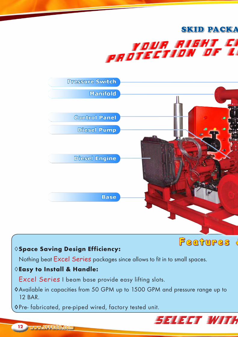
SKID PACKAGE DETAILS
F e a t u r e s & B e n e f i t s◊SpaceSavingDesignEfficiency:
Nothing beat Excel Series packages since allows to fit in to small spaces.
◊EasytoInstall&Handle:
Excel Series I beam base provide easy lif ting slots.
◊Available in capacities from 50 GPM up to 1500 GPM and pressure range up to 12 BAR.
◊Pre- fabricated, pre-piped wired, factory tested unit.
SELECT WITH CONFIDENCE
S F F E C OFIRE PROTECTION ENGINEERS
13
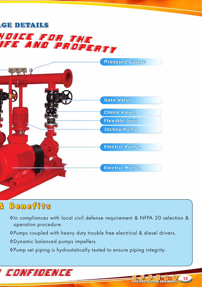
SKID PACKAGE DETAILS
F e a t u r e s & B e n e f i t s◊In compliances with local civil defense requirement & NFPA 20 selection &
operation procedure.
◊Pumps coupled with heavy duty trouble free electrical & diesel drivers.
◊Dynamic balanced pumps impellers.
◊Pump set piping is hydrostatically tested to ensure piping integrity.
SELECT WITH CONFIDENCE
www.SFFECO.com14
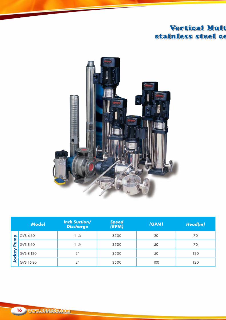
Vertical Multistage in-line stainless steel centrifugal pumps
Application:
Usage:
Example:
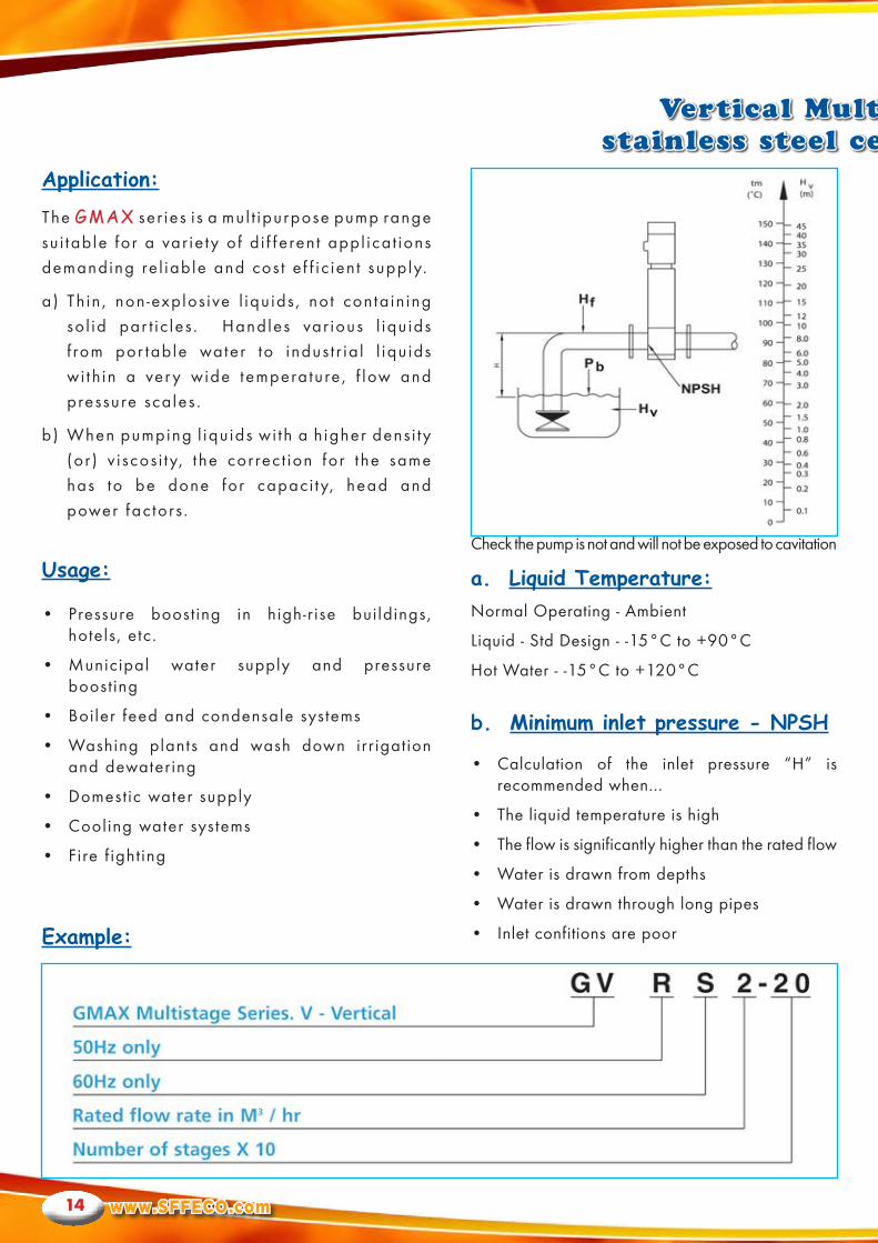
a. Liquid Temperature:
b. Minimum inlet pressure - NPSH
The GMAX ser ies i s a mul t ipurpose pump range su i tab le for a var ie ty o f d i f fe ren t appl ica t ions demanding re l iab le and cos t e f f ic ien t supply.
a) Th in , non -explos ive l iqu ids , no t conta in ing so l id par t ic les . Handles var ious l iqu ids f rom por table water to indus t r ia l l iqu ids wi th in a ver y wide temperature , f low and pressure sca les .
b) When pumping l iqu ids wi th a h igher dens i ty (or ) v i scos i ty, t he cor rec t ion for t he same has to be done for capaci ty, head and power fac tors .
Normal Operating - Ambient
Liquid - Std Design - -15°C to +90°C
Hot Water - -15°C to +120°C
• Calculation of the inlet pressure “H” is recommended when...
• The liquid temperature is high
• The flow is significantly higher than the rated flow
• Water is drawn from depths
• Water is drawn through long pipes
• Inlet confitions are poor
• Pressure boost ing in high-r ise buildings, hotels, etc.
• Municipal water supply and pressure boost ing
• Boiler feed and condensale systems
• Washing plants and wash down irr igation and dewater ing
• Domestic water supply
• Cooling water systems
• Fire f ight ing
Check the pump is not and will not be exposed to cavitation
S F F E C OFIRE PROTECTION ENGINEERS
15
Vertical Multistage in-line stainless steel centrifugal pumps
Electrical DataProtection Class: IP55
Insulation Class : F
Standard Voltage: 50Hz.: 3 x 200-220 / 346-380V 3 x 220-240 / 380-415V 3 x 380-415V
Standard Voltage: 60Hz.: 3 x 200-230 / 346-400V 3 x 200-255 / 380-440V 3 x 200-277V/380-480V
To avoid cav i ta t ion , make sure tha t t here i s a
min imum pressure on the suc t ion s ide of t he
pump. The maximum suc t ion l i f t “H” in meters
head can be calcu la ted as fo l lows
H = Pb x 10.2 - NPSH - Hf - Hv - Hs
Pb = Baromet r ic Pressure in bar.
(Baromet r ic pressure can be se t to 1 bar. )
In c losed sys tems, Pb ind icates t he sys tem
pressure in bar.
NPSH = Net Pos i t i ve Suc t ion Head in meters
head.
(To be read f rom the NPSH cur ve a t t he h ighes t
f low the pump wi l l be de l iver ing. )
Hf = Fr ic t ion loss in suc t ion p ipe in meters
head.
(A t t he h ighes t f low the pump wi l l be
de l iver ing. )
Hv = Vapor pressure in meters head.
(To be read f rom the vapor pressure sca le .
“Hv” depends on the l iqu id temperature”Tm”)
Hs = Safe ty margin = min imum 0.5 meters
head.
(To be read f rom the vapor pressure sca le .
“Hv” depends on the l iqu id temperature “Tm”)
I f t he “H” calcu la ted i s pos i t i ve , t he pump
can operate a t a suc t ion l i f t o f maximum “H”
meters head.
I f t he “H” calcu la ted i s negat ive , an in le t
pressure o f min imum “H” meters head i s
requi red.
c. Motor
The motor is Totally Enclosed, Fan-Cooled, 2-pole
with principal dimensions in accordance with EN
standards
Electrical tolerances according to EN60034
Motor Protection
• Single phase motors have a built in thermal
overload switch
• Three phase motors must be connected to a motor
startyer in accordance with local regulations
• Three phase motors from 3kW and upwards have a
built-in thermostat (PTC) according to DIN 44 082.
Ambient Temperature
Maximum +40°C
If the ambient temperature exceeds +40°C or if the
motor is located 1000 meters above sea level, the
motor output (P2) must be reduced due to the low
density and consequently low cooling effect of the
air. In such cases, it may be necessary to use a
motor with a higher output.
www.SFFECO.com16
Vertical Multistage in-line stainless steel centrifugal pumps
Model Inch Suction/Discharge
Speed(RPM) (GPM) Head(m)
JockeyPump GVS 4-60 1 ¼ 3500 20 70
GVS 8-60 1 ½ 3500 50 70
GVS 8-120 2” 3500 50 120
GVS 16-80 2” 3500 100 120
S F F E C OFIRE PROTECTION ENGINEERS
17
Vertical Multistage in-line stainless steel centrifugal pumps
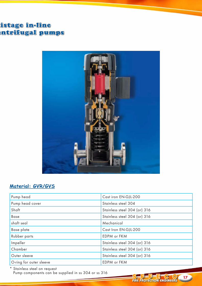
Material: GVR/GVS
Pump head Cast iron EN-GJL-200
Pump head cover Stainless steel 304
Shaft Stainless steel 304 (or) 316
Base Stainless steel 304 (or) 316
shaft seal Mechanical
Base plate Cast Iron EN-GJL-200
Rubber parts EDPM or FKM
Impeller Stainless steel 304 (or) 316
Chamber Stainless steel 304 (or) 316
Outer sleeve Stainless steel 304 (or) 316
O-ring for outer sleeve EDPM or FKM
* Stainless steel on request Pump components can be supplied in ss 304 or ss 316
www.SFFECO.com18
FIRE PUMP CONTROLLERS
Pump Controller Features
“Excel Series” F i re Pump Uni t Cont ro l le r i s t he Pump Package bra in tha t des igned to Cont ro l
& Moni tor t he operat ion of t he Main , S tandby, and Jockey pumps Dr ivers , and makes up
pumps for both Manual & Automat ic modes , as wel l as tu rns pumps dr ivers ON/OFF under
spec i f ic condi t ions .
The F i re Pump Package Cont ro l le r de tec ts s ignals t h rough se t o f bu i l t in swi tches tha t re f lec t t he
sys tem Pressure & F low s ta tus enabl ing f i re pump package dr ivers (E lec t r ica l /Diese l /Jockey)
to operate in case of pressure in t he sys tem i s lower than se t poin t , as wel l as operat ing the
S tand by dr iver due to power fa i lu re and/or subs tan t ia l drop in pressure .
SFFECO’s Excel Series Cont ro l le rs are pre -wi red, and fac tor y tes ted before sh ipment and
made ready for immedia te usage.
• Standard Dr y Run Pro tec t ion (above 100
GPM pumps) .
•DOL – (Be low 60 HP Motor S ize) / S tar
Del ta S tar ter Ci rcu i t avai lable up on reques t .
•Di f feren t Mount ing S ty les .
•NFPA Ar rangement / IP s tandard Avai lable
up on reques t (Opt ional ) .
• Low Main tenance Cos t and avai lable spare
par t s .
• Standard cable mark ing for easy
main tenance.
• Low Pressure cu t -o f f ( t imer based) (opt ional ) .
•Automat ic or manual ( tes t ) operat ion .
•Compat ib le wi th any remote s ignal ing or
moni tor ing sys tems l ike BMS OR FACP.
• Elec t ron ic bat ter y charger (cur ren t sens ing) .
• Lamp tes t fac i l i ty (op t ional ) .
• Faul t Tr ip fac i l i ty (o ther t han dr y run -
op t ional ) .
•Crank pro tec t ion c i rcu i t for d iese l engine
(opt ional ) .
•Delayed s tar t for f i re s ignal (op t ional ) .
• St rong, Re l iable and E legant S tandard Red
Powder Coated Galvanized S tee l Enc losure .
• Sta in less S tee l Enc losures are avai lable for
ou t door appl ica t ions (Opt ional ) .
S F F E C OFIRE PROTECTION ENGINEERS
19
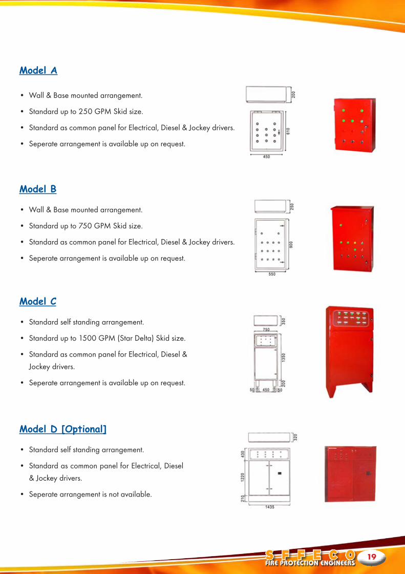
Model A
Model B
Model C
Model D [Optional]
• Wall & Base mounted arrangement.
• Standard up to 250 GPM Skid size.
• Standard as common panel for Electrical, Diesel & Jockey drivers.
• Seperate arrangement is available up on request.
• Wall & Base mounted arrangement.
• Standard up to 750 GPM Skid size.
• Standard as common panel for Electrical, Diesel & Jockey drivers.
• Seperate arrangement is available up on request.
• Standard self standing arrangement.
• Standard up to 1500 GPM (Star Delta) Skid size.
• Standard as common panel for Electrical, Diesel &
Jockey drivers.
• Seperate arrangement is available up on request.
• Standard self standing arrangement.
• Standard as common panel for Electrical, Diesel
& Jockey drivers.
• Seperate arrangement is not available.
www.SFFECO.com20
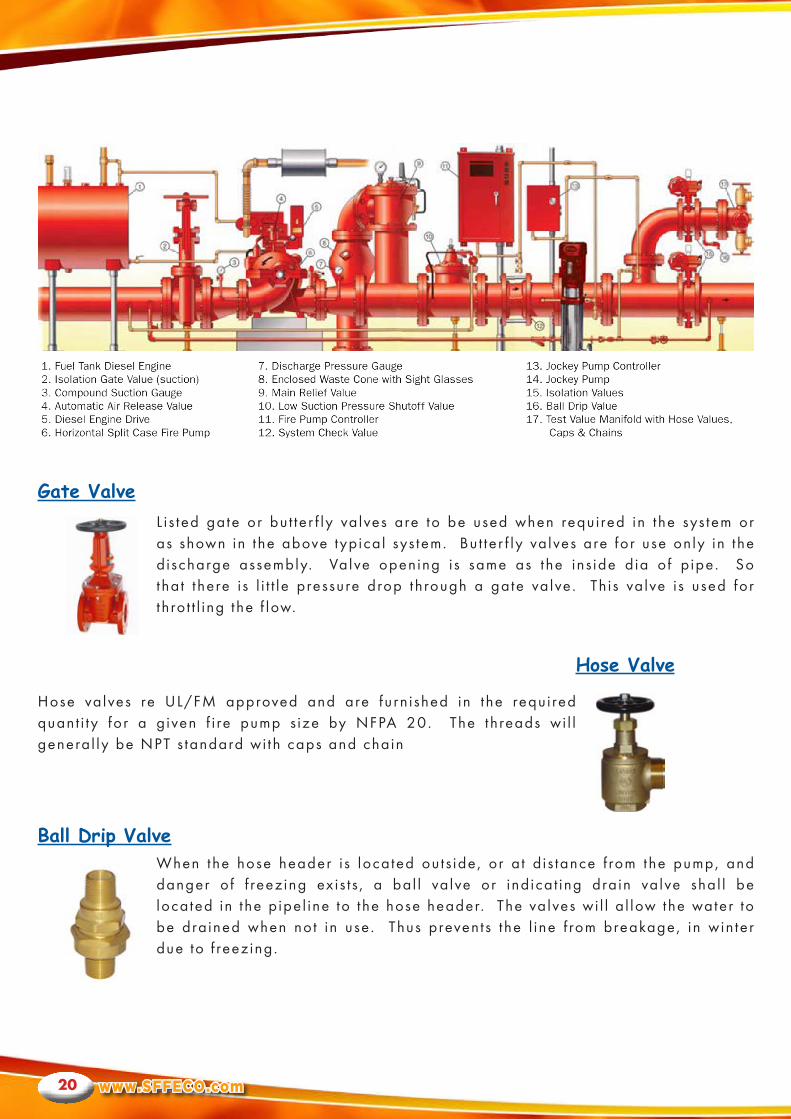
L i s ted gate or bu t ter f ly va lves are to be used when requi red in t he sys tem or as shown in the above typ ica l sys tem. Bu t ter f ly va lves are for use on ly in t he d ischarge assembly. Valve opening i s same as the ins ide d ia of p ipe. So tha t t here i s l i t t le pressure drop through a gate va lve . Th i s va lve i s used for t h ro t t l ing the f low.
Hose va lves re UL/FM approved and are furn i shed in t he requi red quant i ty for a g iven f i re pump s ize by NFPA 20. The threads wi l l genera l ly be NPT s tandard wi th caps and chain
When the hose header i s located ou ts ide, or a t d i s tance f rom the pump, and danger o f f reez ing ex is t s , a bal l va lve or ind ica t ing dra in va lve shal l be located in t he p ipe l ine to the hose header. The va lves wi l l a l low the water to be dra ined when not in use . Thus prevents t he l ine f rom breakage, in win ter due to f reez ing.
Gate Valve
Hose Valve
Ball Drip Valve
S F F E C OFIRE PROTECTION ENGINEERS
21
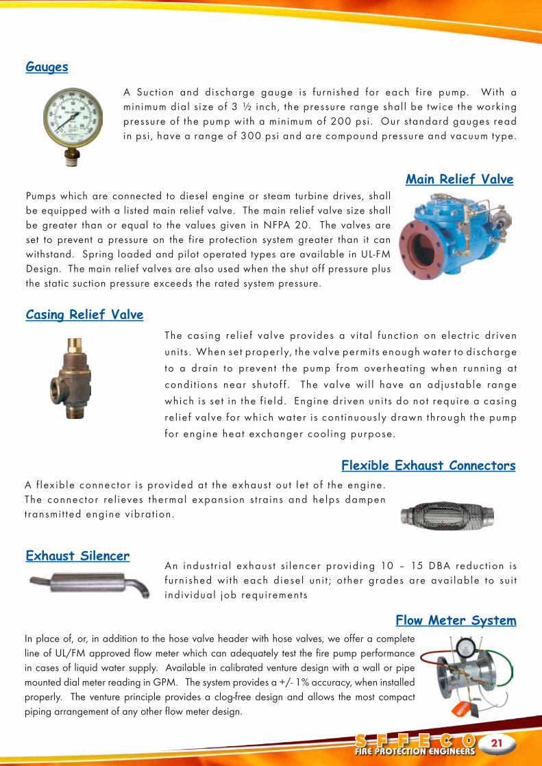
A Suct ion and discharge gauge is furnished for each f i re pump. With a minimum dial s ize of 3 ½ inch, the pressure range shal l be twice the working pressure of the pump wi th a minimum of 200 psi . Our s tandard gauges read in ps i , have a range of 300 psi and are compound pressure and vacuum type.
Pumps which are connected to diesel engine or steam turbine drives, shall be equipped with a listed main relief valve. The main relief valve size shall be greater than or equal to the values given in NFPA 20. The valves are set to prevent a pressure on the fire protection system greater than it can withstand. Spring loaded and pilot operated types are available in UL-FM Design. The main relief valves are also used when the shut of f pressure plus the static suction pressure exceeds the rated system pressure.
The cas ing re l ie f va lve prov ides a v i ta l func t ion on e lec t r ic dr iven
un i t s . When se t proper ly, t he va lve permi t s enough water to d ischarge
to a dra in to prevent t he pump f rom overheat ing when runn ing a t
condi t ions near shu to f f . The va lve wi l l have an adjus table range
which i s se t in t he f ie ld . Engine dr iven un i t s do not requi re a cas ing
re l ie f va lve for which water i s cont inuous ly drawn through the pump
for engine heat exchanger cool ing purpose.
An indus t r ia l exhaus t s i lencer prov id ing 10 – 15 DBA reduct ion i s fu rn i shed wi th each d iese l un i t ; o ther grades are avai lable to su i t ind iv idual job requi rements
A f lex ib le connector i s prov ided a t t he exhaus t ou t le t o f t he engine. The connector re l ieves thermal expans ion s t ra ins and he lps dampen t ransmi t ted engine v ibra t ion .
In place of, or, in addition to the hose valve header with hose valves, we offer a complete line of UL/FM approved flow meter which can adequately test the fire pump performance in cases of liquid water supply. Available in calibrated venture design with a wall or pipe mounted dial meter reading in GPM. The system provides a +/- 1% accuracy, when installed properly. The venture principle provides a clog-free design and allows the most compact piping arrangement of any other flow meter design.
Main Relief Valve
Casing Relief Valve
Exhaust Silencer
Flow Meter System
Flexible Exhaust Connectors
Gauges
www.SFFECO.com22
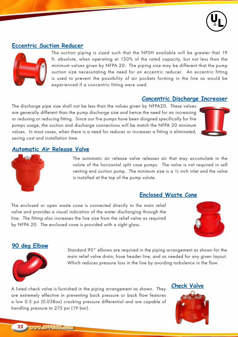
The suction piping is sized such that the NPSH available will be greater that 19 f t. absolute, when operating at 150% of the rated capacity, but not less than the minimum values given by NFPA 20. The piping size may be dif ferent that the pump suction size necessitating the need for an eccentric reducer. An eccentric fitting is used to prevent the possibility of air pockets forming in the line as would be experienced if a concentric fitting were used.
The discharge pipe size shall not be less than the values given by NFPA20. These values are generally different than the pump discharge size and hence the need for an increasing or redusing or reducing fitting. Since our fire pumps have been disigned specifically for fire pumps usage, the suction and discharge connections will be match the NFPA 20 minimum values. In most cases, when there is a need for reducer or increaser a fitting is eliminated, saving cost and installation time.
The automatic air release valve releases air that may accumulate in the volute of the horizontal split case pumps. The valve is not required in self venting end suction pump. The minimum size is a ½ inch inlet and the valve is installed at the top of the pump volute.
Standard 90° elbows are required in the piping arrangement as shown for the main relief valve drain, hose header line, and as needed for any given layout. Which reduces pressure loss in the line by avoiding turbulence in the flow.
The enclosed or open waste cone is connected directly to the main relief valve and provides a visual indication of the water discharging through the line. The fitting also increases the line size from the relief valve as required by NFPA 20. The enclosed cone is provided with a sight glass.
A listed check valve is furnished in the piping arrangement as shown. They are extremely effective in preventing back pressure or back flow features a low 0.5 psi (0.03Box) cracking pressure differential and are capable of handling pressure to 275 psi (19 bar).
Concentric Discharge Increaser
Automatic Air Release Valve
90 deg Elbow
Check Valve
Enclosed Waste Cone
Eccentric Suction Reducer
S F F E C OFIRE PROTECTION ENGINEERS
23
Concentric Discharge Increaser
ORDERING INFORMATION