F-09-000-03.PTO Insp Rep - Muncie Power Products...Locking Collar Dowel Pin (Short) Spring Air Cup...
16
muncie power products, inc. PUMPS COME IN EIGHT POPULAR SIZES FROM 14 TO 40 GPM (53-151 LPM) std. replacement gpm (lpm) max** max max max off mode pump models @ 1,000 rpm rpm psi (bar) vacuum psi (bar) 14 (53) 3,000 3,000 (207) 20 (1.4) 19 (72) 3,000 3,000 (207) 20 (1.4) 23 (87) 3,000 2,500 (172) 20 (1.4) 25 (95) 2,500 2,500 (172) 20 (1.4) 27 (102) 3,000 3,000 (207) 20 (1.4) 31 (117) 3,000 3,000 (207) 20 (1.4) 35 (132) 2,500 2,500 (172) 20 (1.4) PML1-14-01CFSL PML1-19-01CFSL PML1-23-07CFSL PML1-25-01CFSL PMM1-27-07CFSL PMM1-31-07CFSL PMM1-35-07CFSL PMM1-44-07CFSL 40 (151) 2,500 2,500 (172) 5 IN HG (.17 BAR) 5 IN HG (.17 BAR) 5 IN HG (.17 BAR) 5 IN HG (.17 BAR) 5 IN HG (.17 BAR) 5 IN HG (.17 BAR) 5 IN HG (.17 BAR) 5 IN HG (.17 BAR) 20 (1.4) Note: Contact Muncie for specific part number construction or performance data. *Not available for use with Powr-Pro System. **Off mode RPM, 2,500 RPM on mode except PML *25 and PMM *40 which is 2,300 RPM. The 3D diamond-like design appearing on Muncie’s hydraulic pumps is a trademark of Muncie Power Products, Inc., Muncie, Indiana (USA) registered in the United States and various foreign countries. Parts list and service manual POWR-PRO and POWER-MISER L&M SERIES PUMP SYSTEMS DESIGN NO. 1 POWR-PRO POWER-MISER
Transcript of F-09-000-03.PTO Insp Rep - Muncie Power Products...Locking Collar Dowel Pin (Short) Spring Air Cup...

muncie power products, inc.
PUMPS COME IN EIGHT POPULAR SIZES FROM 14 TO 40 GPM (53-151 LPM)
std. replacement gpm (lpm) max** max max max off modepump models @ 1,000 rpm rpm psi (bar) vacuum psi (bar)
14 (53) 3,000 3,000 (207) 20 (1.4)19 (72) 3,000 3,000 (207) 20 (1.4)23 (87) 3,000 2,500 (172) 20 (1.4)25 (95) 2,500 2,500 (172) 20 (1.4)27 (102) 3,000 3,000 (207) 20 (1.4)31 (117) 3,000 3,000 (207) 20 (1.4)35 (132) 2,500 2,500 (172) 20 (1.4)
PML1-14-01CFSL PML1-19-01CFSL PML1-23-07CFSL PML1-25-01CFSL PMM1-27-07CFSL PMM1-31-07CFSL PMM1-35-07CFSL PMM1-44-07CFSL 40 (151) 2,500 2,500 (172)
5 IN HG (.17 BAR) 5 IN HG (.17 BAR) 5 IN HG (.17 BAR) 5 IN HG (.17 BAR) 5 IN HG (.17 BAR) 5 IN HG (.17 BAR) 5 IN HG (.17 BAR) 5 IN HG (.17 BAR) 20 (1.4)
Note: Contact Muncie for specific part number construction or performance data.*Not available for use with Powr-Pro System.
**Off mode RPM, 2,500 RPM on mode except PML *25 and PMM *40 which is 2,300 RPM.The 3D diamond-like design appearing on Muncie’s hydraulic pumps is a trademark of Muncie Power Products, Inc., Muncie, Indiana (USA) registered inthe United States and various foreign countries.
Parts list and service manual
POWR-PRO andPOWER-MISER L&M SERIES PUMP SYSTEMSDESIGN NO. 1
POWR-PRO POWER-MISER

55 77
2 muncie power products, inc.
ITEM QTY PART NUMBER DESCRIPTION
1 1 PM1-10012 1 PM1-1002D3 1 PM1-1003M4 2 PM1-10045 1 PM1-1005M6 1 PM1-1107-CLXXX7 1 PM1-10058 2 PM1-10089 4 PM1-101310 4 PM1-1009M11 2 PM1-1014M
12 1 setPM1-1016-K07-27-2PM1-1016-K07-31-2PM1-1016-K07-35-2PM1-1016-K07-40-2PM1-1016-S05-27-2PM1-1016-S05-31-2PM1-1016-S05-35-2PM1-1016-S05-40-2
13 2 PM1-1015
O.B. Snap RingSpacerSeal RetainerRetainer O-Ring, 2.7x0.103 Inside Shaft SealFront Cover SAE C 4-Bolt Outside Shaft Seal (Reversed) Ring SealBearingsPressure Balance SealWear Plates
Gear sets1¼ in. Round Shaft, 27 GPM 1¼ in. Round Shaft, 31 GPM 1¼ in. Round Shaft, 35 GPM 1¼ in. Round Shaft, 40 GPM 1¼ in. 14T Splined Shaft, 27 GPM 1¼ in. 14T Splined Shaft, 31 GPM 1¼ in. 14T Splined Shaft, 35 GPM 1¼ in. 14T Splined Shaft, 40 GPM Body Seal
ITEM QTY PART NUMBER DESCRIPTION
14 Body (mach. inlet)
15 216 417 118 819 8
20 121 2
27 GPM31 GPM35 GPM40 GPMTest Port Plug, -6 SAEDowel PinKeyWasher, ⅝CapscrewCapscrew, 27 GPM, ⅝-11UNC X 5¼ Capscrew, 31 GPM, ⅝-11UNC X 5½ Capscrew, 35 GPM, ⅝-11UNC X 5¾ Capscrew, 40 GPM, ⅝-11UNC X 6 Rear Cover* (with test ports Str. Thd.) Check Assembly
22 2
1
PM1-1125-27-FIWM PM1-1125-31-FIWM PM1-1125-35-FJCM PM1-1125-40-FJCMHHBP-6ZPM1-1024PM1-1017PE1-1230
PL1-1028-14PL1-1028-16PL1-1028-19PL1-1028-23PM1-1026M PS1-1010BOR-6 O-Ring, 0.47X0.079
note: Torque assembly bolts to 200 ft.lbs. (270Nm)Maximum vacuum is 5 in.Hg. (.17 Bar)
wear plate positionOUTLET (HIGH PRESSURE)
INLET (LOW PRESSURE)
sealdetail
SEAL NOTE:Lip seals, Items #5 (softlip) and #7 (hardlip),must be assembled back to back, as shown.
Service Kits (Part No.)
• Included in Seal Kit (GSK-PM1-PMV)
•,* Included in Rebuild Kit (RBK-PM1-PMV)+ Ring seal slot points toward bearings
1122 77
44
3355
44
66 2121
2121
8899 1010
11111717 1212
●●
●●
●●
●●**
++
●● 1515
1616
16161313●●
14141313
1616
99
1010
882020
18181919
●●
●●
1111**
++1515
2222
2222
M SERIES PUMP SERVICE PARTS
to front of pump
SHAFT
12
5
106
4
3
10
87
12
13
●
●
●
●
*
*
*
*
* *
13*
16 15
17
1117
18
17
14
●
●
*
*
12
9
229
22
19
21
207
●* 8*
muncie power products, inc. 3
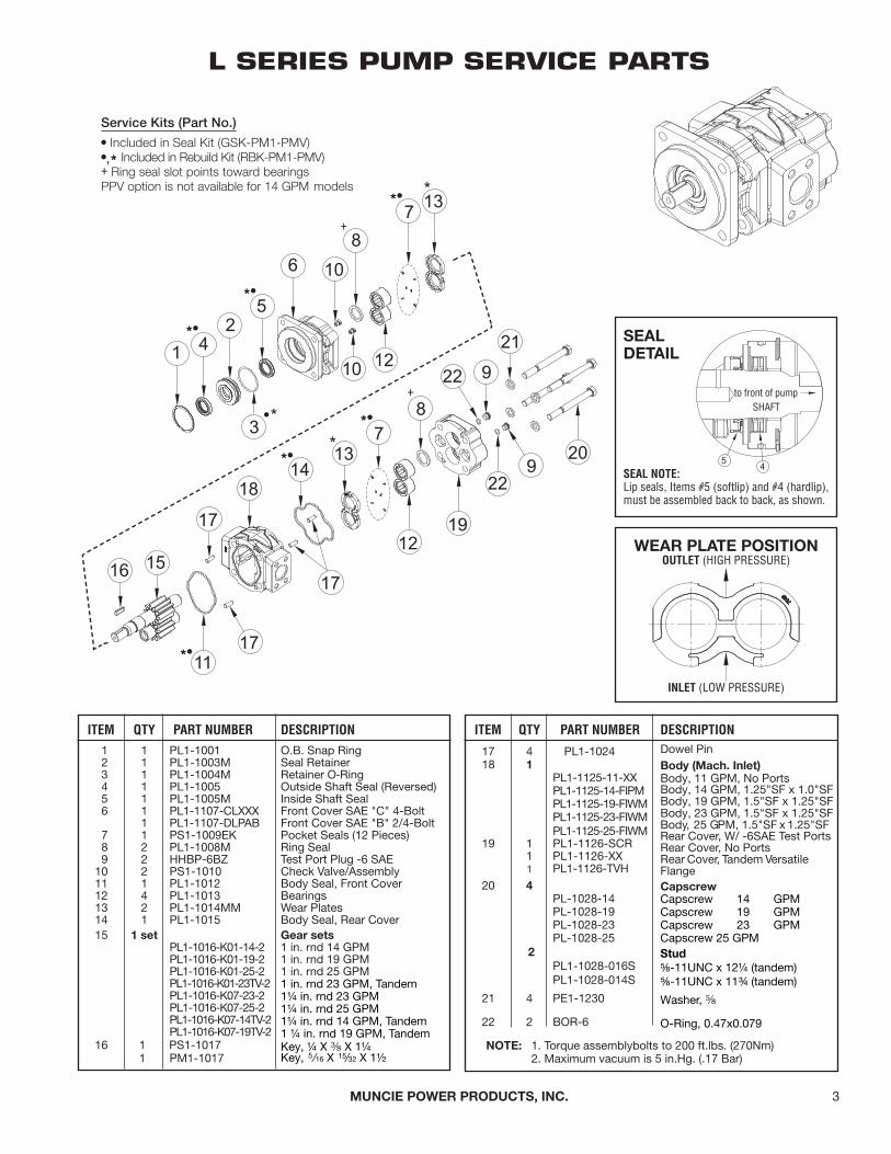
L SERIES PUMP SERVICE PARTS
ITEM QTY PART NUMBER DESCRIPTION1 1 PL1-10012 1 PL1-1003M3 1 PL1-1004M4 1 PL1-10055 1 PL1-1005M6 1 PL1-1107-CLXXX
1 PL1-1107-DLPAB7 1 PS1-1009EK8 2 PL1-1008M9 2 HHBP-6BZ10 2 PS1-101011 1 PL1-101212 4 PL1-101313 2 PL1-1014MM14 1 PL1-101515 1 set
O.B. Snap RingSeal RetainerRetainer O-RingOutside Shaft Seal (Reversed) Inside Shaft SealFront Cover SAE "C" 4-Bolt Front Cover SAE "B" 2/4-Bolt Pocket Seals (12 Pieces) Ring SealTest Port Plug -6 SAE Check Valve/Assembly Body Seal, Front Cover BearingsWear PlatesBody Seal, Rear CoverGear sets
PL1-1016-K01-14-2 1 in. rnd 14 GPMPL1-1016-K01-19-2 1 in. rnd 19 GPMPL1-1016-K01-25-2 1 in. rnd 25 GPMPL1-1016-K01-23TV-2PL1-1016-K07-23-2PL1-1016-K07-25-2PL1-1016-K07-14TV-2PL1-1016-K07-19TV-2
16 1 PS1-10171 PM1-1017
ITEM QTY PART NUMBER DESCRIPTION
17 4 PL1-102418 1
PL1-1125-11-XXPL1-1125-14-FIPMPL1-1125-19-FIWMPL1-1125-23-FIWMPL1-1125-25-FIWM
19 1 PL1-1126-SCR1 PL1-1126-XX1 PL1-1126-TVH
20 4
Dowel PinBody (mach. inlet)Body, 11 GPM, No PortsBody, 14 GPM, 1.25"SF x 1.0"SF Body, 19 GPM, 1.5"SF x 1.25"SF Body, 23 GPM, 1.5"SF x 1.25"SF Body, 25 GPM, 1.5"SF x 1.25"SF Rear Cover, W/ -6SAE Test Ports Rear Cover, No PortsRear Cover, Tandem Versatile Flangecapscrew
PL-1028-14PL-1028-19PL-1028-23PL-1028-25
2
PL1-1028-016S
PL1-1028-014S
21 4 PE1-1230
22 2 BOR-6
Capscrew 14 GPM Capscrew 19 GPM Capscrew 23 GPM Capscrew 25 GPMstud
⅝-11UNC x 12¼ (tandem) ⅝-11UNC x 11¾ (tandem)
Washer, ⅝
O-Ring, 0.47x0.079
note: 1. Torque assemblybolts to 200 ft.lbs. (270Nm)2. Maximum vacuum is 5 in.Hg. (.17 Bar)
wear plate positionOUTLET (HIGH PRESSURE)
INLET (LOW PRESSURE)
sealdetail
SEAL NOTE:Lip seals, Items #5 (softlip) and #4 (hardlip),must be assembled back to back, as shown.
Service Kits (Part No.)
• Included in Seal Kit (GSK-PM1-PMV)
•,* Included in Rebuild Kit (RBK-PM1-PMV)+ Ring seal slot points toward bearings PPV option is not available for 14 GPM models
5 4
to front of pumpSHAFT
*•
*•
*•
*•
*•
*•
+
+
1 in. rnd 23 GPM, Tandem 1¼ in. rnd 23 GPM1¼ in. rnd 25 GPM1¼ in. rnd 14 GPM, Tandem 1 ¼ in. rnd 19 GPM, Tandem Key, ¼ X ⅜ X 1¼Key, 5 ⁄16 X 15⁄32 X 1½

4 muncie power products, inc.
assemBly and disassemBly notes:
1. Removal of the Insert Bushings is not recommended.2. A light coating of grease should be applied to the Valve
Spool before pushing thru O-Rings.3. The Spool and Lockcollar surfaces must be completely
degreased before pressing together. Upon assembly thetotal spool end play should be between .002-.005 inches(.05-.127 mm).
4. The Throttle Plate should be installed from the front side
(Muncie name is cast into this side) in such a way that when rotated to the closed position the edge makes contact with the Dowel Pin. Also be sure that the crossdrilled hole in the Spool lines up with the “P” Port, upon final assembly. Lightly tap the Throttle Plate to allow unit to center itself. Torque Nuts and Screws to 18 in.lbs. (.2 kg-meters).
5. The Air Cylinder should be positioned so that a slightpreload of Throttle Plate, in the closed position, is seen.Torque screws to 105 in.lbs. (1.21 kg-meters).
ITEM QTY PART NUMBER DESCRIPTION
1 1N.A.N.A.
2 1 25T35516
3 1N.A.N.A.
4 2 49T355015 1 N.A.6 1 26T355147 1 27T362388 1 28T362369 1 12T3530410 1 49T3623711 1 26T3559412 2 19T3559513 1 12T3687714 2 N.A.15 2 N.A.
Valve Body
2 inch (50.8 mm) 1½ inch (38.1 mm)Plug
spool2 inch (50.8 mm) 1½ inch (38.1 mm)
Insert Bushing Locking Collar Dowel Pin (Short) SpringAir CupO-Ring (Piston)PistonDowel Pin (Long)Screw (Air Cup)O-Ring (Air Cup)O-Ring (Spool)O-Ring (Insert)
ITEM QTY PART NUMBER DESCRIPTION
16 2 19T35518 Screw17 2 22T35519 Locknut
18 128T3529428T35287
19 112T3686712T36868
20 149T3606649T36067
N.S. 1 N.A.
N.S. 1GSK PPV-32
race2 inch (50.8 mm)1½ inch (38.1 mm)
o-ring (Flange)2 inch (50.8 mm)1½ inch (38.1 mm)
throttle plate2 inch (50.8 mm)1½ inch (38.1 mm)
Dowel Pin (Throttle Plate Stop)
seal Kit2 inch (50.8 mm)*
GSK PPV-24 1½ inch (38.1 mm)**Includes Items 9, 13, 19
N.S. 1 AK-PPV Air Cap KitIncludes Items 7, 8, 9, 10, 11, 13
POWR-PRO SERVICE PARTS
* Air Cap Components(Items 7, 8, 10 & 11)on units built prior to Oct. 1994 cannot be replaced individually and should be replaced with completeKit No. AK-PPV-1.
part numbers shown are for units built after oct. '94. older units are not serviceable except for air components.
PPV-2402 1½" (38.10) Powr-Pro Valve AssemblyPPV-3202 2" (50.80) Powe-Pro Valve Assembly

muncie power products, inc. 5
notes:* a design change has been made on the Power-Miser valve which requires a smaller thickness Air Cylinder O-Ring.For service parts purposes identify by the following:
** requires new style air cylinder o-ring.
style casting no. prefix air cyl. o-ring no. thickness
Old 450X∗∗∗∗ PV-103 .103 in (2.62 mm)
New 352∗∗∗ .070 in (1.77 mm)
This change occurred August, 1989.
CURRENT SUPERSEDEDITEM QTY PART NO. PART NO. DESCRIPTION
1 1 PV-101 — Air Cylinder–– PV-101V –– Air Cylinder (Viton)
2 1 27T35283 PV-102 Spring
3* 1 12T36880 PV-103[.070 (1.77)] [.103 (2.62)]
4 4 19T35279 PV-104-119T35275 PV-104-2
5 4 21T20519 PV-105-121T35276 PV-105-2
6 1 25T35282 PV-106
7 1 01T35271** PV-107-101T35285** PV-107-201T35292** PV-107-3
O-Ring (-017, Viton, 70)
Mtg Bolts -20Mtg Bolts -24 & -32
Lockwasher -20 Lockwasher -24 & -32
Pipe Plug
Body -20Body -24Body -32
POWER-MISER VALVE SERVICE PARTS
CURRENT SUPERSEDEDITEM QTY PART NO. PART NO. DESCRIPTION
8 1 12T36869 PV-108-1 O-Ring -2012T36868 PV-108-2 O-Ring -2412T36867 PV-108-3 O-Ring -32
9 1 28T35273 PV-109-1 Race -2028T35287 PV-109-2 Race -2428T35294 PV-109-3 Race -32
10 1 49T35272 PV-110-1 Plunger -2049T35286 PV-110-2 Plunger -2449T35293 PV-110-3 Plunger -32
11 1 26T35277 PV-111 Cotter Pin
PMV-20 1¼" (31.75) Power-Miser Valve AssemblyPMV-24 1½" (38.10) Power-Miser Valve AssemblyPMV-32 2" (50.80) Power-Miser Valve Assembly
450X∗∗∗∗
12T36880

POWR-PROINSTALLATIONNOTEPOWR-PRO Pump System must have lube line installed and routed back to the reservoir with its own line for proper operation. Do not use a bleed valvewith this system.
6 muncie power products, inc.
POWR-PRO VALVEThe POWR-PRO valve principal is to allow the Hydraulic System to be turned OFF to a low horsepower consumption (Standby) mode. While OFF the crossover lube line directs oil back into a valve chamber to run back to the reservoir. Now, when turned on, full pump flow is available to operate the system, but the lube line passage is now blocked to pre-vent any loss of oil. Lube line pres-sure, when the pump is OFF, must not exceed 20 PSI (1.4 Bar).
POWR-PRO PLUMBING DIAGRAMS
P = PUMPPPV = POWR-PRO VALVEFC = FLOW CONTROL VALVECL = CROSSOVER LINESL = SUCTION LINEPG = TAKE PRESSURE READINGS HERELDL = LUBE DRAIN LINEF = RETURN LINE FILTER
V = DIRECTIONAL CONTROL VALVEC = CYLINDERR = RESERVOIRPL = PRESSURE LINEVG = TAKE VACUUM READINGS HERE
It is recommended that hose between pump outlet, POWR-PRO valve and back to tank, be ⅜" (9.5 mm) ID SAE 100R2 minimum. Maximum recommended vacuum at the inlet of this pump is 5 in.Hg. (.17 Bar).
⅜ (9.5 mm) crossover Hose into “p” port
throttle plateopens/closes
air pistonmoves in/out
pump on port
pump off port
note: powr-pro must be shifted with a 2-position, 4-way valve.
⅜ (9.5 mm) Hose out of “t” port and to the reservoir
cross drilled Holeopens/closes
POWR-PRO“P” Port
POWR-PRO “T” PortMust have ⅜" (9.5 mm) hose routed directly back to the reservoir. Do not hook into any other lines.
⅜" (9.5 mm) Crossover Lube Line
Pump ⅜" (9.5 mm) high pressure port for lube line hookup only. Not to be used for auxiliary systems.

muncie power products, inc. 7
POWER-MISER BLEED-OFF VALVEThe Bleed-Off Valve is required with POWER-MISER and is installed at the top of the reservoir, and routed fromthe pump outlet to prevent accidental pump operation during the Off Mode. Pump pressurization in excess of 20PSI (1.4 Bar) in the Off Mode will result in pump damage. This item must be purchased separately.
POWER-MISER PLUMBING DIAGRAMS
P = PUMPPMV = POWER-MISER VALVEBV = BLEED-OFF VALVE SL = SUCTION LINEPG = TAKE PRESSURE READINGS HERE
F = RETURN LINE FILTERV = DIRECTIONAL CONTROL VALVEC = CYLINDERR = RESERVOIRPL = PRESSURE LINEVG = TAKE VACUUM READINGS HERE
It is recommended that hose between pump outlet and Bleed-Off Valve be ⅜" (9.5 mm) ID SAE 100R2 minimum. Maximum recommended vacuum at the inlet of this pump is 5 in.Hg. (.17 Bar).

8 muncie power products, inc.
POWR-PRO INSTALLATION KITS
POWR-PRO ELECTRIC/AIR SHIFT SYSTEM
POWR-PRO MANUAL/AIR SHIFT SYSTEM
KIT NO. 48M81252 ELECTRIC/AIR SHIFTPARTS LIST AND DESCRIPTION
ITEM QTY PART N0. DESCRIPTION
1 1 44MB2164 Nipple2 1 31M15759 Pressure Protection Valve3 1 44MB6844 Tube Fitting4 1 44MB6842 Tube Fitting5 4 44MB6942 Tube Fitting (elbow)6 1 44MB2252 Street Tee7 1 30M12020 Switch & Light Assy.8 1 35M15002C Solenoid Valve9 1 33T36299 Fuse Holder10 2 34M30006 Terminal Clip11 2 34M18009 Ring Terminal12 1 37T42512 Electrical Wire13 1 45M44430 Air Tubing, 30' (9.14 m)14* 2 34M18187 Female Spade Connector15 1 31M18164 Pressure Switch16 2 44M30137 BreatherN.S. 3 34M18002 Butt Splice
KIT NO. 48M61256 MANUAL/AIR SHIFTPARTS LIST AND DESCRIPTION
ITEM QTY PART N0. DESCRIPTION1 1 44MB21642 1 31M157593 1 44MB68444 2 44MB69425 1 45M444306 1 44MB22527 1 30T602288 1 34T369419 1 35T3795510 1 32M1200111 1 33T3629912 4 34M1800213 1 34M1800914 1 37T42512N.S. 1 36MA1004N.S. 1 36MK1007N.S. 1 36M01453
NipplePressure Protection Valve Tube FittingTube Fitting¼ in. Air Tubing (30 ft.) Street TeePressure Switch Harness PigtailAir ValveLight AssemblyFuse AssemblyButt SpliceRing Terminal18GA Wire (12 ft.)Dash BracketBolt KitFace Plate
note: Solenoid should be mounted in a place that isprotected from harsh weather exposure.
* Include only when EOS-110 is sold with pump.

muncie power products, inc. 9
POWER-MISER INSTALLATION KITS
POWER-MISER ELECTRIC/AIR SHIFT SYSTEM
POWER-MISER MANUAL/AIR SHIFT SYSTEM KIT NO. 48M61255 MANUAL/AIR SHIFTPARTS LIST AND DESCRIPTION
ITEM QTY PART N0. DESCRIPTION
KIT NO. 48M81251 ELECTRIC/AIR SHIFTPARTS LIST AND DESCRIPTION
ITEM QTY PART NO. DESCRIPTION
1 1 35M2X7492 1 30M120203 1 44MB21644 1 31M157595 4 44MB68446 1 44MB68427 2 44MB22548 1 33T362999 2 34M1825010 1 45M4443011 2 34M1800912 1 31M1749C13 1 44MB694214* 2 34M18187
15 1 37T42512 16 1 44M3013717 1 44MB2242
Solenoid Valve (N.0.) Switch & Light AssemblyNipplePressure Protection Valve Tube FittingTube FittingStreet TeeFuse AssemblyTerminal ClipAir Tubing, 30' (9.14 m) Ring TerminalPressure SwitchTube Fitting (elbow) Female Spade Connector(for overspeed light)
Electrical Wire (3.64 m) BreatherAdapterSolenoid Mntg. Kit (NS)
* Include only when EOS-110 is sold with pump.
note: Solenoid should be mounted in a place thatis protected from harsh weather exposure.
1 1 44MB2164 Nipple2 1 31M15759 Pressure Protection Valve3 1 44MB6844 Tube Fitting4 4 44MB6842 Tube Fitting5 1 45M44430 Air Tubing, 30’ (9.14m)6 1 44MB6942 Tube Fitting (elbow)7 1 33T36299 Fuse Assembly8 3 34M18002 Butt Splice9 2 44MB2252 Street Tee10 2 34M18250 Terminal Clip11 1 34M18009 Ring Terminal12 1 32M12001 Light (12 Volt)13 1 35M18653 Air Valve14 1 36MA1004 Dash Bracket15 1 37T42512 Electrical Wire (3.64m)16 1 31M1749C Pressure Switch (N.C.)17 1 44MB2242 Adaptor18 1 36M01005 Face PlateN.S. 1 36MK1007 Bolt Kit
18 1 48TA20038

muncie power products, inc.10
1. Place pump into a vise with drive shaft down. Clamp onto front cover. Using a dark marker or punch,mark all three sections on one side for reference during reassembly. (Figure 1)
2. Remove the 8 cap screws (4 in L Series).
3. Lift off rear cover. If necessary pry loose, but be careful not to damage machined surfaces. (Figure 2)
4. Remove center section with same procedure as above.
5. Remove both the drive and driven gear.
6. Remove wear plates and seals from both the front and rear covers. (Figure 3)
7. Inspect bearings, and if necessary, remove with a bearing puller. (Figure 4)
8. Remove ring seals from the drive gear side front and rear covers. (These should be replaced anytime unit is rebuilt to prevent shaft seal leaks or blowing out.)
9. Rotate front cover in the vise so it faces up, remove snap rings.
10. Remove spacer or outboard bearings with bearing puller. (Figure 5)
11. Tap out shaft seals and discard O-Rings, clean seal retainer with solvent and smooth surface withemery paper. Replace if gouged or nicked at seal area.
PUMP DISASSEMBLY

11muncie power products, inc.
Gear Housings:Wear in excess of .005" (.127 mm) cut-out necessitates replacement of the gear housing. Place a straight-edge across bore. If you can slip a .005" (.127 mm) feeler gauge under the straightedge in the cut-out area, replace the gear housing. Pressure pushes the gears against the housing on the low pressure side. As the hubs and bearings wear, the cut-out becomes more pronounced. Excessive cutout in a short period of time indicates excessive pressure or oil contamination. If the relief valve settings are within prescribed limits, check for shock pres-sures or tampering. Withdraw oil sample and check it and tank for dirt.
Gears:Replace if there is any wear detectable by touch in the seal areas or at the drive coupling. .002" (.05 mm) wear is the maximum allowable. Wear in the shaft seal areas indicate oil contamination and shaft replacement is required. Wear or damage to splines keys or keyways necessitates replacement. Any wear on the hubs detectable by touch, or in excess of .002" (.05 mm) necessitates replacement. Nicking, grooving, fretting of teeth surfaces or head discoloration also necessitates replacement. Scoring, grooving or burring of outside diameter of teeth generally means replacement is necessary unless damage is light and can be stoned off. Maximum shaft runout is .001" (.025 mm).
Wear Plates:The wear plates seal the gear section at the sides of the gears. Wear here will allow internal slippage, that is, oil will bypass within the pump. A .002" (.05 mm) maximum wear is allowable. Replace wear plates if they are scored, eroded, pitted or discolored. Check the center wear plates where the gears mesh. Erosion here indicates oil contamination. Pitted thrust plates indicate cavitation or oil aeration. Discolored wear plates indicate over-heating, probably insufficient oil.
Seals and Gaskets:Replace all rubber polymer seals, and shaft ring seals, whenever disassembling pump. Include all O-Rings, pocket seals behind wear plates, shaft seal and gasket seals.
Bearings:If gears are replaced, bearings must be replaced. Bearings should fit into bore with a light press fit. A neat hand fit is allowable. If bearings can fall out, bore may be oversize.
Dowel Pins:If either the dowel pin or dowel hole is damaged, the pin or machined casting, or both, must be replaced. If more than reasonable force is required to seat dowels the cause may be poorly deburred or dirty parts; cocking of the dowel in the hole, or improper pin-to-hole fit.
Check Valves:Examine small check valves in shaft end cover to make sure they are intact and functioning. If there are no check valves here, make sure the high pressure side of the shaft end cover is plugged.
PARTS INSPECTIONtHe FollowinG is a Guide in eValuatinG parts to see iF replacement is needed

muncie power products, inc.12
1. Place front cover face down in vise. Stone off outer edge to remove any burrs produced from disassembly.Reclean. (Figure 1)
2. Insert new ring seal with NOTCH visible. Re-install bearing, using arbor press until it bottoms.3. Install wearplates and seals onto bearings. Note that pocket seals (L Series) need to have center seals installed
first (Hold in place with grease). Outer seals can be slid into position (and cut to length) with wearplatesinstalled. (Figure 2)
4. Install the gears until they bottom against the wearplates.5. Grease the body O-Rings and install into the groove in the center section. Install the same way as removed by
aligning the marks. (NOTE: Any burrs should have been stoned off prior to reassembly.) (Figure 3)6. Remove any burrs from the rear cover and clean.7. Insert ring seal and bearings as described in step 2.8. Install wearplates as described in step 3. (Figure 4)9. Install rear cover onto pump housing by aligning the marks. Lightly tap into place. (Figure 5)
10. Install the 8 cap screws. Snug up the bolts using a criss cross pattern. Rotate the drive shaft with a 6" wrenchto make sure there is no binding. Now torque the bolts [M Series is 200 ft.lbs. (27.6 kg-meters), L Series is 225ft.lbs. (31.1 kg-meters)] using the criss cross pattern again.
11. Rotate pump onto work bench face up. Install the new shaft seals into the seal retainer (Reference service partspage for proper position); using Permatex aviation form a gasket sealer on the outside seal casing.
12. Grease O-Rings and install onto retainer.13. Using a greased seal guide (L Series Part No. A-1254-5, M Series Part No. A-1254-6) on the drive shaft, install
the seal retainer (O-Rings first) into the pump.14. Drop in spacer or outboard bearing and install snap ring.
PUMP REASSEMBLYBased on needed parts HaVinG Been replaced and all otHer parts tHorouGHly cleaned
13muncie power products, inc.
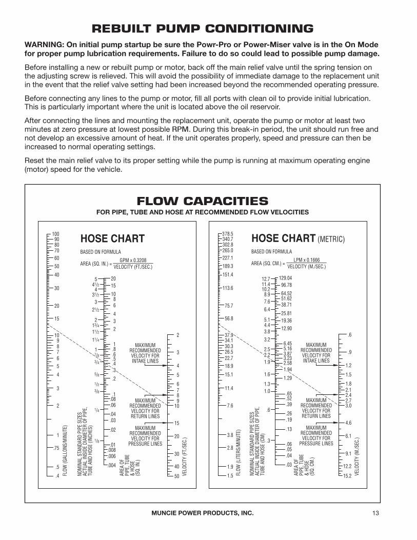
REBUILT PUMP CONDITIONINGwarninG: on initial pump startup be sure the powr-pro or power-miser valve is in the on mode for proper pump lubrication requirements. Failure to do so could lead to possible pump damage.
Before installing a new or rebuilt pump or motor, back off the main relief valve until the spring tension on the adjusting screw is relieved. This will avoid the possibility of immediate damage to the replacement unit in the event that the relief valve setting had been increased beyond the recommended operating pressure.
Before connecting any lines to the pump or motor, fill all ports with clean oil to provide initial lubrication. This is particularly important where the unit is located above the oil reservoir.
After connecting the lines and mounting the replacement unit, operate the pump or motor at least two minutes at zero pressure at lowest possible RPM. During this break-in period, the unit should run free and not develop an excessive amount of heat. If the unit operates properly, speed and pressure can then be increased to normal operating settings.
Reset the main relief valve to its proper setting while the pump is running at maximum operating engine(motor) speed for the vehicle.
FLOW CAPACITIESFor pipe, tuBe and Hose at recommended Flow Velocities
HOSE CHART
BASED ON FORMULA
AREA (SQ. IN.) =GPM x 0.3208
VELOCITY (FT./SEC.)
AREA
OF
PIPE
, TUB
E&
HOSE
(SQ.
IN.)
NOM
INAL
STA
NDAR
D PI
PE S
IZES
ACTU
AL IN
SIDE
DIA
MET
ER O
F PI
PE,
TUBE
AND
HOS
E (IN
CHES
)
10090807060
50
40
30
20
15
1098765
4
3
2
1
.75
.5
.4 FLOW
(GAL
LONS
/MIN
UTE)
.3
20515
1086
432
1.8.6.5.4
.2
.1.08.06
.04
.03
.02
.01.008.006
.004
41/24
31/2
321/2
213/4
11/2
11/4
17/8
3/4
3/8
1/4
1/8
5/8
1/2
VELO
CITY
(FT./
SEC.
)
2
3
4
5
6789
10
15
20
30
40
50
MAXIMUMRECOMMENDEDVELOCITY FORINTAKE LINES
MAXIMUMRECOMMENDEDVELOCITY FORRETURN LINES
MAXIMUMRECOMMENDEDVELOCITY FOR
PRESSURE LINES
LPM x 0.1666VELOCITY (M./SEC.)
HOSE CHART (METRIC)BASED ON FORMULA
AREA (SQ. CM.) =
AREA
OF
PIPE
, TUB
E&
HOSE
(SQ.
CM
.)
NOM
INAL
STA
NDAR
D PI
PE S
IZES
ACTU
AL IN
SIDE
DIA
MET
ER O
F PI
PE,
TUBE
AND
HOS
E (C
M)
FLOW
(LIT
ERS/
MIN
UTE)
VELO
CITY
(M./S
EC.)
MAXIMUMRECOMMENDEDVELOCITY FORINTAKE LINES
MAXIMUMRECOMMENDEDVELOCITY FORRETURN LINES
MAXIMUMRECOMMENDEDVELOCITY FOR
PRESSURE LINES
378.5340.7302.8265.0227.1
189.3
151.4
113.6
75.7
56.8
37.934.130.326.522.718.9
15.1
11.4
7.6
3.8
2.8
1.9
1.5
129.0412.796.78
64.5251.6238.71
25.8119.3612.90
6.455.163.873.232.58
1.29
.65
.52
.39
.26
.19
.13
.06
.05
.04
.03
11.410.28.97.66.4
5.14.43.83.2
2.5
1.9
1.0
.6
.3
1.6
1.3
1.94
2.2
12.2
15.2
.6
.9
1.2
1.5
1.82.12.42.73.0
4.6
6.1
9.1

muncie power products, inc.14
possiBle pump trouBles
I. Pump unusually noisy (ON)
Pump unusually noisy (OFF)
II. Pump fails to respond
III. Oil heating up (ON)
Oil heating up (OFF)
causes
A — Low supply of oilB — Heavy oilC — Dirty oil filterD — Suction line too smallE — Restriction in suction lineF — Air leak in suction lineG — Oil temperature extremely high
causing vapor to form in the oilH — Pump sucking air through the
shaft oil seal when pump is idling
I — Excessive pressure build-up in the Off Mode
A — Low oil supplyB — Insufficient relief valve pressureC — Pump worn or damagedD — POWR-PRO or POWER-MISER
valve not shifting
A — Foreign matter lodged betweenrelief valve plunger and relief valve seat
B — Using very light oil in hot climateC — Dirty oilD — Oil level too lowE — Insufficient relief valve pressureF — Relief valve pressure too highG — Pump worn (slippage)H — Excessive pressure build-up in the
Off Mode
remedies
A — Fill to proper levelB — Change to proper oilC — Clean and replace filterD — Increase size of suction lineE — RemoveF — Check for loose connectionG — Check entire circuit
H — Check by squirting oil around the seal— Replace if faultyI — Install Bleed-Off Valve (POWER-MISER)— Replace damaged Bleed-Off Valve (POWER-MISER)
— Check hose routing/damage— Blockage in POWR-PRO valve— POWR-PRO throttle plate misadjusted and won’t close
A — Fill to proper levelB — Reset to correct pressure setting using gaugeC — Inspect, repair or replaceD — Inspect air cylinder & air activation system
A — Inspect and remove foreign matter
B — Drain and refill with proper oilC — Drain, flush, and refill with clean oilD — Fill to proper levelE — Set to correct pressureF — Same as “E”G — Replace or repairH — Install Bleed-Off Valve (POWER-MISER)— Replace damaged Bleed-Off Valve (POWER-MISER)
— Check hose routing/damage— Blockage in POWR-PRO valve— POWR-PRO throttle plate misadjusted and won’t close
TROUBLE SHOOTING GUIDE FOR HYDRAULICSHydraulic analysis and proper repair require the use of a vacuum gauge and pressure gauge for testing.
Ports are provided in rear cover for testing.
OIL RECOMMENDATIONSMuncie does not promote specific manufacturers’ brands of oil. Specifications below are guidelines and the oil manufacturershould be consulted for your exact application needs.
Viscosity (ASTM D-88-56) — @ 100° F (40° C)-173/187 SSU (37 CS)[Ref. 210° F (100° C) - Approx. 45 SSU (5.9 CS) Minimum] Viscosity
Index (ASTM D-567-53) — 100° F (82° C) Optimum Gravity °API (ASTM D-287-64) — 29° F (-2° C) MinimumFlash Point (ASTM D-92-57) — 400° F (204° C) MinimumFire Point (ASTM D-92-57) — 430° F (221° C) Minimum (Ref.)Pour Point (ASTM D-97-57) — 15° F (-10° C) Maximum
Foam Resistance (ASTM D-892, Test. Seq. II)Viscosity at Startup [7,500 SSU (1,620 CS) Maximum]Rust Resistance (ASTM D-665-60) — No Rust Corrosion Resistance (ASTM D-130-65) — Class. 1 Oxidation Stability (ASTM D-943) — 1,500 Hours Min. Aniline Point (ASTM D-611-64) — 180–220° F (82–104° C) Anti-Wear Additive — .06% Zinc Minimum
note: Cold weather operation requires special oil considerations. Viscosity should not exceed 7,500 SSU (1,620 CS) at loweststartup temperature. Continuous operation should range between 60–1,000 SSU (10.5–216 CS) for all temperature ranges. Never use Diesel fuel or kerosene to thin the oil.

NOTES
15

201 East Jackson Street • Muncie, Indiana 47305800-367-7867 • Fax 765-284-6991 • [email protected] • www.munciepower.com
Specifications are subject to change without notice. Visit www.munciepower.com for warranties and literature. All rights reserved. © Muncie Power Products, Inc. (2011)A Member of the Interpump Group
SP11-01 (08-19)