EZ-8 Sander - Floor Sanding Equipment MN...CAUTION: Serious damage to the floor can occur if the...
22
Form No 78599C 2/07 Printed in the U.S.A. READ THIS BOOK This book has important information for the use and safe operation of this machine. Failure to read this book prior to operating or attempting any service or maintenance procedure to your Clarke American Sanders machine could result in injury to you or to other personnel; damage to the machine or to other property could occur as well. You must have training in the operation of this machine before using it. If your operator(s) cannot read this manual, have it explained fully before attempting to operate this machine. All directions given in this book are as seen from the operator’s position at the rear of the machine. For new books write to: Clarke ® , 2100 Highway 265, Springdale, Arkansas 72764 EZ-8 Sander Operator's Manual
Transcript of EZ-8 Sander - Floor Sanding Equipment MN...CAUTION: Serious damage to the floor can occur if the...

Form No 78599C 2/07 Printed in the U.S.A.
READ THIS BOOK
This book has important information for the use and safe operation of this machine. Failure to readthis book prior to operating or attempting any service or maintenance procedure to your ClarkeAmerican Sanders machine could result in injury to you or to other personnel; damage to the machineor to other property could occur as well. You must have training in the operation of this machinebefore using it. If your operator(s) cannot read this manual, have it explained fully before attemptingto operate this machine.
All directions given in this book are as seen from the operator’s position at the rear of the machine.
For new books write to: Clarke® , 2100 Highway 265, Springdale, Arkansas 72764
EZ-8Sander
Operator'sManual

Page 2 Clarke® American Sanders EZ - 8 Sander Operator's Manual
Operator Safety Instructions .........................................................3Introduction and Machine Specifications .......................................5How to Transport the Machine ......................................................6Machine Set-Up ...........................................................................7How to Operate the Machine ........................................................9Sanding Cuts and Sandpaper ....................................................10Sander Adjustment Procedures ..................................................11Routine Maintenance..................................................................12Troubleshooting .........................................................................13
Section II Parts and Service ManualAssembly Drawing #1 ................................................................16Assembly Parts List #1 ..............................................................17Assembly Drawing #2 ................................................................18Assembly Parts List #2 ..............................................................19Wiring Diagram..........................................................................20
Contents of this Book

Clarke® American Sanders EZ - 8 Sander Operator's Manual Page 3
DANGER means: Severe bodily injury or death can occur to you or other personnel if the DAN-GER statements found on this machine or in this Operator's Manual areignored or are not adhered to. Read and observe all DANGER statementsfound in this Operator's Manual and on your machine.
WARNING means: Injury can occur to you or to other personnel if the WARNING statementsfound on your machine or in this Operator's Manual are ignored or are notadhered to. Read and observe all WARNING statements found in thisOperator's Manual and on your machine.
CAUTION means: Damage can occur to the machine or to other property if the CAUTION state-ments found on your machine or in this Operator's Manual are ignored or arenot adhered to. Read and observe all CAUTION statements found in thisOperator's Manual and on your machine.
DANGER: Failure to read the Operator's Manual before operating or servicing this sanding equipmentcould result in injury to the operator or to bystanders and could cause damage to theequipment. Read and observe all safety statements found in this manual and on thesanding equipment. Make sure all labels, decals, warnings, cautions and instructions arefastened to the equipment. Replace any that are damaged or missing. You must havetraining in the operation of this equipment before using it. If the operator is unable toread this manual, have it explained fully before they attempt to use this equip-ment.
DANGER: Sanding/finishing wood floors can create an environment that can be explosive. Thefollowing safety procedures must be adhered to:
• Cigarette lighters, pilot lights and any other source of ignition can create an explosionwhen active during a sanding session. All sources of ignition should be extinguished orremoved entirely if possible from the work area.
• Work areas that are poorly ventilated can create an explosive environment when certaincombustible materials are in the atmosphere, i.e., solvents, thinners, alcohol, fuels,certain finishes, wood dust and other combustible materials. Floor sanding equipmentcan cause flammable material and vapors to burn. Read the manufacturer's label on allchemicals used to determine combustibility. Keep the work area well ventilated.
• Spontaneous combustion or an explosion can occur when working with sanding dust.The sanding dust can self-ignite and cause injury or damage. Sanding dust should bedisposed of properly. Always empty the sanding dust into a metal container that islocated outside of any building(s).
• Remove the contents of the dust bag when the bag is 1/3 full. Remove the contents ofthe dust bag each time you finish using the equipment. Never leave a dust bag unat-tended with sanding dust in it.
• Do not empty the contents of the dust bag into a fire.
• Hitting a nail while sanding can cause sparks and create an explosion or fire. Alwaysuse a hammer and punch to countersink all nails before sanding floors.
OPERATOR SAFETY INSTRUCTIONS

Page 4 Clarke® American Sanders EZ - 8 Sander Operator's Manual
DANGER: Operating partially assembled sanding equipment could result in injury to the operator orbystander and could cause damage to the equipment or to other property.
• Do not operate this equipment unless it it fully assembled and all guards, doors and coversare secured.
• Keep all fasteners tight.
• Keep all adjustments within manufacturers specifications.
DANGER: Moving parts on this sanding equipment can cause injury to the operator or bystanders.
• Keep hands, feet and loose clothing away from all moving parts.
• Do not change or adjust the abrasive while the sanding equipment is running.
• Do not service the sanding equipment while it is running.
DANGER: This sanding equipment requires a supply of electricity. Improper use could result in electricalshock or fire.
• Connect only to an electrical source matching what is shown on the equipment nameplate.
• Do not use this sanding equipment on an ungrounded electrical circuit. Consult an electricianif you suspect the circuit is not properly grounded.
• Do not use this sanding equipment with a damaged electrical cord. Inspect before each use.
• Avoid striking the elelctrical cord with the abrasive. Always lift the electrical cord over thesanding equipment.
• Do not use the electrical cord to move the sanding equipment.
• Disconnect the electrical source before servicing this equipment.
WARNING: In the event of a bag fire, injury can occur to the operator if the operator is tied or strapped to equipment.Use operating belt properly ( follow procedure on page 11).
WARNING: Injury to the operator or bystander can occur if protective gear is not worn while sanding. Alwaysuse eye, ear, and respiratory protection while performing any sanding operation.
WARNING: Bodily injury could occur if power is applied to the equipment with the power switch already in the"ON" position. Always check to assure that the power switch is in the "OFF" position beforeconnecting power supply.
CAUTION: Maintenance and repairs performed by unauthorized personnel could result in damage or injury.Maintenance and repairs performed by unauthorized personnel will void your warranty. Servicingof this unit must always be referred to an authorized Clarke American Sanders distributor.
CAUTION: Use of this equipment to move other objects or to climb on could result in injury or damage. Do notuse this equipment as a step or furniture. Do not ride on this equipment.
CAUTION: Damage could occur to the equipment if not properly kept in a dry building for storage. Store theequipment in a dry building.
CAUTION: The equipment is heavy. When transporting the equipment, remove the motor. Get help to lift theequipment and motor.
CAUTION: Serious damage to the floor can occur if the sanding equipment is left running in one spot whilethe sanding drum is in contact with the floor. To avoid damage to the floor, feather cut in at a normalsanding rate. Do not dwell while lowering or raising the contact wheel. Always sand at a constantrate.

Clarke® American Sanders EZ - 8 Sander Operator's Manual Page 5
Introduction & Machine Specifications
CAUTION: Your equipment may be inappropriate on some installations. Always consult with the flooring manufacturer on the proper installation, preparation, and finishing of their product. Determine suitability of your equipment in preparing the product.
Voltage/Frequency 110-120V / 50 Hz 220-240V / 50 Hz 220-240V / 50 HzAmperage 12.0 6.0 6.0Sound Level 84 dB(A) 84 dB(A) 84 dB(A)Vibration 7.4m/s2 7.4m/s2 7.4m/s2
Abrasive Size 203x487mm 203x487mm 203x482mmsheet sheet sleeve
Abrasive Rate 680m/min 680m/min 720m/minDrum Rate 1500 RPM 1500 RPM 1500 RPMDust Control Rate 30.2l/sec 30.2l/sec 30.2l/secDrum Pressure 11.4kg 11.4kg 11.4kgLeveling Controls Externally Externally Externally
Adjustable Adjustable AdjustablelOperating Controls Lever Lever Lever
Operated Operated OperatedMotor 1.1KW TEFC 1.1KW TEFC 1.1KW TEFC
Thermally Thermally ThermallyProtected Protected Protected
Power Cable 12m 3x2.5mm2 12m 3x2.5mm2 12m 3x2.5mm2
Abrasion Abrasion AbrasionResistant Resistant Resistant
Dimensions (mm)* 546x406x902 546x406x902 546x406x902Weight * 58kg 58kg 58kg
*Shipping Value
OperatingControl Lever
Control Switch
Control Link
Transport Handle
Dust Pipe
Locking Collar
Handle Latch
Level Adjustment Drum Cover

Page 6 Clarke® American Sanders EZ - 8 Sander Operator's Manual
How to Transport the Machine
Transporting the Machine With LimitedCargo Area:
To transport the machine, follow this procedure:
1. Lower sanding drum with control lever. Seefigure 1.
2. Slide collar beyond overlap of control link; removepin from notch. See figure 2.
3. Twist and remove handle pigtail from motor cord.See figure 3.
4. Release handle latches and remove handle fromchassis. See figure 2.
5. Remove dust pipe from chassis.
6. Lift chassis with transport handles and place incargo area. See figure 4.
WARNING: Machine is heavy (43.2kg). Toavoid injury or damage grasptransport handles firmly; useproper lifting technique.
7. Secure chassis to prevent movement in cargo area.Place handle and dust pipe in cargo area.
Figure 2
Figure 3
Figure 1
Figure 4

Clarke® American Sanders EZ - 8 Sander Operator's Manual Page 7
Machine Set-up
To set up the machine follow this procedure:
1. Familiarize yourself with the machine. Read alldanger, warning, and caution statements as wellas the Operator's Manual. If operator is unableto read English, have the manual explainedbefore operating.
2. Install handle and fasten latches. See figure # 6.
3. Insert control link into notch and slide collar topin. Raise sanding drum with control lever. Seefigure # 5 & # 6.
4. Install dust tube.
5. Connect the handle pigtail to the motor cord.Align ground pin, insert and twist. See figure # 7.
6. To install abrasive on sanding drum equippedwith paper clamp: loosen screws to paper clampwith a coin. Do not remove screws or clampfrom the sanding drum. Insert one edge ofabrasive under paper clamp. Rotate sandingdrum to wrap abrasive around drum. Insert otheredge of abrasive under paper clamp. Centerabrasive and take up any slack in the abrasive.Tighten screws on paper clamp. Close drumcover. See figure # 8.
To install abrasive on sanding drum equipped forsleeve abrasive: slide abrasive over drum, centerabrasive, and close drum cover.
Figure # 5
Figure # 6
Figure # 7
Figure # 8

Page 8 Clarke® American Sanders EZ - 8 Sander Operator's Manual
MACHINE SET-UP
7. This sanding machine is designed to be operatedwith a remote vacuum dust collection system orwith the included dust bag. Follow the proceduresbelow:
Preparing Remote Vacuum Dust Collection Systems
To prepare the machine for remote vacuum dust collectionsystems that have a 2" hose end, follow this procedure:
1. Install 2" hose end (figure 9, A) directly over theexhaust tube (figure 9, B).
2. The exhaust tube can be rotated for optimum conve-nience.
To prepare the machine for remote vacuum dust collectionsystems that have a 1 ½" hose end, follow this procedure:
1. Install the 2" x 1½" hose end adaptor (Part No.30563A) (figure 9, C) over the exhaust tube (figure 9,B).
2. Insert 1 ½" hose end (figure 9, D) into the adaptor(figure 9, C).
NOTE: Start the remote vacuum collection systembefore operation.
Preparing to use the included dust bag
To prepare the machine for use with the included dust bag,follow this procedure:
1. Install the dust bag by pressing the end onto theexhaust tube until the ring locks into the groove (figure10). This is best done by pressing on the back of thebag opening with the palm of your hand.
2. The exhaust tube can be rotated for optimum conve-nience.
3. To remove the dust bag from the exhaust tube, pry upthe end of the bag opening to partially release theinternal rib from the groove, then pull.
4. To empty the dust bag, unzip the disposal flap andforce contents out by inverting the bag.
NOTE: For best results, empty frequently. Follow allwarnings posted in this manual and on the dust bag.
Install the dust bag bypressing the end onto theexhaust tube until the ringlocks into the groove.
1.5" Hose fromvacuum system
(not included)
BCExhaust Tube
(30563A)2" Tube x 1.5" hose adaptor
Figure 9
Figure 10
A2" Hose fromvacuum system(not included)
D

Clarke® American Sanders EZ - 8 Sander Operator's Manual Page 9
How to Operate the Machine
To operate the machine follow this procedure:
1. Set any exposed nails with a hammer and punchto avoid encounter with sanding drum. Connectthe machine to an appropriate grounded andfused circuit (power supply). Press the selectorswitch to the start (S) position. Once started,allow switch to return to run (R) position.
CAUTION: To prevent damage to the surface,make sure the machine is alwaysmoving when the sanding drum isin contact with the floor.
2. Work right to left. For each forward pass, movethe machine 4" over the pass you have justfinished. Retrace your reverse path withoutoverlapping. See figure # 11
3. Feather-cut in by easing the sanding drum downonto the surface with the control lever while thesander is in motion.
4. When sanding drum is fully engaged with thesurface, release control lever and adjust yourpace for adequate stock removal. Keep sanderin motion while the sanding drum is engaged withthe surface or dwell marks will occur.
5. Move the machine in the direction of the grain inthe wood whenever possible. Sand the surfaceat a constant pace.
6. Gradually feather-cut out at the termination point(the end of your pass) by easing the sandingdrum up with the control lever. Stagger thetermination points for a better blend whenedging. See figure # 11.
7. When replacing abrasive, emptying contents ofdust bag, or when sanding operation is com -pleted, press selector switch to off (O) position.Disconnect the machine from the power supply.
8. Empty dust bag whenever it is 1/3 full. Neverleave a dust bag unattended with sanding dust init. Sanding dust can spontaneously ignite andcause a fire or explosion. Empty dust into ametal container clear of any combustible mate-rial.
Figure 11
1
3
2
4
Page 10 Clarke® American Sanders EZ - 8 Sander Operator's Manual
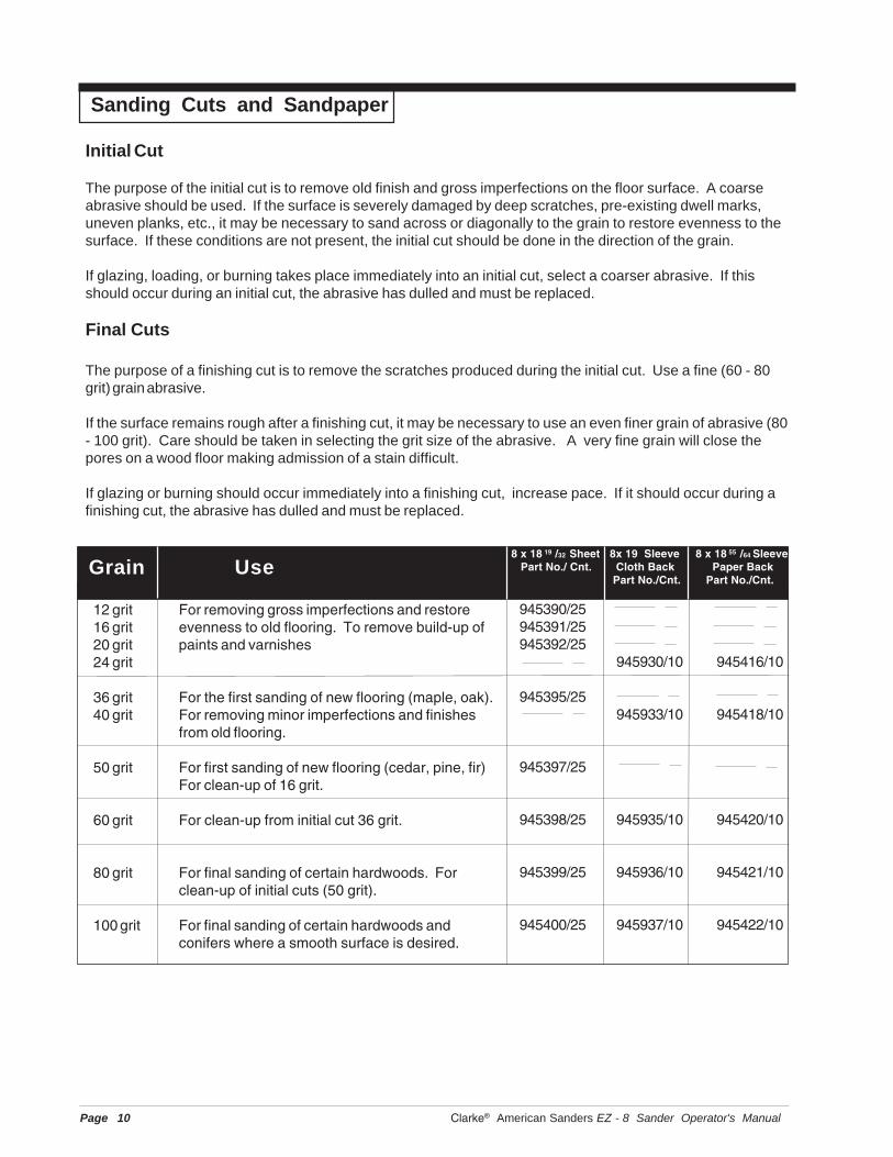
945390/25945391/25945392/25
945930/10 945416/10
945395/25945933/10 945418/10
945397/25
945398/25 945935/10 945420/10
945399/25 945936/10 945421/10
945400/25 945937/10 945422/10
Sanding Cuts and Sandpaper
12 grit For removing gross imperfections and restore16 grit evenness to old flooring. To remove build-up of20 grit paints and varnishes24 grit
36 grit For the first sanding of new flooring (maple, oak).40 grit For removing minor imperfections and finishes
from old flooring.
50 grit For first sanding of new flooring (cedar, pine, fir)For clean-up of 16 grit.
60 grit For clean-up from initial cut 36 grit.
80 grit For final sanding of certain hardwoods. Forclean-up of initial cuts (50 grit).
100 grit For final sanding of certain hardwoods andconifers where a smooth surface is desired.
Grain Use
Initial Cut
The purpose of the initial cut is to remove old finish and gross imperfections on the floor surface. A coarseabrasive should be used. If the surface is severely damaged by deep scratches, pre-existing dwell marks,uneven planks, etc., it may be necessary to sand across or diagonally to the grain to restore evenness to thesurface. If these conditions are not present, the initial cut should be done in the direction of the grain.
If glazing, loading, or burning takes place immediately into an initial cut, select a coarser abrasive. If thisshould occur during an initial cut, the abrasive has dulled and must be replaced.
Final Cuts
The purpose of a finishing cut is to remove the scratches produced during the initial cut. Use a fine (60 - 80grit) grain abrasive.
If the surface remains rough after a finishing cut, it may be necessary to use an even finer grain of abrasive (80- 100 grit). Care should be taken in selecting the grit size of the abrasive. A very fine grain will close thepores on a wood floor making admission of a stain difficult.
If glazing or burning should occur immediately into a finishing cut, increase pace. If it should occur during afinishing cut, the abrasive has dulled and must be replaced.
8 x 18 19 /32 Sheet 8x 19 Sleeve 8 x 18 55 /64 Sleeve Part No./ Cnt. Cloth Back Paper Back
Part No./Cnt. Part No./Cnt.

Clarke® American Sanders EZ - 8 Sander Operator's Manual Page 11
Sander Adjustment Procedures
DANGER: Electrocution could occur if main-tenance and repairs are performedon a unit that is not properly dis-connected from the power source.Disconnect the power supply be-fore attempting any maintenanceor service.
DANGER: Moving parts of this machine cancause serious injury and/or dam-age. Keep hands, feet and looseclothing away from all moving partsof the sander.
The following information provides details on how toadjust different features/controls of the sander.
Dust Shoe
To adjust the dust shoe follow this procedure:
1. Disconnect machine from power supply.
2. Loosen the four screws fastening the dust shoe tothe chassis.
3. Adjust the dust shoe towards the drum to improverecovery of fine particles.
4. Adjust the dust shoe away from the drum toimprove recovery of coarse particles.
5. Align the dust shoe with the drum and tightenscrews. See figure 12.
Leveling
To adjust the machine leveling follow this procedure:
1. Locate the leveling screw. See figure 13.
2. Tighten the screw (compress the leveling spring)to sand heavier on drive belt side of sanding drum.
3. Loosen the leveling screw (relax the levelingspring) to sand heavier on the side opposite thedrive belts.
Figure 12
Figure 13

Page 12 Clarke® American Sanders EZ - 8 Sander Operator's Manual
Routine Maintenance
The following items need to be periodically inspectedand maintained to keep your sander in good workingcondition.
Sanding Chamber
Periodically blow out the sanding chamber to preventlarge accumulations of debris which could interferewith the performance of the dust recovery system.
Wheels
Periodically remove the debris from the truck andcaster wheels. Debris can cause waves on a sandedsurface.
Dust Bag
Remove the dust bag from the machine and shake itthoroughly to remove the sanding dust from the dustbag. Turn the dust bag inside out and machine washin cold water to prevent pore blockage and loss ofdust recovery.
Drive Belt
Periodically check the drive belts for broken cogs orfrayed edges. Frayed edges may indicate poortracking. Realign effected belt.
Bearings
Periodically check the bearings for wear ordamage according to the following schedule:
Arbor shaft Relubricate every 150 hrs.w/.10 oz. of a NLGI grade2, -300F to 2500F, 58-75SUS at 2100 F, greaselubricant.
Motor shaft after 1st 5000 hrs.
Fan shaft After first 1500 hrs.
Clarke® American Sanders EZ - 8 Sander Operator's Manual Page 13
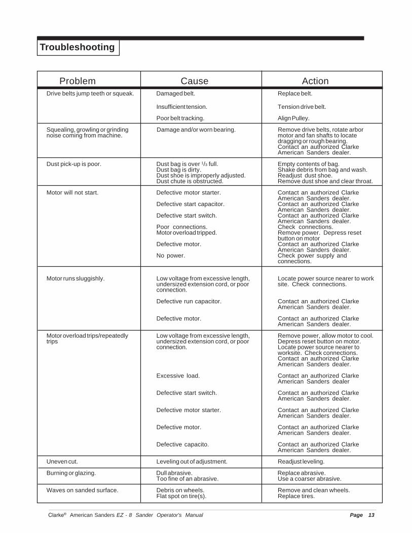
Troubleshooting
Problem Cause ActionDrive belts jump teeth or squeak. Damaged belt. Replace belt.
Insufficient tension. Tension drive belt.
Poor belt tracking. Align Pulley.
Squealing, growling or grinding Damage and/or worn bearing. Remove drive belts, rotate arbornoise coming from machine. motor and fan shafts to locate
dragging or rough bearing.Contact an authorized ClarkeAmerican Sanders dealer.
Dust pick-up is poor. Dust bag is over 1/3 full. Empty contents of bag.Dust bag is dirty. Shake debris from bag and wash.Dust shoe is improperly adjusted. Readjust dust shoe.Dust chute is obstructed. Remove dust shoe and clear throat.
Motor will not start. Defective motor starter. Contact an authorized ClarkeAmerican Sanders dealer.
Defective start capacitor. Contact an authorized ClarkeAmerican Sanders dealer.
Defective start switch. Contact an authorized ClarkeAmerican Sanders dealer.
Poor connections. Check connections.Motor overload tripped. Remove power. Depress reset
button on motorDefective motor. Contact an authorized Clarke
American Sanders dealer.No power. Check power supply and
connections.
Motor runs sluggishly. Low voltage from excessive length, Locate power source nearer to workundersized extension cord, or poor site. Check connections.connection.
Defective run capacitor. Contact an authorized ClarkeAmerican Sanders dealer.
Defective motor. Contact an authorized ClarkeAmerican Sanders dealer.
Motor overload trips/repeatedly Low voltage from excessive length, Remove power, allow motor to cool.trips undersized extension cord, or poor Depress reset button on motor.
connection. Locate power source nearer toworksite. Check connections.Contact an authorized ClarkeAmerican Sanders dealer.
Excessive load. Contact an authorized ClarkeAmerican Sanders dealer
Defective start switch. Contact an authorized ClarkeAmerican Sanders dealer.
Defective motor starter. Contact an authorized ClarkeAmerican Sanders dealer.
Defective motor. Contact an authorized ClarkeAmerican Sanders dealer.
Defective capacito. Contact an authorized ClarkeAmerican Sanders dealer.
Uneven cut. Leveling out of adjustment. Readjust leveling.
Burning or glazing. Dull abrasive. Replace abrasive.Too fine of an abrasive. Use a coarser abrasive.
Waves on sanded surface. Debris on wheels. Remove and clean wheels.Flat spot on tire(s). Replace tires.

Page 14 Clarke® American Sanders EZ - 8 Sander Operator's Manual

Clarke® American Sanders EZ - 8 Sander Operator's Manual Page 15
EZ-8Section II
Parts and Service Manual
(78599C)

Page 16 Clarke® American Sanders EZ - 8 Sander Operator's Manual
EZ-8 Sander Assembly Drawing #1 11/01
12
453 5
52555156
6
8
9
7
10
11 12
1314
15
16
19 12
1811
17
2021
2324
25
2629
731
3233
42827
32
34
3536
46
49
48
47
5445
44
43
252223
30
37
38
42
41
40
39
50
57
58

Clarke® American Sanders EZ - 8 Sander Operator's Manual Page 17
Ref. # Part No. Description Qty 31 915082 Key 3/16 x 3/16 x ¾ 1
32 51178A Bearing, Arbor 233 81211A Nut, Flanged 5/16 -18 434 67459A Shaft, Arbor Clamp 135 60434A Arm, Truck Level 136 85835A Screw ¼-20x 2½ 137 920196 Nut, ½-13 Jam 138 980645 Washer 3/8 SAE 239 60435A Arm, Truck, Lift 140 920110 Nut 5/16 -18 ESNA 141 65707A Link Adjust 142 58698A Spring, Truck Leveling 143 58699A Spring, Drum, Pressure 144 80026A Bolt, Shoulder 3/8 x ½ 145 920284 Nut ¼ ESNA 146 68015A Stud 247 69031A Spacer, Shim 148 82504A Pin, Clevis 5/16 x ¾ 149 25903A Frame, Main 150 81208A Nut Flanged 5/16-24 251 44665A Motor, 1.5Hp 115V/50Hz 1
44648A Motor, 1.5 Hp 230V/50Hz 152 170637 Relief, Strain 153 915580 Key 3/16 x 1½ 154 57423A Ring, Retaining 155 77234A Label, Lifting Warning 156 51095A Cover, Capacitor 157 40545A Fan 158 52465A Cover, Fan 1
EZ-8 Sander Assembly Drawing #1 7/03
Ref. # Part No. Description Qty1 41970A Cord, Motor 12 45602A Plug 14 962831 Screw Set 10-32 x 5/16 35 170686 Nut Conduit ½ 16 61089A Pulley, Fan/Drum 17 80027A Screw 5/16 -18x1 Sq. Neck 68 50917A Belt, Fan 19 50916A Belt, Drum 110 22122A Cover, Fan 111 902567 Bearing 212 915561 Key, Hardened 213 920196 Nut ½-13 Jam 114 66159A Pulley, Fan 115 167312 Ring, Retaining 116 962798 Screw 10-24 x 1/2 317 67457A Shaft, Fan 118 980681 Washer, Bowed 119 877307 Ring, Retaining 120 65005A Impeller 121 60166A Axle, Truck 122 980648 Spacer 323 59945A Wheel 224 86113A Screw ½-13 x 2 125 920365 Nut 1/2 - 13 Nylock 226 80501A Key 3/16 x 1¼ 127 81211A Nut, Flanged 5/16 -18 228 962689 Screw Set ¼-28 x ¼ 4
29 66161A Pulley, Drum 1 30 86114A Screw ½-13 x 2½ 1
Motor Parts Not Illustrated
Motor 44648APart No. Description Qty41308A Capacitor Run 141309A Capacitor Start 147392A Thermal Switch 1

Page 18 Clarke® American Sanders EZ - 8 Sander Operator's Manual
EZ-8 SanderAssembly Drawing #2 2/07
26
25
27
26
28
29
3031
41
42
3233
4039 38 37
77
34
36
35
1
2
3
5049
55
5152
6971
56 7048
47454457
46
43
75
5
6
76
4
66
6768
64
62
7
58
89
10
6111
60
12
13 14 1516
20
1974
5354
73 21
59
22
23
24
17
18
65
63
78
34 79
34
34
80

Clarke® American Sanders EZ - 8 Sander Operator's Manual Page 19
Ref. # Part No. Description Qty1 69106A Tube, Handle 12 61897A Tube, Dust 13 53741A Bag, Dust 14 68285A Support Tube 15 20010B Guard, Belt 16 962988 Screw ¼-20 x 1¼ 27 52125A Caster Asm. Complete 18 67612A Shoe, Dust 19 962826 Screw 10-24 x 3/8 410 32364A Cover, Drum 111 962823 Screw ¼-20x½ 1312 65310A Key, Washer 113 920365 Nut 1/2 - 13 Nylock 314 85313C Screw 6-32 x 3/8 415 68613A Plate, End 116 162007 Clamp, Paper 117 962733 Screw 12-24 x 1 318 ref. Drum, Clamp Style 119 962170 Screw Set 10-24 x ¼ 120 66948A Retainer, Bumper 121 31223A Bumper, Front 12222123A Cover, Front 123 64469A Handle, Front 124 61659A Collar 125 65706A Link, Control 126 960952 Bolt, Shoulder 3/8 x 3/8 227 34609A Grip, Lever 128 65618A Lever, control 129 980022 Washer, Wave 130 920110 Nut 5/16 -18 ESNA 131 980645 Washer 3/8 SAE 232 63928A Guard, Switch 133 34610A Grip, Handle 234 930093 Rivet 1/8 635 97100A Trim, Vinyl, Black Ref36 74052A Plate Safety 137 42192A Cord Set, Power 115V 137 40517A Cord Set, Power 230V 138 45609A Plug 1 39 41807A Contactor 115V 1
41808A Contactor 230V 1
NOTE: indicates a change has been made sincethe last publication of this manual.
EZ-8 SanderAssembly Parts List #2 2/07
Accessories Available: 13509A- Three hole-paper clamp bar, packagedwith three clamp screws
Ref. # Part No. Description Qty40 47387B Switch, Control 141 24525A Housing Control 142 81210A Nut, Fixture 3/8 PT 143 980675 Washer 144 962677 Screw 10-24 x 3/4 645 962826 Screw 10-24 x 3/8 146 962109 Screw 10-24 x 5/8 247 337504 Relief, Strain 148 41708A Adapter L6-15R 149 41971A Cord, Interconnect 150 51523A Relief, Strain 151 962094 Screw ¼-20 x 3/8 252 170892 Washer, ¼ Lock 253 920196 Nut, ½-13 Jam 154 980648 Washer ½ 155 55711A Latch 156* 920296 Nut, 10-24 ESNA 257* 69098A Wear, Strip 158* 21011A Drum Expansion 158* 11115A Reconditioned Expander
Drum (includes #76) 159 70488A Logo 160 65103A Insert 361 13507A Asm., Drum, Clamp 1
includes 10, 18, 11, 14,15, 16, 17, & 60
62 59960A Wheel Caster 163 80012A Bolt, Shoulder 5/16 x 1½ 164 81307A Nut, 7/16 -14 Jam 165 67468A Shaft, Caster 166 51194B Bearing, Caster 267 29405A Yoke, Caster 168 920284 Nut, ¼-20 ESNA 169* 81217A Nut, ¼-20 x .218H Nylk. 270* 60906A Block, Wear 271* 962505 Screw, ¼-20 x ½ Ft. 272* 77299A Label, Caution 173* 85381A Screw, 10-24 x 3/4 PN-SB 274 85517A Screw, 10-24 x ½ PN-SB 574* 85517A Screw, 10-24 x ½ PN-SB 375 980603 Washer, #10 Lock Ext. Th. 176* 68651A Plate, Drum End 277 70175A Tag, Warning 178 50818A Shield, Upper Belt 179 50817A Shield, Lower Belt 180 30563A Adapter, 2" to 1½" 1
*NOTE: Equipped on sleeve units only

EZ-8 SanderWiring Diagram 11/95

CLARKE PRODUCT SUPPORT BRANCHES
PRODUCTION FACILITIES
ALTO Danmark A/S, AalborgBlytaekkervej 2DK-9000 Aalborg+45 72 18 21 00
ALTO Danmark A/S, HadsundIndustrikvarteretDK-9560 Hadsund+45 72 18 21 00
SALES SUBSIDIARIES
ALTO US - Canada, Ontario (Canada)4080 B Sladeview Crescent Unit 1Mississauga, Ontario L5L 5Y5(905) 569 0266
ALTO Overseas Inc., Sydney (Australia)1B/8 Resolution DriveCaringbah NSW 2229+61 2 9524 6122
ALTO Cleaning Systems Asia Pte Ltd., SingaporeNo. 17 Link RoadSingapore 619034+65 268 1006
ALTO Deutschland GmbH, Bellenberg (Germany)Guido-Oberdorfer-Straße 2-889287 Bellenberg+49 0180 5 37 37 37
ALTO Cleaning Systems (UK) Ltd., PenrithGilwilly Industrial EstatePenrithCumbria CA11 9BN+44 1768 868 995
ALTO France S.A. StrasbourgB.P. 44, 4 Place d’OstwaldF-67036 StrasbourgCedex 2+33 3 8828 8400
ALTO Nederland B.V.Postbus 653370 AB Hardinxveld-GiessendamThe Netherlands+31 184 677 200
ALTO Sverige AB, Molndal (Sweden)Aminogatan 18Box 4029S-431 04 Molndal+46 31 706 73 00
ALTO Norge A/S, Oslo (Norway)Bjornerudveien 24N-1266+47 2275 1770
U. S. A. Locations European Locations
CORPO PRODUCTION FACILITIES
Clarke® , Springdale, Arkansas2100 Highway 265Springdale, Arkansas 72764(479) 750-1000Customer Service - 1-800-253-0367Technical Service - 1-800-356-7274
SERVICE FACILITIES
Clarke®, Elk Grove, Illinois 600072280 Elmhurst Road(847) 956-7900
Clarke®, Denver, Colorado 802041955 West 13th Ave.(303) 623-4367
Clarke®, Houston, Texas 770407215 North Gessner Road713-937-7717
SERVICE AND SALES FACILITY
American Lincoln® / Clarke, Madison Heights,Michigan 48071-015829815 John R.(810) 544-6300
American Lincoln® / Clarke, Marietta, Georgia 300661455 Canton Road(770) 973-5225
Clarke®
Clarke American Sanders
A.L. Cook
Customer Service Headquarters and Factory2100 Highway 265
Springdale, Arkansas 72764(479) 750-1000
Technical Service1-800-356-7274

Clarke® American Sanders U. S. WarrantyThis Clarke American Sanders Industrial/Commercial Product is warranted to be free from defects in mate-
rials and workmanship under normal use and service for a period of one year from the date of purchase, whenoperated and maintained in accordance with Clarke American Sanders' Maintenance and Operations Instruc-tions.
This warranty is extended only to the original purchaser for use of the product. It does not cover normal wearparts such as electrical cable or V-belts.
If difficulty develops with the product, you should:(a). Contact the nearest authorized Clarke American Sanders repair location or contact the ALTO ServiceOperations Department, 2100 Highway 265, Springdale, Arkansas 72764, for the nearest authorized ClarkeAmerican Sanders repair location. Only these locations are authorized to make repairs to the product underthis warranty.(b). Return the product to the nearest Clarke American Sanders repair location. Transportation charges toand from the repair location must be prepaid by the purchaser.(c). Clarke American Sanders will repair the product and or replace any defective parts without charge withina reasonable time after receipt of the product.
Clarke American Sanders' liability under this warranty is limited to repair of the product and/or replacementof parts and is given to purchaser in lieu of all other remedies, including INCIDENTAL AND CONSEQUENTIALDAMAGES.
THERE ARE NO EXPRESS WARRANTIES OTHER THAN THOSE SPECIFIED HEREIN. THERE ARE NOWARRANTIES WHICH EXTEND BEYOND THE DESCRIPTION OF THE FACE HEREOF. NO WARRANTIES,INCLUDING BUT NOT LIMITED TO WARRANTY OF MECHANTABILITY, SHALL BE IMPLIED. A warrantyregistration card is provided with your Clarke American Sanders product. Return the card to assist ClarkeAmerican Sanders in providing the performance you expect from your new floor machine.
Clarke, 2100 Highway 265, Springdale, Arkansas 72764.
Clarke American Sanders reserves the right to makechanges or improvements to its machine without notice.
Always use genuine Clarke American Sanders Parts for repair.
2100 Highway 265Springdale, Arkansas, 72764