Eye-BERT Gen2 Users Manual V1 - spectronixinc.com Gen2... · The Eye-BERT Gen2 is normally used to...
6
www.spectronixinc.com Page Eye-BERT Gen2 User’s Guide V 1.7 1 Eye-BERT Gen2 Users Manual Overview: The Eye-BERT Gen2 is a low cost, easy to use, stand-alone bit error rate tester offering high performance testing from 125Mbps to 4.25Gbps and from 9.9Gbps to 11.4Gbps in a single package. The Eye-BERT combines the capabilities of the Eye-BERT Micro and the Eye-BERT Micro 10G while adding electrical SMA interfaces and a color touch screen. The Eye-BERT accepts any MSA compatible SFP or SFP+ transceiver for optical bit error rate testing. Using the differential SMA inputs and outputs, electrical or mixed mode optical / electrical testing can be performed. Warnings and Precautions: Do not exceed manufacturers recommended electrical or optical input power on any port Use only compatible fiber optical connectors and modules Use only the supplied 5VDC power supply Observe ESD precautions when handling Proper ventilation may be required depending on the environment and transceiver Connections All data connections are located on the front of the unit and power, USB, Ethernet, and the reference clock are located on the rear of the unit. The table below describes each of these interfaces in detail. Connection Description SFP+ Slot An MSA compliant SFP or SFP+ transceiver can be inserted into this slot to produce the selected optical test pattern. The SFP receiver can be selected as the input source for bit error rate testing. If only electrical interfaces are required, the SFP is not required. Electrical Outputs A pair of 100Ω differential SMA connectors serve as the electrical data output port. The nominal differential amplitude is 900mVpp. This interface transmits the selected test pattern unless disabled. Note if this interface is used, both outputs should be terminated with 50Ω.
Transcript of Eye-BERT Gen2 Users Manual V1 - spectronixinc.com Gen2... · The Eye-BERT Gen2 is normally used to...
www.spectronixinc.com Page Eye-BERT Gen2 User’s Guide V 1.7 1
Eye-BERT Gen2Users Manual
Overview:
The Eye-BERT Gen2 is a low cost, easy to use, stand-alone bit error rate tester offering high performance testing from 125Mbps to 4.25Gbps and from 9.9Gbps to 11.4Gbps in a single package. The Eye-BERT combines the capabilities of the Eye-BERT Micro and the Eye-BERT Micro 10G while adding electrical SMA interfaces and a color touch screen. The Eye-BERT accepts any MSA compatible SFP or SFP+ transceiver for optical bit error rate testing. Using the differential SMA inputs and outputs, electrical or mixed mode optical / electrical testing can be performed.
Warnings and Precautions: Do not exceed manufacturers recommended electrical or optical input power on any port
Use only compatible fiber optical connectors and modules
Use only the supplied 5VDC power supply
Observe ESD precautions when handling
Proper ventilation may be required depending on the environment and transceiver
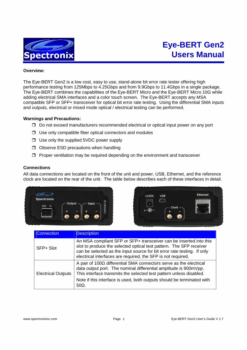
Connections All data connections are located on the front of the unit and power, USB, Ethernet, and the reference clock are located on the rear of the unit. The table below describes each of these interfaces in detail.
Connection Description
SFP+ Slot
An MSA compliant SFP or SFP+ transceiver can be inserted into this slot to produce the selected optical test pattern. The SFP receiver can be selected as the input source for bit error rate testing. If only electrical interfaces are required, the SFP is not required.
Electrical Outputs
A pair of 100Ω differential SMA connectors serve as the electrical data output port. The nominal differential amplitude is 900mVpp. This interface transmits the selected test pattern unless disabled. Note if this interface is used, both outputs should be terminated with 50Ω.
www.spectronixinc.com Page Eye-BERT Gen2 User’s Guide V 1.7 2
Connection Description
Electrical Inputs
A pair of 100Ω differential SMA connectors serve as the electrical data input port. This interface can accept differential signals ranging from 50 to 1200mVpp. Note if this interface is used, both inputs should be terminated with 50Ω.
Power input Connect to the supplied 5VDC adapter.
USB Optional computer interface allowing remote control and monitoring using a terminal program or custom user supplied software.
Ethernet Optional computer interface allowing remote control and monitoring using a terminal program or custom user supplied software.
Clock Output
A pair of 100Ω differential SMA connectors serve as the reference clock output port. The nominal differential amplitude is 750mVpp. This clock is synchronous with the transmitted data and is intended to be used for synchronization purposes only. Rise time and jitter characteristics of this output limit its use as an oscilloscope trigger at high bit rates. The table below shows the different clock rates for the various bit rate settings:
Rate Clock Frequency 125 to 155Mbps Rate/1 200Mbps Rate/1.6 622Mbps Rate/4 1.062 to 1.250Gbps Rate/10 2.125 to 2.667Gbps Rate/16 4.25Gbps Rate/32 9.9 to 11.4Gbps Rate/64
Note if this interface is used, both outputs should be terminated with 50Ω.
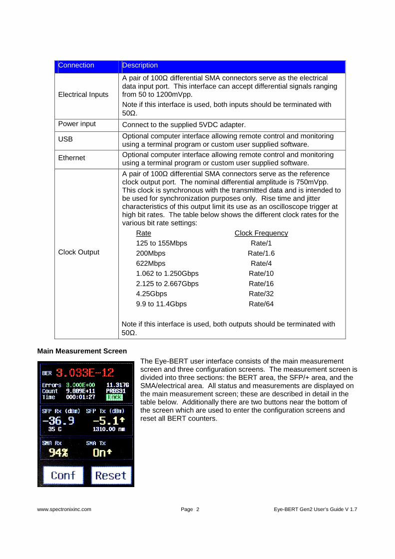
Main Measurement Screen The Eye-BERT user interface consists of the main measurement screen and three configuration screens. The measurement screen is divided into three sections: the BERT area, the SFP/+ area, and the SMA/electrical area. All status and measurements are displayed on the main measurement screen; these are described in detail in the table below. Additionally there are two buttons near the bottom of the screen which are used to enter the configuration screens and reset all BERT counters.

www.spectronixinc.com Page Eye-BERT Gen2 User’s Guide V 1.7 3
BERT Area Description
BER Displays the current bit error rate.
Green: No errors detected since the last reset Red: At least one error has been detected
Errors
The number of bits errors. Green: No errors detected within the last 100mS Red: At least one error has been detected within the last
100mS
Time The total test time since the last reset (hours:minutes:seconds)
Bit Rate Current data rate setting
Pattern Current pattern setting
Lock / LOL Displays the pattern detector/CDR status:
“Lock” Green: CDR and pattern detector are locked “LOL” Red: CDR or pattern detector are not locked
SFP Area Description
Rx Power
Displays the received optical power level as reported by the SFP / SFP+. The color indicates if the receiver has been selected as the BERT measurement interface. This field is displayed only when a transceiver is inserted.
Yellow: Indicates the SFP receiver is the active interface Grey: Indicates the SFP receiver is not the active interface
Tx Power
Displays the transmitted optical power level as reported by the SFP / SFP+. The up/down arrow following the measurement indicates the output polarity. The color indicates if the transmitter has been enabled. This field is displayed only when a transceiver is inserted.
Yellow: Indicates the SFP transmitter is active Grey: Indicates the SFP transmitter is not active
Temperature Displays the SFP/SFP+ temperature
Wavelength Displays the SFP/SFP+ transmitter wavelength
SMA Area Description
SMA Rx
Displays the received electrical level as a percentage of full scale. The color indicates if this input has been selected as the BERT measurement interface.
Yellow: Indicates the SMA input is the active interface Grey: Indicates the SMA input is not the active interface
SMA Tx
Displays the state of the electrical SMA output. The up/down arrow following the measurement indicates the output polarity. The color indicates if the output has been enabled.
Yellow: Indicates the output is active Grey: Indicates the output is not active
Conf Button Pressing this button displays the configuration screens as described in the following section
Reset Button Pressing this button resets all BERT counters
www.spectronixinc.com Page Eye-BERT Gen2 User’s Guide V 1.7 4
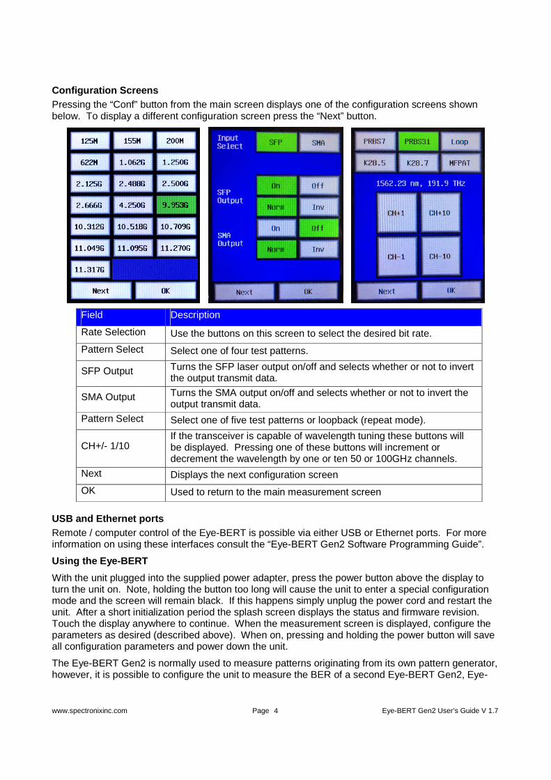
Configuration Screens Pressing the “Conf” button from the main screen displays one of the configuration screens shown below. To display a different configuration screen press the “Next” button.
Field Description
Rate Selection Use the buttons on this screen to select the desired bit rate.
Pattern Select Select one of four test patterns.
SFP Output Turns the SFP laser output on/off and selects whether or not to invert the output transmit data.
SMA Output Turns the SMA output on/off and selects whether or not to invert the output transmit data.
Pattern Select Select one of five test patterns or loopback (repeat mode).
CH+/- 1/10 If the transceiver is capable of wavelength tuning these buttons will be displayed. Pressing one of these buttons will increment or decrement the wavelength by one or ten 50 or 100GHz channels.
Next Displays the next configuration screen
OK Used to return to the main measurement screen
USB and Ethernet ports Remote / computer control of the Eye-BERT is possible via either USB or Ethernet ports. For more information on using these interfaces consult the “Eye-BERT Gen2 Software Programming Guide”.
Using the Eye-BERT
With the unit plugged into the supplied power adapter, press the power button above the display to turn the unit on. Note, holding the button too long will cause the unit to enter a special configuration mode and the screen will remain black. If this happens simply unplug the power cord and restart the unit. After a short initialization period the splash screen displays the status and firmware revision. Touch the display anywhere to continue. When the measurement screen is displayed, configure the parameters as desired (described above). When on, pressing and holding the power button will save all configuration parameters and power down the unit.
The Eye-BERT Gen2 is normally used to measure patterns originating from its own pattern generator, however, it is possible to configure the unit to measure the BER of a second Eye-BERT Gen2, Eye-
www.spectronixinc.com Page Eye-BERT Gen2 User’s Guide V 1.7 5
BERT Micro, or Eye-BERT Micro 10G with some limitations. When testing at rates above 9Gbps simply configure both units with the same rate and pattern and begin testing.
To measure the BER of a signal below 9Gbps originating from a different device, the SFP and SMA Tx outputs must be disabled. This places the device in a special mode that allows it to lock on to a signal originating from a second pattern generator (Eye-BERT Gen2 or Eye-BERT Micro). As with the higher rates, the pattern and rate settings on the two devices must be configured the same. For information on configuring the Eye-BERT Micro and Eye-BERT Micro 10G please see the “Remote BERT Testing” application note.
In version 1.7 tuning capability and loopback (repeat mode) features were added. In loopback mode the Eye-BERT Gen2 will retime and retransmit the signal applied to either the SMA or SFP input. When using loopback mode, the data rate must be set to the same rate as the input signal. If a tunable SFP is used, the last wavelength is stored on power down and restored on power up. If the stored wavelength does not fall within the valid tuning range, the SFP is tuned to the center wavelength.
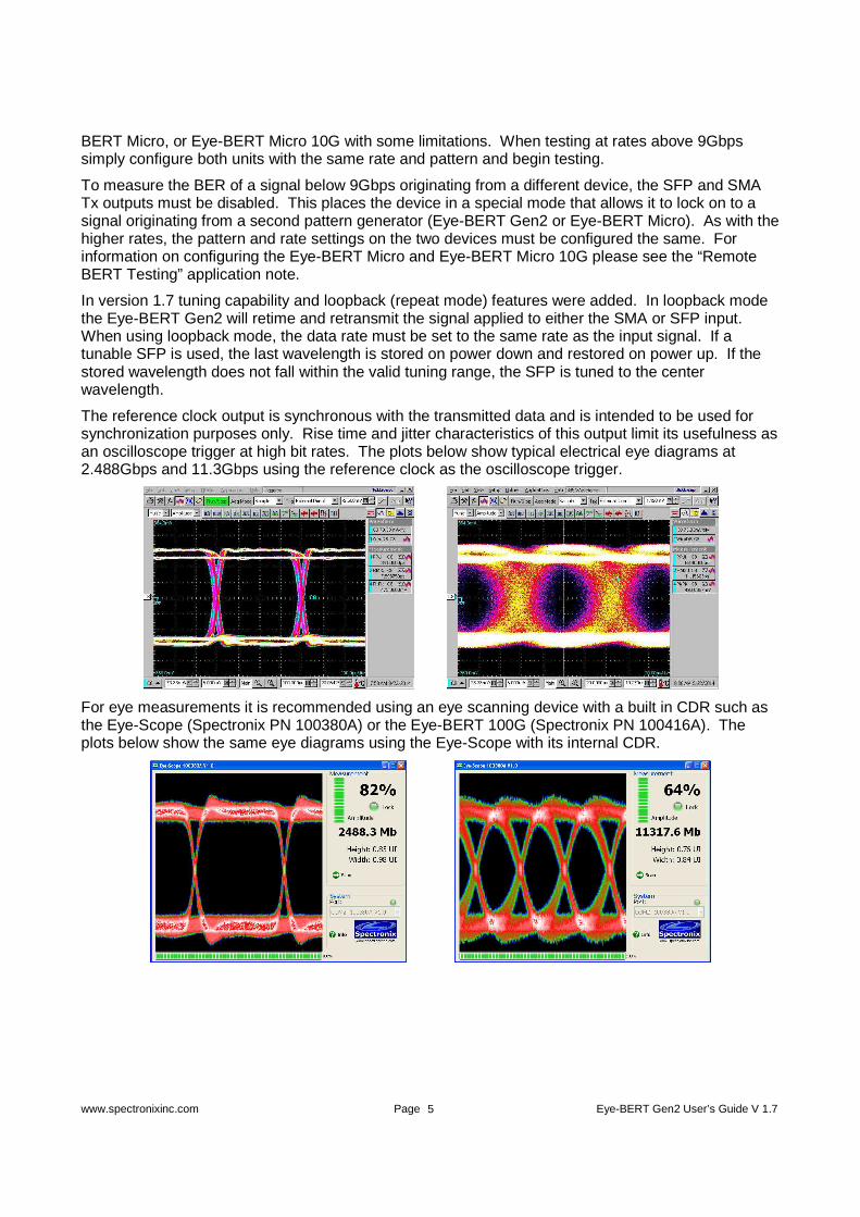
The reference clock output is synchronous with the transmitted data and is intended to be used for synchronization purposes only. Rise time and jitter characteristics of this output limit its usefulness as an oscilloscope trigger at high bit rates. The plots below show typical electrical eye diagrams at 2.488Gbps and 11.3Gbps using the reference clock as the oscilloscope trigger.
For eye measurements it is recommended using an eye scanning device with a built in CDR such as the Eye-Scope (Spectronix PN 100380A) or the Eye-BERT 100G (Spectronix PN 100416A). The plots below show the same eye diagrams using the Eye-Scope with its internal CDR.

www.spectronixinc.com Page Eye-BERT Gen2 User’s Guide V 1.7 6
LETTER OF VOLOTILITY
The Eye-BERT Gen2 contains both volatile and non volatile memory. The Eye-BERT firmware application, settings, and network configuration are stored in non volatile memory and program variables and settings are stored in volatile RAM which is cleared upon power down. The user has no means of directly altering the non volatile memory without opening up the unit and reprogramming the device using a special programming adapter. Therefore there is no clearing procedure.