Eye and Gaze Tracking for Interactive Graphic Displayqji/Papers/smart_graphics.pdf · Eye and Gaze...
7
Eye and Gaze Tracking for Interactive Graphic Display Qiang Ji Dept. of Electrical, Computer, and Systems Eng. Rensselaer Polytechnic Institute [email protected] Zhiwei Zhu Dept. of Computer Science Univ. of Nevada, Reno zhu [email protected] ABSTRACT This paper describes preliminary results we have obtained in developing a computer vision system based on active IR illumination for real time gaze tracking for interactive graphic display. Unlike most of the existing gaze tracking techniques, which often require assuming a static head to work well and require a cumbersome calibration process for each person, our gaze tracker can perform robust and accu- rate gaze estimation without calibration and under rather significant head movement. This is made possible by a new gaze calibration procedure that identifies the mapping from pupil parameters to screen coordinates using the General- ized Regression Neural Networks (GRNN). With GRNN, the mapping does not have to be an analytical function and head movement is explicitly accounted for by the gaze map- ping function. Furthermore, the mapping function can gen- eralize to other individuals not used in the training. The effectiveness of our gaze tracker is demonstrated by prelim- inary experiments that involve gaze-contingent interactive graphic display. Keywords eye tracking, gaze estimation, HCI, Interactive Graphic Dis- play 1. INTRODUCTION Gaze determines the user’s current line of sight or point of fixation. The fixation point is defined as the intersection of the line of sight with the surface of the object (such as the screen) being viewed. Gaze may be used to interpret the user’s intention for non-command interactions and to enable (fixation dependent) accommodation and dynamic depth of focus. The potential benefits for incorporating eye movements into the interaction between humans and com- puters are numerous. For example, knowing the location of a user’s gaze may help a computer to interpret a user’s request and possibly enable a computer to ascertain some cognitive states of the user, such as confusion or fatigue. Permission to make digital or hard copies of all or part of this work for personal or classroom use is granted without fee provided that copies are not made or distributed for profit or commercial advantage and that copies bear this notice and the full citation on the first page. To copy otherwise, to republish, to post on servers or to distribute to lists, requires prior specific permission and/or fee. Int. Symp. on Smart Graphics, June 11-13, 2002, Hawthorne, NY, USA. Copyright 2002 ACM 1-58113-216-6/02/07 ..$5.00 In addition, real time monitoring of gaze position permits the introduction of display changes that are contingent on the spatial or temporal characteristics of eye movements. Such methodology is referred to as gaze contingent display paradigm. For example, gaze may be used to determine one’s fixation on the screen, which can then used to infer what information the user is interested in. Appropriate ac- tions can then be taken such as increasing the resolution or increasing the size of the region where the user fixates. Another example is to economize on bandwidth by putting high-resolution information only where the user is currently looking. Gaze tracking is therefore important for HCI and intelli- gent graphics. Numerous techniques have been developed including some commercial eyes trackers. Video-based gaze estimation approaches can be partitioned into head-based approach, ocular-based approach, and the combined head and eye approach. The head based approach determines eye gaze based on the head orientation. In [9], a set of Gabor fil- ters is applied locally to the image region which includes the face. This results in a feature vector to train a neural net- work to predict the two neck angles, pan and tilt, providing the desired information about head orientation. Gaze esti- mation by head orientation, however, only provides a global gaze since one’s gaze can still vary considerably given the head orientation. Ocular-based approach estimates gaze by establishing the relationship between gaze and the geometric properties of the iris or pupil within the eyes. Specifically, the iris-based gaze estimation approach computes gaze by determining the iris location or shape distortions from its image while pupil- based approach determines gaze based on the relative spatial positions between pupil and the glint (cornea reflection). Neural networks have been used in the past for this task [1, 11]. The idea is to extract a small window containing the eye and feed it, after proper intensity normalization, to a neural network. The output of the network determines the coordinates of the gaze. So far, the most common approach for ocular-based gaze es- timation is based on the relative position between pupil and the glint on the cornea of the eye [2, 4, 5, 8, 7, 3]. Assum- ing a static head, methods based on this idea use the glint as a reference point, thus the vector from the glint to the center of the pupil will describe the gaze direction. While contact-free and non-intrusive, these methods work well only
-
Upload
phamkhuong -
Category
Documents
-
view
219 -
download
0
Transcript of Eye and Gaze Tracking for Interactive Graphic Displayqji/Papers/smart_graphics.pdf · Eye and Gaze...
Eye and Gaze Tracking for Interactive Graphic Display
Qiang JiDept. of Electrical, Computer, and Systems Eng.
Rensselaer Polytechnic Institute
Zhiwei ZhuDept. of Computer Science
Univ. of Nevada, Reno
ABSTRACTThis paper describes preliminary results we have obtainedin developing a computer vision system based on activeIR illumination for real time gaze tracking for interactivegraphic display. Unlike most of the existing gaze trackingtechniques, which often require assuming a static head towork well and require a cumbersome calibration process foreach person, our gaze tracker can perform robust and accu-rate gaze estimation without calibration and under rathersignificant head movement. This is made possible by a newgaze calibration procedure that identifies the mapping frompupil parameters to screen coordinates using the General-ized Regression Neural Networks (GRNN). With GRNN,the mapping does not have to be an analytical function andhead movement is explicitly accounted for by the gaze map-ping function. Furthermore, the mapping function can gen-eralize to other individuals not used in the training. Theeffectiveness of our gaze tracker is demonstrated by prelim-inary experiments that involve gaze-contingent interactivegraphic display.
Keywordseye tracking, gaze estimation, HCI, Interactive Graphic Dis-play
1. INTRODUCTIONGaze determines the user’s current line of sight or point offixation. The fixation point is defined as the intersectionof the line of sight with the surface of the object (such asthe screen) being viewed. Gaze may be used to interpretthe user’s intention for non-command interactions and toenable (fixation dependent) accommodation and dynamicdepth of focus. The potential benefits for incorporating eyemovements into the interaction between humans and com-puters are numerous. For example, knowing the locationof a user’s gaze may help a computer to interpret a user’srequest and possibly enable a computer to ascertain somecognitive states of the user, such as confusion or fatigue.
Permission to make digital or hard copies of all or part of this work forpersonal or classroom use is granted without fee provided that copies arenot made or distributed for profit or commercial advantage and that copiesbear this notice and the full citation on the first page. To copy otherwise, torepublish, to post on servers or to distribute to lists, requires prior specificpermission and/or fee.Int. Symp. on Smart Graphics, June 11-13, 2002, Hawthorne, NY, USA.Copyright 2002 ACM 1-58113-216-6/02/07 ..$5.00
In addition, real time monitoring of gaze position permitsthe introduction of display changes that are contingent onthe spatial or temporal characteristics of eye movements.Such methodology is referred to as gaze contingent displayparadigm. For example, gaze may be used to determineone’s fixation on the screen, which can then used to inferwhat information the user is interested in. Appropriate ac-tions can then be taken such as increasing the resolutionor increasing the size of the region where the user fixates.Another example is to economize on bandwidth by puttinghigh-resolution information only where the user is currentlylooking.
Gaze tracking is therefore important for HCI and intelli-gent graphics. Numerous techniques have been developedincluding some commercial eyes trackers. Video-based gazeestimation approaches can be partitioned into head-basedapproach, ocular-based approach, and the combined headand eye approach. The head based approach determines eyegaze based on the head orientation. In [9], a set of Gabor fil-ters is applied locally to the image region which includes theface. This results in a feature vector to train a neural net-work to predict the two neck angles, pan and tilt, providingthe desired information about head orientation. Gaze esti-mation by head orientation, however, only provides a globalgaze since one’s gaze can still vary considerably given thehead orientation.
Ocular-based approach estimates gaze by establishing therelationship between gaze and the geometric properties ofthe iris or pupil within the eyes. Specifically, the iris-basedgaze estimation approach computes gaze by determining theiris location or shape distortions from its image while pupil-based approach determines gaze based on the relative spatialpositions between pupil and the glint (cornea reflection).Neural networks have been used in the past for this task [1,11]. The idea is to extract a small window containing theeye and feed it, after proper intensity normalization, to aneural network. The output of the network determines thecoordinates of the gaze.
So far, the most common approach for ocular-based gaze es-timation is based on the relative position between pupil andthe glint on the cornea of the eye [2, 4, 5, 8, 7, 3]. Assum-ing a static head, methods based on this idea use the glintas a reference point, thus the vector from the glint to thecenter of the pupil will describe the gaze direction. Whilecontact-free and non-intrusive, these methods work well only

for a static head, which is a rather restrictive constraint onthe part of the user. Even minor head movement can failthese techniques. This poses a significant hurdle to naturalhuman computer interaction (HCI). Another serious prob-lem with the existing eyes and gaze tracking systems is theneed to perform a rather cumbersome calibration processfor each individual. The latest research efforts are aimedat overcoming this limitation. Researchers from NTT inJapan proposed [8] a new gaze tracking technique based onmodelling the eyeball. Their technique significantly simpli-fies the gaze calibration procedure, requiring only 2 pointsto perform the necessary calibration. The method, however,still requires relatively stationary head, and there exists diffi-culty in acquiring accurate geometric eyeball model for eachsubject. Researchers from IBM [7] is also studying the feasi-bility of completely eliminating the need of gaze calibrationprocedure by using two cameras and by exploiting the ge-ometry of eyes and their images. Other recent efforts [12, 3]also focus on improving the eye tracking robustness undervarious lighting conditions.
In this paper, we propose to improve this approach so thatgaze tracking can be accomplished robustly, accurately, nat-urally, and without the need of calibration.
2. EYE TRACKINGGaze tracking starts with eye tracking. For eye tracking,we track pupils instead. We use infrared LEDs that oper-ate at a power of 32mW in a wavelength band 40nm wideat a nominal wavelength of 880nm. As in Ji [6], we obtaina dark and a bright pupil image by illuminating the eyeswith IR LEDs located off (the outer IR ring) and on theoptical axis (the inner IR ring), respectively. To further im-prove the quality of the image and to minimize interferencefrom light sources other than the IR illuminator, we use anoptical band-pass filter which has a wavelength pass bandonly 10nm wide. The filter has increased the signal-to-noiseratio significantly, compared to the case without using thefilter. Figure 1 illustrates the IR illuminator consisting oftwo concentric IR rings and the band-pass filter.
Figure 1: Hardware setup: the camera with an ac-tive IR illuminator.
Pupils detection and tracking start with pupils detection in
the initial frames, followed by tracking. Pupil detection isaccomplished based on both the intensity of the pupils (thebright and dark pupils as shown in Fig. 3 and on the appear-ance of the eyes using the support vector machine. The useof support vector machine (SVM) avoids falsely identifying abright region as a pupil. Specifically, candidates of pupils arefirst detected from the difference image resulted from sub-tracting the dark pupil image from the bright pupil image.The pupil candidates are then validated using SVM to re-move spurious pupil candidates. Given the detected pupils,pupils in the subsequent frames can be detected efficientlyvia tracking. Kalman filtering is used since it allows pupilspositions in the previous frame to predict pupils position incurrent frame, therefore greatly limiting the search space.Kalman filtering tracking based on pupil intensity is there-fore implemented. To avoid Kalman filtering go awry dueto the use of only intensity, Kalman filtering is augmentedby mean-shift tracking, which tracks an object based on itsintensity distribution. Details on eye detection and trackingmay be found in [12].
3. GAZE DETERMINATION AND TRACK-ING
Our gaze estimation algorithm consists of three parts: pupil-glint detection and tracking, gaze calibration, and gaze map-ping. For this research, one’s gaze is quantized into 8 regionson the screen (4 × 2) as shown in Fig.2.
1
8 �
2
6 7 �
3 �
4
5
Figure 2: The quantized eye gaze regions on a computer
screen
3.1 Pupil and Glint Detection and TrackingGaze estimation starts with pupil-glint detection and track-ing. For gaze estimation, we continue using the IR illumi-nator as shown in Figure 1. To produce the desired pupileffects, the two rings are turned on and off alternately viathe video decoder we developed to produce the so calledbright and dark pupil effect as shown in Figure 3 (a) and(b).
Note glint (the small brightest spot) appears on both images.Given a bright pupil image, the pupil detection and trackingtechnique described in section 2 can be directly applied forpupil detection and tracking. The location of a pupil at eachframe is characterized by its centroid. Algorithm-wise, glintcan be detected much more easily from the dark image sinceboth glint and pupil appear equally bright and sometimesoverlap on the bright pupil image. In the dark image on theother hand, the glint is much brighter than the rest of the

(a)
(b)
Figure 3: Bright (a) and dark (b) pupils imageswith glint.
eye image, which makes glint detection and tracking mucheasier. The pupil detection and tracking technique can beused to detect and track glint from the dark images. Figure4 (c) show the detected glint and pupil.
3.2 Gaze CalibrationGiven the detected glint and pupil, a mapping function isoften used to map the pupil-glint vector to gaze (screen co-ordinates). Figure 4 shows the relationship between gazeand the relative position between the glint and the pupil.The mapping function is often determined via a calibration
(a) (b) (c)look left
(a) (b) (c)look frontal
Figure 4: Relative spatial relationship between glint
and bright pupil center used to determine eye-gaze posi-
tion. (a) bright pupil images, (b) glint images; (c) pupil-
glint relationship generated by superimposing glint to
the thresholded bright pupil images.
procedure. The calibration process determines the parame-ters for the mapping function given a set of pupil-glint vec-tors and the corresponding screen coordinates (gazes). Theconventional approach for gaze calibration suffers from two
shortcomings: 1) most of the mapping is assumed an ana-lytical function of either linear or second order polynomial,which may not be reasonable due to perspective projectionand spherical surface of the eye; 2) only coordinate displace-ments between pupil center and glint position are used forgaze estimation. This makes the calibration face orienta-tion dependent. Another calibration is needed if the headhas moved since last calibration, even for minor head move-ment. In practice, it is difficult to keep head still and theexisting gaze tracking methods will produce incorrect re-sult if the head moves, even slightly. Head movement musttherefore be incorporated in the gaze estimation procedure.Another problem is that the mapping function derived forone person is not applicable to another. The calibrationmust, therefore, be performed for each individual. Here, weintroduce a new gaze calibration based on Neural Networkto overcome these two limitations.
3.3 Gaze Calibration Via Generalized Regres-sion Neural Networks (GRNN)
The reason to use NN is because of the difficulty in analyt-ically deriving the mapping function that relates pupil andglint parameters to gaze under different face poses and fordifferent persons. Given sufficient pupil and glint parame-ters, we believe there exists an unique function that relategaze to different pupil and glint parameters.
Introduced in 1991 by D.L.Specht [10] as generalization ofboth radial basis function networks (RBFNs) and probabilis-tic neural networks (PNNs), GRNNs have been successfullyused in function approximation applications. GRNNs arememory-based feed forward networks based on the estima-tion of probability density functions. GRNNs feature fasttraining times, can model non-linear functions, and havebeen shown to perform well in noisy environments givenenough data. Our experiments with different types of NNalso reveal superior perform of GRNN over the conventionalfeed forward back propagation NN.
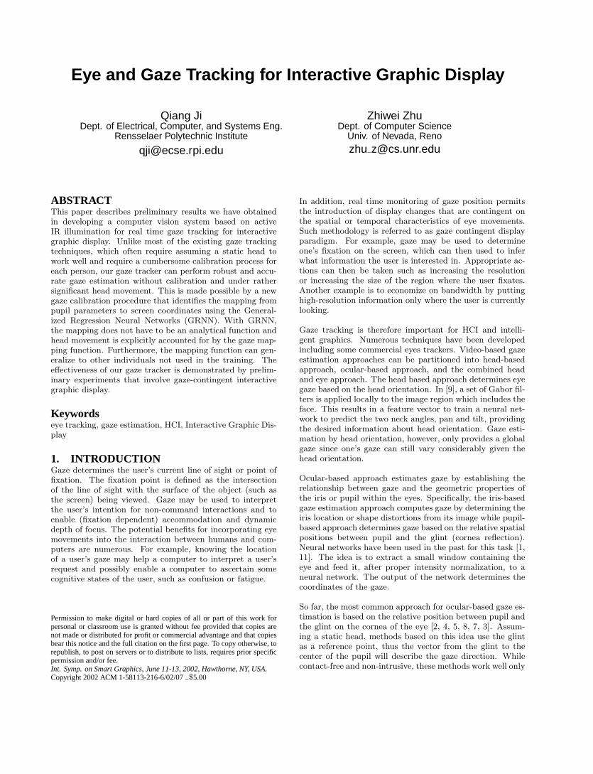
The GRNN topology consists of 4 layers: the input layer,the hidden layer, the summation layer, and the output layer.The input layer has six inputs, representing the six param-eters while the output layer has one node. The number ofhidden nodes is equal to the number of training samples,with one hidden node added for each set of training sample.The number of nodes in the summation layer is equal to thenumber of output nodes plus 1. Figure 5 shows the GRNNarchitecture we use.
Due to significant difference in horizontal and vertical spa-tial gaze resolution, two identical GRNN networks were con-structed, with output node representing the horizontal andvertical gaze coordinates sx and sy respectively.
The parameters to use for the input layer must vary with dif-ferent face distances and orientations to the camera. Specif-ically, the input vector to the GRNN is
g =[
∆x ∆y r θ gx gy
]where ∆x and ∆y are the pupil-glint displacement, r is theratio of the major to minor axes of the ellipse that fits tothe pupil, θ is the ellipse orientation, and gx and gy are theglint image coordinates.
������������� ��� �
�������� ���������� ��� �
� ������� ���� ��� �
����������� ��� �
�����������
Figure 5: GRNN architecture used for gaze calibra-tion
The choice of these input parameters is based on the follow-ing rational. ∆x and ∆y account for the relative movementbetween the glint and the pupil. The magnitude of the glint-pupil vector can also relate to the distance of the subject tothe camera. r is used to account for face orientation. Theratio should be close to one when the face is frontal. The ra-tio becomes larger or less than 1 when the face turns eitherup/down or left/right. Angle θ is used to account for facerotation around the camera optical axis. Finally, (gx, gy)are used to account for the in-plane head translation. Theuse of these parameters allows to account for both head andpupil movement since head movement and pupil movementwill introduce corresponding changes to these parameters.This effectively reduces the head movement influence. Fur-thermore, the input parameters are chosen such that theyremain relatively constant for different people. For example,these parameters are independent of the size of the pupils,which often vary among people. The determined gaze map-ping function, therefore, will be able to generalize. Thiseffectively eliminates the need to re-calibrate for anotherperson.
Before supplying to the GRNN, the input vector is nor-malized appropriately. The normalization ensures all in-put features are in the same range. A large amount oftraining data under different head positions are collectedto train the GRNN. During the training data acquisition,the user is asked to fixate his/her gaze on each gaze re-gion. On each fixation, 10 sets of input parameters are col-lected so that outliers can be identified subsequently. Fur-thermore, to collect representative data, we use one subjectfrom each race including an Asian subject and a Caucasiansubject. In the future, we will extend the training to addi-tional races. The subjects ages range from 25 to 65. The ac-quired training data, after appropriate preprocessing (e.g.,non-linear filtering to remove outliers) and normalization,is then used to train the NN to obtain the weights of theGRNN. GRNNs are trained using an one-pass learning al-gorithm and is therefore very fast.
3.4 Gaze MappingAfter training, given an input vector, the GRNN can thenclassify it into one of the 8 screen regions.
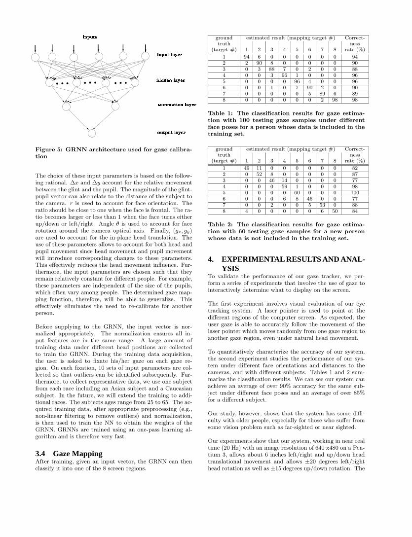
ground estimated result (mapping target #) Correct-truth ness
(target #) 1 2 3 4 5 6 7 8 rate (%)
1 94 6 0 0 0 0 0 0 942 2 90 8 0 0 0 0 0 903 0 3 88 7 0 2 0 0 884 0 0 3 96 1 0 0 0 965 0 0 0 0 96 4 0 0 966 0 0 1 0 7 90 2 0 907 0 0 0 0 0 5 89 6 898 0 0 0 0 0 0 2 98 98
Table 1: The classification results for gaze estima-tion with 100 testing gaze samples under differentface poses for a person whose data is included in thetraining set.
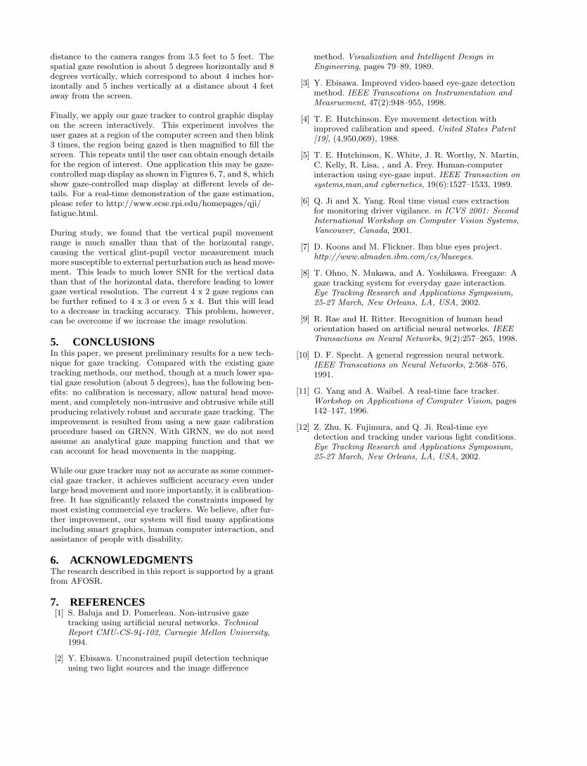
ground estimated result (mapping target #) Correct-truth ness
(target #) 1 2 3 4 5 6 7 8 rate (%)
1 49 11 0 0 0 0 0 0 822 0 52 8 0 0 0 0 0 873 0 0 46 14 0 0 0 0 774 0 0 0 59 1 0 0 0 985 0 0 0 0 60 0 0 0 1006 0 0 0 6 8 46 0 0 777 0 0 2 0 0 5 53 0 888 4 0 0 0 0 0 6 50 84
Table 2: The classification results for gaze estima-tion with 60 testing gaze samples for a new personwhose data is not included in the training set.
4. EXPERIMENTAL RESULTS AND ANAL-YSIS
To validate the performance of our gaze tracker, we per-form a series of experiments that involve the use of gaze tointeractively determine what to display on the screen.
The first experiment involves visual evaluation of our eyetracking system. A laser pointer is used to point at thedifferent regions of the computer screen. As expected, theuser gaze is able to accurately follow the movement of thelaser pointer which moves randomly from one gaze region toanother gaze region, even under natural head movement.
To quantitatively characterize the accuracy of our system,the second experiment studies the performance of our sys-tem under different face orientations and distances to thecameras, and with different subjects. Tables 1 and 2 sum-marize the classification results. We can see our system canachieve an average of over 90% accuracy for the same sub-ject under different face poses and an average of over 85%for a different subject.
Our study, however, shows that the system has some diffi-culty with older people, especially for those who suffer fromsome vision problem such as far-sighted or near sighted.
Our experiments show that our system, working in near realtime (20 Hz) with an image resolution of 640 x480 on a Pen-tium 3, allows about 6 inches left/right and up/down headtranslational movement and allows ±20 degrees left/righthead rotation as well as ±15 degrees up/down rotation. The
distance to the camera ranges from 3.5 feet to 5 feet. Thespatial gaze resolution is about 5 degrees horizontally and 8degrees vertically, which correspond to about 4 inches hor-izontally and 5 inches vertically at a distance about 4 feetaway from the screen.
Finally, we apply our gaze tracker to control graphic displayon the screen interactively. This experiment involves theuser gazes at a region of the computer screen and then blink3 times, the region being gazed is then magnified to fill thescreen. This repeats until the user can obtain enough detailsfor the region of interest. One application this may be gaze-controlled map display as shown in Figures 6, 7, and 8, whichshow gaze-controlled map display at different levels of de-tails. For a real-time demonstration of the gaze estimation,please refer to http://www.ecse.rpi.edu/homepages/qji/fatigue.html.
During study, we found that the vertical pupil movementrange is much smaller than that of the horizontal range,causing the vertical glint-pupil vector measurement muchmore susceptible to external perturbation such as head move-ment. This leads to much lower SNR for the vertical datathan that of the horizontal data, therefore leading to lowergaze vertical resolution. The current 4 x 2 gaze regions canbe further refined to 4 x 3 or even 5 x 4. But this will leadto a decrease in tracking accuracy. This problem, however,can be overcome if we increase the image resolution.
5. CONCLUSIONSIn this paper, we present preliminary results for a new tech-nique for gaze tracking. Compared with the existing gazetracking methods, our method, though at a much lower spa-tial gaze resolution (about 5 degrees), has the following ben-efits: no calibration is necessary, allow natural head move-ment, and completely non-intrusive and obtrusive while stillproducing relatively robust and accurate gaze tracking. Theimprovement is resulted from using a new gaze calibrationprocedure based on GRNN. With GRNN, we do not needassume an analytical gaze mapping function and that wecan account for head movements in the mapping.
While our gaze tracker may not as accurate as some commer-cial gaze tracker, it achieves sufficient accuracy even underlarge head movement and more importantly, it is calibration-free. It has significantly relaxed the constraints imposed bymost existing commercial eye trackers. We believe, after fur-ther improvement, our system will find many applicationsincluding smart graphics, human computer interaction, andassistance of people with disability.
6. ACKNOWLEDGMENTSThe research described in this report is supported by a grantfrom AFOSR.
7. REFERENCES[1] S. Baluja and D. Pomerleau. Non-intrusive gaze
tracking using artificial neural networks. TechnicalReport CMU-CS-94-102, Carnegie Mellon University,1994.
[2] Y. Ebisawa. Unconstrained pupil detection techniqueusing two light sources and the image difference
method. Visualization and Intelligent Design inEngineering, pages 79–89, 1989.
[3] Y. Ebisawa. Improved video-based eye-gaze detectionmethod. IEEE Transcations on Instrumentation andMeasruement, 47(2):948–955, 1998.
[4] T. E. Hutchinson. Eye movement detection withimproved calibration and speed. United States Patent[19], (4,950,069), 1988.
[5] T. E. Hutchinson, K. White, J. R. Worthy, N. Martin,C. Kelly, R. Lisa, , and A. Frey. Human-computerinteraction using eye-gaze input. IEEE Transaction onsystems,man,and cybernetics, 19(6):1527–1533, 1989.
[6] Q. Ji and X. Yang. Real time visual cues extractionfor monitoring driver vigilance. in ICVS 2001: SecondInternational Workshop on Computer Vision Systems,Vancouver, Canada, 2001.
[7] D. Koons and M. Flickner. Ibm blue eyes project.http://www.almaden.ibm.com/cs/blueeyes.
[8] T. Ohno, N. Mukawa, and A. Yoshikawa. Freegaze: Agaze tracking system for everyday gaze interaction.Eye Tracking Research and Applications Symposium,25-27 March, New Orleans, LA, USA, 2002.
[9] R. Rae and H. Ritter. Recognition of human headorientation based on artificial neural networks. IEEETransactions on Neural Networks, 9(2):257–265, 1998.
[10] D. F. Specht. A general regression neural network.IEEE Transcations on Neural Networks, 2:568–576,1991.
[11] G. Yang and A. Waibel. A real-time face tracker.Workshop on Applications of Computer Vision, pages142–147, 1996.
[12] Z. Zhu, K. Fujimura, and Q. Ji. Real-time eyedetection and tracking under various light conditions.Eye Tracking Research and Applications Symposium,25-27 March, New Orleans, LA, USA, 2002.

Figure 6: The map of the United States, with the gaze-selected region as marked by the shaded circle andthe associated rectangle around it.

Figure 7: The blown-up area for the selected region in Fig. 6. Another selection is made by gaze on thisimage as indicated by the shaded circle and the associated rectangle around it.
Figure 8: The blown-up area for the selected region in Fig. 7. Another selection is made by gaze on thisimage as indicated by the shaded circle and the associated rectangle around it.